WO2023095626A1 - 無線通信装置および方法、並びに、無線通信端末および方法 - Google Patents
無線通信装置および方法、並びに、無線通信端末および方法 Download PDFInfo
- Publication number
- WO2023095626A1 WO2023095626A1 PCT/JP2022/041873 JP2022041873W WO2023095626A1 WO 2023095626 A1 WO2023095626 A1 WO 2023095626A1 JP 2022041873 W JP2022041873 W JP 2022041873W WO 2023095626 A1 WO2023095626 A1 WO 2023095626A1
- Authority
- WO
- WIPO (PCT)
- Prior art keywords
- sounding
- wireless communication
- information
- link
- mode
- Prior art date
- Legal status (The legal status is an assumption and is not a legal conclusion. Google has not performed a legal analysis and makes no representation as to the accuracy of the status listed.)
- Ceased
Links
Images




Classifications
-
- H—ELECTRICITY
- H04—ELECTRIC COMMUNICATION TECHNIQUE
- H04W—WIRELESS COMMUNICATION NETWORKS
- H04W16/00—Network planning, e.g. coverage or traffic planning tools; Network deployment, e.g. resource partitioning or cells structures
- H04W16/24—Cell structures
- H04W16/28—Cell structures using beam steering
-
- H—ELECTRICITY
- H04—ELECTRIC COMMUNICATION TECHNIQUE
- H04W—WIRELESS COMMUNICATION NETWORKS
- H04W76/00—Connection management
- H04W76/20—Manipulation of established connections
-
- H—ELECTRICITY
- H04—ELECTRIC COMMUNICATION TECHNIQUE
- H04W—WIRELESS COMMUNICATION NETWORKS
- H04W24/00—Supervisory, monitoring or testing arrangements
- H04W24/10—Scheduling measurement reports ; Arrangements for measurement reports
-
- H—ELECTRICITY
- H04—ELECTRIC COMMUNICATION TECHNIQUE
- H04W—WIRELESS COMMUNICATION NETWORKS
- H04W84/00—Network topologies
- H04W84/02—Hierarchically pre-organised networks, e.g. paging networks, cellular networks, WLAN [Wireless Local Area Network] or WLL [Wireless Local Loop]
- H04W84/10—Small scale networks; Flat hierarchical networks
- H04W84/12—WLAN [Wireless Local Area Networks]
-
- H—ELECTRICITY
- H04—ELECTRIC COMMUNICATION TECHNIQUE
- H04W—WIRELESS COMMUNICATION NETWORKS
- H04W88/00—Devices specially adapted for wireless communication networks, e.g. terminals, base stations or access point devices
- H04W88/02—Terminal devices
- H04W88/06—Terminal devices adapted for operation in multiple networks or having at least two operational modes, e.g. multi-mode terminals
Definitions
- the present technology relates to a wireless communication device and method, and a wireless communication terminal and method, and more particularly to a wireless communication device and method, and a wireless communication terminal and method that enable efficient sounding.
- a “link” is a wireless transmission path that allows data transmission between two wireless communication devices.
- MLD Multi-link Device
- SAP service access point
- AP Access Point, Access Point Multi Link Device, AP-MLD
- AP-MLD Access Point, Access Point Multi Link Device
- STA Station Multi Link Device
- Non-AP Multi Link Device Non-AP MLD
- STA-MLD STA-MLD
- a STA is equipped with, for example, two antennas and operates by assigning one antenna to each of two links, or by assigning two antennas to one link for MIMO.
- the former operation mode will be referred to as the Default MLO mode
- the latter operation mode will be referred to as the Legacy mode.
- MIMO cannot be used for communication and transmission speed is limited.
- legacy mode only one link is available for communication, limiting the links from which the AP can acquire transmission opportunities.
- ELMMR Enhanced multi-Link multi-radio
- the STA MLD that received the frame switches to assign two antennas to the link that received the frame, and performs frame exchange using AP MLD and MIMO.
- AP MLD can perform MIMO transmission while maintaining a link that can acquire transmission rights.
- STA MLD with EMLMR function can be operated by switching between EMLMR mode and Default MLO mode.
- Sounding estimate of radio wave propagation path characteristics
- Patent Literature 1 shows a method for providing control when a communication device transitions to another frequency band and channel in a multi-band wireless network.
- Patent Document 1 does not consider a configuration such as the ELMMR function in which antennas are shared, and does not clarify how to handle links for each antenna or how to sound channels.
- Non-Patent Document 1 describes a Sounding procedure in the ELMMR function.
- Non-Patent Document 1 shows the following three points. (1) AP MLD does not start sounding at a timing that overlaps with sounding that has already started for STA MLD that has the ELMMR function. (2) STA MLD with the EMLMR function notifies by Capability information whether sounding can be performed simultaneously on multiple links. (3) When AP MLD simultaneously receives NDP Announcement (NDP-A) that notifies transmission of NDP (Null Data Packet), which is a known signal, and NDP at the same time on multiple links, STA MLD Request Sounding for the link again.
- NDP-A NDP Announcement
- Non-Patent Document 1 channel Sounding cannot be completed within a single communication interval, and there is a risk that the channel will fluctuate before the next Sounding communication opportunity is obtained. Also, when the STA MLD performs the sounding, it is difficult to determine whether the sounding is in the ELMMR mode or the default MLO mode.
- This technology was created in view of this situation, and enables efficient sounding to be realized.
- a wireless communication device includes a communication control unit that controls transmission of antenna operation information, which is information related to antenna operation in ELMMR mode Sounding, to a wireless communication terminal.
- a radio communication terminal includes a communication control unit that switches the operation of the antenna based on antenna operation information that is information regarding the operation of the antenna in ELMMR mode Sounding transmitted from a radio communication device. .
- transmission of antenna operation information which is information regarding the operation of the antenna in Sounding in ELMMR mode, to the wireless communication terminal is controlled.
- the operation of the antenna is switched based on antenna operation information, which is information regarding the operation of the antenna in ELMMR mode Sounding transmitted from the wireless communication device.
- FIG. 1 is a diagram illustrating a configuration example of a wireless communication system according to an embodiment of the present technology
- FIG. It is a block diagram showing a configuration example of a wireless communication device to which the present technology is applied.
- FIG. 11 is a block diagram showing another configuration example of a wireless communication device compatible with the EMLMR mode;
- FIG. 2 is a diagram showing a sequence of sounding of multiple links assumed in conventional Multi-Link.
- FIG. 2 is a diagram showing a single-link Sounding sequence assumed in conventional Multi-Link;
- FIG. 10 is a diagram showing a Sounding sequence for simultaneous multiple links to which the present technology is applied;
- FIG. 10 is a diagram showing a modified sequence of Sounding for multiple links at the same time to which the present technology is applied;
- FIG. 4 is a diagram showing a first configuration example of an NDP-A frame
- FIG. 10 is a diagram showing a second configuration example of an NDP-A frame
- FIG. 10 is a diagram showing a third configuration example of an NDP-A frame
- FIG. 4 is a diagram showing a configuration example of a Link Switch frame
- FIG. 10 is a flowchart for explaining AP MLD Sounding processing
- FIG. 10 is a flowchart for explaining STA MLD Sounding processing
- FIG. FIG. 10 is a diagram showing a single-link Sounding sequence to which the present technology is applied
- It is a block diagram which shows the structural example of a computer.
- FIG. 1 is a diagram showing a configuration example of a wireless communication system according to an embodiment of the present technology.
- data is transmitted and received by wireless communication (MLO) using one or multiple links.
- MLO wireless communication
- each link is selected, for example, from among multiple independent wireless transmission paths divided by frequency bands.
- frequency bands such as 2.4 GHz band, 5 GHz band, 6 GHz band, and 920 MHz band
- each channel is pre-selected from among multiple channels included in one of the bands. channel is used.
- the wireless communication system in Fig. 1 consists of one AP MLD and two STA MLD1 and STA MLD2. Note that the number of STA MLDs is an example and is not limited to two. STA MLD1 and STA MLD2 are connected to AP MLD.
- AP MLD is a wireless communication device that operates as a base station.
- the AP MLD has a function corresponding to MLO operation, and can switch the MLO operation described above (MLO mode consisting of EMLMR mode, Default MLO mode, and Legacy mode).
- STA MLD1 and STA MLD2 are wireless communication devices that operate as terminals.
- STA MLD1 and STA MLD2 have the capability to support at least one of MLO operation and single link communication operation.
- STA MLD1 and STA MLD2 can also switch the MLO operation consisting of the above-mentioned EMLMR mode, Default MLO mode, and Legacy mode.
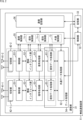
- FIG. 2 is a block diagram showing a configuration example of a wireless communication device to which the present technology is applied.
- the wireless communication device 11 shown in FIG. 2 is a wireless communication device that operates as an AP MLD or STA MLD.
- the wireless communication device 11 is composed of a communication section 31, a control section 32, a storage section 33, antenna groups 41-1 and 41-2, and switching sections 42-1 and 42-2.
- the operation of the antenna groups 41-1 and 41-2 is changed by switching units 42-1 and 42-2, respectively.
- the antenna groups 41-1 and 41-2 are referred to as the antenna group 41 when there is no need to distinguish them, and are referred to as the antennas 41 when there is no need to distinguish the numbers.
- Switching units 42-1 and 42-2 are referred to as switching unit 42 when there is no need to distinguish between them.
- the communication unit 31 transmits and receives data.
- the communication unit 31 is configured to include amplifier units 51-1 and 51-2, radio interface units 52-1 and 52-2, and signal processing units 53-1 and 53-2. Also, the communication unit 31 is configured to include a data processing unit 54 , a communication control unit 55 , and a communication storage unit 56 .
- the amplifiers 51-1 and 51-2, the radio interface units 52-1 and 52-2, and the signal processors 53-1 and 53-2 are respectively the amplifier unit 51 and the radio interface units 53-1 and 53-2. They are called an interface section 52 and a signal processing section 53 .
- the amplifier unit 51 amplifies the analog signal supplied from the wireless interface unit 52 to a predetermined power during transmission, and outputs the analog signal with the amplified power to the antenna group 41 .
- the amplifying unit 51 amplifies the analog signal supplied from the antenna group 41 to a predetermined power during reception, and outputs the amplified analog signal to the wireless interface unit 52 .
- a part of the function of the amplifier section 51 may be included in the wireless interface section 52 . Also, part of the functions of the amplification unit 51 may be a component outside the communication unit 31 .
- the radio interface unit 52 converts the transmission symbol stream from the signal processing unit 53 into an analog signal, performs filtering, up-conversion to a carrier frequency, and phase control, and transmits the phase-controlled analog signal to an amplifier unit. 51.
- the radio interface unit 52 performs phase control, down-conversion, and inverse filtering on the analog signal supplied from the amplifier unit 51, and converts the received symbol stream into a digital signal to the signal processing unit 53. Output.
- the signal processing unit 53 performs encoding, interleaving, modulation, etc. on the data unit supplied from the data processing unit 54, adds a physical header, and outputs the transmission symbol stream to each radio interface unit 52. do.
- the signal processing unit 53 analyzes the physical header of the received symbol stream supplied from each radio interface unit 52 at the time of reception, performs demodulation, deinterleaving, decoding, etc. on the received symbol stream, and generates data units.
- the generated data unit is output to the data processing section 54 .
- the data processing unit 54 is composed of individual data processing units 61-1 and 61-2 and a common data processing unit 62.
- the individual data processing units 61-1 and 61-2 are referred to as individual data processing units 61 when there is no need to distinguish between them.
- the individual data processing unit 61 performs channel access operations based on carrier sense, addition of MAC (Media Access Control) headers and error detection codes to data to be transmitted, and concatenation processing of multiple data units.
- MAC Media Access Control
- the individual data processing unit 61 performs processing for decoupling the MAC header of the received data unit, analysis and error detection, and retransmission request operation.
- the common data processing unit 62 performs sequence management of the data held in the communication storage unit 56 and the control information and management information received from the communication control unit 55 at the time of transmission.
- the common data processing unit 62 also performs encryption processing of control information and management information, etc., generates data units, and allocates the generated data units to the individual data processing units 61-1 and 61-2.
- the common data processing unit 62 performs analysis processing and reorder processing of the data unit when receiving.
- the antenna group 41, the amplifier unit 51, the wireless interface unit 52, the signal processing unit 53, and the individual data processing unit 61 each have the same branch number as surrounded by a broken line (hereinafter also referred to as an individual communication set). ).
- Each set becomes a component of the wireless communication device 11 and performs wireless communication on each link.
- the storage unit 33 may be included in each set.
- An individual communication set is called AP (AP affiliated with AP MLD) or STA (STA affiliated with non-AP MLD).
- the operations of the individual data processing unit 61 and the common data processing unit 62 are not limited to the operations described above, and one of them may perform the operation of the other, for example.
- the individual data processing unit 61 may be set so that all the functions of the common data processing unit 62 are performed for each individual communication set.
- each link used by each group may have a different bandwidth.
- the signal processing unit 53 and the individual data processing unit 61 each have the same branch number, and each of them has one set, and these two sets or three or more sets are connected to one radio interface unit 52. may be
- the communication control section 55 controls the operation of each section of the communication section 31 and information transmission between the sections. Further, the communication control unit 55 performs control to transfer control information and management information to be notified to other wireless communication devices to the individual data processing unit 61 and the common data processing unit 62 .
- the communication control unit 55 has individual control units 71-1 and 71-2 that control each individual communication set, and a common data processing unit 62 and a common control unit 72 that implements control common to each individual communication set.
- the individual control units 71-1 and 71-2 are collectively referred to as the individual control unit 71 when there is no need to distinguish between them.
- the individual control unit 71 when the wireless communication device 11 operates as the AP MLD, the individual control unit 71 provides the wireless communication device operating as the STA MLD with antenna operation information, which is information relating to the operation of the antenna 41 in ELMMR mode Sounding. Control each part to transmit information. At this time, control information for each unit may be transmitted via the common control unit 72 .
- the communication storage unit 56 holds information used by the communication control unit 55.
- the communication storage unit 56 also holds data to be transmitted and data received.
- the control unit 32 is composed of a CPU (Central Processing Unit), ROM (Read Only Memory), RAM (Random Access Memory), and the like.
- the control unit 32 executes programs stored in a ROM or the like, and controls the communication unit 31 and the communication control unit 55 . Also, the control unit 32 may perform part of the operation of the communication control unit 55 instead. Also, the communication control unit 55 and the control unit 32 may be configured as one block.
- the storage unit 33 holds information used by the communication unit 31 and the control unit 32. Moreover, the memory
- the storage unit 33 and the communication storage unit 56 may be configured as one block.
- the antenna group 41, the amplifier unit 51, and the radio interface unit 52 each have the same branch number, and each group has the same branch number.
- the communication unit 31 is realized by one or more LSIs.
- the individual data processing unit 61 is also called Lower MAC.
- the common data processing unit 62 is also called Upper MAC or Higher MAC.
- a set of the individual data processing unit 61 and the common data processing unit 62 is also called an AP entity or a STA entity.
- the communication control unit 55 is also called an MLD (Multi-Link Device) management entity.
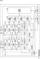
- FIG. 3 is a block diagram showing another configuration example of a wireless communication device compatible with the EMLMR mode.
- the wireless communication device 11 of FIG. 3 dynamically switches which links use the wireless interface unit 52, the amplifier unit 51, and the antenna group 41, which are connected to the individual data processing unit 61 and the signal processing unit 53.
- the only difference is that the wireless communication device 11 of FIG. 2 can be used.
- the individual control unit 71 operates on the link where the antenna group 41 performs sounding based on the antenna operation information transmitted from the wireless communication device operating as the AP MLD.
- the operation of the antenna group 41 is switched so as to
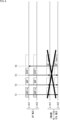
- FIG. 4 is a diagram showing a conventional Sounding sequence for simultaneous multiple links.
- Fig. 4 in multiple links (Link1 and Link2), STA1 (STA1 affiliated with STA MLD) operating on link1 among STAs belonging to STA MLD and STA2 (STA2 affiliated with STA MLD) operating on link2 are sounding at the same time. Examples of implementations are provided. That is, in the figure, link1 indicates the operation on link1 of STA1 belonging to STA MLD, and link2 indicates the operation on link2 of STA2 belonging to STA MLD.
- the solid-line rectangle indicates the frame to be transmitted, and the tip of the arrow extending from the frame indicates the transmission destination of the frame.
- a dashed rectangle indicates that the frame is received at the destination. The same is true for subsequent figures showing other sequences.
- the AP MLD transmits an NDP-A frame to the STA MLD targeted for Sounding, which notifies the implementation of Sounding on multiple links for which transmission opportunities have been acquired.
- Each STA belonging to the STA MLD receives NDP-A frames transmitted simultaneously on each link.
- NDP-A After transmitting NDP-A, AP MLD transmits an NDP frame, which is a signal for Sounding, over multiple links at time T2. Each STA belonging to the STA MLD obtains channel information using NDP frames simultaneously transmitted on each link.
- the AP MLD transmits a BFRP (Beam forming report poll) frame requesting transmission of the acquired channel information to the STA MLD.
- BFRP Beam forming report poll
- STA MLD needs to send a BF report frame, which is a response to the BFRP frame, at time T4.
- a STA MLD that supports the ELMMR mode (hereinafter referred to as an ELMMR mode STA MLD) shares the antenna group 41 with each STA belonging to the STA MLD, so this operation cannot be performed.
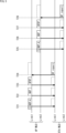
- FIG. 5 is a diagram showing another sequence of Sounding assumed in conventional Multi-Link.
- Fig. 5 shows an example of implementing Sounding with a single link.
- the AP MLD transmits NDP-A to the Sounding target STA MLD on the link (Link1) that acquired the transmission opportunity.
- STA1 belonging to STA MLD receives the NDP-A frame transmitted on Link1.
- AP MLD After transmitting NDP-A, AP MLD transmits an NDP frame, which is a signal for Sounding on Link1, at time T22. STA1 belonging to STA MLD acquires channel information using the NDP frame transmitted on Link1.
- AP MLD transmits a BFRP frame and requests STA MLD to send the acquired channel information.
- STA1 belonging to STA MLD transmits a BF report frame as a response to the BFRP frame.
- the AP MLD and STA MLD similarly acquire transmission opportunities for the other link (Link2) from time T25 to time T28, and perform similar operations.
- the STA MLD cannot determine whether the Sounding that the AP MLD is trying to implement is the Sounding in the EMLMR mode or the Sounding in the Default MLO mode.
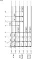
- FIG. 6 is a diagram showing a Sounding sequence to which this technology is applied.
- FIG. 6 shows an example in which sounding is performed simultaneously on multiple links in the wireless communication system of FIG.
- circles shown on links of each STA belonging to STA MLD in ELMMR mode indicate switching of antenna operation.
- a hatched band on each link of each device indicates a section in which a NAV (Network Allocation Vector, transmission prohibited period) is set.
- NAV Network Allocation Vector, transmission prohibited period
- the AP MLD When the AP MLD performs sounding for the STA MLD group including the STA MLD in ELMMR mode, at time t1, it transmits NDP-A with antenna operation information added over multiple links.
- the antenna operation information is information regarding the operation of the antenna 41 in Sounding in ELMMR mode.
- STA MLD in EMLMR mode receives NDP-A sent from AP MLD on multiple links.
- the AP MLD sets NAV on Link1 and Link2 until Sounding is completed.
- the STA MLD in ELMMR mode also completes Sounding on Link1 and Link2 based on the information contained in the NDP-A frame. Set NAV until
- the antenna operation information includes information indicating that the STA MLD group performing Sounding includes an ELMMR mode STA MLD, information indicating that its own Sounding is ELMMR mode Sounding, information indicating the link performing Sounding, and Sounding and information specifying on which link the antenna 41 not used for Sounding should be operated.
- the information indicating that the STA MLD group that performs sounding includes an ELMMR mode STA MLD is, for example, 1-bit flag information that is set when the STA MLD group that performs sounding includes an ELMMR mode STA MLD.
- the information indicating that its own Sounding is ELMMR mode Sounding is information contained in an individual area for each STA MLD in the signal, and a 1-bit flag that is set when its own Sounding is ELMMR mode Sounding information, or information that specifies the type of Sounding that it implements.
- the information indicating the link that performs sounding is the information that specifies the link on which STA MLD in ELMMR mode performs sounding.
- the STA MLD in EMLMR mode switches the operation of the antenna 41 so that the antenna 41 operates on the link on which the sounding is performed, based on the information indicating the link on which the sounding is performed.
- the information indicating the continuation of sounding is the information indicating whether sounding will be performed on other links after sounding on a certain link starting from NDP-A. This is information indicating the number of times to perform Sounding.
- the STA MLD can determine whether or not it is necessary to continue Sounding. can.
- the information specifying on which link the antennas 41 not used for sounding are to be operated is information specifying the link to be operated, information specifically specifying the antenna port to be operated, or information on the number of antennas 41 to be operated. be.
- STA MLD in EMLMR mode operates the antenna 41 that is not used for sounding on another link, so that the link on which the antenna 41 is operated does not generate a blank section of NAV, which is a section in which the NAV is not set.
- AP MLD can eliminate NAV blank intervals by notifying STA MLD of information on NAV blank intervals.
- the information that specifies on which link the operation of the antenna 41 that is not used for Sounding is to be performed is the information that specifies the link at which the STA MLD in ELMMR mode at least grasps the NAV situation.
- the STA MLD in ELMMR mode switches the operation of the antenna 41 so that the antenna 41 operates on Link1 based on the information described in the NDP-A frame transmitted from the AP MLD.
- AP MLD After transmitting the NDP-A frame, AP MLD transmits NDP frames on multiple links at time t3. STA1 belonging to STA MLD receives the NDP frame transmitted from AP MLD on Link1 and acquires channel information using the NDP frame.
- AP MLD sends BFRP frames on multiple links and requests STA MLD to send the acquired channel information.
- STA1 belonging to STA MLD in EMLMR mode receives the transmitted BFRP frame on Link1.
- the ELMMR mode STA MLD transmits a BF report frame on Link1, which is a response to the BFRP frame transmitted at time t4.
- the STA MLD in other modes receives the NDP-A sent at time t1 on multiple links. At this time, STA MLD in other modes also sets NAV on Link1 and Link2 based on the information described in the NDP-A frame until Sounding is completed.
- a STA MLD in other modes receives the NDP frame transmitted at time t3 on multiple links and acquires channel information using the NDP frame.
- a STA MLD in other modes receives the BFRP frame sent from the AP MLD at time t4 on multiple Links. After that, at time t5, each STA belonging to the other mode STA MLD transmits a BF report frame on each Link.
- the AP MLD transmits a Link Switch frame, which includes antenna operation information and is a signal requesting switching of the sounding link, to the STA MLD in ELMMR mode on Link1.
- a Link Switch frame is sent on an active link only to those STA MLDs in ELMMR mode that have a link for which Sounding has not been completed. Not sent to STA MLDs in non-EMLMR mode and STA MLDs for which Sounding has already been completed on all links.
- the Link Switch frame contains antenna operation information that indicates that the STA MLD group performing Sounding includes ELMMR mode STA MLD, and that the own Sounding is ELMMR mode Sounding. , information indicating the link on which Sounding is performed, information indicating continuation of Sounding, and information specifying which link the antenna 41 not used for Sounding should operate.
- the Link Switch frame further includes, as antenna operation information, information regarding the NAV of a link and information requesting transmission of NAV information on a link.
- Information about the NAV of a link is, for example, information about the length of the difference between the NAV length of the STA MLD under the link and the current Time stamp.
- the STA MLD in ELMMR mode can interpolate the blank period of the NAV information generated by Sounding by receiving information about the NAVs of neighboring STA MLDs from the AP MLD.
- Information requesting transmission of NAV information on a certain link is, for example, requesting transmission of the NAV length on a certain link of the subordinate STA MLD to generate information on the NAV of a certain link as described above. Information.
- the STA MLD in ELMMR mode performs ELMMR mode Sounding based on the antenna operation information in the Link Switch frame from time t7 to t10.
- the STA MLD in ELMMR mode can determine on which link the antenna 41 should be operated, and sounding operation can be realized in a single communication section, making it efficient. Sounding can be realized.
- the STA MLD in ELMMR mode operates the antenna 41 so that the antenna 41 operates on Link2 based on the antenna operation information described in the Link Switch frame transmitted from the AP MLD. switch.
- the STA MLD in ELMMR mode may reconfigure the NAV on Link1 and Link2 based on the information described in the Link Switch frame.
- AP MLD After sending the Link Switch frame, AP MLD sends an NDP frame on Link2 at time t8.
- STA2 belonging to STA MLD receives the NDP frame transmitted from AP MLD on Link2 and acquires channel information using the NDP frame.
- AP MLD sends a BFRP frame on Link2 and requests STA MLD to send the acquired channel information.
- STA2 belonging to STA MLD in EMLMR mode receives the transmitted BFRP frame on Link2.
- the STA MLD in ELMMR mode transmits a BF report frame, which is a response to the BFRP frame transmitted at time t9, on Link2.
- the STA MLD can switch the antenna operation based on the antenna operation information, unlike the conventional technique described above with reference to FIG. .
- ELMMR mode Sounding can be performed, so efficient sounding can be achieved even for STA MLD in ELMMR mode.
- FIG. 7 is a diagram showing a modified example sequence of Sounding to which the present technology is applied.
- Link Switch frames were not sent to STA MLDs other than EMLMR mode and STA MLDs for which Sounding has already been completed on all links.
- the Link Switch frame is also sent to STA MLDs in non-EMLMR mode and STA MLDs in ELMMR mode for which Sounding has already been completed on all links.
- AP MLD transmits Link Switch frames to all STA MLDs via Link1.
- the antenna operation information of the Link Switch frame includes information notifying the completion of Sounding.
- Information that notifies the completion of this Sounding may be information sent to all terminals such as a CF (Contention Free)-END frame, or an individual STA sent to a specific STA MLD. It may be information addressed to STA MLD.
- CF Contention Free
- AP MLD when information about NAV is exchanged on a link where Sounding is completed, AP MLD requests a specific STA MLD to send information notifying completion of Sounding and NAV information on a certain link. Send a Link Switch frame containing the information. At t27 after transmitting the Link Switch frame containing the information notifying the completion of Sounding, AP MLD cancels the NAV of Link1 thereafter.
- the STA MLD in ELMMR mode performs ELMMR mode Sounding on Link2 from time t27 to t30 based on the antenna operation information in the Link Switch frame, as in FIG.
- the specific STA MLD releases the NAV of Link1 based on the Link Switch frame, and at time t29, the Link Switch frame is Send a DATA frame containing the requested NAV information on the transmitted Link1.
- the DATA frame cannot be transmitted, but even in ELMMR mode STA MLD, the NAV of Link1 may be canceled based on the Link Switch frame.
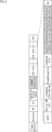
- FIG. 8 is a diagram showing a first configuration example of an NDP-A frame.
- FIG. 8 shows a configuration example of an NDP-A frame when information indicating that the STA MLD group for Sounding includes an ELMMR mode STA MLD is stored in part of the frame body of the NDP-A. ing.
- the NDP-A frame in Fig. 8 consists of fields Frame Control, Duration, RA, TA, Sounding Dialog Token, ELMMR Sounding, STA Info 1 to STA Info n, and FCS.
- Frame Control contains information indicating that this frame is an NDP-A frame.
- Duration contains information about the length of this frame.
- RA contains recipient address information.
- TA includes destination address information.
- Sounding Dialog Token contains NDP information and a series of processing identification numbers.
- EMLMR Sounding is information indicating that the STA MLD group that performs Sounding includes an ELMMR mode STA MLD, and in the case of Fig. 8, it is placed at this position (that is, part of the Frame body).
- STA Info contains information (STA identifier, measurement bandwidth, amount of feedback information, etc.) for each STA MLD that receives an NDP frame and has it measured.
- the STA Info field consists of AID (Association ID) 11, Partial BW info, Feedback Type And Ng, Disambiguation, Codebook Size, Sounding mode, Sounding Link, Sounding Cascade, Antena Allocation, and Nc subfields.
- AID11 contains the STA MLD identifier (AID).
- Partial BW info contains information indicating the measurement band.
- Feedback Type And Ng contains feedback information.
- Disambiguation contains information that prevents STA MLD from erroneously determining AID.
- Codebook Size contains information indicating the size of the codebook.
- Soundingmode contains information indicating whether the own Sounding is ELMMR mode Sounding.
- Sounding Link contains information indicating the link that performs Sounding.
- the Sounding Cascade contains information indicating the continuation of the Sounding operation.
- Antena Allocation contains information specifying on which link the antennas 41 not used for Sounding should be operated.
- Sounding mode Sounding Link
- Sounding Cascade Sounding Cascade
- Antena Allocation may be included in this NDP-A frame in the form of elements.
- NC(number of columns) contains information about the number of columns.
- the FCS field contains an error correction code.
- information indicating that the NDP-A frame stores antenna operation information may be indicated within this NDP-A frame.
- Information indicating an NDP-A frame containing antenna operation information is specified by Frame control or Sounding Dialog token, for example.
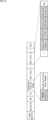
- FIG. 9 is a diagram showing a second configuration example of the NDP-A frame.
- Fig. 9 shows a configuration example of an NDP-A frame when information indicating that the STA MLD group performing Sounding includes an ELMMR mode STA MLD is stored in part of the Sounding Dialog Token.
- An NDP-A frame consists of fields Frame Control, Duration, RA, TA, Sounding Dialog Token, STA Info 1 to STA Info n, and FCS. Note that the description of the parts common to those in FIG. 8 will be omitted.
- the ELMMR Sounding that was placed in part of the Frame body is removed, and the ELMMR Sounding is included in part of the Sounding Dialog Token, which is the same as the NDP-A frame in FIG. -Different from A-frames.
- Sounding Dialog Token is composed of ELMMR Sounding, which is information indicating that STA MLDs in ELMMR mode are included in the STA MLD group that performs Sounding, and Sounding Dialog Token Number subfields.
- FIG. 10 is a diagram showing a third configuration example of the NDP-A frame.
- Fig. 10 shows a configuration example of an NDP-A frame when information indicating that the STA MLD group for Sounding includes an ELMMR mode STA MLD is stored in part of the Frame Control.
- An NDP-A frame consists of fields Frame Control, Duration, RA, TA, Sounding Dialog Token, STA Info 1 to STA Info n, and FCS. Note that the description of the parts common to those in FIG. 8 will be omitted.
- the NDP-A frame in FIG. 10 has the ELMMR Sounding that was placed in part of the Frame body removed and the ELMMR Sounding included in part of the Frame Control, which is different from the NDP-A frame in FIG. It's different than an A-frame.
- the Frame Control is configured to include the Protocol version, Type, and Sub Type subfields.
- Type and Sub Type include information indicating that the STA MLD group for Sounding includes an ELMMR mode STA MLD as additional information indicating that it is an NDP-A frame.
- Type and Sub Type are information that defines what kind of frame the frame is by combining values.
- information indicating that it is NDP-A instead of the information indicating that it is NDP-A, information indicating that the STA MLD group performing Sounding includes an ELMMR mode STA MLD may be stored.
- ELMMR mode STA MLD information indicating that the STA MLD group performing Sounding includes ELMMR mode STA MLDs.
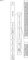
- FIG. 11 is a diagram showing a configuration example of a Link Switch frame.
- the Link Switch frame consists of Frame Control, Duration, Address1 to Address3, Sequence Control, HT (High Throughput) Control, Frame Body, and FCS fields.
- Frame Control contains information indicating that this frame is a Link Switch frame.
- Duration contains information about the length of this frame.
- Address1 to Address3 include, for example, the address of the destination device.
- Sequence Control contains information for controlling the sequence.
- HT Control includes, for example, information necessary for decoding when network coding is applied.
- the Frame Body contains the data part of the Link Switch frame.
- the Frame Body includes subfields such as ELMMR Sounding, Link Release, ..., Link switch for STA m, Link switch for STA n, ..., etc.
- EMLMR Sounding contains information indicating that it is sounding related to ELMMR mode.
- the information contained in EMLMR Sounding is common to any STA MLD.
- Link Release contains information that notifies the completion of Sounding.
- This Link Release is, for example, a sub field that is placed when the Link Release is information transmitted with all terminals as destinations. In other words, when Link Release is information sent to all terminals, it is included in this subfield, which is a common area for all STA MLDs.
- Link switch for STA m and Link switch for STA n are subfields in which individual information is arranged for each STA MLD.
- Link switch for STA m includes Link Release and NAV info request.
- Link Release contains information that notifies the completion of Sounding. This Link Release is placed when sent to a specific STA MLD, STA m. That is, when a Link Release is sent to a specific STA MLD, it is placed in Link switch for STA m, which is an area addressed to an individual STA MLD.
- NAV info request contains information requesting to send NAV information on a certain link.
- Link switch for STA n includes Sounding mode, Sounding Link, Sounding Cascade, and Antena Allocation, similar to STA Info in FIG.
- Link switch for STA n includes NAV reminder, NAV info request, and so on.
- the NAV reminder contains information about the length of the difference between the NAV length of the subordinate STA MLD on a certain link and the current Time stamp.
- NAV info request contains information requesting the transmission of NAV information on a certain link, as described above.
- Information indicating that it is a Link Switch frame may be indicated within this Link Switch frame.
- Information indicating a Link Switch frame is specified by Frame control, for example.
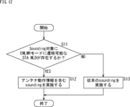
- FIG. 12 is a flowchart for explaining the AP MLD Sounding process.
- step S11 the communication control unit 55 of the AP MLD determines whether or not there is a STA MLD capable of transitioning to the EMLMR mode for Sounding.
- the capability information notified from the STA MLD when the Association is established is used for the determination in step S11.
- step S11 If it is determined in step S11 that there is a STA MLD capable of transitioning to ELMMR mode in the Sounding target, the process proceeds to step S12.
- each individual control unit 71 of the communication control unit 55 performs sounding (FIG. 6 or FIG. 7) including antenna operation information.
- step S11 If it is determined in step S11 that there is no STA MLD capable of transitioning to ELMMR mode for Sounding, the process proceeds to step S13.
- step S13 each individual control unit 71 of the communication control unit 55 performs conventional sounding.
- step S12 or S13 the process ends.
- FIG. 13 is a flowchart for explaining STA MLD Sounding processing.
- the communication control unit 55 of the STA MLD receives NDP-A including antenna operation information.
- each individual control unit 71 of the communication control unit 55 switches the operation of the antenna 41 based on the antenna operation information so that the antenna 41 operates on the sounding link.
- each individual control unit 71 of the communication control unit 55 performs ELMMR mode sounding based on the antenna operation information.
- step S53 the Sounding process ends.
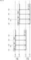
- FIG. 14 is a diagram showing a Sounding sequence to which this technology is applied.
- FIG. 14 shows an example of implementing Sounding with a single link in the wireless communication system of FIG.
- the AP MLD When the AP MLD performs sounding for the STA MLD group including the STA MLD in EMLMR mode, at time t41, it transmits NDP-A with added antenna operation information on Link1. At this time, AP MLD sets NAV on Link1 until Sounding is completed. STA1 belonging to STA MLD in EMLMR mode receives NDP-A transmitted from AP MLD on Link1.
- the STA MLD in ELMMR mode switches the operation of the antenna 41 so that the antenna 41 operates on Link1 based on the information described in the NDP-A frame transmitted from the AP MLD.
- STA MLD in ELMMR mode sets NAV until Sounding is completed on Link1 based on the information described in the NDP-A frame.
- AP MLD After transmitting the NDP-A frame, AP MLD transmits the NDP frame on Link1 at time t43.
- STA1 belonging to STA MLD receives the NDP frame transmitted from AP MLD on Link1 and acquires channel information using the NDP frame.
- AP MLD sends a BFRP frame on Link1 and requests STA MLD to send the acquired channel information.
- STA1 belonging to STA MLD in EMLMR mode receives the transmitted BFRP frame on Link1.
- the ELMMR mode STA MLD transmits a BF report frame on Link1 in response to the BFRP frame transmitted at time t44.
- AP MLD transmits an NDP-A frame with antenna operation information added on Link2.
- AP MLD sets NAV on Link2 until Sounding is completed.
- STA2 belonging to STA MLD in EMLMR mode receives the NDP-A frame transmitted from AP MLD on Link2.
- the STA MLD in ELMMR mode switches the operation of the antenna 41 so that the antenna 41 operates on Link2 based on the information described in the NDP-A frame transmitted from the AP MLD.
- the STA MLD in ELMMR mode sets NAV on Link2 based on the information described in the NDP-A frame until Sounding is completed.
- AP MLD After transmitting the NDP-A frame, AP MLD transmits the NDP frame on Link2 at time t48.
- STA2 belonging to STA MLD receives the NDP frame transmitted from AP MLD on Link2 and acquires channel information using the NDP frame.
- AP MLD sends a BFRP frame on Link2 and requests STA MLD to send the acquired channel information.
- STA2 belonging to STA MLD in EMLMR mode receives the transmitted BFRP frame on Link2.
- the ELMMR mode STA MLD transmits a BF report frame on Link2 in response to the BFRP frame transmitted at time t49.
- ELMMR mode Sounding can be performed, so efficient Sounding can be achieved.
- ELMMR mode Sounding can be performed. This makes it possible to achieve efficient sounding.
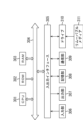
- FIG. 15 is a block diagram showing an example of the hardware configuration of a computer that executes the series of processes described above by a program.
- a CPU (Central Processing Unit) 301 , a ROM (Read Only Memory) 302 and a RAM (Random Access Memory) 303 are interconnected by a bus 304 .
- An input/output interface 305 is further connected to the bus 304 .
- the input/output interface 305 is connected to an input unit 306 such as a keyboard and a mouse, and an output unit 307 such as a display and a speaker.
- the input/output interface 305 is also connected to a storage unit 308 such as a hard disk or nonvolatile memory, a communication unit 309 such as a network interface, and a drive 310 that drives a removable medium 311 .
- the CPU 301 loads a program stored in the storage unit 308 into the RAM 303 via the input/output interface 305 and the bus 304 and executes the above-described series of processes. is done.
- the program executed by the CPU 301 is recorded on the removable media 311, or provided via a wired or wireless transmission medium such as a local area network, the Internet, or digital broadcasting, and installed in the storage unit 308.
- the program executed by the computer may be a program that is processed in chronological order according to the order described in this specification, or may be executed in parallel or at a necessary timing such as when a call is made. It may be a program in which processing is performed.
- a system means a set of multiple components (devices, modules (parts), etc.), and it does not matter whether all the components are in the same housing. Therefore, a plurality of devices housed in separate housings and connected via a network, and a single device housing a plurality of modules in one housing, are both systems. .
- Embodiments of the present technology are not limited to the above-described embodiments, and various modifications are possible without departing from the gist of the present technology.
- this technology can take the configuration of cloud computing in which one function is shared by multiple devices via a network and processed jointly.
- each step described in the flowchart above can be executed by a single device, or can be shared by a plurality of devices.
- one step includes multiple processes
- the multiple processes included in the one step can be executed by one device or shared by multiple devices.
- a radio communication apparatus comprising a communication control unit that controls transmission of antenna operation information, which is information regarding antenna operation in Sounding in ELMMR (Enhanced multi-Link multi-radio) mode, to a radio communication terminal.
- the antenna operation information includes at least one of information indicating that the Sounding is in the ELMMR mode, information indicating the link on which the Sounding is performed, and information specifying on which link the antenna not used for the Sounding should be operated.
- the wireless communication device according to (1) above, including information.
- the wireless communication device according to (1) or (2), wherein the antenna operation information includes information indicating that the wireless communication terminal includes the wireless communication terminal in the ELMMR mode.
- the wireless communication device according to any one of (1) to (3), wherein the antenna operation information includes information indicating continuation of the Sounding.
- the communication control unit performs control so that the antenna operation information is included in a notification signal that notifies transmission of the signal required for the Sounding and is transmitted.
- Device (6) The communication control unit performs control so that the antenna operation information is included in a request signal requesting switching of the link and transmitted to the wireless communication terminal in the EMLMR mode.
- the radio communication apparatus wherein the antenna operation information includes information indicating a length of difference between the length of the NAV of the radio communication terminal under control in a certain link and the time of the current Time stamp.
- the wireless communication device according to (6) or (7), wherein the antenna operation information includes information requesting transmission of NAV information on a certain link.
- the wireless communication device according to any one of (6) to (8), wherein the antenna operation information includes information indicating completion of the Sounding.
- a wireless communication device A wireless communication method for controlling transmission of antenna operation information, which is information relating to antenna operation in ELMMR (Enhanced multi-Link multi-radio) mode Sounding, to a wireless communication terminal.
- ELMMR Enhanced multi-Link multi-radio
- a wireless communication terminal comprising a communication control unit that switches the operation of an antenna based on antenna operation information, which is information on the operation of the antenna in Sounding in an ELMMR (Enhanced multi-link multi-radio) mode transmitted from a wireless communication device.
- the antenna operation information includes at least one of information indicating that the Sounding is in the ELMMR mode, information indicating the link on which the Sounding is performed, and information specifying on which link the antenna not used for the Sounding should be operated.
- the wireless communication terminal according to (11) above including information.
- the antenna operation information is included in a notification signal that notifies transmission of the signal necessary for the Sounding.
- the antenna operation information is included in a request signal requesting switching of the link to the wireless communication terminal in the ELMMR mode.
- the antenna operation information includes information indicating the length of the difference between the length of the NAV of the wireless communication terminal under control in a certain link and the time of the current Time stamp.
- the antenna operation information includes information indicating completion of the Sounding.
- the wireless communication terminal A wireless communication method for switching antenna operation based on antenna operation information, which is information relating to antenna operation in ELMMR mode (Enhanced multi-link multi-radio) sounding transmitted from a wireless communication device.
- 11 wireless communication device 31 communication unit, 41, 41-1, 41-2 antenna, 54 data processing unit, 51, 51-1, 51-2 amplification unit, 52, 52-1, 52-2 wireless interface unit, 53, 53-1, 53-2 signal processing unit, 55 communication control unit, 54 communication storage unit, 61, 61-1, 61-2 individual data processing unit, 62 common data processing unit, 71, 71-1, 71 -2 Separate control unit, 72 Common control unit
Landscapes
- Engineering & Computer Science (AREA)
- Computer Networks & Wireless Communication (AREA)
- Signal Processing (AREA)
- Mobile Radio Communication Systems (AREA)
Abstract
Description
(1)AP MLDは、EMLMR機能を有するSTA MLDに対して、既に開始しているSoundingと時間的に重複するタイミングでSoundingを開始しない。
(2)EMLMR機能を有するSTA MLDは複数リンクで同時にSoundingできるかをCapability情報により通知する。
(3)AP MLDが複数リンクで同時に、既知信号であるNDP(Null Data Packet)の送信を通知するNDP Announcement(以下、NDP-A)と、NDPとを同時に受信した場合、STA MLDは片方のリンクのSoundingのリクエストを再度行う。
1.システム構成および装置構成
2.従来技術
3.第1の実施の形態
4.第2の実施の形態
5.その他
<無線通信システムの構成例>
図1は、本技術の実施の形態に係る無線通信システムの構成例を示す図である。
図2は、本技術を適用する無線通信装置の構成例を示すブロック図である。
<従来の複数リンク同時のSounding>
図4は、従来の複数リンク同時のSoundingのシーケンスを示す図である。
図5は、従来のMulti-Linkで想定されるSoundingの他のシーケンスを示す図である。
<本技術の複数リンク同時のSounding>
図6は、本技術を適用したSoundingのシーケンスを示す図である。
図7は、本技術を適用したSoundingの変形例のシーケンスを示す図である。
図8は、NDP-Aフレームの第1の構成例を示す図である。
図9は、NDP-Aフレームの第2の構成例を示す図である。
図10は、NDP-Aフレームの第3の構成例を示す図である。
図11は、Link Switchフレームの構成例を示す図である。
図12は、AP MLDのSounding処理を説明するフローチャートである。
図13は、STA MLDのSounding処理を説明するフローチャートである。
<本技術の単一リンクのSounding>
図14は、本技術を適用したSoundingのシーケンスを示す図である。
<本技術の効果>
以上のように、本技術においては、無線通信端末に対して、EMLMRモードのSoundingにおけるアンテナの動作に関する情報であるアンテナ動作情報の送信が制御される。
上述した一連の処理は、ハードウェアにより実行することもできるし、ソフトウェアにより実行することもできる。一連の処理をソフトウェアにより実行する場合には、そのソフトウェアを構成するプログラムが、専用のハードウェアに組み込まれているコンピュータ、または汎用のパーソナルコンピュータなどに、プログラム記録媒体からインストールされる。
本技術は、以下のような構成をとることもできる。
(1)
無線通信端末に対して、EMLMR(Enhanced multi-Link multi-radio)モードのSoundingにおけるアンテナの動作に関する情報であるアンテナ動作情報の送信を制御する通信制御部を備える
無線通信装置。
(2)
前記アンテナ動作情報は、前記EMLMRモードの前記Soundingであることを示す情報、前記Soundingを行うリンクを示す情報、および前記Soundingに使用しないアンテナをどのリンクで動作させるかを指定する情報の少なくとも1つの情報を含む
前記(1)に記載の無線通信装置。
(3)
前記アンテナ動作情報は、前記無線通信端末の中に前記EMLMRモードの前記無線通信端末が含まれていることを示す情報を含む
前記(1)または(2)に記載の無線通信装置。
(4)
前記アンテナ動作情報は、前記Soundingの継続を示す情報を含む
前記(1)乃至(3)のいずれかに記載の無線通信装置。
(5)
前記通信制御部は、前記アンテナ動作情報を、前記Soundingに必要な信号の送信を通知する通知信号に含めて送信するように制御する
前記(1)乃至(4)のいずれかに記載の無線通信装置。
(6)
前記通信制御部は、前記アンテナ動作情報を、前記EMLMRモードの前記無線通信端末に対して前記リンクの切り替えを要求する要求信号に含めて送信するように制御する
前記(1)乃至(4)のいずれかに記載の無線通信装置。
(7)
前記アンテナ動作情報は、あるリンクでの配下の前記無線通信端末のNAVの長さから現在のTime stampの時間との差分の長さを示す情報を含む
前記(6)に記載の無線通信装置。
(8)
前記アンテナ動作情報は、あるリンクでのNAV情報を送付することを要請する情報を含む
前記(6)または(7)に記載の無線通信装置。
(9)
前記アンテナ動作情報は、前記Soundingの完了を示す情報を含む
前記(6)乃至(8)のいずれかに記載の無線通信装置。
(10)
無線通信装置が、
無線通信端末に対して、EMLMR(Enhanced multi-Link multi-radio)モードのSoundingにおけるアンテナの動作に関する情報であるアンテナ動作情報の送信を制御する
無線通信方法。
(11)
無線通信装置から送信されてくるEMLMR(Enhanced multi-Link multi-radio)モードのSoundingにおけるアンテナの動作に関する情報であるアンテナ動作情報に基づいて、アンテナの動作を切り替える通信制御部を備える
無線通信端末。
(12)
前記アンテナ動作情報は、前記EMLMRモードの前記Soundingであることを示す情報、前記Soundingを行うリンクを示す情報、および前記Soundingに使用しないアンテナをどのリンクで動作させるかを指定する情報の少なくとも1つの情報を含む
前記(11)に記載の無線通信端末。
(13)
前記アンテナ動作情報は、無線通信端末の中に前記EMLMRモードの前記無線通信端末が含まれていることを示す情報を含む
前記(11)または(12)に記載の無線通信端末。
(14)
前記アンテナ動作情報は、前記Soundingの継続を示す情報を含む
前記(11)乃至(13)のいずれかに記載の無線通信端末。
(15)
前記アンテナ動作情報は、前記Soundingに必要な信号の送信を通知する通知信号に含めて送信されてくる
前記(11)乃至(14)のいずれかに記載の無線通信端末。
(16)
前記アンテナ動作情報は、前記EMLMRモードの無線通信端末に対して前記リンクの切り替えを要求する要求信号に含めて送信されてくる
前記(11)乃至(14)のいずれかに記載の無線通信端末。
(17)
前記アンテナ動作情報は、あるリンクでの配下の前記無線通信端末のNAVの長さから現在のTime stampの時間との差分の長さを示す情報を含む
前記(16)に記載の無線通信端末。
(18)
前記アンテナ動作情報は、あるリンクでのNAV情報を送付することを要請する情報を含む
前記(16)または(17)に記載の無線通信端末。
(19)
前記アンテナ動作情報は、前記Soundingの完了を示す情報を含む
前記(16)乃至(18)のいずれかに記載の無線通信端末。
(20)
無線通信端末が、
無線通信装置から送信されてくるEMLMRモード(Enhanced multi-Link multi-radio)のSoundingにおけるアンテナの動作に関する情報であるアンテナ動作情報に基づいて、アンテナの動作を切り替える
無線通信方法。
Claims (20)
- 無線通信端末に対して、EMLMR(Enhanced multi-Link multi-radio)モードのSoundingにおけるアンテナの動作に関する情報であるアンテナ動作情報の送信を制御する通信制御部を備える
無線通信装置。 - 前記アンテナ動作情報は、前記EMLMRモードの前記Soundingであることを示す情報、前記Soundingを行うリンクを示す情報、および前記Soundingに使用しないアンテナをどのリンクで動作させるかを指定する情報の少なくとも1つの情報を含む
請求項1に記載の無線通信装置。 - 前記アンテナ動作情報は、前記無線通信端末の中に前記EMLMRモードの前記無線通信端末が含まれていることを示す情報を含む
請求項2に記載の無線通信装置。 - 前記アンテナ動作情報は、前記Soundingの継続を示す情報を含む
請求項2に記載の無線通信装置。 - 前記通信制御部は、前記アンテナ動作情報を、前記Soundingに必要な信号の送信を通知する通知信号に含めて送信するように制御する
請求項2に記載の無線通信装置。 - 前記通信制御部は、前記アンテナ動作情報を、前記EMLMRモードの前記無線通信端末に対して前記リンクの切り替えを要求する要求信号に含めて送信するように制御する
請求項2に記載の無線通信装置。 - 前記アンテナ動作情報は、あるリンクでの配下の前記無線通信端末のNAVの長さから現在のTime stampの時間との差分の長さを示す情報を含む
請求項6に記載の無線通信装置。 - 前記アンテナ動作情報は、あるリンクでのNAV情報を送付することを要請する情報を含む
請求項6に記載の無線通信装置。 - 前記アンテナ動作情報は、前記Soundingの完了を示す情報を含む
請求項6に記載の無線通信装置。 - 無線通信装置が、
無線通信端末に対して、EMLMR(Enhanced multi-Link multi-radio)モードのSoundingにおけるアンテナの動作に関する情報であるアンテナ動作情報の送信を制御する
無線通信方法。 - 無線通信装置から送信されてくるEMLMR(Enhanced multi-Link multi-radio)モードのSoundingにおけるアンテナの動作に関する情報であるアンテナ動作情報に基づいて、アンテナの動作を切り替える通信制御部を備える
無線通信端末。 - 前記アンテナ動作情報は、前記EMLMRモードの前記Soundingであることを示す情報、前記Soundingを行うリンクを示す情報、および前記Soundingに使用しないアンテナをどのリンクで動作させるかを指定する情報の少なくとも1つの情報を含む
請求項11に記載の無線通信端末。 - 前記アンテナ動作情報は、無線通信端末の中に前記EMLMRモードの前記無線通信端末が含まれていることを示す情報を含む
請求項12に記載の無線通信端末。 - 前記アンテナ動作情報は、前記Soundingの継続を示す情報を含む
請求項12に記載の無線通信端末。 - 前記アンテナ動作情報は、前記Soundingに必要な信号の送信を通知する通知信号に含めて送信されてくる
請求項12に記載の無線通信端末。 - 前記アンテナ動作情報は、前記EMLMRモードの無線通信端末に対して前記リンクの切り替えを要求する要求信号に含めて送信されてくる
請求項12に記載の無線通信端末。 - 前記アンテナ動作情報は、あるリンクでの配下の前記無線通信端末のNAVの長さから現在のTime stampの時間との差分の長さを示す情報を含む
請求項16に記載の無線通信端末。 - 前記アンテナ動作情報は、あるリンクでのNAV情報を送付することを要請する情報を含む
請求項16に記載の無線通信端末。 - 前記アンテナ動作情報は、前記Soundingの完了を示す情報を含む
請求項16に記載の無線通信端末。 - 無線通信端末が、
無線通信装置から送信されてくるEMLMR(Enhanced multi-Link multi-radio)モードのSoundingにおけるアンテナの動作に関する情報であるアンテナ動作情報に基づいて、アンテナの動作を切り替える
無線通信方法。
Priority Applications (3)
| Application Number | Priority Date | Filing Date | Title |
|---|---|---|---|
| US18/710,635 US20250016869A1 (en) | 2021-11-25 | 2022-11-10 | Wireless communication device and method, and wireless communication terminal and method |
| EP22898410.0A EP4440186A4 (en) | 2021-11-25 | 2022-11-10 | WIRELESS COMMUNICATION DEVICE AND METHOD AND WIRELESS COMMUNICATION TERMINAL AND METHOD |
| CN202280076561.2A CN118266243A (zh) | 2021-11-25 | 2022-11-10 | 无线通信设备和方法以及无线通信终端和方法 |
Applications Claiming Priority (2)
| Application Number | Priority Date | Filing Date | Title |
|---|---|---|---|
| JP2021-191149 | 2021-11-25 | ||
| JP2021191149 | 2021-11-25 |
Publications (1)
| Publication Number | Publication Date |
|---|---|
| WO2023095626A1 true WO2023095626A1 (ja) | 2023-06-01 |
Family
ID=86539483
Family Applications (1)
| Application Number | Title | Priority Date | Filing Date |
|---|---|---|---|
| PCT/JP2022/041873 Ceased WO2023095626A1 (ja) | 2021-11-25 | 2022-11-10 | 無線通信装置および方法、並びに、無線通信端末および方法 |
Country Status (4)
| Country | Link |
|---|---|
| US (1) | US20250016869A1 (ja) |
| EP (1) | EP4440186A4 (ja) |
| CN (1) | CN118266243A (ja) |
| WO (1) | WO2023095626A1 (ja) |
Cited By (2)
| Publication number | Priority date | Publication date | Assignee | Title |
|---|---|---|---|---|
| JP2023090495A (ja) * | 2021-12-17 | 2023-06-29 | キヤノン株式会社 | 通信装置、制御方法、およびそのプログラム |
| WO2025028164A1 (ja) * | 2023-07-31 | 2025-02-06 | ソニーグループ株式会社 | 情報処理装置、情報処理方法及びプログラム |
Citations (2)
| Publication number | Priority date | Publication date | Assignee | Title |
|---|---|---|---|---|
| JP2011254458A (ja) | 2010-04-26 | 2011-12-15 | Intel Corp | 複数帯域間でトラフィックストリームを切り替える方法、装置及びシステム |
| WO2021220624A1 (ja) * | 2020-04-30 | 2021-11-04 | ソニーグループ株式会社 | 通信装置及び通信方法 |
Family Cites Families (1)
| Publication number | Priority date | Publication date | Assignee | Title |
|---|---|---|---|---|
| WO2022164293A1 (ko) * | 2021-02-01 | 2022-08-04 | 주식회사 윌러스표준기술연구소 | 멀티 링크를 사용하는 무선 통신 방법 및 이를 사용하는 무선 통신 단말 |
-
2022
- 2022-11-10 EP EP22898410.0A patent/EP4440186A4/en active Pending
- 2022-11-10 US US18/710,635 patent/US20250016869A1/en active Pending
- 2022-11-10 CN CN202280076561.2A patent/CN118266243A/zh active Pending
- 2022-11-10 WO PCT/JP2022/041873 patent/WO2023095626A1/ja not_active Ceased
Patent Citations (2)
| Publication number | Priority date | Publication date | Assignee | Title |
|---|---|---|---|---|
| JP2011254458A (ja) | 2010-04-26 | 2011-12-15 | Intel Corp | 複数帯域間でトラフィックストリームを切り替える方法、装置及びシステム |
| WO2021220624A1 (ja) * | 2020-04-30 | 2021-11-04 | ソニーグループ株式会社 | 通信装置及び通信方法 |
Non-Patent Citations (3)
| Title |
|---|
| See also references of EP4440186A4 |
| SHARAN NARIBOLE (SAMSUNG): "MLD Spatial Multiplexing Considerations", IEEE DRAFT; 11-20-0977-02-00BE-MLD-SPATIAL-MULTIPLEXING-CONSIDERATIONS, IEEE-SA MENTOR, PISCATAWAY, NJ USA, vol. 802.11 EHT; 802.11be, no. 2, 18 August 2020 (2020-08-18), Piscataway, NJ USA , pages 1 - 18, XP068172949 * |
| SHARAN NARIBOLESRINIVAS KANDALAWOOK BONG LEEASHOK RANGANATH: "Spatial Multiplexing Considerations", IEEE 802.11-20/0977R2, 15 July 2020 (2020-07-15) |
Cited By (3)
| Publication number | Priority date | Publication date | Assignee | Title |
|---|---|---|---|---|
| JP2023090495A (ja) * | 2021-12-17 | 2023-06-29 | キヤノン株式会社 | 通信装置、制御方法、およびそのプログラム |
| JP7755479B2 (ja) | 2021-12-17 | 2025-10-16 | キヤノン株式会社 | 通信装置、制御方法、およびそのプログラム |
| WO2025028164A1 (ja) * | 2023-07-31 | 2025-02-06 | ソニーグループ株式会社 | 情報処理装置、情報処理方法及びプログラム |
Also Published As
| Publication number | Publication date |
|---|---|
| EP4440186A4 (en) | 2025-03-26 |
| US20250016869A1 (en) | 2025-01-09 |
| EP4440186A1 (en) | 2024-10-02 |
| CN118266243A (zh) | 2024-06-28 |
Similar Documents
| Publication | Publication Date | Title |
|---|---|---|
| US10419972B2 (en) | Apparatus, system and method of communicating a wireless communication frame with a header | |
| JP6832937B2 (ja) | 無線ネットワークにおける同じリンク方向のサブフレーム部分間のガード期間 | |
| JP2023126299A (ja) | 通信装置及び情報処理装置、並びにそれらの制御方法及びプログラム | |
| US10182437B2 (en) | Apparatus, system and method of indicating a time offset using a grant frame | |
| CN119485404A (zh) | 探测mld的请求方法、站点和接入点 | |
| US10045280B2 (en) | Apparatus, system and method of discovery over a directional wireless communication band | |
| JP7819696B2 (ja) | 無線通信装置、無線通信端末、および無線通信方法 | |
| US10034218B2 (en) | Apparatus, system and method of communicating a short sector sweep (SSW) packet | |
| EP4440186A1 (en) | Wireless communication device and method, and wireless communication terminal and method | |
| JP2024010191A (ja) | 通信装置、情報処理装置、制御方法、及び、プログラム | |
| CN114630357A (zh) | 信道探测方法及相关装置 | |
| JP7695767B2 (ja) | 通信装置、情報処理装置、制御方法、及び、プログラム | |
| CN115134804B (zh) | 一种基带处理的方法和装置 | |
| US20220338026A1 (en) | Apparatus, system, and method of communicating a beamformed transmission | |
| WO2022239328A1 (ja) | 無線通信装置、無線通信端末、および無線通信方法 | |
| US20250203650A1 (en) | Apparatus and method for transmitting latency-sensitive data in wireless network system | |
| WO2025097855A1 (zh) | 感知测量方法及装置 | |
| CN113452490A (zh) | 载波配置方法、装置及系统 | |
| EP3998788B1 (en) | Selection of frequency bands for multiband transmission | |
| EP4468616A1 (en) | Systems for and methods for coordinated partial-rank nulling in multi access point transmission | |
| US20260046640A1 (en) | Sounding method, apparatus and non-transitory computer-readable media for coordinated beamforming in a wireless network | |
| JP2025107933A (ja) | 通信装置、通信方法、及びプログラム | |
| KR20250049951A (ko) | 무선 로컬 지역 네트워크(wlan)에서 비-고효율 물리 계층 프로토콜 데이터 유닛(non-he ppdu)에 대한 하향링크 다중-사용자 확장의 방법 및 장치 | |
| WO2025201563A1 (zh) | 指示信息配置方法、装置、设备、存储介质和计算机程序产品 | |
| CN115150961A (zh) | 数据传输方法、装置和基站 |
Legal Events
| Date | Code | Title | Description |
|---|---|---|---|
| 121 | Ep: the epo has been informed by wipo that ep was designated in this application |
Ref document number: 22898410 Country of ref document: EP Kind code of ref document: A1 |
|
| WWE | Wipo information: entry into national phase |
Ref document number: 202417032041 Country of ref document: IN |
|
| WWE | Wipo information: entry into national phase |
Ref document number: 18710635 Country of ref document: US |
|
| WWE | Wipo information: entry into national phase |
Ref document number: 202280076561.2 Country of ref document: CN |
|
| WWE | Wipo information: entry into national phase |
Ref document number: 2022898410 Country of ref document: EP |
|
| NENP | Non-entry into the national phase |
Ref country code: DE |
|
| ENP | Entry into the national phase |
Ref document number: 2022898410 Country of ref document: EP Effective date: 20240625 |
|
| NENP | Non-entry into the national phase |
Ref country code: JP |