WO2023100274A1 - 回転子および磁気波動歯車装置 - Google Patents
回転子および磁気波動歯車装置 Download PDFInfo
- Publication number
- WO2023100274A1 WO2023100274A1 PCT/JP2021/044018 JP2021044018W WO2023100274A1 WO 2023100274 A1 WO2023100274 A1 WO 2023100274A1 JP 2021044018 W JP2021044018 W JP 2021044018W WO 2023100274 A1 WO2023100274 A1 WO 2023100274A1
- Authority
- WO
- WIPO (PCT)
- Prior art keywords
- rotor
- magnetic
- stator
- magnet
- base
- Prior art date
- Legal status (The legal status is an assumption and is not a legal conclusion. Google has not performed a legal analysis and makes no representation as to the accuracy of the status listed.)
- Ceased
Links
Images

Classifications
-
- H—ELECTRICITY
- H02—GENERATION; CONVERSION OR DISTRIBUTION OF ELECTRIC POWER
- H02K—DYNAMO-ELECTRIC MACHINES
- H02K1/00—Details of the magnetic circuit
- H02K1/06—Details of the magnetic circuit characterised by the shape, form or construction
- H02K1/22—Rotating parts of the magnetic circuit
- H02K1/27—Rotor cores with permanent magnets
- H02K1/2706—Inner rotors
- H02K1/272—Inner rotors the magnetisation axis of the magnets being perpendicular to the rotor axis
- H02K1/274—Inner rotors the magnetisation axis of the magnets being perpendicular to the rotor axis the rotor consisting of two or more circumferentially positioned magnets
- H02K1/2753—Inner rotors the magnetisation axis of the magnets being perpendicular to the rotor axis the rotor consisting of two or more circumferentially positioned magnets the rotor consisting of magnets or groups of magnets arranged with alternating polarity
- H02K1/278—Surface mounted magnets; Inset magnets
-
- H—ELECTRICITY
- H02—GENERATION; CONVERSION OR DISTRIBUTION OF ELECTRIC POWER
- H02K—DYNAMO-ELECTRIC MACHINES
- H02K49/00—Dynamo-electric clutches; Dynamo-electric brakes
- H02K49/10—Dynamo-electric clutches; Dynamo-electric brakes of the permanent-magnet type
- H02K49/102—Magnetic gearings, i.e. assembly of gears, linear or rotary, by which motion is magnetically transferred without physical contact
-
- H—ELECTRICITY
- H02—GENERATION; CONVERSION OR DISTRIBUTION OF ELECTRIC POWER
- H02K—DYNAMO-ELECTRIC MACHINES
- H02K16/00—Machines with more than one rotor or stator
- H02K16/02—Machines with one stator and two or more rotors
-
- H—ELECTRICITY
- H02—GENERATION; CONVERSION OR DISTRIBUTION OF ELECTRIC POWER
- H02K—DYNAMO-ELECTRIC MACHINES
- H02K2213/00—Specific aspects, not otherwise provided for and not covered by codes H02K2201/00 - H02K2211/00
- H02K2213/12—Machines characterised by the modularity of some components
-
- Y—GENERAL TAGGING OF NEW TECHNOLOGICAL DEVELOPMENTS; GENERAL TAGGING OF CROSS-SECTIONAL TECHNOLOGIES SPANNING OVER SEVERAL SECTIONS OF THE IPC; TECHNICAL SUBJECTS COVERED BY FORMER USPC CROSS-REFERENCE ART COLLECTIONS [XRACs] AND DIGESTS
- Y02—TECHNOLOGIES OR APPLICATIONS FOR MITIGATION OR ADAPTATION AGAINST CLIMATE CHANGE
- Y02T—CLIMATE CHANGE MITIGATION TECHNOLOGIES RELATED TO TRANSPORTATION
- Y02T10/00—Road transport of goods or passengers
- Y02T10/60—Other road transportation technologies with climate change mitigation effect
- Y02T10/64—Electric machine technologies in electromobility
Definitions
- This application relates to rotors and magnetic wave gear devices.
- a magnetic wave gear device that integrates a magnetic reduction gear and a rotating machine is known as a generator for a wind power generator.
- a magnetic wave gear device is composed of a low-speed rotor, a high-speed rotor provided coaxially with the low-speed rotor, and a stator having stator windings and permanent magnets.
- a magnetic wave gear device can change the rotation speed of a rotor in a non-contact manner without using a mechanical transmission that causes mechanical wear. Therefore, in the magnetic wave gear device, the load of maintenance against mechanical wear is reduced. Further, when the magnetic wave gear device is used as a generator for a wind power generator, a single device can perform both speed change and power generation, so that the power generation system can be made smaller and space-saving.
- a magnetic wave gear in which a stator having a plurality of permanent magnets, a high-speed rotor having a plurality of rotor magnets, and a low-speed rotor having a plurality of magnet pieces are concentrically arranged.
- a device has been disclosed (see, for example, Patent Document 1).
- a high-speed rotor of such a magnetic wave gear device a rotor in which a plurality of magnet modules, in which rotor magnets are fixed to a base, are arranged in the circumferential direction can be used.
- a rotor a rotor in which the base of the magnet module is made of a magnetic material is disclosed (see, for example, Patent Document 2).
- the magnetic resistance between the magnetic poles is large because the boundaries between the magnet modules are the boundaries between the adjacent magnetic poles. Therefore, even if a conventional rotor is applied to a magnetic wave gear device, there is a problem that the output is low because the magnetic resistance between the magnetic poles of the rotor is large.
- the present application was made to solve the above-mentioned problems, and aims to provide a rotor with small magnetic resistance between magnetic poles.
- the rotor of the present application is a rotor in which magnet modules are arranged in an annular shape around the rotation axis.
- the magnet module has a base made of a magnetic material, and two rotor magnets with different polarities arranged on the outer peripheral surface of the base with a gap in the rotation direction of the rotating shaft. , the facing rotor magnets of two rotationally adjacent magnet modules have the same pole and are in close contact with each other.
- the opposing rotor magnets of two magnet modules adjacent in the rotation direction have the same poles and are in close contact with each other, so the magnetic resistance between the magnetic poles can be reduced.
- FIG. 1 is a front view of a magnetic wave gear device according to Embodiment 1;
- FIG. 1 is a perspective view of a magnet module according to Embodiment 1.
- FIG. 1 is a cross-sectional view of a high-speed rotor according to Embodiment 1;
- FIG. 1 is a perspective view of a magnetic wave gear device according to Embodiment 1.
- FIG. 1 is a front view of a magnetic wave gear device according to Embodiment 1;
- FIG. 1 is a perspective view of a magnet module according to Embodiment 1.
- FIG. 1 is a cross-sectional view of a high-speed rotor according to Embodiment 1;
- FIG. 1 is a perspective view of a magnetic wave gear device according to Embodiment 1.
- Embodiment 1. 1 is a front view of a magnetic wave gear device according to Embodiment 1.
- FIG. A magnetic wave gearing 1 of this embodiment has a cylindrical frame 2 , a stator 3 , a low speed rotor 4 and a high speed rotor 5 .
- the stator 3 includes a stator core 31 having a plurality of slots in the circumferential direction, stator windings 32 and stator magnets 33 arranged in the slots.
- the stator 3 is fixed to the frame 2 on the inner peripheral side of the frame 2 .
- the low-speed rotor 4 has a cylindrical low-speed rotor core arranged on the inner peripheral side of the stator 3 with a gap therebetween.
- the high-speed rotor 5 is concentric with the rotating shaft 41 of the low-speed rotor 4 and is arranged on the inner peripheral side of the low-speed rotor core with a gap therebetween.
- the high-speed rotor 5 includes a cylindrical high-speed rotor core 51 and magnet modules 52 arranged side by side in the circumferential direction.
- the low-speed rotor 4 includes a low-speed rotor end plate 42 that fastens the low-speed rotor core and the rotating shaft 41 outside the high-speed rotor 5 in the direction of the rotating shaft 41 .
- the low-speed rotor end plate 42 of this embodiment is composed of a plurality of spokes 42a. Openings are provided between the plurality of spokes 42a.
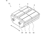
- FIG. 2 is a perspective view of the magnet module according to this embodiment.
- the direction indicated by the double-ended arrow is the rotation direction of the rotating shaft 41 of the magnetic wave gear device 1 shown in FIG.
- the magnet module 52 has a base 6 and two rotor magnets 7 and 8 having different polarities and arranged on the outer peripheral surface of the base 6 with a gap in the rotational direction.
- the base 6 has a plurality of electromagnetic steel sheets 61 laminated in the axial direction of the rotating shaft.
- a plurality of electromagnetic steel plates 61 are fixed by a bottom plate 62 having an L-shaped cross section, an end plate 63 and a fixing bolt 64 .
- the two rotor magnets 7, 8 have different poles. For example, if the outer circumference of the rotor magnet 7 is the north pole, the outer circumference of the rotor magnet 8 is the south pole. As shown in FIG. 2, the two rotor magnets 7 and 8 are each composed of four magnet pieces divided into two in the rotational direction and the axial direction. These magnet pieces are firmly fixed to the base 6 with, for example, an adhesive.
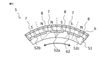
- FIG. 3 is a cross-sectional view of the high-speed rotor according to this embodiment.
- the magnet modules 52 are annularly arranged in close contact with the outer peripheral surface of the cylindrical high-speed rotor core 51 .
- FIG. 3 shows a part of the cross-section of the high-speed rotor 5 with the magnet modules 52 arranged in the direction of rotation of the rotary shaft 41 .
- the direction indicated by the double-ended arrow is the rotation direction of the rotating shaft 41 of the magnetic wave gear device 1 shown in FIG.
- the facing rotor magnets of the magnet modules 52 that are rotationally adjacent have the same pole and are in close contact with each other.
- one magnetic pole is configured to straddle two magnet modules 52 .
- dashed lines indicate boundaries of magnetic poles.
- the left N-pole rotor magnet 7 of the centrally arranged magnet module 52a and the right N-pole rotor magnet 8 of the left-hand magnet module 52b constitute one N-pole magnetic pole.
- the rotor magnet 8 of the south pole on the right side of the magnet module 52a arranged in the center and the rotor magnet 7 of the left south pole of the magnet module 52c arranged on the right side form one magnetic pole of the south pole. It is configured.
- the boundary of the magnetic poles is the central portion of the magnet module. Therefore, since the base of the magnet module serves as a magnetic path between the magnetic poles, the magnetic resistance between the magnetic poles is reduced. As a result, it is possible to suppress a decrease in the output of a magnetic wave gear device using this high-speed rotor.
- the base of the magnet module is made of magnetic steel sheets laminated in the axial direction, the current path in the axial direction is cut off, making it difficult for eddy currents to flow. Therefore, in this magnet module, eddy current loss caused by harmonic magnetic flux can be reduced.
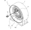
- FIG. 4 is a perspective view of the magnetic wave gear device according to this embodiment.
- the low speed rotor end plate 42 is constructed with a plurality of spokes 42a. Openings are provided between the plurality of spokes 42a.
- the magnet module 52 can also be passed through this opening and arranged on the outer peripheral surface of the high-speed rotor core 51 .
- the rotor magnets 7 and 8 are not incorporated in the high-speed rotor core 51 when the high-speed rotor core 51 is inserted into the inner peripheral side of the stator 3 .
- the gap between the high-speed rotor 5 and the stator 3 is widened in order to improve the efficiency of the assembly work. No need. If the gap between the high-speed rotor 5 and the stator 3 is widened, the output of the magnetic wave gear device will decrease. For this reason, in the magnetic wave gear device according to the present embodiment, it is possible to suppress the decrease in output caused by the widening of the gap between the high-speed rotor and the stator.
- the base of the magnet module is composed of laminated electromagnetic steel plates. If eddy current losses due to harmonic flux are not a concern, the base of the magnet module may be an integral magnetic body.
- the two rotor magnets 7 and 8 are composed of four magnet pieces that are divided into two in the rotational direction and the axial direction. If the rotor magnets 7 and 8 are divided into magnet pieces, the eddy current caused by the harmonic magnetic flux is less likely to flow, and the eddy current loss in the rotor magnets 7 and 8 can be reduced. However, if the eddy current loss in the rotor magnets is not a problem, each of the rotor magnets 7 and 8 may be composed of one magnet.
- Embodiment 2 a base in which a plurality of electromagnetic steel sheets are laminated is used as the base of the magnet module.
- a powdery magnetic material is used as the base of the magnet module.
- Other configurations of the magnet module are the same as those of the magnet module of the first embodiment.
- the configurations of the high-speed rotor and the magnetic wave gear device are the same as those of the first embodiment.
- powder materials such as iron and alloys of iron and nickel can be used.
- the boundary between the magnetic poles is the central portion of the magnet module. Therefore, since the base of the magnet module serves as a magnetic path between the magnetic poles, the magnetic resistance between the magnetic poles is reduced, and the reduction in the output of the magnetic wave gear device using this high-speed rotor can be suppressed.
- the base of the magnet module is made of a powdery magnetic material, the current path is cut off, making it difficult for eddy currents to flow, as in the first embodiment. Therefore, in this magnet module, eddy current loss caused by harmonic magnetic flux can be reduced.
- 1 magnetic wave gear device 2 frame, 3 stator, 4 low speed rotor, 5 high speed rotor, 6 base, 7, 8 rotor magnet, 31 stator core, 32 stator winding, 33 stator magnet, 41 rotary shaft, 42 low-speed rotor end plate, 42a spokes, 51 high-speed rotor core, 52, 52a, 52b, 52c magnet module, 61 electromagnetic steel plate, 62 bottom plate, 63 end plate, 64 fixing bolt.
Landscapes
- Engineering & Computer Science (AREA)
- Power Engineering (AREA)
- Permanent Magnet Type Synchronous Machine (AREA)
- Permanent Field Magnets Of Synchronous Machinery (AREA)
- Dynamo-Electric Clutches, Dynamo-Electric Brakes (AREA)
Abstract
Description
図1は、実施の形態1に係る磁気波動歯車装置の正面図である。本実施の形態の磁気波動歯車装置1は、円筒形状のフレーム2と、固定子3と、低速回転子4と、高速回転子5とを有している。固定子3は、周方向に複数のスロットを備えた固定子鉄心31、スロット内に配置された固定子巻線32および固定子磁石33を備えている。固定子3は、フレーム2の内周側でフレーム2に固定されている。低速回転子4は、固定子3の内周側に間隙を介して配置された円筒形状の低速回転子鉄心を有している。高速回転子5は、低速回転子4の回転軸41と同心で、低速回転子鉄心の内周側に間隙を介して配置されている。高速回転子5は、円筒形状の高速回転子鉄心51と周方向に並んで配置された磁石モジュール52とを備えている。低速回転子4は、高速回転子5より回転軸41方向の外側で低速回転子鉄心と回転軸41とを締結する低速回転子端板42を備えている。図1に示すように、本実施の形態の低速回転子端板42は、複数のスポーク42aで構成されている。複数のスポーク42aの間は開口部となっている。
実施の形態1においては、磁石モジュールの基台として複数の電磁鋼板が積層された基台を用いている。実施の形態2においては、磁石モジュールの基台として粉末状の磁性体を用いたものである。それ以外の磁石モジュールの構成は、実施の形態1の磁石モジュールの構成と同様である。また、高速回転子および磁気波動歯車装置の構成も実施の形態1と同様である。
したがって、例示されていない無数の変形例が、本願に開示される技術の範囲内において想定される。例えば、少なくとも1つの構成要素を変形する場合、追加する場合または省略する場合、さらには、少なくとも1つの構成要素を抽出し、他の実施の形態の構成要素と組み合わせる場合が含まれるものとする。
Claims (4)
- 回転軸を中心に磁石モジュールが円環状に配置された回転子であって、
前記磁石モジュールは、磁性体で構成された基台と、前記基台の外周面に前記回転軸の回転方向に隙間を介して配置された互いに極が異なる2つの回転子磁石とを有しており、回転方向に隣接する2つの前記磁石モジュール同士の対向する前記回転子磁石は、互いに同じ極でありかつ密接していることを特徴とする回転子。 - 前記基台は、前記回転軸の軸方向に積層された電磁鋼板で構成されていることを特徴とする請求項1に記載の回転子。
- 前記基台は、粉末状の磁性体で構成されていることを特徴とする請求項1に記載の回転子。
- 周方向に複数のスロットを備えた固定子鉄心、前記スロット内に配置された固定子巻線および固定子磁石を有する固定子と、
前記固定子の内周側に間隙を介して配置された第1回転子と、
前記第1回転子の回転軸と同心で、前記第1回転子の内周側に間隙を介して配置された第2回転子とを有する磁気波動歯車装置であって、
前記第2回転子が請求項1から3のいずれか1項に記載の回転子で構成されていることを特徴とする磁気波動歯車装置。
Priority Applications (5)
| Application Number | Priority Date | Filing Date | Title |
|---|---|---|---|
| US18/684,762 US20250007380A1 (en) | 2021-12-01 | 2021-01-12 | Rotor and magnetic wave gear device |
| EP21966358.0A EP4443708A4 (en) | 2021-12-01 | 2021-12-01 | ROTOR AND MAGNETIC SHAFT GEAR DEVICE |
| PCT/JP2021/044018 WO2023100274A1 (ja) | 2021-12-01 | 2021-12-01 | 回転子および磁気波動歯車装置 |
| CN202180104381.6A CN118285039A (zh) | 2021-12-01 | 2021-12-01 | 转子及磁波齿轮装置 |
| JP2023564326A JP7599584B2 (ja) | 2021-12-01 | 2021-12-01 | 回転子および磁気波動歯車装置 |
Applications Claiming Priority (1)
| Application Number | Priority Date | Filing Date | Title |
|---|---|---|---|
| PCT/JP2021/044018 WO2023100274A1 (ja) | 2021-12-01 | 2021-12-01 | 回転子および磁気波動歯車装置 |
Publications (1)
| Publication Number | Publication Date |
|---|---|
| WO2023100274A1 true WO2023100274A1 (ja) | 2023-06-08 |
Family
ID=86611725
Family Applications (1)
| Application Number | Title | Priority Date | Filing Date |
|---|---|---|---|
| PCT/JP2021/044018 Ceased WO2023100274A1 (ja) | 2021-12-01 | 2021-12-01 | 回転子および磁気波動歯車装置 |
Country Status (5)
| Country | Link |
|---|---|
| US (1) | US20250007380A1 (ja) |
| EP (1) | EP4443708A4 (ja) |
| JP (1) | JP7599584B2 (ja) |
| CN (1) | CN118285039A (ja) |
| WO (1) | WO2023100274A1 (ja) |
Citations (5)
| Publication number | Priority date | Publication date | Assignee | Title |
|---|---|---|---|---|
| JPH08505037A (ja) * | 1992-10-09 | 1996-05-28 | ヒル,ヴォルフガンク | 軟磁性部片および硬磁性部片から構成される永久磁石式電気機械 |
| JP2013106499A (ja) * | 2011-11-16 | 2013-05-30 | Aisin Seiki Co Ltd | 回転電機および回転電機のロータ |
| WO2013111335A1 (ja) * | 2012-01-27 | 2013-08-01 | 株式会社安川電機 | 回転電機 |
| JP2016135014A (ja) | 2015-01-20 | 2016-07-25 | 株式会社Ihi | 磁気波動歯車装置 |
| JP2019030063A (ja) | 2017-07-26 | 2019-02-21 | Tdk株式会社 | 磁石構造体及びモータ |
Family Cites Families (8)
| Publication number | Priority date | Publication date | Assignee | Title |
|---|---|---|---|---|
| US6956307B2 (en) * | 2004-03-08 | 2005-10-18 | Amsted Industries Incorporated | Soft magnetic composite powder metal cores |
| US8716913B2 (en) * | 2012-08-07 | 2014-05-06 | Boulder Wind Power, Inc. | Devices and methods for magnetic pole and back iron retention in electromagnetic machines |
| JP6093592B2 (ja) * | 2013-02-22 | 2017-03-08 | 株式会社Ihi | 磁気波動歯車装置 |
| EP3051668B1 (de) * | 2015-01-27 | 2017-04-26 | Siemens Aktiengesellschaft | Rotorsegment und Rotor einer elektrischen Maschine |
| WO2018062003A1 (ja) * | 2016-09-30 | 2018-04-05 | 日本電産株式会社 | 積層コアの製造方法 |
| EP3402044B1 (en) * | 2017-05-10 | 2025-12-03 | GE Renewable Technologies Wind B.V. | Magnet module and method of manufacturing same |
| CN108777521B (zh) * | 2018-07-27 | 2019-09-06 | 北京金风科创风电设备有限公司 | 磁极模块、电机转子及制造该电机转子的方法 |
| JP7361344B2 (ja) * | 2019-02-26 | 2023-10-16 | パナソニックIpマネジメント株式会社 | 磁気ギアードモータ |
-
2021
- 2021-01-12 US US18/684,762 patent/US20250007380A1/en active Pending
- 2021-12-01 EP EP21966358.0A patent/EP4443708A4/en active Pending
- 2021-12-01 WO PCT/JP2021/044018 patent/WO2023100274A1/ja not_active Ceased
- 2021-12-01 CN CN202180104381.6A patent/CN118285039A/zh not_active Withdrawn
- 2021-12-01 JP JP2023564326A patent/JP7599584B2/ja active Active
Patent Citations (5)
| Publication number | Priority date | Publication date | Assignee | Title |
|---|---|---|---|---|
| JPH08505037A (ja) * | 1992-10-09 | 1996-05-28 | ヒル,ヴォルフガンク | 軟磁性部片および硬磁性部片から構成される永久磁石式電気機械 |
| JP2013106499A (ja) * | 2011-11-16 | 2013-05-30 | Aisin Seiki Co Ltd | 回転電機および回転電機のロータ |
| WO2013111335A1 (ja) * | 2012-01-27 | 2013-08-01 | 株式会社安川電機 | 回転電機 |
| JP2016135014A (ja) | 2015-01-20 | 2016-07-25 | 株式会社Ihi | 磁気波動歯車装置 |
| JP2019030063A (ja) | 2017-07-26 | 2019-02-21 | Tdk株式会社 | 磁石構造体及びモータ |
Non-Patent Citations (1)
| Title |
|---|
| See also references of EP4443708A4 |
Also Published As
| Publication number | Publication date |
|---|---|
| EP4443708A4 (en) | 2025-01-15 |
| EP4443708A1 (en) | 2024-10-09 |
| CN118285039A (zh) | 2024-07-02 |
| JP7599584B2 (ja) | 2024-12-13 |
| JPWO2023100274A1 (ja) | 2023-06-08 |
| US20250007380A1 (en) | 2025-01-02 |
Similar Documents
| Publication | Publication Date | Title |
|---|---|---|
| EP2200154B1 (en) | Axial gap motor | |
| EP2226924B1 (en) | Motor and rotor for dynamo-electric machine | |
| EP2448089A1 (en) | Axial motor | |
| JP5210150B2 (ja) | 永久磁石式回転電機、エレベータ装置、及び永久磁石式回転電機の製造方法 | |
| CN108696019B (zh) | 用于开关型磁阻电机的转子的端板 | |
| JP2010178472A (ja) | アキシャルギャップ型モータ | |
| CN101663806A (zh) | 轴向间隙型电机 | |
| AU2011303910A1 (en) | Rotor for modulated pole machine | |
| EP3062419A1 (en) | Rotor for rotary electric machine | |
| WO2022118598A1 (ja) | 磁気ギアードモータ及び磁気ギア | |
| EP1528659A2 (en) | Magnetic circuit structure for rotary electric machine | |
| JPWO2020194390A1 (ja) | 回転電機 | |
| WO2015068846A1 (ja) | 回転電機 | |
| JP7317267B1 (ja) | 回転装置 | |
| JP7262623B2 (ja) | 固定子およびこれを用いた回転電機 | |
| JP5292953B2 (ja) | アキシャルギャップ型モータ | |
| JP7599584B2 (ja) | 回転子および磁気波動歯車装置 | |
| JP5731055B1 (ja) | アウターロータ型発電機 | |
| JP7527493B2 (ja) | 磁気波動歯車装置 | |
| US20240235360A1 (en) | Magnetic geared rotating machine, power generation system, and drive system | |
| JP5017045B2 (ja) | アキシャルギャップ型モータ | |
| JP5280788B2 (ja) | アキシャルギャップ型モータ | |
| JP2016178816A (ja) | ロータ、電動モータ | |
| JP2023174598A (ja) | 回転電気機械の回転子 | |
| JP6804699B1 (ja) | 固定子およびこれを用いた回転電機 |
Legal Events
| Date | Code | Title | Description |
|---|---|---|---|
| 121 | Ep: the epo has been informed by wipo that ep was designated in this application |
Ref document number: 21966358 Country of ref document: EP Kind code of ref document: A1 |
|
| WWE | Wipo information: entry into national phase |
Ref document number: 2023564326 Country of ref document: JP |
|
| WWE | Wipo information: entry into national phase |
Ref document number: 18684762 Country of ref document: US |
|
| WWE | Wipo information: entry into national phase |
Ref document number: 202180104381.6 Country of ref document: CN |
|
| NENP | Non-entry into the national phase |
Ref country code: DE |
|
| ENP | Entry into the national phase |
Ref document number: 2021966358 Country of ref document: EP Effective date: 20240701 |