WO2023100453A1 - 電極ユニット製造装置、及び、電極ユニット製造方法 - Google Patents
電極ユニット製造装置、及び、電極ユニット製造方法 Download PDFInfo
- Publication number
- WO2023100453A1 WO2023100453A1 PCT/JP2022/035717 JP2022035717W WO2023100453A1 WO 2023100453 A1 WO2023100453 A1 WO 2023100453A1 JP 2022035717 W JP2022035717 W JP 2022035717W WO 2023100453 A1 WO2023100453 A1 WO 2023100453A1
- Authority
- WO
- WIPO (PCT)
- Prior art keywords
- electrode
- resin member
- resin
- current collector
- welding
- Prior art date
- Legal status (The legal status is an assumption and is not a legal conclusion. Google has not performed a legal analysis and makes no representation as to the accuracy of the status listed.)
- Ceased
Links
Images



Classifications
-
- H—ELECTRICITY
- H01—ELECTRIC ELEMENTS
- H01G—CAPACITORS; CAPACITORS, RECTIFIERS, DETECTORS, SWITCHING DEVICES, LIGHT-SENSITIVE OR TEMPERATURE-SENSITIVE DEVICES OF THE ELECTROLYTIC TYPE
- H01G13/00—Apparatus specially adapted for manufacturing capacitors; Processes specially adapted for manufacturing capacitors not provided for in groups H01G4/00 - H01G11/00
-
- H—ELECTRICITY
- H01—ELECTRIC ELEMENTS
- H01M—PROCESSES OR MEANS, e.g. BATTERIES, FOR THE DIRECT CONVERSION OF CHEMICAL ENERGY INTO ELECTRICAL ENERGY
- H01M4/00—Electrodes
- H01M4/02—Electrodes composed of, or comprising, active material
- H01M4/04—Processes of manufacture in general
- H01M4/0402—Methods of deposition of the material
-
- H—ELECTRICITY
- H01—ELECTRIC ELEMENTS
- H01M—PROCESSES OR MEANS, e.g. BATTERIES, FOR THE DIRECT CONVERSION OF CHEMICAL ENERGY INTO ELECTRICAL ENERGY
- H01M10/00—Secondary cells; Manufacture thereof
- H01M10/05—Accumulators with non-aqueous electrolyte
- H01M10/058—Construction or manufacture
-
- B—PERFORMING OPERATIONS; TRANSPORTING
- B29—WORKING OF PLASTICS; WORKING OF SUBSTANCES IN A PLASTIC STATE IN GENERAL
- B29C—SHAPING OR JOINING OF PLASTICS; SHAPING OF MATERIAL IN A PLASTIC STATE, NOT OTHERWISE PROVIDED FOR; AFTER-TREATMENT OF THE SHAPED PRODUCTS, e.g. REPAIRING
- B29C65/00—Joining or sealing of preformed parts, e.g. welding of plastics materials; Apparatus therefor
- B29C65/02—Joining or sealing of preformed parts, e.g. welding of plastics materials; Apparatus therefor by heating, with or without pressure
-
- B—PERFORMING OPERATIONS; TRANSPORTING
- B29—WORKING OF PLASTICS; WORKING OF SUBSTANCES IN A PLASTIC STATE IN GENERAL
- B29C—SHAPING OR JOINING OF PLASTICS; SHAPING OF MATERIAL IN A PLASTIC STATE, NOT OTHERWISE PROVIDED FOR; AFTER-TREATMENT OF THE SHAPED PRODUCTS, e.g. REPAIRING
- B29C65/00—Joining or sealing of preformed parts, e.g. welding of plastics materials; Apparatus therefor
- B29C65/72—Joining or sealing of preformed parts, e.g. welding of plastics materials; Apparatus therefor by combined operations or combined techniques, e.g. welding and stitching
-
- B—PERFORMING OPERATIONS; TRANSPORTING
- B29—WORKING OF PLASTICS; WORKING OF SUBSTANCES IN A PLASTIC STATE IN GENERAL
- B29C—SHAPING OR JOINING OF PLASTICS; SHAPING OF MATERIAL IN A PLASTIC STATE, NOT OTHERWISE PROVIDED FOR; AFTER-TREATMENT OF THE SHAPED PRODUCTS, e.g. REPAIRING
- B29C65/00—Joining or sealing of preformed parts, e.g. welding of plastics materials; Apparatus therefor
- B29C65/78—Means for handling the parts to be joined, e.g. for making containers or hollow articles, e.g. means for handling sheets, plates, web-like materials, tubular articles, hollow articles or elements to be joined therewith; Means for discharging the joined articles from the joining apparatus
- B29C65/7841—Holding or clamping means for handling purposes
- B29C65/7847—Holding or clamping means for handling purposes using vacuum to hold at least one of the parts to be joined
-
- B—PERFORMING OPERATIONS; TRANSPORTING
- B29—WORKING OF PLASTICS; WORKING OF SUBSTANCES IN A PLASTIC STATE IN GENERAL
- B29C—SHAPING OR JOINING OF PLASTICS; SHAPING OF MATERIAL IN A PLASTIC STATE, NOT OTHERWISE PROVIDED FOR; AFTER-TREATMENT OF THE SHAPED PRODUCTS, e.g. REPAIRING
- B29C66/00—General aspects of processes or apparatus for joining preformed parts
- B29C66/01—General aspects dealing with the joint area or with the area to be joined
- B29C66/05—Particular design of joint configurations
- B29C66/10—Particular design of joint configurations particular design of the joint cross-sections
- B29C66/11—Joint cross-sections comprising a single joint-segment, i.e. one of the parts to be joined comprising a single joint-segment in the joint cross-section
- B29C66/112—Single lapped joints
- B29C66/1122—Single lap to lap joints, i.e. overlap joints
-
- B—PERFORMING OPERATIONS; TRANSPORTING
- B29—WORKING OF PLASTICS; WORKING OF SUBSTANCES IN A PLASTIC STATE IN GENERAL
- B29C—SHAPING OR JOINING OF PLASTICS; SHAPING OF MATERIAL IN A PLASTIC STATE, NOT OTHERWISE PROVIDED FOR; AFTER-TREATMENT OF THE SHAPED PRODUCTS, e.g. REPAIRING
- B29C66/00—General aspects of processes or apparatus for joining preformed parts
- B29C66/40—General aspects of joining substantially flat articles, e.g. plates, sheets or web-like materials; Making flat seams in tubular or hollow articles; Joining single elements to substantially flat surfaces
- B29C66/41—Joining substantially flat articles ; Making flat seams in tubular or hollow articles
- B29C66/43—Joining a relatively small portion of the surface of said articles
- B29C66/431—Joining the articles to themselves
- B29C66/4312—Joining the articles to themselves for making flat seams in tubular or hollow articles, e.g. transversal seams
-
- B—PERFORMING OPERATIONS; TRANSPORTING
- B29—WORKING OF PLASTICS; WORKING OF SUBSTANCES IN A PLASTIC STATE IN GENERAL
- B29C—SHAPING OR JOINING OF PLASTICS; SHAPING OF MATERIAL IN A PLASTIC STATE, NOT OTHERWISE PROVIDED FOR; AFTER-TREATMENT OF THE SHAPED PRODUCTS, e.g. REPAIRING
- B29C66/00—General aspects of processes or apparatus for joining preformed parts
- B29C66/80—General aspects of machine operations or constructions and parts thereof
- B29C66/83—General aspects of machine operations or constructions and parts thereof characterised by the movement of the joining or pressing tools
- B29C66/832—Reciprocating joining or pressing tools
- B29C66/8322—Joining or pressing tools reciprocating along one axis
- B29C66/83221—Joining or pressing tools reciprocating along one axis cooperating reciprocating tools, each tool reciprocating along one axis
-
- H—ELECTRICITY
- H01—ELECTRIC ELEMENTS
- H01G—CAPACITORS; CAPACITORS, RECTIFIERS, DETECTORS, SWITCHING DEVICES, LIGHT-SENSITIVE OR TEMPERATURE-SENSITIVE DEVICES OF THE ELECTROLYTIC TYPE
- H01G11/00—Hybrid capacitors, i.e. capacitors having different positive and negative electrodes; Electric double-layer [EDL] capacitors; Processes for the manufacture thereof or of parts thereof
- H01G11/84—Processes for the manufacture of hybrid or EDL capacitors, or components thereof
- H01G11/86—Processes for the manufacture of hybrid or EDL capacitors, or components thereof specially adapted for electrodes
-
- H—ELECTRICITY
- H01—ELECTRIC ELEMENTS
- H01M—PROCESSES OR MEANS, e.g. BATTERIES, FOR THE DIRECT CONVERSION OF CHEMICAL ENERGY INTO ELECTRICAL ENERGY
- H01M10/00—Secondary cells; Manufacture thereof
- H01M10/04—Construction or manufacture in general
-
- H—ELECTRICITY
- H01—ELECTRIC ELEMENTS
- H01M—PROCESSES OR MEANS, e.g. BATTERIES, FOR THE DIRECT CONVERSION OF CHEMICAL ENERGY INTO ELECTRICAL ENERGY
- H01M10/00—Secondary cells; Manufacture thereof
- H01M10/04—Construction or manufacture in general
- H01M10/0404—Machines for assembling batteries
-
- H—ELECTRICITY
- H01—ELECTRIC ELEMENTS
- H01M—PROCESSES OR MEANS, e.g. BATTERIES, FOR THE DIRECT CONVERSION OF CHEMICAL ENERGY INTO ELECTRICAL ENERGY
- H01M10/00—Secondary cells; Manufacture thereof
- H01M10/04—Construction or manufacture in general
- H01M10/0413—Large-sized flat cells or batteries for motive or stationary systems with plate-like electrodes
- H01M10/0418—Large-sized flat cells or batteries for motive or stationary systems with plate-like electrodes with bipolar electrodes
-
- H—ELECTRICITY
- H01—ELECTRIC ELEMENTS
- H01M—PROCESSES OR MEANS, e.g. BATTERIES, FOR THE DIRECT CONVERSION OF CHEMICAL ENERGY INTO ELECTRICAL ENERGY
- H01M10/00—Secondary cells; Manufacture thereof
- H01M10/04—Construction or manufacture in general
- H01M10/0436—Small-sized flat cells or batteries for portable equipment
- H01M10/044—Small-sized flat cells or batteries for portable equipment with bipolar electrodes
-
- H—ELECTRICITY
- H01—ELECTRIC ELEMENTS
- H01M—PROCESSES OR MEANS, e.g. BATTERIES, FOR THE DIRECT CONVERSION OF CHEMICAL ENERGY INTO ELECTRICAL ENERGY
- H01M10/00—Secondary cells; Manufacture thereof
- H01M10/04—Construction or manufacture in general
- H01M10/0486—Frames for plates or membranes
-
- H—ELECTRICITY
- H01—ELECTRIC ELEMENTS
- H01M—PROCESSES OR MEANS, e.g. BATTERIES, FOR THE DIRECT CONVERSION OF CHEMICAL ENERGY INTO ELECTRICAL ENERGY
- H01M10/00—Secondary cells; Manufacture thereof
- H01M10/05—Accumulators with non-aqueous electrolyte
- H01M10/052—Li-accumulators
- H01M10/0525—Rocking-chair batteries, i.e. batteries with lithium insertion or intercalation in both electrodes; Lithium-ion batteries
-
- H—ELECTRICITY
- H01—ELECTRIC ELEMENTS
- H01M—PROCESSES OR MEANS, e.g. BATTERIES, FOR THE DIRECT CONVERSION OF CHEMICAL ENERGY INTO ELECTRICAL ENERGY
- H01M4/00—Electrodes
- H01M4/02—Electrodes composed of, or comprising, active material
- H01M4/04—Processes of manufacture in general
- H01M4/0471—Processes of manufacture in general involving thermal treatment, e.g. firing, sintering, backing particulate active material, thermal decomposition, pyrolysis
-
- B—PERFORMING OPERATIONS; TRANSPORTING
- B29—WORKING OF PLASTICS; WORKING OF SUBSTANCES IN A PLASTIC STATE IN GENERAL
- B29L—INDEXING SCHEME ASSOCIATED WITH SUBCLASS B29C, RELATING TO PARTICULAR ARTICLES
- B29L2031/00—Other particular articles
- B29L2031/34—Electrical apparatus, e.g. sparking plugs or parts thereof
- B29L2031/3468—Batteries, accumulators or fuel cells
-
- H—ELECTRICITY
- H01—ELECTRIC ELEMENTS
- H01M—PROCESSES OR MEANS, e.g. BATTERIES, FOR THE DIRECT CONVERSION OF CHEMICAL ENERGY INTO ELECTRICAL ENERGY
- H01M4/00—Electrodes
- H01M4/02—Electrodes composed of, or comprising, active material
- H01M2004/026—Electrodes composed of, or comprising, active material characterised by the polarity
- H01M2004/029—Bipolar electrodes
-
- Y—GENERAL TAGGING OF NEW TECHNOLOGICAL DEVELOPMENTS; GENERAL TAGGING OF CROSS-SECTIONAL TECHNOLOGIES SPANNING OVER SEVERAL SECTIONS OF THE IPC; TECHNICAL SUBJECTS COVERED BY FORMER USPC CROSS-REFERENCE ART COLLECTIONS [XRACs] AND DIGESTS
- Y02—TECHNOLOGIES OR APPLICATIONS FOR MITIGATION OR ADAPTATION AGAINST CLIMATE CHANGE
- Y02E—REDUCTION OF GREENHOUSE GAS [GHG] EMISSIONS, RELATED TO ENERGY GENERATION, TRANSMISSION OR DISTRIBUTION
- Y02E60/00—Enabling technologies; Technologies with a potential or indirect contribution to GHG emissions mitigation
- Y02E60/10—Energy storage using batteries
Definitions
- the present disclosure is an electrode unit manufacturing apparatus and an electrode unit manufacturing method.
- Patent Document 1 discloses a method of forming a bipolar electrode unit by welding a resin frame to a bipolar electrode.
- the bipolar electrode and the resin frame are transported between a pair of pressure members adjusted to a predetermined clearance in a state in which the resin frame is temporarily fixed to the first surface of the electrode plate of the bipolar electrode. be.
- the electrode plate of the bipolar electrode and the resin frame are heated by the heater and pressed by the pressing roller, and then cooled by the cooling plate.
- the resin frame is welded to the electrode plate of the bipolar electrode to form a bipolar electrode unit.
- the electrode at each stage is placed on a stage or a pallet. It is conceivable to perform welding in the state.
- the electrodes are placed on the stage or the pallet in this way, there is a risk that foreign substances such as metal pieces of the current collectors constituting the electrodes and the active material of the active material layer, which have slipped down from the electrodes, may adhere to the stage or the pallet and remain there. be. Therefore, in this case, when the next electrode is placed on the stage or pallet, foreign matter may adhere to the electrode.
- an object of the present disclosure is to provide an electrode unit manufacturing apparatus and an electrode unit manufacturing method capable of welding resin members while suppressing adhesion of foreign matter to electrodes.
- An electrode unit manufacturing apparatus is an electrode unit manufacturing apparatus for manufacturing an electrode unit by welding a resin member to an electrode including a current collector and an active material layer provided on the surface of the current collector. and a welding device including a welding unit that welds a resin member to the electrode suction-held in the air by the transfer unit.
- An electrode unit manufacturing method is a method for manufacturing an electrode unit by welding a resin member to an electrode including a current collector and an active material layer provided on the surface of the current collector. a first step of conveying the electrode in the air while adsorbing and holding the electrode; and a second step of welding the resin member to the electrode held in the air after the first step.
- the welding device includes a placement unit that holds the resin member before being welded to the electrode, and that places the resin member on the surface of the electrode that is held by suction in the air on the conveying unit. and the welding part may weld the resin member arranged on the surface by the arrangement part to the current collector.
- a resin member is arranged and welded to the surface of the current collector of the electrode. Therefore, it is possible to prevent the foreign matter slipping down from the electrode from adhering to the next electrode, thereby preventing the foreign matter from intervening between the electrode and the resin member when the resin members are arranged and welded.
- the welding device includes a first gripping portion that pulls out the base material from the holding portion by moving while gripping one end of the base material held by the holding portion; a second gripping portion that further grips the base material pulled out by the movement of the first gripping portion at a position spaced apart from the first gripping portion; and a cutting portion that forms the resin member by cutting.
- the resin member can be easily formed from the base material.
- the welding device includes a sensor for detecting the resin member held by the first holding portion and the second holding portion, and a sensor for detecting the resin member held by the placement portion.
- a moving unit that aligns the resin member based on the detection result of the sensor by moving the first gripping portion and the second gripping portion may be included. In this case, the positional accuracy of the resin member with respect to the welding position is improved.
- the first gripping part moves while gripping the pair of base materials stacked and held in the holding part, thereby pulling out the pair of base materials from the holding part
- the gripping portion further grips the pair of base materials pulled out by the movement of the first gripping portion at a position spaced apart from the first gripping portion, and the cutting portion cuts the pair of base materials to cut the pair of resins.
- the arranging section changes the gap between the pair of resin members by moving in the stacking direction of the resin members while holding at least one of the pair of resin members, and the conveying section moves the arranging section to
- the electrode is conveyed so that the current collector is sandwiched between the pair of resin members with an enlarged gap, and the welding portion is formed such that the pair of resin members is placed between the surface of the current collector and the current collector by moving the placement portion.
- Each of the pair of resin members may be welded to the current collector while being arranged on the back surface opposite to the surface of the current collector.
- a pair of resin members are formed for each of the front and back surfaces of the current collector by pulling out the base material once by the first gripping portion and cutting the base material once by the cutting portion. It becomes possible to weld.
- the welding device includes a sensor that detects the resin member held by the placement section, and a sensor that detects the resin member by moving the placement section while the resin member is held by the placement section. and a moving unit that aligns the resin member based on the detection result of. In this case, the positional accuracy of the resin member with respect to the welding position is improved.
- an electrode unit manufacturing apparatus and an electrode unit manufacturing method capable of welding a resin member while suppressing adhesion of foreign matter to electrodes.
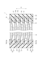
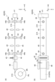
- FIG. 1 is a schematic cross-sectional view of a power storage module according to this embodiment.
- FIG. 2 is a diagram showing an example of an electrode unit.
- FIG. 3 is a schematic diagram showing part of the electrode unit manufacturing apparatus.
- FIG. 4 is a schematic diagram showing another part of the electrode unit manufacturing apparatus.
- FIG. 5 is a schematic diagram showing another part of the electrode unit manufacturing apparatus.
- FIG. 6 is a flow chart showing one step of the electrode unit manufacturing method.
- FIG. 7 is a side view showing one step of the electrode unit manufacturing method.
- FIG. 8 is a diagram showing a modification of the welding device.
- FIG. 1 is a schematic cross-sectional view of a power storage module according to this embodiment.
- a power storage module 1 shown in FIG. 1 is, for example, a power storage module used in batteries of various vehicles such as forklifts, hybrid vehicles, and electric vehicles.
- the power storage module 1 is, for example, a secondary battery such as a nickel-hydrogen secondary battery or a lithium-ion secondary battery.
- the power storage module 1 may be an electric double layer capacitor or an all-solid battery.
- the case where the electric storage module 1 is a lithium ion secondary battery is illustrated.
- the power storage module 1 includes a laminate 10 and a resin frame 22 .
- the laminate 10 includes a plurality of bipolar electrodes 11, a negative electrode terminal electrode 12, a positive electrode terminal electrode 13, a plurality of separators 14, a plurality of first resin layers 21 and a plurality of second resin layers 23, and an electrolyte (non-conductive). shown).
- the bipolar electrode 11 has a current collector 15 , a positive electrode active material layer 16 and a negative electrode active material layer 17 .
- the current collector 15 has, for example, a rectangular sheet shape.
- the positive electrode active material layer 16 is provided on one surface 15 a of the current collector 15 .
- the negative electrode active material layer 17 is provided on the other surface 15 b of the current collector 15 .
- the plurality of bipolar electrodes 11 are stacked such that the positive electrode active material layer 16 of one bipolar electrode 11 and the negative electrode active material layer 17 of another bipolar electrode 11 face each other.
- the direction in which the bipolar electrodes 11 are stacked is called a stacking direction D. As shown in FIG.
- the positive electrode active material layer 16 and the negative electrode active material layer 17 are rectangular when viewed from the stacking direction D.
- the negative electrode active material layer 17 is one size larger than the positive electrode active material layer 16 when viewed in the stacking direction D. As shown in FIG. That is, in a plan view in the stacking direction D, the entire forming region of the positive electrode active material layer 16 is located within the forming region of the negative electrode active material layer 17 .
- the negative terminal electrode 12 has a current collector 15 and a negative electrode active material layer 17 provided on the other surface 15 b of the current collector 15 .
- the negative terminal electrode 12 does not have the positive electrode active material layer 16 . That is, the active material layer is not provided on the one surface 15a of the current collector 15 of the negative terminal electrode 12 .
- the negative terminal electrode 12 is stacked on the bipolar electrode 11 at one end in the stacking direction D of the stack 10 .
- the negative terminal electrode 12 is laminated on the bipolar electrode 11 such that the negative electrode active material layer 17 faces the positive electrode active material layer 16 of the bipolar electrode 11 . Therefore, one surface 15 a of the current collector 15 of the negative terminal electrode 12 faces the outside of the laminate 10 and is partly exposed outside the laminate 10 .
- the positive terminal electrode 13 has a current collector 15 and a positive electrode active material layer 16 provided on one surface 15 a of the current collector 15 .
- the positive terminal electrode 13 does not have the negative electrode active material layer 17 . That is, no active material layer is provided on the other surface 15b of the current collector 15 of the positive terminal electrode 13 .
- the positive terminal electrode 13 is stacked on the bipolar electrode 11 at the other end of the stack 10 in the stacking direction D. As shown in FIG. Positive terminal electrode 13 is stacked on bipolar electrode 11 such that positive electrode active material layer 16 faces negative electrode active material layer 17 of bipolar electrode 11 . Therefore, the other surface 15 b of the current collector 15 of the positive terminal electrode 13 faces the outside of the laminate 10 and is partially exposed outside the laminate 10 .
- the separators 14 are arranged between the adjacent bipolar electrodes 11 , between the negative terminal electrode 12 and the bipolar electrode 11 , and between the positive terminal electrode 13 and the bipolar electrode 11 .
- the separator 14 is interposed between the positive electrode active material layer 16 and the negative electrode active material layer 17 .
- the separator 14 separates the positive electrode active material layer 16 from the negative electrode active material layer 17, thereby preventing short circuits due to contact between adjacent electrodes and allowing charge carriers such as lithium ions to pass through.
- the current collector 15 is a chemically inactive electrical conductor for continuing current flow through the positive electrode active material layer 16 and the negative electrode active material layer 17 during discharging or charging of the lithium ion secondary battery.
- the material of the current collector 15 is, for example, a metal material, a conductive resin material, or a conductive inorganic material.
- the conductive resin material include a resin obtained by adding a conductive filler to a conductive polymer material or a non-conductive polymer material as necessary.
- the current collector 15 may comprise multiple layers. In this case, each layer of the current collector 15 may contain the above metal material or conductive resin material.
- a coating layer may be formed on the surface of the current collector 15 .
- the coating layer may be formed by a known method such as plating or spray coating.
- the current collector 15 may have, for example, a plate shape, a foil shape (for example, a metal foil), a film shape, a mesh shape, or the like.
- metal foil include aluminum foil, copper foil, nickel foil, titanium foil, stainless steel foil, and the like.
- Stainless steel foils include, for example, SUS 304, SUS 316, SUS 301, etc. specified in JIS G 4305:2015.
- the current collector 15 may be an alloy foil of the above metals or a foil in which a plurality of the above metal foils are integrated.
- the thickness of the current collector 15 may be, for example, 1 ⁇ m to 100 ⁇ m.
- the positive electrode active material layer 16 contains a positive electrode active material capable of intercalating and deintercalating charge carriers such as lithium ions.
- positive electrode active materials include lithium composite metal oxides having a layered rock salt structure, metal oxides having a spinel structure, and polyanionic compounds. Any positive electrode active material may be used as long as it can be used in a lithium ion secondary battery.
- the positive electrode active material layer 16 may contain a plurality of positive electrode active materials.
- the positive electrode active material layer 16 contains olivine-type lithium iron phosphate (LiFePO 4 ) as a composite oxide.
- the negative electrode active material layer 17 contains a negative electrode active material capable of intercalating and deintercalating charge carriers such as lithium ions.
- the negative electrode active material may be a simple substance, an alloy, or a compound.
- Examples of negative electrode active materials include Li, carbon, and metal compounds.
- the negative electrode active material may be an element that can be alloyed with lithium, a compound thereof, or the like.
- Examples of carbon include natural graphite, artificial graphite, hard carbon (non-graphitizable carbon), soft carbon (easily graphitizable carbon), and the like.
- Examples of artificial graphite include highly oriented graphite and mesocarbon microbeads. Elements that can be alloyed with lithium include silicon (silicon), tin, and the like.
- the negative electrode active material layer 17 contains graphite as a carbonaceous material.
- Each of the positive electrode active material layer 16 and the negative electrode active material layer 17 contains a conductive aid, a binder, an electrolyte ( polymer matrices, ion-conducting polymers, electrolytes, etc.), electrolyte-supporting salts (lithium salts) to enhance ionic conductivity, and the like.
- a conductive aid is added to increase the conductivity of each electrode (bipolar electrode 11, negative terminal electrode 12, positive terminal electrode 13).
- the conductive aid is, for example, acetylene black, carbon black or graphite.
- Binders include fluorine-containing resins such as polyvinylidene fluoride, polytetrafluoroethylene, and fluororubber, thermoplastic resins such as polypropylene and polyethylene, imide resins such as polyimide and polyamideimide, alkoxysilyl group-containing resins, and acrylic acid.
- acrylic resins such as methacrylic acid, styrene-butadiene rubber (SBR), carboxymethyl cellulose, alginates such as sodium alginate and ammonium alginate, water-soluble cellulose ester crosslinked products, starch-acrylic acid graft polymers, and the like.
- SBR styrene-butadiene rubber
- alginates such as sodium alginate and ammonium alginate
- water-soluble cellulose ester crosslinked products starch-acrylic acid graft polymers, and the like.
- the solvent include water, N-methyl-2-pyrrolidone (NMP), and the like.
- the separator 14 may be, for example, a porous sheet or non-woven fabric containing a polymer that absorbs and retains the electrolyte.
- materials for the separator 14 include polypropylene, polyethylene, polyolefin, and polyester.
- Separator 14 may have a single-layer structure or a multi-layer structure.
- the multilayer structure may, for example, have ceramic layers or the like as adhesive layers or heat-resistant layers.
- the separator 14 may be impregnated with an electrolyte.
- the separator 14 may be composed of an electrolyte such as a polymer electrolyte or an inorganic electrolyte.
- the electrolyte impregnated in the separator 14 is, for example, a liquid electrolyte (electrolytic solution) containing a non-aqueous solvent and an electrolyte salt dissolved in the non-aqueous solvent, or a polymer gel electrolyte containing an electrolyte held in a polymer matrix. etc.
- the electrolyte salt may be LiClO 4 , LiAsF 6 , LiPF 6 , LiBF 4 , LiCF 3 SO 3 , LiN(FSO 2 ) 2 , LiN(CF 3 SO 2 ) 2 or the like.
- known lithium salts of may be used.
- nonaqueous solvent known solvents such as cyclic carbonates, cyclic esters, chain carbonates, chain esters, and ethers may be used. Two or more of these known solvent materials may be used in combination.
- the first resin layer 21 , the resin frame 22 and the second resin layer 23 constitute the sealing portion 20 .
- the sealing portion 20 is formed in a frame-like shape on the periphery of the laminate 10 so as to surround the laminate 10 .
- the sealing portion 20 is joined to each of the one surface 15a and the other surface 15b of each current collector 15 at the peripheral edge portion 15c of each current collector 15 .
- the sealing portion 20 seals each of the spaces S between the current collectors 15 adjacent to each other in the stacking direction D. As shown in FIG.
- Each space S contains an electrolyte. When the electrolyte is liquid, the sealing portion 20 prevents permeation of the electrolyte to the outside.
- the sealing portion 20 suppresses entry of moisture or the like into the space S from the outside of the laminate 10 .
- the edge of each separator 14 is embedded in the sealing portion 20 .
- the sealing portion 20 contains an insulating material.
- materials for the sealing portion 20 include various resin materials such as polypropylene, polyethylene, polystyrene, ABS resin, modified polypropylene, and acrylonitrile-styrene resin.
- the first resin layer 21 is provided on each current collector 15 . Therefore, the first resin layers 21 are stacked together along the stacking direction D. As shown in FIG.
- the first resin layer 21 has a frame shape and is provided on the peripheral portion 15 c of the current collector 15 . That is, the first resin layer 21 is provided so as to extend from the one surface 15a of the current collector 15 to the other surface 15b via the end surface, and covers the peripheral edge portion 15c.
- the first resin layer 21 is welded to the one surface 15 a and the other surface 15 b of the current collector 15 .
- the second resin layers 23 are arranged so as to be interposed between the first resin layers 21 adjacent in the stacking direction D. Thereby, the second resin layer 23 holds a space between adjacent first resin layers 21 , that is, between adjacent current collectors 15 .
- the second resin layer 23 has a frame shape and is arranged on the peripheral edge portion 15 c of the current collector 15 when viewed from the stacking direction D. As shown in FIG.
- the second resin layer 23 can be welded to at least one of the pair of first resin layers 21 adjacent in the stacking direction D.
- the ends of the separator 14 are embedded between the first resin layer 21 and the second resin layer 23 .
- the resin frame 22 is formed by integrating multiple first resin layers 21 and multiple second resin layers 23 .
- the end portion of the first resin layer 21 opposite to the space S and the end portion of the second resin layer 23 opposite to the space S are welded to each other, so that the plurality of spaces S are collectively formed. and sealed.
- the surface of the resin frame 22 opposite to the space S constitutes an outer surface 10 s of the laminate 10 .
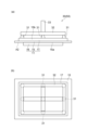
- FIG. 2 is a diagram showing an example of an electrode unit.
- FIG. 2(a) is a cross-sectional view
- FIG. 2(b) is a plan view.
- FIG. 2 illustrates an electrode unit 11A including bipolar electrodes 11.
- Electrode unit 11A includes bipolar electrode 11 and first resin layer 21 welded to bipolar electrode 11 .
- One surface (front surface) 15a and the other surface (back surface) 15b of the current collector 15 include a first region A1 in which an active material layer (positive electrode active material layer 16 and negative electrode active material layer 17) is formed, and and an exposed second region A2.
- the first resin layer 21 is welded to each of the one surface 15a and the other surface 15b of the current collector 15 in the second region A2.
- FIG. 2 shows the electrode unit 11A including the bipolar electrode 11
- the power storage module 1 also includes an electrode unit including the positive terminal electrode 13 and an electrode unit including the negative terminal electrode 12.
- the electrode unit including the positive terminal electrode 13 is different from the electrode unit 11A only in that the negative electrode active material layer 17 is not formed on the other surface 15b of the current collector 15, and the negative terminal electrode is different from the electrode unit 11A.
- the electrode unit including 12 is different only in that the positive electrode active material layer 16 is not formed on one surface 15a of the current collector 15, and is otherwise common.
- the laminate 10 is configured by laminating a plurality of the electrode units described above with the second resin layer 23 and the separator 14 interposed therebetween. Taking the electrode unit 11A as an example, an electrode unit manufacturing apparatus and an electrode unit manufacturing method will be described below.
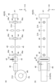
- FIG. 3 is a schematic diagram showing part of the electrode unit manufacturing apparatus.
- FIG. 3(a) is a side view
- FIG. 3(b) is a plan view.
- the electrode unit manufacturing apparatus 50 includes a robot hand (conveyor) 30 .
- the robot hand 30 includes a plurality of suction pads 31 , an air pipe 32 and a support portion 33 .
- the robot hand 30 is connected to a drive section (not shown) via a support section 33, and is three-dimensionally movable by the drive section.
- the plurality of suction pads 31 are arranged apart from each other.
- the negative electrode active material layer 17 (or the positive electrode active material layer 16, hereinafter sometimes simply referred to as “active material layer”) is arranged to face the robot hand 30, the plurality of suction pads 31 are arranged on the same plane. are arranged so as to be dispersed throughout the active material layer.
- the air pipe 32 is connected to each of the suction pads 31 .
- the air pipe 32 performs suction and exhaust in the plurality of suction pads 31 , thereby causing a member (for example, the negative electrode active material layer 17 ) arranged opposite to the plurality of suction pads 31 to be adsorbed to the suction pads 31 .
- a member for example, the negative electrode active material layer 17
- the support portion 33 is connected to the air pipe 32 and supports the air pipe 32 and the suction pad 31 on the robot hand 30 .
- a pipe leading to the air pipe 32 may be provided inside the support portion 33 .
- the adsorption pad 31 is adsorbed to the active material layer, so that the bipolar electrode 11 can be transported in the air to an arbitrary position while adsorbing and holding the bipolar electrode 11.
- the transfer by the robot hand 30 is performed so that the surface of the bipolar electrode 11 to which the suction pad 31 sucks is the upper surface in the vertical direction (the direction of gravity).
- the aerial transport here means transport in a state where the surface of the bipolar electrode 11 opposite to the surface adsorbed by the adsorption pad 31 is not in contact with or supported by another device or member.
- the plurality of suction pads 31 are distributed over the entire active material layer. Therefore, when the robot hand 30 sucks and holds the bipolar electrode 11, the warp of the bipolar electrode 11 is suppressed.
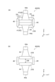
- FIG. 4 and 5 are schematic diagrams showing another part of the electrode unit manufacturing apparatus.
- the following figures show a Cartesian coordinate system consisting of an X-axis, a Y-axis and a Z-axis.
- the X-axis direction and the Y-axis direction are the first horizontal direction and the second horizontal direction, respectively, and the Z-axis direction is the vertical direction.
- FIG. 4(a) is a side view (viewed from the Y direction)
- FIG. 4(b) is a plan view (viewed from the Z direction)
- FIG. 5 is another side view (viewed from the X direction). Figure).
- the electrode unit manufacturing device 50 includes a welding device 40.
- the welding device 40 includes a first gripping portion 41 , a second gripping portion 42 , a cutting portion 43 , a plurality of pairs of suction portions (placement portions) 44 , a plurality of pairs of welding portions 45 , moving portions 46 and 47 , and a pair of guide portions 48 . , and a plurality of sensors 49 .
- a holding part PA for holding the base material 21A for the resin member 21B is arranged in the front stage of the welding device 40 .
- the base material 21A is wound around the reel PR and held in a roll shape.
- the resin member 21B is obtained by cutting the base material 21A to an appropriate length.
- the first resin layer 21 is formed by arranging and integrating resin members 21B obtained by cutting the base material 21A in a frame shape. Therefore, in this embodiment, the resin member 21B is a member that forms part of the first resin layer 21 .
- the first gripping part 41 grips one end of the base material 21A held by the holding part PA, and is moved along the X-axis direction by the moving part 46, thereby pulling out the base material 21A from the holding part PA.
- the first gripper 41 is, for example, a chuck.
- the second gripping portion 42 further grips the base material 21A pulled out by the movement of the first gripping portion 41 at a position separated from the first gripping portion 41 (approximately by the length of the first resin layer 21).
- the second gripping portion 42 is a pair of elastic members (for example, sponges) arranged to sandwich the base material 21A along the Z direction, and can grip the base material 21A by sandwiching the base material 21A along the Z direction. can.
- the cutting part 43 is gripped by the first gripping part 41 and the second gripping part 42 by cutting the base material 21A while maintaining the state gripped by the first gripping part 41 and the second gripping part 42 .
- the first resin layer 21 is formed in a folded state.
- the cutting part 43 includes, for example, a Thomson blade, and cuts the base material 21A at the position gripped by the second gripping part 42 . Thereby, a strip-shaped resin member 21B is formed between the first gripping portion 41 and the second gripping portion 42 .
- Each of the plurality of pairs of suction portions 44 is a suction pad, and is positioned between the first gripping portion 41 and the second gripping portion 42 along the longitudinal direction (here, the X-axis direction) of the resin member 21B. distributedly arranged.
- suction part 44 is arrange
- the plurality of pairs of suction portions 44 are composed of a group of suction portions 44 arranged above the resin member 21B in the Z-axis direction (hereinafter sometimes referred to as “upper side suction portions”) and the Z and another group of suction portions 44 (hereinafter sometimes referred to as “lower suction portions”) arranged axially downward.
- Each of the adsorption portions 44 is supported by an air pipe and a support portion 44a, which is a vertical cylinder, and is movable along the Z-axis direction.
- the pair of suction portions 44 are movable such that the distance between them in the Z-axis direction changes.
- the first gripping part 41 moves while gripping the pair of base materials 21A stacked and held in the holding part PA, thereby pulling out the pair of base materials 21A superimposed on each other from the holding part PA.
- the second gripping portion 42 grips the pair of base materials 21 ⁇ /b>A pulled out by the movement of the first gripping portion 41 at a position separated from the first gripping portion 41 .
- the cutting portion 43 collectively cuts the pair of base materials 21A while maintaining the state of being gripped by the first gripping portion 41 and the second gripping portion 42, so that the pair of base materials 21A are overlapped in the Z-axis direction to form a A pair of resin members 21B that are gripped by the first gripping portion 41 and the second gripping portion 42 are collectively formed.
- one of the pair of suction portions 44 (that is, each of the upper side suction portions) faces one of the resin members 21B that are superimposed on each other, and the other of the pair of suction portions 44 (that is, each of the lower side suction portions) faces each other. ) faces the other of the mutually superimposed resin members 21B. Therefore, each of the upper adsorption portions and each of the lower adsorption portions is moved closer to the resin member 21B and brought into contact with each of the pair of resin members 21B, thereby moving each of the pair of resin members 21B. can be adsorbed.
- each of the upper adsorption portions and each of the lower adsorption portions is moved away from each other in a state in which each of the pair of resin members 21B is adsorbed, thereby reducing the gap DB between the pair of resin members 21B. It is possible to expand (it is also possible to reduce the spacing DB by being moved in the opposite direction). That is, the adsorption portion 44 moves in the stacking direction (Z-axis direction) of the resin members 21B while adsorbing at least one (here, both) of the pair of resin members 21B, thereby reducing the gap between the pair of resin members 21B. It is possible to change the DB.
- the robot hand 30 is configured with a bipolar forceps such that the second regions A2 of the one surface 15a and the other surface 15b of the current collector 15 are sandwiched between the pair of resin members 21B with the gap DB enlarged by the movement of the adsorption portion 44. Electrode 11 can be transported. Thereby, the resin member 21B is arranged with respect to the bipolar electrode 11 so that the second area A2 faces the resin member 21B. In this way, the adsorption portion 44 holds the resin member 21B before being welded to the bipolar electrode 11, and also attaches to the one surface 15a and the other surface 15b of the bipolar electrode 11 that is being adsorbed and held by the robot hand 30 in the air. It functions as an arrangement portion for arranging the resin member 21B.
- the plurality of welding parts 45 weld the resin member 21B to the bipolar electrode 11 respectively.
- the plurality of pairs of welded portions 45 are arranged in a dispersed manner in the longitudinal direction (the X-axis direction here) of the resin member 21B at positions different from the suction portions 44 .
- a pair of welding parts 45 are arranged so as to face each other along the Z-axis direction via the resin member 21B.
- the pair of welding portions 45 are arranged so as to vertically sandwich the resin member 21B.
- each of the plurality of welded portions 45 forms the one surface 15a of the current collector 15 and the other surface 15b of the current collector 15 in the second region A2 for the bipolar electrode 11 held by the robot hand 30.
- the welding unit 45 is a device that heats the resin member 21B in a contact or non-contact manner, and is configured by, for example, a soldering iron or a laser welding machine. In this way, the welding portion 45 is formed by moving the adsorption portion (placement portion) 44 so that the pair of resin members 21B are arranged on the one surface 15a and the other surface 15b of the current collector 15, respectively. Each member 21B is welded to the current collector 15 .
- the moving part 46 is provided on the first gripping part 41 and moves the first gripping part 41 .
- the moving part 47 is provided on the second grip part 42 and moves the second grip part 42 . Therefore, moving parts 46 and 47 move resin member 21B by moving first gripping part 41 and second gripping part 42 in a state where resin member 21B is gripped by first gripping part 41 and second gripping part 42. position can be adjusted.
- the moving parts 46 and 47 are devices for horizontally moving the first gripping part 41 and the second gripping part 42 in the Y-axis direction, and are configured by, for example, ball screws.
- a pair of guide portions 48 are provided at the position where the base material 21A is pulled out from the holding portion PA.
- the pair of guide portions 48 are arranged to face each other in the Y-axis direction that intersects the pull-out direction (X-axis direction) of the base material 21A in a plan view, and restrict movement of the base material 21A in the Y-axis direction.
- a base material 21A is interposed between the pair of guide portions 48, and a small clearance DA is provided along the Y-axis direction between the guide portion 48 and the base material 21A. Therefore, when the base material 21A is pulled out to form the resin member 21B, the position of the resin member 21B in the Y-axis direction may vary by the clearance DA between the guide portion 48 and the base material 21A.
- the moving parts 46 and 47 move the first gripping part 41 and the second gripping part 42 along the Y-axis direction in a state in which the first gripping part 41 and the second gripping part 42 grip the resin member 21B.
- Alignment of the resin member 21B in the Y-axis direction can be performed by moving the resin member 21B.
- the sensor 49 can detect the resin member 21 B, and the moving parts 46 and 47 can align the resin member 21 B based on the detection result of the sensor 49 .
- the moving parts 46 and 47 are arranged along the X-axis direction so that the edge of the resin member 21B is detected by a plurality of (here, two) sensors 49 (for example, a photoelectric sensor or a camera). Alignment of the resin member 21B in the Y-axis direction can be performed.
- the moving parts 46 and 47 are provided independently of each other, and the amount of movement of the first gripping part 41 along the Y-axis direction and the amount of movement of the second gripping part 42 along the Y-axis direction are made different. be able to. Thereby, it is also possible to correct the inclination of the resin member 21B with respect to the X-axis direction.
- FIG. 6 is a flow chart showing one step of the electrode unit manufacturing method.
- the base material 21A is pulled out from the holding part PA (step S101). More specifically, in step S101, the first gripping portion 41 of the welding device 40 grips one end of the base material 21A held by the holding portion PA, and is moved along the X-axis direction by the moving portion 46. As a result, the base material 21A is pulled out from the holding part PA.
- the pair of base materials 21A that are superimposed on each other are pulled out.
- step S102 the base material 21A is cut (step S102). More specifically, in step S ⁇ b>102 , first, the second gripping part 42 further grips the base material 21 ⁇ /b>A pulled out by the movement of the first gripping part 41 at a position separated from the first gripping part 41 . In step S102, the cutting portion 43 cuts the base material 21A in that state, thereby forming the resin member 21B in a state of being gripped by the first gripping portion 41 and the second gripping portion . Here, as described above, a pair of resin members 21B overlapping each other are formed.
- step S103 alignment of the resin member 21B is performed (step S103). More specifically, in step S103, based on the detection result of the resin member 21B by the sensor 49, the moving parts 46 and 47 move the first gripping part 41 and the second gripping part 42 gripping the resin member 21B. By moving along the Y-axis direction, the pair of resin members 21B are aligned in the Y-axis direction. As a result, the pair of resin members 21B are aligned with each of the welding portions 45 and set at the prescribed welding positions.
- step S104 adsorption of the resin member 21B is performed (step S104). More specifically, in step S104, each of the pair of resin members 21B is sucked by each of the upper suction portions and each of the lower suction portions arranged to sandwich the pair of resin members 21B. In this state, after releasing the gripping of the resin member 21B by the first gripping portion 41 and the second gripping portion 42, by moving the upper suction portions and the lower suction portions away from each other, The gap DB between the pair of resin members 21B is increased.
- step S105 the bipolar electrodes 11 are placed on the resin member 21B (step S105, first step). More specifically, in step S105, the robot hand 30 sucks and holds the bipolar electrode 11 while the second regions A2 of the one surface 15a and the other surface 15b of the current collector 15 of the bipolar electrode 11 are attached to the resin member 21B. The bipolar electrodes 11 are carried in the air so as to face each other. Here, as shown in FIG. 7, the robot hand 30 moves the bipolar electrodes 11 such that the second region A2 is sandwiched between the pair of resin members 21B with the gap DB expanded by the movement of the adsorption portion 44. to convey.
- each of the pair of resin members 21B is arranged on each of the one surface 15a and the other surface 15b of the current collector 15 . That is, in step S105, the adsorption unit 44 holds the resin member 21B before being welded to the bipolar electrode 11, and the current collector 15 (one of the current collectors 15) of the bipolar electrode 11 that is adsorbed and held by the robot hand 30 in the air.
- a resin member 21B is arranged on the surface 15a and the other surface 15b).
- step S106 a pair of resin members 21B are welded to the bipolar electrodes 11 (step S106, second step). More specifically, in step S106, the welding part 45 welds the pair of resin members 21B to each of the one surface 15a and the other surface 15b of the current collector 15 in the second region A2. That is, in step S106, the welding portion 45 moves the adsorption portion 44 so that the pair of resin members 21B are arranged on the one surface 15a and the other surface 15b of the current collector 15, respectively. are welded to the current collector 15 .
- the welded portions 45 are scattered in the longitudinal direction of the resin member 21B. Therefore, here, the welding portions 45 perform temporary welding for fixing the resin member 21B to the current collector 15 by spot welding at a plurality of positions in the longitudinal direction of the resin member 21B.
- the electrode unit manufacturing apparatus 50 provides the bipolar electrode 11 including the current collector 15 and the active material layers provided on the one surface 15a and the other surface 15b of the current collector 15 with resin. This is for manufacturing the electrode unit 11A by welding the member 21B.
- the electrode unit manufacturing apparatus 50 includes a robot hand 30 that sucks and holds the bipolar electrode 11 and conveys it in the air, and a welding part 45 that welds the resin member 21B to the bipolar electrode 11 sucked and held by the robot hand 30 in the air. and a welding device 40 .
- the resin member 21B is welded to the bipolar electrode 11 including the current collector 15 and the active material layers provided on the one surface 15a and the other surface 15b of the current collector 15. It is for manufacturing the electrode unit 11A.
- the electrode unit manufacturing method includes a first step of conveying the bipolar electrode 11 in the air while sucking and holding it, and a second step of welding the resin member 21B to the bipolar electrode 11 sucked and held in the air after the first step. , provided.
- the electrode unit manufacturing apparatus 50 and the electrode unit manufacturing method according to the present embodiment when the electrode unit 11A is manufactured by welding the resin member 21B to the bipolar electrodes 11, the bipolar electrodes 11 are held by suction and floated in the air. In this state, the resin member 21B is welded to the bipolar electrode 11 concerned. Therefore, it is possible to prevent the foreign matter that has slipped down from the bipolar electrode 11 from adhering to the next bipolar electrode 11 . Therefore, it is possible to weld the resin member 21B while suppressing foreign matter from adhering to the bipolar electrode 11 .
- the welding device 40 holds the resin member 21B before being welded to the bipolar electrode 11, and holds the bipolar electrode in a state of being attracted and held by the robot hand 30 in the air.
- 11 one surface 15a, the other surface 15b
- the welding portion 45 welds the resin member 21 B arranged on the surface by the adsorption portion 44 to the current collector 15 .
- the resin member 21B is arranged and welded to the surface of the current collector 15 of the bipolar electrode 11 .
- the one surface 15a and the other surface 15b of the current collector 15 are divided into the first region A1 on which the active material layer is formed and the second region exposed from the active material layer. A2, and the robot hand 30 transports the bipolar electrode 11 so that the second area A2 faces the resin member 21B. Then, the welding portion 45 welds the resin member 21B to the current collector 15 in the second region A2.
- the resin member 21B is arranged and welded to the second region A2 exposed from the active material layer in the current collector 15 of the bipolar electrode 11 . Therefore, it is possible to prevent the foreign matter slipping down from the bipolar electrode 11 from adhering to the next bipolar electrode 11, thereby preventing the foreign matter from intervening between the bipolar electrode 11 and the resin member 21B in the second region A2. be done.
- the welding device 40 moves while gripping one end of the base material 21A for the resin member 21B held by the holding portion PA, thereby moving the welding device 40 from the holding portion PA.
- a first gripping portion 41 that pulls out the base material 21A; a cutting portion 43 that forms the resin member 21B by cutting the base material 21A while maintaining the gripped state between the gripping portion 41 and the second gripping portion 42; Therefore, the resin member 21B can be easily formed from the base material 21A.
- the welding device 40 is formed by cutting the base material 21A of the cutting portion 43, and then is gripped by the first gripping portion 41 and the second gripping portion 42.
- a sensor 49 for detecting the state of the resin member 21B and based on the detection result of the sensor 49, the first gripping portion 41 and the second gripping portion 42 are moved before the resin member 21B is held by the suction portion 44.
- it includes moving parts 46 and 47 for aligning the resin member 21B. Therefore, the positional accuracy of the resin member 21B with respect to the welding position is improved.
- the first gripping part 41 grips and moves the pair of base materials 21A stacked and held in the holding part PA, thereby removing the pair of base materials 21A from the holding part PA.
- the second gripping portion 42 further grips the pair of base materials 21A pulled out by the movement of the first gripping portion 41 at a position separated from the first gripping portion 41, and the cutting portion 43 cuts the pair of base materials.
- a pair of resin members 21B are formed by cutting 21A.
- the welding device 40 moves in the stacking direction of the resin members 21B while sucking at least one of the pair of resin members 21B formed by cutting the base material 21A of the cutting portion 43, thereby separating the pair of resin members 21B.
- the robot hand 30 transports the bipolar electrode 11 so that the second area A2 is sandwiched between the pair of resin members 21B with the gap DB widened by the movement of the adsorption portion 44 .
- the welding portion 45 is formed by moving the adsorption portion 44 so that the pair of resin members 21B are arranged on the one surface 15a and the other surface 15b of the current collector 15, respectively.
- Each of the pair of resin members 21B is welded to each of the surfaces 15b. Therefore, each of the one surface 15a and the other surface 15b of the current collector 15 can be pulled out once by the first gripping portion 41 and once cut by the cutting portion 43.
- the pair of resin members 21B can be formed and welded.
- the step of temporarily welding the resin member 21B to the current collector 15 of the bipolar electrode 11 has been described.
- the electrode unit manufacturing apparatus is not limited to arranging the resin member 21B and performing temporary welding such as point welding to the current collector 15, but to full welding of welding the entire resin member 21B to the current collector 15. may be performed.
- the electrode unit manufacturing apparatus allows the robot hand 30 to attract and hold an electrode formed by temporarily welding a plurality of (four) resin members 21B to the current collector 15 as described above, while performing another welding process. Transfer to equipment.
- the entirety of the plurality of resin members 21B is welded to the current collector 15 by the impulse sealer of the other welding device.
- final welding of the resin member 21B is performed, and the first resin layer 21 is formed on the peripheral edge portion 15c of the current collector 15 (that is, the electrode unit 11A is manufactured).
- the electrodes of the electrode unit manufacturing apparatus are not limited to the above-described bipolar electrodes 11, but may be arbitrary electrodes such as the positive terminal electrode 13 and the negative electrode terminal electrode 12 having an active material layer only on one side of a current collector.
- the resin member to be welded to the electrodes is not limited to the one for forming the first resin layer 21, and may be any resin member for forming the second resin layer 23, for example.
- the conveying unit that sucks and holds the electrodes and conveys them in the air is not limited to the robot hand 30 described above, and other devices such as a ceiling conveying device can be used.
- the placement portion for holding the resin member 21B before being welded to the electrode is not limited to the adsorption portion 44 described above, and the resin member 21B is held from the direction (Z-axis direction) intersecting the stacking direction of the resin member 21B.
- Other devices can be used, such as grasping grasping devices.
- FIG. 8 is a diagram showing a modification of the welding device.
- FIG. 8(a) is a side view (viewed from the Y direction)
- FIG. 8(b) is a plan view (viewed from the Z direction).
- the welding device 40 that is, the electrode unit manufacturing device 50
- the moving part 44b is provided for each of the plurality of pairs of the suction parts 44 .
- the moving part 44b can move the adsorption part 44 along at least the Y-axis direction.
- the moving part 44b can align the resin member 21B in the Y-axis direction by moving the adsorption part 44 along the Y-axis direction while the adsorption part 44 has adsorbed (held) the resin member 21B. At this time, the gripping of the resin member 21B by the first gripping portion 41 and the second gripping portion 42 may be released.
- the sensor 49 is capable of detecting the resin member 21B sucked by the suction portion 44, and the moving portion 44b can align the resin member 21B based on the detection result of the sensor 49. .
- the moving part 44b can align the resin member 21B in the Y-axis direction so that the edges of the resin member 21B are detected by a plurality of sensors 49 arranged along the X-axis direction.
- the moving portions 44b are provided independently of each other, and by varying the amount of movement along the Y-axis direction, it is possible to correct the tilt of the resin member 21B with respect to the X-axis direction. Note that when the welding device 40 includes the moving portion 44b, the functions of the moving portions 46 and 47 related to the alignment of the resin member 21B (the function of moving the first gripping portion 41 and the second gripping portion 42 along the Y-axis direction) are omitted. may be In the example of FIG. 8, the moving parts 46 and 47 are not provided.
- step S104 the resin member 21B is adsorbed and held by the adsorption portion 44.
- step S103 based on the detection result of the resin member 21B by the sensor 49, the moving portion 44b moves the resin member 21B. Alignment of the resin member 21B in the Y-axis direction is performed by moving the suction portion 44 in the Y-axis direction. As a result, the resin member 21B is aligned with each of the welded portions 45 and set at a prescribed welded position.
- the welding device 40 (that is, the electrode unit manufacturing device 50) can further include a sensor 59.
- the sensor 59 is arranged at the leading end of the base material 21A in the drawing direction (here, the X-axis direction).
- the sensor 59 is, for example, a photoelectric sensor or a camera, and can be arranged to detect the boundary between the base material 21A and the first gripping portion 41 when the base material 21A is pulled out by a specified length. As a result, the welding device 40 can determine whether or not the base material 21 ⁇ /b>A is pulled out to a sufficient length based on the detection result of the sensor 59 .
- the welding device 40 does not have to include the first gripping portion 41 , the second gripping portion 42 and the cutting portion 43 .
- the welding device 40 can be supplied with the resin member 21B from the outside.
- the adsorption portion (arrangement portion) 44 is moved in the Z-axis direction to expand the gap DB, or is moved in the Y-axis direction by the moving portion 44b.
- the resin member 21B supplied from the bipolar electrode 11 can be adsorbed and held, and the resin member 21B can be arranged on the one surface 15a and the other surface 15b of the bipolar electrode 11 .
- the suction part 44 is moved in the Z-axis direction to obtain a pair of resin members 21B in which the distance DB between them is enlarged.
- the base material 21A may be pulled out from a plurality of holding portions each holding a pair of base materials 21A, and the resin member 21B may be cut off from each base material 21A.
- Electrode unit 15 Current collector 15a One side (surface) 15b Other side (rear surface) 21A Base material 21B Resin member 30 Robot hand ( Conveying part), 40... Welding device, 41... First gripping part, 42... Second gripping part, 43... Cutting part, 44... Adsorption part (placement part), 44b... Moving part, 45... Welding part, 46, 47 ... moving section, 48 ... guide section, 49 ... sensor, 50 ... electrode unit manufacturing apparatus.
Landscapes
- Engineering & Computer Science (AREA)
- Manufacturing & Machinery (AREA)
- Chemical & Material Sciences (AREA)
- Chemical Kinetics & Catalysis (AREA)
- Electrochemistry (AREA)
- General Chemical & Material Sciences (AREA)
- Mechanical Engineering (AREA)
- Power Engineering (AREA)
- Microelectronics & Electronic Packaging (AREA)
- Materials Engineering (AREA)
- Battery Electrode And Active Subsutance (AREA)
Abstract
Description
Claims (7)
- 集電体と前記集電体の表面に設けられた活物質層とを含む電極に樹脂部材を溶着して電極ユニットを製造するための電極ユニット製造装置であって、
前記電極を吸着保持しつつ空中搬送する搬送部と、
前記搬送部に空中で吸着保持された状態の前記電極に前記樹脂部材を溶着する溶着部を含む溶着装置と、
を備える電極ユニット製造装置。 - 前記溶着装置は、前記電極に溶着される前の前記樹脂部材を保持すると共に、前記搬送部に空中で吸着保持された状態の前記電極の前記表面に前記樹脂部材を配置する配置部を含み、
前記溶着部は、前記配置部により前記表面に配置された前記樹脂部材を前記集電体に溶着する、
請求項1に記載の電極ユニット製造装置。 - 前記溶着装置は、
保持部に保持された母材の一端を把持しつつ移動することにより、前記保持部から前記母材を引き出す第1把持部と、
前記第1把持部の移動により引き出された前記母材を、前記第1把持部から離間した位置においてさらに把持する第2把持部と、
前記第1把持部と前記第2把持部とで把持された状態を維持しつつ前記母材を切断することにより、前記樹脂部材を形成する切断部と、
を含む、
請求項2に記載の電極ユニット製造装置。 - 前記溶着装置は、
前記第1把持部と前記第2把持部とで把持された状態の前記樹脂部材を検出するセンサと、
前記配置部により前記樹脂部材が保持される前に、前記第1把持部と前記第2把持部とを移動させることにより、前記センサの検出結果に基づいて前記樹脂部材のアライメントを行う移動部と、を含む、
請求項3に記載の電極ユニット製造装置。 - 前記第1把持部は、前記保持部において積層されて保持された一対の前記母材を把持しつつ移動することにより、前記保持部から一対の前記母材を引き出し、
前記第2把持部は、前記第1把持部の移動により引き出された一対の前記母材を、前記第1把持部から離間した位置においてさらに把持し、
前記切断部は、一対の前記母材を切断することにより、一対の前記樹脂部材を形成し、
前記配置部は、前記一対の前記樹脂部材の少なくとも一方を保持しつつ前記樹脂部材の積層方向に移動することにより、一対の前記樹脂部材の間隔を変化させ、
前記搬送部は、前記配置部の移動により間隔が拡大された状態の一対の前記樹脂部材の間に前記集電体が挟まれるように前記電極を搬送し、
前記溶着部は、前記配置部の移動により一対の前記樹脂部材が前記集電体の前記表面と前記集電体の前記表面の反対側の裏面とのそれぞれに配置された状態において、一対の前記樹脂部材のそれぞれを前記集電体に溶着する、
請求項3又は4に記載の電極ユニット製造装置。 - 前記溶着装置は、
前記配置部により保持された状態の前記樹脂部材を検出するセンサと、
前記配置部により前記樹脂部材が保持された状態において前記配置部を移動させることにより、前記センサの検出結果に基づいて前記樹脂部材のアライメントを行う移動部と、を含む、
請求項2又は3に記載の電極ユニット製造装置。 - 集電体と前記集電体の表面に設けられた活物質層とを含む電極に樹脂部材を溶着して電極ユニットを製造するための電極ユニット製造方法であって、
前記電極を吸着保持しつつ空中搬送する第1工程と、
前記第1工程の後に、空中で吸着保持された状態の前記電極に前記樹脂部材を溶着する第2工程と、
を備える電極ユニット製造方法。
Priority Applications (5)
| Application Number | Priority Date | Filing Date | Title |
|---|---|---|---|
| US18/714,468 US20250030056A1 (en) | 2021-12-02 | 2022-09-26 | Electrode unit manufacturing device, and electrode unit manufacturing method |
| KR1020247011130A KR20240052057A (ko) | 2021-12-02 | 2022-09-26 | 전극 유닛 제조 장치, 및 전극 유닛 제조 방법 |
| CN202280079268.1A CN118339673A (zh) | 2021-12-02 | 2022-09-26 | 电极单元制造装置和电极单元制造方法 |
| EP22900888.3A EP4418351A4 (en) | 2021-12-02 | 2022-09-26 | ELECTRODE UNIT MANUFACTURING DEVICE AND ELECTRODE UNIT MANUFACTURING METHOD |
| JP2023564753A JP7838586B2 (ja) | 2021-12-02 | 2022-09-26 | 電極ユニット製造装置、及び、電極ユニット製造方法 |
Applications Claiming Priority (2)
| Application Number | Priority Date | Filing Date | Title |
|---|---|---|---|
| JP2021-196204 | 2021-12-02 | ||
| JP2021196204 | 2021-12-02 |
Publications (1)
| Publication Number | Publication Date |
|---|---|
| WO2023100453A1 true WO2023100453A1 (ja) | 2023-06-08 |
Family
ID=86611960
Family Applications (1)
| Application Number | Title | Priority Date | Filing Date |
|---|---|---|---|
| PCT/JP2022/035717 Ceased WO2023100453A1 (ja) | 2021-12-02 | 2022-09-26 | 電極ユニット製造装置、及び、電極ユニット製造方法 |
Country Status (6)
| Country | Link |
|---|---|
| US (1) | US20250030056A1 (ja) |
| EP (1) | EP4418351A4 (ja) |
| JP (1) | JP7838586B2 (ja) |
| KR (1) | KR20240052057A (ja) |
| CN (1) | CN118339673A (ja) |
| WO (1) | WO2023100453A1 (ja) |
Cited By (1)
| Publication number | Priority date | Publication date | Assignee | Title |
|---|---|---|---|---|
| WO2025009247A1 (ja) * | 2023-07-04 | 2025-01-09 | 株式会社豊田自動織機 | 蓄電モジュール用電極の製造方法及び蓄電モジュールの製造方法 |
Citations (7)
| Publication number | Priority date | Publication date | Assignee | Title |
|---|---|---|---|---|
| US4164068A (en) * | 1977-08-18 | 1979-08-14 | Exxon Research & Engineering Co. | Method of making bipolar carbon-plastic electrode structure-containing multicell electrochemical device |
| JP2007122977A (ja) * | 2005-10-26 | 2007-05-17 | Nissan Motor Co Ltd | 電池モジュール、および組電池 |
| JP2010238425A (ja) * | 2009-03-30 | 2010-10-21 | Nissan Motor Co Ltd | 電池の製造方法および製造装置 |
| JP2019133797A (ja) * | 2018-01-30 | 2019-08-08 | 株式会社豊田自動織機 | 蓄電モジュールの製造方法 |
| JP2019220315A (ja) * | 2018-06-19 | 2019-12-26 | 株式会社豊田自動織機 | 蓄電モジュールの製造方法及び蓄電モジュールの製造装置 |
| JP2020095909A (ja) | 2018-12-14 | 2020-06-18 | 株式会社豊田自動織機 | 蓄電モジュールの製造方法及び蓄電モジュール |
| JP2022075105A (ja) * | 2020-11-06 | 2022-05-18 | Apb株式会社 | リチウムイオン電池の製造装置及び製造方法 |
Family Cites Families (3)
| Publication number | Priority date | Publication date | Assignee | Title |
|---|---|---|---|---|
| CN102569747A (zh) | 2012-01-13 | 2012-07-11 | 麻城市众盈电源电子有限公司 | 基于雾化式涂布增强膜制备镍电池正极片的工艺及装置 |
| JP6705358B2 (ja) * | 2016-10-17 | 2020-06-03 | 株式会社豊田自動織機 | 蓄電装置の製造方法 |
| JP2020145113A (ja) * | 2019-03-07 | 2020-09-10 | 株式会社豊田自動織機 | 蓄電モジュールの製造方法及び蓄電モジュールの製造装置 |
-
2022
- 2022-09-26 KR KR1020247011130A patent/KR20240052057A/ko active Pending
- 2022-09-26 JP JP2023564753A patent/JP7838586B2/ja active Active
- 2022-09-26 US US18/714,468 patent/US20250030056A1/en active Pending
- 2022-09-26 CN CN202280079268.1A patent/CN118339673A/zh active Pending
- 2022-09-26 WO PCT/JP2022/035717 patent/WO2023100453A1/ja not_active Ceased
- 2022-09-26 EP EP22900888.3A patent/EP4418351A4/en active Pending
Patent Citations (7)
| Publication number | Priority date | Publication date | Assignee | Title |
|---|---|---|---|---|
| US4164068A (en) * | 1977-08-18 | 1979-08-14 | Exxon Research & Engineering Co. | Method of making bipolar carbon-plastic electrode structure-containing multicell electrochemical device |
| JP2007122977A (ja) * | 2005-10-26 | 2007-05-17 | Nissan Motor Co Ltd | 電池モジュール、および組電池 |
| JP2010238425A (ja) * | 2009-03-30 | 2010-10-21 | Nissan Motor Co Ltd | 電池の製造方法および製造装置 |
| JP2019133797A (ja) * | 2018-01-30 | 2019-08-08 | 株式会社豊田自動織機 | 蓄電モジュールの製造方法 |
| JP2019220315A (ja) * | 2018-06-19 | 2019-12-26 | 株式会社豊田自動織機 | 蓄電モジュールの製造方法及び蓄電モジュールの製造装置 |
| JP2020095909A (ja) | 2018-12-14 | 2020-06-18 | 株式会社豊田自動織機 | 蓄電モジュールの製造方法及び蓄電モジュール |
| JP2022075105A (ja) * | 2020-11-06 | 2022-05-18 | Apb株式会社 | リチウムイオン電池の製造装置及び製造方法 |
Non-Patent Citations (1)
| Title |
|---|
| See also references of EP4418351A4 |
Cited By (1)
| Publication number | Priority date | Publication date | Assignee | Title |
|---|---|---|---|---|
| WO2025009247A1 (ja) * | 2023-07-04 | 2025-01-09 | 株式会社豊田自動織機 | 蓄電モジュール用電極の製造方法及び蓄電モジュールの製造方法 |
Also Published As
| Publication number | Publication date |
|---|---|
| EP4418351A1 (en) | 2024-08-21 |
| JP7838586B2 (ja) | 2026-04-01 |
| JPWO2023100453A1 (ja) | 2023-06-08 |
| EP4418351A4 (en) | 2025-07-09 |
| CN118339673A (zh) | 2024-07-12 |
| KR20240052057A (ko) | 2024-04-22 |
| US20250030056A1 (en) | 2025-01-23 |
Similar Documents
| Publication | Publication Date | Title |
|---|---|---|
| CN104170151B (zh) | 电极组件的制造方法及包括由该方法制造的电极组件的电化学元件 | |
| CN101523655B (zh) | 双极性电池及其制造方法 | |
| JP6459850B2 (ja) | 短絡検査装置および短絡検査方法 | |
| WO2014003481A1 (ko) | 전극 조립체 및 이를 포함하는 전기화학소자 | |
| US20140134487A1 (en) | Electric storage device and method for producing the same | |
| WO2022102286A1 (ja) | 蓄電モジュール | |
| JP7468233B2 (ja) | 蓄電モジュール | |
| JP2024037418A (ja) | 蓄電装置及び蓄電装置の製造方法 | |
| JP7754295B2 (ja) | 電極の製造方法 | |
| US20250030056A1 (en) | Electrode unit manufacturing device, and electrode unit manufacturing method | |
| WO2023145294A1 (ja) | 蓄電モジュール | |
| CN108335915A (zh) | 电极组件的制造方法及包括由该方法制造的电极组件的电化学元件 | |
| CN116711044A (zh) | 蓄电单元和蓄电装置 | |
| JP2022075282A (ja) | 蓄電装置 | |
| CN120418998A (zh) | 蓄电模块制造方法 | |
| JP2024088116A (ja) | 蓄電モジュール製造方法、及び、蓄電モジュール | |
| JP7754201B2 (ja) | 蓄電モジュール製造装置及び蓄電モジュール製造方法 | |
| WO2024257397A1 (ja) | 蓄電モジュール製造装置、及び、蓄電モジュール製造方法 | |
| KR102836244B1 (ko) | 축전 장치 | |
| US20250219206A1 (en) | Power storage module and manufacturing method of power storage module | |
| JP7740530B2 (ja) | 電極の製造方法 | |
| CN121311985A (zh) | 蓄电模块的制造方法和熔接装置 | |
| KR20190124396A (ko) | 리튬 이차전지 | |
| WO2025239077A1 (ja) | 蓄電装置の製造方法及び蓄電装置 | |
| KR20260040637A (ko) | 축전 모듈 |
Legal Events
| Date | Code | Title | Description |
|---|---|---|---|
| 121 | Ep: the epo has been informed by wipo that ep was designated in this application |
Ref document number: 22900888 Country of ref document: EP Kind code of ref document: A1 |
|
| ENP | Entry into the national phase |
Ref document number: 20247011130 Country of ref document: KR Kind code of ref document: A |
|
| WWE | Wipo information: entry into national phase |
Ref document number: 2022900888 Country of ref document: EP |
|
| ENP | Entry into the national phase |
Ref document number: 2023564753 Country of ref document: JP Kind code of ref document: A |
|
| WWE | Wipo information: entry into national phase |
Ref document number: 18714468 Country of ref document: US Ref document number: 202280079268.1 Country of ref document: CN |
|
| ENP | Entry into the national phase |
Ref document number: 2022900888 Country of ref document: EP Effective date: 20240515 |
|
| WWE | Wipo information: entry into national phase |
Ref document number: 202417048973 Country of ref document: IN |
|
| NENP | Non-entry into the national phase |
Ref country code: DE |