WO2023100592A1 - 自動分析装置 - Google Patents
自動分析装置 Download PDFInfo
- Publication number
- WO2023100592A1 WO2023100592A1 PCT/JP2022/041323 JP2022041323W WO2023100592A1 WO 2023100592 A1 WO2023100592 A1 WO 2023100592A1 JP 2022041323 W JP2022041323 W JP 2022041323W WO 2023100592 A1 WO2023100592 A1 WO 2023100592A1
- Authority
- WO
- WIPO (PCT)
- Prior art keywords
- solenoid valve
- fluid control
- liquid
- control valves
- liquid level
- Prior art date
- Legal status (The legal status is an assumption and is not a legal conclusion. Google has not performed a legal analysis and makes no representation as to the accuracy of the status listed.)
- Ceased
Links
Images


Classifications
-
- G—PHYSICS
- G01—MEASURING; TESTING
- G01N—INVESTIGATING OR ANALYSING MATERIALS BY DETERMINING THEIR CHEMICAL OR PHYSICAL PROPERTIES
- G01N35/00—Automatic analysis not limited to methods or materials provided for in any single one of groups G01N1/00 - G01N33/00; Handling materials therefor
- G01N35/10—Devices for transferring samples or any liquids to, in, or from, the analysis apparatus, e.g. suction devices, injection devices
- G01N35/1009—Characterised by arrangements for controlling the aspiration or dispense of liquids
- G01N35/1016—Control of the volume dispensed or introduced
- G01N2035/1018—Detecting inhomogeneities, e.g. foam, bubbles, clots
-
- G—PHYSICS
- G01—MEASURING; TESTING
- G01N—INVESTIGATING OR ANALYSING MATERIALS BY DETERMINING THEIR CHEMICAL OR PHYSICAL PROPERTIES
- G01N35/00—Automatic analysis not limited to methods or materials provided for in any single one of groups G01N1/00 - G01N33/00; Handling materials therefor
- G01N35/10—Devices for transferring samples or any liquids to, in, or from, the analysis apparatus, e.g. suction devices, injection devices
- G01N35/1009—Characterised by arrangements for controlling the aspiration or dispense of liquids
- G01N2035/1025—Fluid level sensing
Definitions
- the present invention relates to an automatic analyzer equipped with a fluid control valve.
- Automatic analyzers such as biochemical analyzers and immunoanalyzers are equipped with a dispensing unit that aspirates a specified amount of specimen and reagent and discharges them into a reaction container, and a detection unit that analyzes the reacted solution.
- the dispensing unit and detection unit are equipped with channels for aspirating or discharging specimens and reagents.
- the inside of the channel is filled with a liquid for washing (washing liquid) and a reagent (system reagent) loaded in the automatic analyzer.
- Cleaning liquids and system reagents are sent from dedicated tanks or bottles to the channels by dedicated pumps.
- the automated analyzer is equipped with a fluid control valve that switches between opening and closing the flow path in order to control the start and stop of the cleaning liquid and system reagent delivery.
- a fluid control valve that switches between opening and closing the flow path in order to control the start and stop of the cleaning liquid and system reagent delivery.
- Patent Documents 1 and 2 Examples of devices for confirming that fluid control valves are operating normally are described in Patent Documents 1 and 2.
- the system described in Patent Document 1 includes a pressure sensor between a solenoid valve and a check valve, compares the output of the pressure sensor with a threshold value, and outputs an alarm signal.
- the fluid control valve described in Patent Document 2 includes a vibration sensor that detects vibration caused by the water hammer phenomenon, and is determined to be normal when vibration equal to or greater than a threshold is detected.
- An object of the present invention is to provide an automatic analyzer capable of detecting at low cost whether or not a plurality of fluid control valves included in the automatic analyzer operate normally.
- An automatic analyzer comprises a channel for feeding a liquid, a plurality of fluid control valves installed in the channel for switching opening and closing of the channel, and a pressure for measuring the pressure in the channel. It comprises a sensor, a liquid level detection element for detecting the position of the liquid level, and a controller. At least one of the fluid control valves is a first fluid control valve connected to the pressure sensor by the flow path. At least one of the fluid control valves is a second fluid control valve connected to the discharge nozzle by the flow path.
- the liquid level detection element detects the position of the liquid level of the liquid ejected from the ejection nozzle.
- the control unit detects whether or not the first fluid control valve operates normally based on the pressure value measured by the pressure sensor, and detects whether or not the second fluid control valve operates normally. Based on the position of the liquid level detected by the detection element, it is detected whether or not the device has operated normally.
- an automatic analyzer capable of detecting at low cost whether or not a plurality of fluid control valves provided in the automatic analyzer operate normally.
- FIG. 1 is a schematic configuration diagram of an automatic analyzer according to Example 1 of the present invention
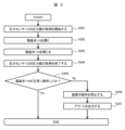
- FIG. 4 is a flowchart showing a procedure for detecting normal operation of a solenoid valve
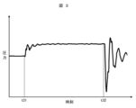
- FIG. 3 is a diagram showing an example of pressure values acquired in the processes from S201 to S204 in FIG. 2
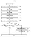
- 4 is a flowchart showing a procedure for detecting normal operation of a solenoid valve
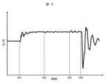
- FIG. 5 is a diagram showing an example of pressure values acquired in the processes from S401 to S406 in FIG.
- the automatic analyzer can detect whether or not the plurality of fluid control valves provided in the automatic analyzer operate normally by using the detection elements that are pre-installed in the automatic analyzer.
- the pre-installed detection elements are, for example, a pressure sensor that measures the pressure in the flow path, and a liquid level detection element that detects the position of the liquid level of the liquid.
- a sensing element since it is not necessary to additionally attach a sensing element to check the operation of the fluid control valve, it is possible to detect whether the fluid control valve is operating normally or not at low cost.
- an automatic analyzer includes a dispensing unit that aspirates a specified amount of specimen and reagent and discharges it into a reaction container, and a detection unit that analyzes a mixed solution (reaction liquid) of the specimen and reagent.
- a dispensing unit that aspirates a specified amount of specimen and reagent and discharges it into a reaction container
- a detection unit that analyzes a mixed solution (reaction liquid) of the specimen and reagent.
- the configuration provided will be described.
- the fluid control valve is assumed to be a solenoid valve.
- FIG. 1 is a schematic configuration diagram of an automatic analyzer according to Example 1 of the present invention.
- the automatic analyzer according to the present embodiment includes a dispensing unit 101, a detection unit 103, a control unit 100, a channel for feeding liquid, and a plurality of solenoid valves (fluid control valves) installed in the channel. valve).
- the control unit 100 controls the entire automatic analyzer.
- a fluid control valve switches between opening and closing the flow path.
- the dispensing unit 101 includes a dispensing nozzle 101a and a dispensing arm 101b, and uses the dispensing nozzle 101a to aspirate a specified amount of sample and reagent.
- the sample and reagent aspirated by the dispensing unit 101 are discharged into the reaction container 102 and mixed.
- this mixed solution of specimen and reagent is referred to as a reaction liquid.
- the reaction container 102 containing the reaction solution is conveyed to the detection unit 103 after the temperature is adjusted for a certain period of time.
- the detection unit 103 includes a reaction liquid suction nozzle 103a, a detection element 103b, and a liquid level detection element 103c, and sucks the reaction liquid in the reaction container 102 using the reaction liquid suction nozzle 103a. The sucked reaction liquid is sent into the detection element 103b.
- the detection unit 103 analyzes the reaction liquid with the detection element 103b, and detects, for example, the absorbance and the amount of luminescence as the analysis result of the reaction liquid.
- the detection element 103b detects the characteristics of the reaction liquid and quantifies the amount of a predetermined component in the reaction liquid (for example, the concentration of the predetermined component contained in the reaction liquid).
- Specific configuration examples of the detection element 103b include a combination of a light source and a photometer, and a combination of an electrode and a photodetection element.
- a detection element 103b equipped with a light source and a photometer detects absorbance as a characteristic of the reaction solution.
- a detection element 103b including an electrode and a photodetection element detects the amount of light emitted as a characteristic of the reaction solution.
- the liquid surface detection element 103c can detect the position of the liquid surface of the liquid, and detects that the reaction liquid suction nozzle 103a is immersed in liquid such as the reaction liquid and that it is separated from the liquid.
- the automatic analyzer has a tank 104 containing a cleaning liquid for cleaning.
- the cleaning liquid contained in the tank 104 is pure water, a solution containing a surfactant, or the like, and is used for cleaning to prevent liquid remaining in the dispensing unit 101 or detection unit 103 from being carried over to the next analysis.
- the flow path from tank 104 is connected to branch block 107 .
- Cleaning liquid contained in tank 104 is pumped to branch block 107 using pump 106 .
- Electromagnetic valves 108, 110, 113, and 115 control the start and stop of feeding the cleaning liquid to the respective channels.
- a channel branching from the branch block 107 to the electromagnetic valve 108 is connected to the dispensing nozzle cleaning tank 109 .
- the dispensing nozzle cleaning tank 109 cleans the dispensing nozzle 101a by discharging the cleaning liquid sent from the tank 104 .
- This washing liquid is discharged from the pipetting nozzle washing tank 109 onto the outer wall of the pipetting nozzle 101a to wash away the specimen or reagent components, thereby preventing the specimen or reagent components from being carried over to the next analysis.
- the solenoid valve 108 switches between opening and closing of the flow path connecting the dispensing nozzle cleaning tank 109 and the branch block 107 to control the start and stop of feeding the cleaning liquid to this flow path.
- a channel branching from the branch block 107 to the electromagnetic valve 110 is connected to the dispensing nozzle 101a.
- a pipetting syringe 111 and a pressure sensor 112 are connected to this channel between the electromagnetic valve 110 and the pipetting nozzle 101a.
- the dispensing syringe 111 serves to aspirate and discharge a specified amount of sample and reagent.
- the pressure sensor 112 has a role of measuring the pressure in the channel and checking whether the channel is clogged and whether there are any abnormalities in the suction and discharge of the specimen and the reagent. Examples of abnormalities in the aspiration and ejection of the sample and reagent include high viscosity of the sample, clogging of the flow path due to fibrin in the sample, and suction of air bubbles on the surface of the liquid.
- the responsiveness of the dispensing syringe 111 to the suction/discharge operation can be enhanced.
- the inner wall of the dispensing nozzle 101a can be cleaned by discharging the cleaning liquid from the tip of the dispensing nozzle 101a.
- a flow path branching from the branch block 107 to the solenoid valve 113 is connected to the detection element 103b.
- a detection syringe 114 is connected to this flow path connecting the electromagnetic valve 113 and the detection element 103b.
- the detection syringe 114 is installed between the electromagnetic valve 113 and the detection element 103b, sucks the reaction liquid and the reagent (detection reagent) used for analyzing the reaction liquid, and sends the liquid to the detection element 103b of the detection unit 103. have a role.
- a flow path branching from the branch block 107 to the solenoid valve 115 is connected to the branch block 116 .
- the automatic analyzer includes a detection reagent bottle 117 containing a detection reagent. A flow path from the detection reagent bottle 117 is connected to the branch block 116 .
- a solenoid valve 118 is installed in the channel connecting the detection reagent bottle 117 and the branch block 116 .
- the solenoid valve 118 switches between opening and closing of the flow path connecting the detection reagent bottle 117 and the branch block 116 to control the start and stop of liquid transfer to this flow path.
- a pump 119 is installed on the downstream side of the branch block 116 .
- a discharge nozzle 120 is installed downstream of the pump 119 .
- the discharge nozzle 120 is connected to the solenoid valve 115 and the solenoid valve 118 by a flow path.
- the cleaning liquid in the tank 104 or the detection reagent in the detection reagent bottle 117 is sent to the pump 119 .
- dispensing nozzle 120 can dispense wash fluid or detection reagent into reagent cup 121 .
- the reagent cup 121 is a container in which the liquid level detection element 103c can detect the position of the liquid level.
- the cleaning liquid is used for cleaning the reagent cup 121 and cleaning the detection element 103b.
- the detection reagent is used for conditioning the surface of the detection element 103b and washing the detection element 103b.
- the detection syringe 114 sucks the reaction liquid from the reaction container 102 with the reaction liquid suction nozzle 103a, and sends the sucked reaction liquid to the detection element 103b. Further, the detection syringe 114 sucks the washing liquid or the detection reagent discharged into the reagent cup 121 from the discharge nozzle 120 from the reagent cup 121 with the reaction liquid suction nozzle 103a, and sends the suctioned detection reagent to the detection element 103b. liquid.
- the automatic analyzer has a tank 105 containing a cleaning liquid for cleaning.
- the cleaning liquid contained in tank 105 is the same liquid as the cleaning liquid contained in tank 104 .
- a flow path from the tank 105 is connected to the discharge nozzle 124 .
- a pump 122 and an electromagnetic valve 123 are installed in a flow path connecting the tank 105 and the discharge nozzle 124 . That is, the electromagnetic valve 123 is connected to the discharge nozzle 124 by a flow path.
- the cleaning liquid contained in tank 105 is sent to discharge nozzle 124 via electromagnetic valve 123 using pump 122 .
- the ejection nozzle 124 ejects the cleaning liquid into the cleaning tank 125 .
- the discharge nozzle 124 discharges the cleaning liquid to the reaction liquid suction nozzle 103a inserted in the washing tank 125, so that the reaction liquid adhering to the outer wall of the reaction liquid suction nozzle 103a can be washed away.
- the automatic analyzer includes solenoid valve 110, solenoid valve 108, solenoid valve 118, solenoid valve 115, solenoid valve 123, and solenoid valve 110, solenoid valve 108, solenoid valve 118, and solenoid valve 123 as fluid control valves for switching between opening and closing of the flow path.
- a solenoid valve 113 is provided. Electromagnetic valve 110 , electromagnetic valve 108 , electromagnetic valve 118 , electromagnetic valve 115 , and electromagnetic valve 113 are connected to pressure sensor 112 through flow paths.
- the solenoid valve 118 and the solenoid valve 115 are connected to the discharge nozzle 120 by a channel.
- the solenoid valve 123 is connected to the discharge nozzle 124 through a flow path.
- FIG. 2 is a flow chart showing the procedure for detecting that the solenoid valve 110 has operated normally.
- the solenoid valve 110 is installed in a flow path connecting the branch block 107 and the dispensing nozzle 101a.
- a pressure sensor 112 is installed between the solenoid valve 110 and the dispensing nozzle 101a in the channel connecting the solenoid valve 110 and the dispensing nozzle 101a. That is, a pressure sensor 112 is installed in the flow path where the electromagnetic valve 110 is installed. Therefore, based on the pressure value measured by the pressure sensor 112, the control unit 100 can detect whether or not the solenoid valve 110 operates normally.
- the solenoid valve 110 is opened.
- the cleaning liquid starts to be sent to the channel.
- S206 and S207 are processes when the solenoid valve 110 does not operate normally.
- the operation of the automatic analyzer is stopped.
- an alert is output to notify that the solenoid valve 110 is not operating normally.
- FIG. 3 is a diagram showing an example of pressure values acquired in the processes from S201 to S204 in FIG.
- time t31 is the time when the solenoid valve 110 is opened
- time t32 is the time when the solenoid valve 110 is closed.
- the water hammer immediately after time t32 does not occur unless both the opening and closing operations of the solenoid valve 110 are successful. Therefore, when the amplitude of the pressure change caused by the water hammer immediately after time t32 is equal to or greater than a predetermined constant value, it can be determined that the solenoid valve 110 has normally operated.
- the solenoid valve 110 when the pressure between time t31 and time t32 is higher than the pressure before time t31 and the pressure after time t32, it can be determined that the solenoid valve 110 has operated normally. In addition, it is possible to determine whether or not the solenoid valve 110 operates normally based only on the pressure value when the solenoid valve 110 is closed, or to determine whether the solenoid valve 110 operates normally based only on the pressure value after the solenoid valve 110 is closed. It is also possible to judge whether or not
- the control unit 100 acquires pressure values from before the electromagnetic valve 110 is opened to after it is closed. If it is possible to determine whether or not the solenoid valve 110 operates normally based only on the pressure value (change in pressure value) when the solenoid valve 110 is closed (S203), the procedures of S201 and S202 can be interchanged. That is, the control unit 100 can start acquiring the pressure value measured by the pressure sensor 112 after opening the solenoid valve 110 and before closing the solenoid valve 110 (between S202 and S203).
- S201 can be a procedure after S203. That is, the control unit 100 can start acquiring the pressure value measured by the pressure sensor 112 after closing the solenoid valve 110 .
- the control unit 100 executes a process of stopping the operation of the automatic analyzer (S206). It is desirable to determine the contents of the processing in S206 in consideration of the risk when the solenoid valve 110 fails.
- the dispensing nozzle 101a is moved to the dispensing nozzle cleaning tank 109. It is desirable to stop the operation of the automatic analyzer after reducing the risk of water leakage. At this time, it is desirable to stop the operation of the pump 106 as early as possible. In addition, if it is considered that the dispensing operation related to analysis cannot be performed normally even though there is no serious effect such as water leakage, in S206, the subsequent dispensing operation is canceled and only the previously dispensed sample is analyzed. It is also possible to continue with
- the flow path in which the solenoid valve 108 is installed is a flow path whose flow rate is greater than a predetermined value when the solenoid valve 108 is opened.
- the flow path in which the electromagnetic valve 108 is installed (the flow path connecting the dispensing nozzle cleaning tank 109 and the branch block 107) is replaced by the flow path in which the electromagnetic valve 115 is installed (the branch block 107 and the branch block 107). and the flow path connecting the branch block 116) and the flow path in which the electromagnetic valve 113 is installed (the flow path connecting the branch block 107 and the detection syringe 114).
- the flow rate is large when the electromagnetic valves 108, 115, 113, which are connected to the air, are opened.
- the flow path in which the solenoid valve 108 is installed matches the flow rate of the flow path in which the pressure sensor 112 is installed (the flow path in which the branch block 107 and the dispensing nozzle 101a are connected and the solenoid valve 110 is installed). It is a channel with a large flow rate to the extent that it has an effect.
- the change in pressure when the solenoid valve 108 is opened is large, and the pressure sensor 112 can easily measure the change in pressure due to the opening of the solenoid valve 108 . Therefore, the control unit 100 detects whether or not the solenoid valve 108 operates normally based on the pressure value measured by the pressure sensor 112 by opening and closing the solenoid valve 108 with the solenoid valve 110 open. be able to.
- FIG. 4 is a flow chart showing the procedure for detecting that the solenoid valve 108 has operated normally.
- the solenoid valve 108 is opened. Due to the opening of the solenoid valve 108, the flow rate of the flow path in which the pressure sensor 112 is installed (the flow path in which the solenoid valve 110 is installed) greatly changes.
- the electromagnetic valve 108 is closed.
- S408 and S409 are processes when the solenoid valve 108 does not operate normally. At S408, subsequent analysis operations of the automatic analyzer are stopped. At S409, an alert is output to notify that the solenoid valve 108 is not operating normally.
- FIG. 5 is a diagram showing an example of pressure values acquired in the processes from S401 to S406 in FIG.
- time t51 is the time when the solenoid valve 110 is opened
- time t52 is the time when the solenoid valve 108 is opened
- time t53 is the time when the solenoid valve 108 is closed
- time t54 is This is the time when the solenoid valve 110 is closed.
- the electromagnetic valve 108 is opened and closed. Both operations were successful, and it can be determined that the solenoid valve 108 operated normally.
- the control unit 100 acquires pressure values from before the electromagnetic valve 110 is opened to after it is closed. If it is possible to determine whether or not the solenoid valve 108 operates normally based only on the pressure value (change in pressure value) when the solenoid valve 108 is closed (S404), S401 can be a procedure after S403. can. That is, the control unit 100 can start acquiring the pressure value measured by the pressure sensor 112 after opening the solenoid valve 108 and before closing the solenoid valve 108 (between S403 and S404).
- S401 can be a procedure after S404. That is, the control unit 100 can start acquiring the pressure value measured by the pressure sensor 112 after closing the solenoid valve 108 .
- the control unit 100 executes a process of stopping subsequent dispensing operations of the automatic analyzer (S408). It is desirable that the contents of the processing in S408 be determined in consideration of the risk when the solenoid valve 108 fails. For example, if the failure of the solenoid valve 108 is considered to have a serious effect on the automatic analyzer due to water leakage or the like, it is desirable to stop the operation of the automatic analyzer immediately in S408.
- the solenoid valve 118 is installed in the flow path connecting the detection reagent bottle 117 and the branch block 116 .
- a pump 119 is installed in the flow path on the downstream side of the branch block 116, and a discharge nozzle 120 is connected.
- the solenoid valve 118 cannot detect whether it has operated normally based on the pressure value measured by the pressure sensor 112. Whether or not the solenoid valve 118 has operated normally is determined by opening and closing the solenoid valve 118 to eject the detection reagent from the detection reagent bottle 117 into the reagent cup 121 from the ejection nozzle 120, and the ejected detection reagent. can be detected based on the volume of Since the dimensions of the reagent cup 121 are known, the volume of the detection reagent discharged into the reagent cup 121 can be obtained by detecting the position of the liquid surface of the detection reagent with the liquid level detection element 103c. That is, whether or not the electromagnetic valve 118 has operated normally can be detected by detecting the position of the liquid surface of the detection reagent discharged into the reagent cup 121 by opening and closing the electromagnetic valve 118 .
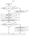
- FIG. 6 is a flow chart showing the procedure for detecting that the solenoid valve 118 has operated normally.
- the reagent cup 121 is empty. Whether or not the reagent cup 121 is empty can be checked using, for example, the liquid level detection element 103c. If the liquid level detection element 103c detects the liquid level in the reagent cup 121, it can be determined that the reagent cup 121 is not empty, and the process of S602 is performed. If the liquid level detection element 103c does not detect the liquid level in the reagent cup 121, it can be determined that the reagent cup 121 is empty, and the process of S603 is performed.
- the reagent cup 121 is emptied.
- the reagent cup 121 can be emptied by the detection syringe 114 sucking the liquid in the reagent cup 121 with the reaction liquid suction nozzle 103a.
- the solenoid valve 118 is opened.
- the detection reagent in the detection reagent bottle 117 is discharged from the discharge nozzle 120 into the reagent cup 121 .
- the solenoid valve 118 is closed.
- the detection reagent is discharged into the reagent cup 121 by a predetermined constant volume.
- S607 and S608 are processes when the solenoid valve 118 does not operate normally. In S607, subsequent analysis operations of the automatic analyzer are stopped. At S608, an alert is output to notify that the solenoid valve 118 is not operating normally.
- the solenoid valve 118 When the solenoid valve 118 does not operate normally and the solenoid valve 118 does not open, the liquid level of the liquid in the reagent cup 121 is lower than when the solenoid valve 118 operates normally. Therefore, when the position of the liquid level detected in the process of S605 is lower than the predetermined position (and when the liquid level detection element 103c does not detect the liquid level in the reagent cup 121 in the process of S605), A criterion can be used to determine that the solenoid valve 118 has not operated normally.
- the solenoid valve 118 does not operate normally and the solenoid valve 118 does not close, the liquid level of the liquid in the reagent cup 121 is higher than the position when the solenoid valve 118 operates normally. . Therefore, it is possible to use a judgment criterion that it is judged that the solenoid valve 118 did not operate normally when the position of the liquid surface detected in the process of S605 is higher than a predetermined position.
- the electromagnetic valve 118 is judged to operate normally. can be used.
- the processes of S601 and S602 are processes performed in order to correctly measure the volume of the detection reagent discharged into the reagent cup 121 by opening the solenoid valve 118 in S603. Even if the reagent cup 121 is not emptied in the process of S602, if the volume of the liquid present in the reagent cup 121 is known before the process of S603, the amount of liquid ejected into the reagent cup 121 can be detected in the subsequent steps. Reagent volume can be measured correctly.
- the solenoid valve 115 is installed in a flow path connecting the branch block 107 and the branch block 116 .
- a pump 119 is installed in the flow path on the downstream side of the branch block 116, and a discharge nozzle 120 is connected.
- the flow path in which the solenoid valve 115 is installed has a smaller flow rate than the flow path in which the solenoid valve 108 is installed when the solenoid valves 115 and 108 installed in the respective flow paths are opened. is the road. Therefore, it is detected whether or not the solenoid valve 115 has operated normally based on the pressure value measured by the pressure sensor 112, as in the procedure (FIG. 4) for detecting that the solenoid valve 108 has operated normally. I can't.
- the electromagnetic valve 115 operates normally depends on whether or not the electromagnetic valve 115 is opened and closed to discharge the washing liquid from the tank 104 into the reagent cup 121 from the discharge nozzle 120 and to It can be detected by detecting the position (volume) of the liquid level of the cleaning liquid with the liquid level detection element 103c.
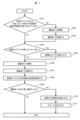
- FIG. 7 is a flow chart showing the procedure for detecting that the solenoid valve 115 has operated normally.
- the liquid level detection element 103c can detect the liquid level of the detection reagent in the detection reagent bottle 117, but the liquid level of the cleaning liquid in the tank 104 can be detected. is difficult to detect, the flow chart of the procedure for detecting that the solenoid valve 115 has operated normally is shown.
- the liquid level detection element 103c is composed of an element that detects the liquid level based on changes in capacitance.
- the ease of detecting the liquid surface may vary depending on the difference in physical property values such as relative permittivity and conductivity of the liquid.
- the flow chart of FIG. 7 shows a procedure for detecting that the electromagnetic valve 115 has normally operated using the liquid level detection element 103c, which is difficult to detect the level of the cleaning liquid in the tank 104.
- the control unit 100 determines whether or not the flow path from the branch block 116 to the discharge nozzle 120 is filled with the detection reagent based on the history of the operation of the automatic analyzer. For example, after the electromagnetic valve 118 is opened and the detection reagent is discharged from the discharge nozzle 120, if nothing is discharged from the discharge nozzle 120, the flow path from the branch block 116 to the discharge nozzle 120 is filled with the detection reagent. It is determined that
- the solenoid valve 118 is opened.
- the detection reagent in the detection reagent bottle 117 is discharged from the discharge nozzle 120 .
- the solenoid valve 118 is closed.
- the flow path from the branch block 116 to the ejection nozzle 120 is filled with the detection reagent.
- the reagent cup 121 is emptied.
- the processing of S705 can be performed in the same manner as the processing of S602 in FIG.
- the solenoid valve 115 is opened.
- the cleaning liquid in the tank 104 is discharged from the discharge nozzle 120 into the reagent cup 121 .
- the solenoid valve 115 is closed.
- the washing liquid in the tank 104 is discharged into the reagent cup 121 by a predetermined constant volume. Since the flow path from the branch block 116 to the ejection nozzle 120 is filled with the detection reagent by the processing from S701 to S703, the cleaning liquid in the tank 104 and the detection reagent in the detection reagent bottle 117 are stored in the reagent cup 121. Reagents are mixed.
- the liquid surface position of the liquid in the reagent cup 121 is detected by the liquid surface detection element 103c. It is difficult for the liquid level detection element 103 c to detect the liquid level of the cleaning liquid in the tank 104 . However, since the liquid surface detection element 103c detects the position of the liquid surface of the mixture of the cleaning liquid and the detection reagent in the processing of S708, the position of the liquid surface of the liquid in the reagent cup 121 can be detected.
- S710 and S711 are processes when the solenoid valve 115 does not operate normally. At S710, subsequent analysis operations of the automatic analyzer are stopped. At S711, an alert is output to notify that the solenoid valve 115 is not operating normally.
- the criteria for determining whether or not the solenoid valve 115 has operated normally in S709 can be the same as those used in the process of S606 in FIG. That is, the control unit 100 can determine that the solenoid valve 115 did not operate normally when the position of the liquid surface detected in the process of S708 is lower than the predetermined position. Alternatively, the control unit 100 can determine that the solenoid valve 115 did not operate normally when the position of the liquid surface detected in the process of S708 is higher than the predetermined position. Alternatively, the control unit 100 can determine that the solenoid valve 115 has normally operated when the position of the liquid level detected in the process of S708 is within a predetermined range.
- the predetermined position and the predetermined range of the liquid surface used for the above judgment criteria are discharged from the branch block 116. It is necessary to consider the volume of the detection reagent that fills the flow path up to the nozzle 120 and determine it.
- the volume of this detection reagent can be obtained in advance from the specifications of the automatic analyzer, such as the volume of this channel.
- the solenoid valve 123 Since the flow path in which the solenoid valve 123 is installed is not connected to the flow path in which the pressure sensor 112 is installed, whether or not the solenoid valve 123 operates normally is determined based on the pressure value measured by the pressure sensor 112. or cannot be detected. However, whether or not the solenoid valve 123 operates normally depends on whether or not the solenoid valve 123 is opened and closed to discharge the washing liquid in the tank 105 into the reagent cup 121 through the discharge nozzle 124, similarly to the solenoid valves 118 and 115. , and the position (volume) of the liquid surface of the discharged cleaning liquid can be detected by the liquid surface detection element 103c.
- FIG. 8 is a flow chart showing the procedure for detecting that the solenoid valve 123 has operated normally. As an example in FIG. 8, similar to FIG. A flow chart of the procedure for detecting that the electromagnetic valve 123 is operating normally is shown for the case where the liquid level can be detected but the liquid level of the cleaning liquid in the tank 105 is difficult to detect.
- the reagent cup 121 is emptied.
- the processing of S802 can be performed in the same manner as the processing of S602 in FIG.
- the solenoid valve 118 is opened.
- the detection reagent in the detection reagent bottle 117 is discharged from the discharge nozzle 120 into the reagent cup 121 .
- the solenoid valve 118 is closed.
- the reagent cup 121 is in a state in which a predetermined volume of the detection reagent is contained.
- the electromagnetic valve 123 is opened.
- the cleaning liquid in the tank 105 is discharged from the discharge nozzle 124 into the reagent cup 121 .
- the solenoid valve 123 is closed.
- the washing liquid in the tank 105 is discharged into the reagent cup 121 by a predetermined volume.
- the washing liquid in the tank 105 and the detection reagent in the detection reagent bottle 117 are mixed in the reagent cup 121 by the processes from S803 to S804 and from S806 to S807.
- the liquid surface position of the liquid in the reagent cup 121 is again detected by the liquid surface detection element 103c. It is difficult for the liquid level detection element 103 c to detect the liquid level of the cleaning liquid in the tank 105 . However, since the liquid surface detection element 103c detects the position of the liquid surface of the mixture of the cleaning liquid and the detection reagent in the process of S808, the position of the liquid surface of the liquid in the reagent cup 121 can be detected.
- S810 and S811 are processes when the solenoid valve 123 does not operate normally.
- subsequent analysis operations of the automatic analyzer are stopped.
- an alert is output to notify that the solenoid valve 123 is not operating normally.
- the difference between the positions of the liquid levels detected in the processes of S805 and S808 is within a predetermined range.
- the volume of the cleaning liquid in the tank 105 discharged into the reagent cup 121 can be obtained from the difference in the position of the liquid surface detected in the process of S805 and the process of S808. Therefore, if there is sufficient free space in the reagent cup 121 and the liquid (mixed liquid) does not overflow from the reagent cup 121 even if the cleaning liquid in the tank 105 is discharged into the reagent cup 121 in S806, S801 and S801 are performed. The processing of S802 can be omitted.
- Solenoid valve 113 Next, the configuration for detecting that the solenoid valve 113 is operating normally in the automatic analyzer according to this embodiment will be described. As shown in FIG. 1 , the solenoid valve 113 is installed in a flow path connecting the branch block 107 and the detection unit 103 . A detection syringe 114 is installed between the solenoid valve 113 and the detection unit 103 .
- the flow path in which the solenoid valve 113 is installed has a smaller flow rate than the flow path in which the solenoid valve 108 is installed when the solenoid valves 113 and 108 installed in the respective flow paths are opened. is the road. Therefore, it is detected whether or not the solenoid valve 113 is operating normally based on the pressure value measured by the pressure sensor 112, as in the procedure (FIG. 4) for detecting that the solenoid valve 108 is operating normally. I can't. However, since the flow path in which the solenoid valve 113 is installed is connected to the detection unit 103, whether or not the solenoid valve 113 has operated normally is determined based on the detection result of the reaction liquid in the detection unit 103. detectable.
- FIG. 9 is a flow chart showing the procedure for detecting that the solenoid valve 113 has operated normally.
- the electromagnetic valve 113 is opened. As a result, the cleaning liquid in the tank 104 is sent to clean the inside of the channel.
- the solenoid valve 113 is closed. After the electromagnetic valve 113 is closed, the detection syringe 114 sucks the reaction liquid from the reaction container 102 with the reaction liquid suction nozzle 103 a and feeds the sucked reaction liquid to the detection unit 103 .
- the detection unit 103 detects the reaction solution.
- the detection unit 103 can detect this reaction liquid.
- the detection unit 103 determines that the electromagnetic valve 113 has normally operated when the reaction liquid sent from the detection syringe 114 can be detected and analyzed. If the solenoid valve 113 operates normally, the process of the flowchart of FIG. 9 ends.
- S905 and S906 are processes when the solenoid valve 113 does not operate normally.
- the subsequent dispensing operation of the automatic analyzer is stopped.
- an alert is output to notify that the solenoid valve 113 is not operating normally.
- the control unit 100 determines whether or not the solenoid valve 113 has operated normally based on the result of detection of the reaction liquid by the detection unit 103 in S903. For example, if the measured value (for example, absorbance or luminescence amount) obtained by measuring the reaction liquid by the detection unit 103 in S903 is within a predetermined range, it is determined that the solenoid valve 113 has normally operated. can be used. Alternatively, it is possible to use a criterion that it is determined that the solenoid valve 113 did not operate normally when the measured value is equal to or less than a predetermined value. Alternatively, it is possible to use a criterion that it is determined that the solenoid valve 113 did not operate normally when the measured value is equal to or greater than a predetermined value.
- the measured value for example, absorbance or luminescence amount
- the solenoid valve 110 As described above, in the automatic analyzer according to this embodiment, different procedures are used for the solenoid valve 110, the solenoid valve 108, the solenoid valve 118, the solenoid valve 115, the solenoid valve 123, and the solenoid valve 113, Determine whether these solenoid valves operate normally.
- the information to be used for determining whether the operation of the solenoid valve is normal is different for each solenoid valve. An example of a method for determining which information should be used to determine whether or not the operation of a solenoid valve is normal will be described below.
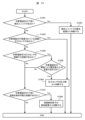
- FIG. 10 is a flow chart showing an example of a method for determining which information should be used to determine whether the solenoid valve has operated normally.
- the procedure of the flowchart shown in FIG. 10 is executed by the designer who designs the automatic analyzer. The designer uses the flow chart shown in FIG. 10 to determine which information should be used to determine whether or not the operation of the solenoid valve is normal.
- a solenoid valve for which it is desired to determine whether or not the operation is normal will be referred to as a "target solenoid valve".
- the solenoid valve 113 is the only solenoid valve to which the detection unit 103 is connected downstream. That is, when the target solenoid valve is the solenoid valve 113, the designer decides to make a judgment based on the detection result of the reaction liquid by the detection unit 103 (FIG. 9).
- the detection unit 103 For solenoid valves to which the detection unit 103 is connected downstream, it is often possible to determine whether or not the operation is normal based on the detection result of the reaction liquid by the detection unit 103 . In addition, since the processing of detecting by the detection unit 103 after opening and closing the target electromagnetic valve (processing corresponding to S901 to S903 in FIG. 9) is often included in the normal analysis operation, the detection unit 103 It is possible to determine whether the solenoid valve to which is connected operates normally within the normal analysis operation.
- the target solenoid valve 110 is a solenoid valve in which a pressure sensor 112 is installed in the flow path where the solenoid valve 110 is installed. That is, when the target solenoid valve is the solenoid valve 110, the designer decides to make a judgment based on the pressure value measured by the pressure sensor 112 (FIG. 2).
- solenoid valve 108 is a solenoid valve through which the liquid flows at a flow rate equal to or greater than the specified amount when the solenoid valve 108 is opened. That is, when the target solenoid valve is the solenoid valve 108, the designer decides to make a judgment based on the pressure value measured by the pressure sensor 112 (FIG. 4).
- the target solenoid valve (solenoid valve 110) in which the pressure sensor 112 is installed in the installed flow path, and in S1006, the target solenoid in which the flow rate of the specified amount or more of liquid flows when opened In many cases, it is possible to determine whether the valve (solenoid valve 108) is operating normally from the pressure value measured by the pressure sensor 112 . Decisions using pressure sensor 112 measurements can be made in as little as one second or less. For this reason, considering the time efficiency, it is desirable to use the measured value of the pressure sensor 112 to determine whether or not the solenoid valve operates normally using the measured value of the pressure sensor 112 .
- the discharge nozzles 120 and 124 are installed downstream of the target electromagnetic valve, and it is checked whether or not a container (reagent cup 121) capable of detecting the liquid surface is arranged. If a container whose liquid level can be detected is arranged downstream of the target electromagnetic valve, the procedure of S1008 is executed.
- the target solenoid valve it is determined whether or not the target solenoid valve has operated normally based on the detection result of the liquid level detection element 103c.
- the liquid level detection element 103 c detects the position of the liquid level of the liquid discharged from the discharge nozzles 120 and 124 to the reagent cup 121 .
- the solenoid valves 115, 118, and 123 are solenoid valves downstream of which the discharge nozzles 120 and 124 are installed and the reagent cup 121 is arranged.
- the designer should check the detection result of the liquid level detection element 103c (the position of the liquid level of the liquid discharged into the reagent cup 121). ) (FIGS. 7, 6, 8).
- the discharge nozzles 120 and 124 are installed downstream, and the electromagnetic valve in which the reagent cup 121 is arranged can often be determined whether it has operated normally from the detection result of the liquid level detection element 103c.
- the flowchart shown in FIG. 10 shows an example of a method of determining which information is used to determine whether the solenoid valve has operated normally.
- the information used to determine whether the solenoid valve has operated normally is not limited to that determined by the flow chart shown in FIG.
- the automated analyzer is equipped with other sensing elements such as vibration sensors or cameras, such sensing elements can also be utilized.
- it is considered that there is an adverse effect such as a throughput loss when trying to make a determination with a certain sensing element it is desirable to utilize another sensing element.
- the procedure for determining whether the solenoid valve has operated normally differs depending on the solenoid valve. It is desirable to decide when to perform each procedure by taking into consideration both the time required for the procedure to be determined and the risk of failure of the solenoid valve. Below, an example of a method for determining the timing of performing the procedure for determining whether or not the solenoid valve has operated normally will be described.
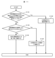
- FIG. 11 is a flow chart showing an example of a method for determining the timing of performing the procedure for determining whether the solenoid valve has operated normally.
- the procedure of the flowchart shown in FIG. 11 is executed by the designer who designs the automatic analyzer. The designer uses the flowchart shown in FIG. 11 to determine at what timing it should be determined whether or not the target solenoid valve operates normally.
- the above-mentioned mechanism operation refers to the operation of spatially moving some of the components of the automatic analyzer, such as the rotation of the motor and the opening and closing of the solenoid valve. opening/closing operation, liquid surface detection operation, and reaction liquid detection operation.
- the solenoid valves 110 and 113 are included in the analysis procedure of the automatic analyzer for determining whether or not they operate normally.
- the procedure of S1102 is a procedure that does not need to be added to normal analysis operations. Specifically, in this embodiment, since the processing from S201 to S204 in FIG. 2 and the processing from S901 to S903 in FIG. 9 are included in the normal analysis operation, A procedure that does not require additional mechanical action to determine whether or not the Therefore, in these procedures, it is possible to determine whether the target solenoid valve operates normally without spending time on other than the normal analysis operation.
- solenoid valves for which failure does not pose a significant risk are solenoid valve 108 , solenoid valve 115 , solenoid valve 118 and solenoid valve 123 .
- the automatic analyzer according to this embodiment can detect whether or not all of the plurality of solenoid valves provided are operating normally at low cost without installing additional detection elements. Therefore, the reliability of the automatic analyzer according to this embodiment can be improved.
- Example 2 of the present invention An automatic analyzer according to Example 2 of the present invention will be described.
- the description of the configuration common to the automatic analyzer according to the first embodiment will be omitted.
- the configuration for detecting whether or not the plurality of solenoid valves provided in the automatic analyzer operate normally has been described.
- detecting whether the operation of the solenoid valve is normal it is also possible to detect whether the pressure of the pump is normal.
- FIG. 12 is a flow chart showing the procedure for detecting that the solenoid valve 123 is operating normally and that the pressure of the pump 122 is normal in the automatic analyzer according to this embodiment. Note that the processing of the flowchart shown in FIG. 12 is executed by the control unit 100 unless otherwise specified.
- the processing from S1201 to S1208 is the same as the processing from S801 to S808 in FIG.
- the process of determining whether or not the electromagnetic valve 123 has operated normally in S1209 is the same as the process of S809 in FIG.
- the processing of S1211 and S1212 is the same as the processing of S810 and S811 in FIG.
- An example of criteria used when the control unit 100 determines whether the pressure of the pump 122 is normal in S1210 is shown below.
- the pressure of the pump 122 is normal, the amount of cleaning liquid discharged in the processing from S1206 to S1207 in FIG. 12 falls within a predetermined range.
- the pressure of the pump 122 decreases, the amount of cleaning liquid discharged decreases, and when the pressure of the pump 122 increases, the amount of cleaning liquid discharged increases. For this reason, it is possible to use a judgment criterion that it is judged that the pressure of the pump 122 is normal when the difference between the positions of the liquid levels detected by the processing of S1205 and the processing of S1208 is within a predetermined range. can be done.
- the pressure of the pump 122 is normal if the difference between the positions of the liquid levels is equal to or greater than a predetermined value. can be used.
- the pressure of the pump 122 is normal if the difference between the positions of the liquid levels is equal to or less than a predetermined value. can be used.
- the automatic analyzer can detect whether the solenoid valve is operating normally and whether the pressure of the pump is normal at low cost without installing an additional detection element. can increase
- the present invention is not limited to the above embodiments, and various modifications are possible.
- the above embodiments have been described in detail in order to facilitate understanding of the present invention, and the present invention is not necessarily limited to aspects having all the described configurations.
- part of the configuration of one embodiment can be replaced with the configuration of another embodiment.
- add the configuration of another embodiment to the configuration of one embodiment.
- Solenoid valve 119 ... Pump 120 ... Discharge nozzle 121 ... Reagent cup 122 ... Pump 123... Solenoid valve 124... Discharge nozzle 125... Cleaning tank t31... Time when solenoid valve 110 opens t32... Time when solenoid valve 110 closes t51... Time when solenoid valve 110 opens t52... Solenoid valve 108 is opened, t53 is the time when the solenoid valve 108 is closed, and t54 is the time when the solenoid valve 110 is closed.
Landscapes
- Physics & Mathematics (AREA)
- Health & Medical Sciences (AREA)
- Life Sciences & Earth Sciences (AREA)
- Chemical & Material Sciences (AREA)
- Analytical Chemistry (AREA)
- Biochemistry (AREA)
- General Health & Medical Sciences (AREA)
- General Physics & Mathematics (AREA)
- Immunology (AREA)
- Pathology (AREA)
- Automatic Analysis And Handling Materials Therefor (AREA)
Abstract
Description
初めに、本実施例による自動分析装置において、電磁弁110が正常に動作したことを検出する構成について説明する。
次に、本実施例による自動分析装置において、電磁弁108が正常に動作したことを検出する構成について説明する。図1に示すように、電磁弁108は、分注ノズル洗浄槽109と分岐ブロック107とを接続する流路に設置されている。
次に、本実施例による自動分析装置において、電磁弁118が正常に動作したことを検出する構成について説明する。図1に示すように、電磁弁118は、検出用試薬ボトル117と分岐ブロック116とを接続する流路に設置されている。分岐ブロック116の下流側にある流路には、ポンプ119が設置されており、吐出ノズル120が接続されている。
次に、本実施例による自動分析装置において、電磁弁115が正常に動作したことを検出する構成について説明する。図1に示すように、電磁弁115は、分岐ブロック107と分岐ブロック116とを接続する流路に設置されている。分岐ブロック116の下流側にある流路には、ポンプ119が設置されており、吐出ノズル120が接続されている。
次に、本実施例による自動分析装置において、電磁弁123が正常に動作したことを検出する構成について説明する。図1に示すように、電磁弁123は、洗浄液を収容したタンク105と吐出ノズル124とを接続する流路に設置されている。
次に、本実施例による自動分析装置において、電磁弁113が正常に動作したことを検出する構成について説明する。図1に示すように、電磁弁113は、分岐ブロック107と検出ユニット103とを接続する流路に設置されている。電磁弁113と検出ユニット103との間には、検出用シリンジ114が設置されている。
Claims (7)
- 液体を送液する流路と、
前記流路に設置され、前記流路の開放と遮断を切り替える複数の流体制御弁と、
前記流路内の圧力を測定する圧力センサと、
液体の液面の位置を検知する液面検知素子と、
制御部と、
を備え、
前記流体制御弁のうち1つ以上は、前記圧力センサと前記流路で接続されている第1の流体制御弁であり、
前記流体制御弁のうち1つ以上は、吐出ノズルと前記流路で接続されている第2の流体制御弁であり、
前記液面検知素子は、前記吐出ノズルが吐出した液体の液面の位置を検知し、
前記制御部は、
前記第1の流体制御弁について、前記圧力センサが測定した前記圧力の値に基づいて正常に動作したか否かを検出し、
前記第2の流体制御弁について、前記液面検知素子が検知した前記液面の位置に基づいて正常に動作したか否かを検出する、
ことを特徴とする自動分析装置。 - 前記第1の流体制御弁を2つ以上備え、
前記制御部は、前記第1の流体制御弁のうち、1つの前記流体制御弁を開放した状態で他の1つの前記流体制御弁を開閉させて、前記圧力センサが測定した前記圧力の値を取得し、取得した前記圧力の値に基づいて、前記他の1つの前記流体制御弁が正常に動作したか否かを検出する、
請求項1に記載の自動分析装置。 - 前記第1の流体制御弁のうち前記他の1つの前記流体制御弁が設置されている前記流路は、前記他の1つの前記流体制御弁を開放したときの流量が予め定めた値より大きい、
請求項2に記載の自動分析装置。 - 前記制御部は、前記他の1つの前記流体制御弁を開いて閉じた後の前記圧力の変化の振幅を基に、前記他の1つの前記流体制御弁が正常に動作したか否かを検出する、
請求項2に記載の自動分析装置。 - 前記第2の流体制御弁を2つ以上備え、
前記液面検知素子は、前記第2の流体制御弁のうち1つの前記流体制御弁が開閉した後で前記液面の位置を検知し、この後、前記第2の流体制御弁のうち他の1つの前記流体制御弁が開閉した後で前記液面の位置を検知し、
前記制御部は、前記液面検知素子が検知したこれらの前記液面の位置の差に基づいて、前記他の1つの前記流体制御弁が正常に動作したか否かを検出する、
請求項1に記載の自動分析装置。 - 前記第2の流体制御弁のうち前記1つの前記流体制御弁が開閉して吐出された前記液体と、前記第2の流体制御弁のうち前記他の1つの前記流体制御弁が開閉して吐出された前記液体は、互いに異なる液体であり、
前記液面検知素子は、前記他の1つの前記流体制御弁が開閉した後では、これらの互いに異なる前記液体の混合液の前記液面の位置を検知する、
請求項5に記載の自動分析装置。 - 検体と試薬の混合溶液である反応液を分析する検出ユニットを備え、
前記流体制御弁のうち1つ以上は、前記検出ユニットと前記流路で接続されている第3の流体制御弁であり、
前記検出ユニットと前記第3の流体制御弁とを接続する前記流路には、シリンジが接続されており、
前記シリンジは、前記反応液を吸引して前記検出ユニットに送液し、
前記制御部は、前記検出ユニットによる前記反応液の検出結果に基づいて、前記第3の流体制御弁が正常に動作したか否かを検出する、
請求項1に記載の自動分析装置。
Priority Applications (3)
| Application Number | Priority Date | Filing Date | Title |
|---|---|---|---|
| CN202280075437.4A CN118251596A (zh) | 2021-11-30 | 2022-11-07 | 自动分析装置 |
| EP22901025.1A EP4443165A4 (en) | 2021-11-30 | 2022-11-07 | AUTOMATIC ANALYSIS DEVICE |
| US18/706,851 US20250035662A1 (en) | 2021-11-30 | 2022-11-07 | Automated Analysis Device |
Applications Claiming Priority (2)
| Application Number | Priority Date | Filing Date | Title |
|---|---|---|---|
| JP2021193980A JP7709366B2 (ja) | 2021-11-30 | 2021-11-30 | 自動分析装置 |
| JP2021-193980 | 2021-11-30 |
Publications (1)
| Publication Number | Publication Date |
|---|---|
| WO2023100592A1 true WO2023100592A1 (ja) | 2023-06-08 |
Family
ID=86611954
Family Applications (1)
| Application Number | Title | Priority Date | Filing Date |
|---|---|---|---|
| PCT/JP2022/041323 Ceased WO2023100592A1 (ja) | 2021-11-30 | 2022-11-07 | 自動分析装置 |
Country Status (5)
| Country | Link |
|---|---|
| US (1) | US20250035662A1 (ja) |
| EP (1) | EP4443165A4 (ja) |
| JP (1) | JP7709366B2 (ja) |
| CN (1) | CN118251596A (ja) |
| WO (1) | WO2023100592A1 (ja) |
Families Citing this family (2)
| Publication number | Priority date | Publication date | Assignee | Title |
|---|---|---|---|---|
| WO2025158807A1 (ja) * | 2024-01-23 | 2025-07-31 | 株式会社日立ハイテク | 自動分析装置、および自動分析装置における異常の有無を判定する方法 |
| CN119936426B (zh) * | 2025-04-08 | 2025-10-03 | 深圳市帝迈生物技术有限公司 | 一种样本分析仪及样本分析仪故障的处理方法 |
Citations (5)
| Publication number | Priority date | Publication date | Assignee | Title |
|---|---|---|---|---|
| JP2007315969A (ja) * | 2006-05-26 | 2007-12-06 | Olympus Corp | 自動分析装置および分注機構の分注異常判定方法 |
| WO2010038546A1 (ja) * | 2008-09-30 | 2010-04-08 | 株式会社 日立ハイテクノロジーズ | 自動分析装置 |
| JP2010217147A (ja) * | 2009-03-19 | 2010-09-30 | Jeol Ltd | 生化学自動分析装置用流系内圧力制御システム |
| JP2013181903A (ja) * | 2012-03-02 | 2013-09-12 | Hitachi High-Technologies Corp | 分析装置および分析方法 |
| WO2020066449A1 (ja) * | 2018-09-25 | 2020-04-02 | 株式会社日立ハイテクノロジーズ | 自動分析装置 |
Family Cites Families (3)
| Publication number | Priority date | Publication date | Assignee | Title |
|---|---|---|---|---|
| JP5975772B2 (ja) * | 2012-07-27 | 2016-08-23 | 株式会社日立ハイテクノロジーズ | 自動分析装置 |
| EP2956403B1 (en) * | 2013-02-15 | 2021-03-31 | Siemens Healthcare Diagnostics Inc. | Real-time volume confirmation dispensing method |
| JP6011875B2 (ja) * | 2013-07-08 | 2016-10-19 | Smc株式会社 | アクチュエータの異常検出システム |
-
2021
- 2021-11-30 JP JP2021193980A patent/JP7709366B2/ja active Active
-
2022
- 2022-11-07 EP EP22901025.1A patent/EP4443165A4/en active Pending
- 2022-11-07 CN CN202280075437.4A patent/CN118251596A/zh active Pending
- 2022-11-07 WO PCT/JP2022/041323 patent/WO2023100592A1/ja not_active Ceased
- 2022-11-07 US US18/706,851 patent/US20250035662A1/en active Pending
Patent Citations (5)
| Publication number | Priority date | Publication date | Assignee | Title |
|---|---|---|---|---|
| JP2007315969A (ja) * | 2006-05-26 | 2007-12-06 | Olympus Corp | 自動分析装置および分注機構の分注異常判定方法 |
| WO2010038546A1 (ja) * | 2008-09-30 | 2010-04-08 | 株式会社 日立ハイテクノロジーズ | 自動分析装置 |
| JP2010217147A (ja) * | 2009-03-19 | 2010-09-30 | Jeol Ltd | 生化学自動分析装置用流系内圧力制御システム |
| JP2013181903A (ja) * | 2012-03-02 | 2013-09-12 | Hitachi High-Technologies Corp | 分析装置および分析方法 |
| WO2020066449A1 (ja) * | 2018-09-25 | 2020-04-02 | 株式会社日立ハイテクノロジーズ | 自動分析装置 |
Non-Patent Citations (1)
| Title |
|---|
| See also references of EP4443165A4 * |
Also Published As
| Publication number | Publication date |
|---|---|
| JP2023080562A (ja) | 2023-06-09 |
| JP7709366B2 (ja) | 2025-07-16 |
| US20250035662A1 (en) | 2025-01-30 |
| EP4443165A4 (en) | 2025-11-26 |
| EP4443165A1 (en) | 2024-10-09 |
| CN118251596A (zh) | 2024-06-25 |
Similar Documents
| Publication | Publication Date | Title |
|---|---|---|
| EP3767299B1 (en) | Automatic analyzing apparatus, and method for detecting flow path clogging of the automatic analyzing apparatus | |
| CN102124351B (zh) | 自动分析装置 | |
| WO2023100592A1 (ja) | 自動分析装置 | |
| CN112867924B (zh) | 自动分析装置 | |
| JP7269869B2 (ja) | 自動分析装置及び分注方法 | |
| JP2010071765A (ja) | 分注プローブ洗浄方法および自動分析装置 | |
| CN104487851A (zh) | 自动分析装置 | |
| JP2004271266A (ja) | 分注装置およびそれを用いた自動分析装置 | |
| JP2002519704A (ja) | 吸引および分配システムをモニタするための方法および装置 | |
| JP7660240B2 (ja) | 液体分注装置 | |
| WO2010032507A1 (ja) | 分注装置、自動分析装置および分注不良確認方法 | |
| JP6830412B2 (ja) | 試験キット、試験方法、分注装置 | |
| CN114364989A (zh) | 自动分析装置 | |
| JP5111328B2 (ja) | 自動分析装置 | |
| EP4317982A1 (en) | Automated analysis device | |
| US12332103B2 (en) | Dispensing device, automated analysis device, and dispensing method | |
| JP7167037B2 (ja) | 自動分析装置および検体分注機構の異常検出方法 | |
| JP3120180U (ja) | 自動分析装置 | |
| JP2000346854A (ja) | 液面検出装置 | |
| CN120712481A (zh) | 自动分析装置 |
Legal Events
| Date | Code | Title | Description |
|---|---|---|---|
| 121 | Ep: the epo has been informed by wipo that ep was designated in this application |
Ref document number: 22901025 Country of ref document: EP Kind code of ref document: A1 |
|
| WWE | Wipo information: entry into national phase |
Ref document number: 18706851 Country of ref document: US |
|
| WWE | Wipo information: entry into national phase |
Ref document number: 202280075437.4 Country of ref document: CN |
|
| NENP | Non-entry into the national phase |
Ref country code: DE |
|
| ENP | Entry into the national phase |
Ref document number: 2022901025 Country of ref document: EP Effective date: 20240701 |