WO2023105280A1 - 電池制御システム及び電池制御方法 - Google Patents
電池制御システム及び電池制御方法 Download PDFInfo
- Publication number
- WO2023105280A1 WO2023105280A1 PCT/IB2022/000581 IB2022000581W WO2023105280A1 WO 2023105280 A1 WO2023105280 A1 WO 2023105280A1 IB 2022000581 W IB2022000581 W IB 2022000581W WO 2023105280 A1 WO2023105280 A1 WO 2023105280A1
- Authority
- WO
- WIPO (PCT)
- Prior art keywords
- battery
- discharging
- discharge
- circuit voltage
- control system
- Prior art date
- Legal status (The legal status is an assumption and is not a legal conclusion. Google has not performed a legal analysis and makes no representation as to the accuracy of the status listed.)
- Ceased
Links
Images

Classifications
-
- H—ELECTRICITY
- H02—GENERATION; CONVERSION OR DISTRIBUTION OF ELECTRIC POWER
- H02J—ELECTRIC POWER NETWORKS; CIRCUIT ARRANGEMENTS OR SYSTEMS FOR SUPPLYING OR DISTRIBUTING ELECTRIC POWER; SYSTEMS FOR STORING ELECTRIC ENERGY
- H02J7/00—Circuit arrangements for charging or discharging batteries or for supplying loads from batteries
- H02J7/50—Circuit arrangements for charging or discharging batteries or for supplying loads from batteries acting upon multiple batteries simultaneously or sequentially
- H02J7/52—Circuit arrangements for charging or discharging batteries or for supplying loads from batteries acting upon multiple batteries simultaneously or sequentially for charge balancing, e.g. equalisation of charge between batteries
- H02J7/54—Passive balancing, e.g. using resistors or parallel MOSFETs
-
- H—ELECTRICITY
- H01—ELECTRIC ELEMENTS
- H01M—PROCESSES OR MEANS, e.g. BATTERIES, FOR THE DIRECT CONVERSION OF CHEMICAL ENERGY INTO ELECTRICAL ENERGY
- H01M10/00—Secondary cells; Manufacture thereof
- H01M10/42—Methods or arrangements for servicing or maintenance of secondary cells or secondary half-cells
- H01M10/44—Methods for charging or discharging
- H01M10/441—Methods for charging or discharging for several batteries or cells simultaneously or sequentially
-
- H—ELECTRICITY
- H02—GENERATION; CONVERSION OR DISTRIBUTION OF ELECTRIC POWER
- H02J—ELECTRIC POWER NETWORKS; CIRCUIT ARRANGEMENTS OR SYSTEMS FOR SUPPLYING OR DISTRIBUTING ELECTRIC POWER; SYSTEMS FOR STORING ELECTRIC ENERGY
- H02J7/00—Circuit arrangements for charging or discharging batteries or for supplying loads from batteries
- H02J7/80—Circuit arrangements for charging or discharging batteries or for supplying loads from batteries including monitoring or indicating arrangements
- H02J7/82—Control of state of charge [SOC]
-
- H—ELECTRICITY
- H02—GENERATION; CONVERSION OR DISTRIBUTION OF ELECTRIC POWER
- H02J—ELECTRIC POWER NETWORKS; CIRCUIT ARRANGEMENTS OR SYSTEMS FOR SUPPLYING OR DISTRIBUTING ELECTRIC POWER; SYSTEMS FOR STORING ELECTRIC ENERGY
- H02J7/00—Circuit arrangements for charging or discharging batteries or for supplying loads from batteries
- H02J7/90—Regulation of charging or discharging current or voltage
- H02J7/933—Regulation of charging or discharging current or voltage the cycle being controlled or terminated in response to electric parameters
-
- H—ELECTRICITY
- H02—GENERATION; CONVERSION OR DISTRIBUTION OF ELECTRIC POWER
- H02J—ELECTRIC POWER NETWORKS; CIRCUIT ARRANGEMENTS OR SYSTEMS FOR SUPPLYING OR DISTRIBUTING ELECTRIC POWER; SYSTEMS FOR STORING ELECTRIC ENERGY
- H02J7/00—Circuit arrangements for charging or discharging batteries or for supplying loads from batteries
- H02J7/90—Regulation of charging or discharging current or voltage
- H02J7/96—Regulation of charging or discharging current or voltage in response to battery voltage
-
- H—ELECTRICITY
- H01—ELECTRIC ELEMENTS
- H01M—PROCESSES OR MEANS, e.g. BATTERIES, FOR THE DIRECT CONVERSION OF CHEMICAL ENERGY INTO ELECTRICAL ENERGY
- H01M2220/00—Batteries for particular applications
- H01M2220/20—Batteries in motive systems, e.g. vehicle, ship, plane
-
- H—ELECTRICITY
- H02—GENERATION; CONVERSION OR DISTRIBUTION OF ELECTRIC POWER
- H02J—ELECTRIC POWER NETWORKS; CIRCUIT ARRANGEMENTS OR SYSTEMS FOR SUPPLYING OR DISTRIBUTING ELECTRIC POWER; SYSTEMS FOR STORING ELECTRIC ENERGY
- H02J3/00—Circuit arrangements for AC mains or AC distribution networks
- H02J3/28—Arrangements for balancing of the load in networks by storage of energy
- H02J3/32—Arrangements for balancing of the load in networks by storage of energy using batteries or super capacitors with converting means
-
- Y—GENERAL TAGGING OF NEW TECHNOLOGICAL DEVELOPMENTS; GENERAL TAGGING OF CROSS-SECTIONAL TECHNOLOGIES SPANNING OVER SEVERAL SECTIONS OF THE IPC; TECHNICAL SUBJECTS COVERED BY FORMER USPC CROSS-REFERENCE ART COLLECTIONS [XRACs] AND DIGESTS
- Y02—TECHNOLOGIES OR APPLICATIONS FOR MITIGATION OR ADAPTATION AGAINST CLIMATE CHANGE
- Y02E—REDUCTION OF GREENHOUSE GAS [GHG] EMISSIONS, RELATED TO ENERGY GENERATION, TRANSMISSION OR DISTRIBUTION
- Y02E60/00—Enabling technologies; Technologies with a potential or indirect contribution to GHG emissions mitigation
- Y02E60/10—Energy storage using batteries
Definitions
- the present invention relates to a battery control system and a battery control method capable of executing balancing for equalizing the remaining discharge capacity of secondary batteries.
- a battery control device that includes a controller that discharges each battery cell to a uniform charging rate SOC G (for example, Patent Document 1 (paragraph [ 0038], [0049] to [0064], see FIG. 2)).
- This controller acquires the voltage value of each battery cell and calculates the SOC from the acquired voltage value.
- the uniform charging rate SOC G is the minimum measured SOC of each battery cell. Then, the SOC of each battery cell is adjusted to the uniform charging rate SOC G by discharging each battery cell to lower the voltage.
- the problem to be solved by the present invention is to provide a battery control system and a battery control method that can suppress the difference in capacity of each battery after balancing.
- pre-discharging is performed to discharge all batteries by at least the amount of power that the open-circuit voltage switches from the open-circuit voltage during charging to the open-circuit voltage during discharging, and pre-discharging is performed.
- the above problem is solved by performing balancing based on the voltage of the subsequent battery.
- FIG. 1 is a block diagram showing a battery control system according to this embodiment.
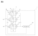
- FIG. 2 is a circuit diagram extracting and showing a controller, a voltage sensor, and a discharge mechanism in the battery control system according to this embodiment.
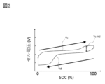
- FIG. 3 is a graph explaining the hysteresis of the secondary battery according to this embodiment.
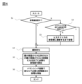
- FIG. 4 is a flowchart showing procedures of a battery control method by the battery control system according to this embodiment.
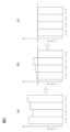
- FIG. 5 is a graph for explaining changes in the cell voltage of the secondary battery in the battery control method according to this embodiment.
- FIG. 1 is a block diagram showing a battery control system according to this embodiment.
- FIG. 2 is a circuit diagram extracting and showing a controller, a voltage sensor, and a discharge mechanism in the battery control system according to this embodiment.
- FIG. 1 shows one secondary battery (battery cell) for convenience, but as shown in FIG. 2, a battery group (battery module) in the present embodiment includes a plurality of secondary batteries. I'm in.
- the battery control system 1 may include a charging device and the like not shown in FIGS. 1 and 2 .
- the battery control system 1 includes a controller 10, a voltage sensor 11, a current sensor 12, a DCDC converter 13, and a discharge mechanism 14.
- Controller 10 is a battery control unit (BCU).
- the controller 10 manages the state of the secondary battery 21 based on the detected voltage detected by the voltage sensor 11 and/or the detected current detected by the current sensor 12, and controls the state of the secondary battery 21 according to the state.
- the SOC usage range of the secondary battery 21 is determined.
- the controller 10 includes a memory such as ROM or RAM, a processor such as CPU, and the like.
- the voltage sensor 11 is a sensor for detecting the voltage across the terminals of the secondary battery 21 . As shown in FIGS. 1 and 2, the voltage sensor 11 is connected between wires connected to the positive and negative electrodes of the secondary battery 21 .
- the current sensor 12 is a sensor for detecting input/output current of the secondary battery 21 .
- the current sensor 12 is connected to wiring connected to the positive electrode or the negative electrode of the secondary battery 21 .
- the voltage sensor 11 and current sensor 12 detect the state of the battery and output the detected values to the controller 10 .
- the battery control system 1 may have a temperature sensor that detects the temperature of the secondary battery 21 .
- the battery control system 1 outputs the temperature of the secondary battery 21 detected by the temperature sensor to the controller 10 .
- the DCDC converter 13 is a power conversion device that converts the voltage input from the secondary battery 21 into a predetermined voltage and outputs power to a load such as a motor.
- the DCDC converter 13 is also a power conversion device that converts a voltage input from a load such as a motor or a charging device into a predetermined voltage and outputs power to the secondary battery 21 .
- This DCDC converter 13 is controlled by the controller 10 .
- a secondary battery 21 is connected to the input side of the DCDC converter 13 , and a load is connected to the output side of the DCDC converter 13 .
- the load is a power grid or the like. That is, the secondary battery 21 is connected to the load via the DCDC converter 13 .
- the discharge mechanism 14 is a circuit for discharging the secondary battery 21.
- the discharge mechanism 14 is electrically connected to the positive and negative electrodes of the secondary battery 21 , and one discharge mechanism 14 is connected to one secondary battery 21 .
- the discharge mechanism 14 has a resistor R and a switch S electrically connected to the resistor R in series.
- the switch S is on/off-controlled by the controller 10 , and when the controller 10 turns on the switch S, the secondary battery 21 is discharged and current flows through the discharge mechanism 14 .
- the discharge mechanism 14 is used for balancing as well as for pre-discharging performed prior to the balancing.
- the battery group 2 includes a plurality of secondary batteries 21.
- the secondary battery 21 is a battery whose open circuit voltage (OCV) during charging is higher than its open circuit voltage during discharging, and is, for example, a lithium ion secondary battery.
- OCV open circuit voltage
- the lithium ion secondary battery include, but are not limited to, those using silicon or an active material containing silicon as the negative electrode active material, or using an active material containing sulfur as the positive electrode active material. can be exemplified.
- an electrolytic solution lithium ion secondary battery may be used, or an all-solid lithium ion secondary battery may be used.
- the positive electrode of such a secondary battery 21 is electrically connected to the negative electrode of another secondary battery 21 via a busbar, although not shown. That is, the plurality of secondary batteries 21 are modularized by being connected to other secondary batteries 21 via busbars.
- the secondary battery 21 is electrically connected to the charging device.
- a charging device connected to secondary battery 21 is, for example, a device for charging secondary battery 21 mounted in an electric vehicle or a hybrid vehicle.
- the secondary battery 21 mounted on the vehicle is charged by taking out the charging cable of the charging device, attaching the charging gun at the tip of the charging cable to the connector of the charging port of the vehicle, and then operating the charging start switch.
- the controller 10 manages the state of charge (SOC) of the secondary battery 21 included in the battery group 2, and controls the DCDC converter 13 and the charging device so that the state of charge of the secondary battery 2 reaches a target state of charge. control each.
- SOC state of charge
- the secondary battery 2 is electrically connected to a load such as a motor as described above.
- the load is a device that operates using the power of the secondary battery 2, and includes a motor that serves as a drive source for the vehicle, auxiliary equipment such as an air conditioner and a light, and the like.
- the discharge of the secondary battery 2 is performed under the control of the controller 10 according to a system request or an external power request.
- a system request corresponds to a command from an in-vehicle computer such as an ECU while the vehicle is running.
- an in-vehicle computer such as an ECU while the vehicle is running.
- an external device such as a mobile terminal so that the temperature inside the vehicle is appropriate when the vehicle starts running.
- a command from the device corresponds to an external power request.
- VGI Vehicle Grid Integration
- FIG. 3 is a graph explaining the hysteresis of the secondary battery according to this embodiment.
- the vertical axis of the graph in FIG. 3 indicates the cell voltage of the secondary battery 21, and the horizontal axis indicates the state of charge (SOC).
- a curve Vc indicates the open circuit voltage when the secondary battery 21 is charged, and a curve Vd indicates the open circuit voltage when the secondary battery 21 is discharged.
- the open circuit voltage Vc during charging is higher than the open circuit voltage Vd during discharging even if the SOC is the same. Become. If balancing is performed without considering this hysteresis, the secondary battery after discharge and the secondary battery after charge will coexist due to hysteresis. When the difference Vc-Vd between Vc and Vd at the same SOC is large (the width of hysteresis is large), the cell voltages of the battery cells deviate greatly after equalizing the SOCs by balancing.
- pre-discharging is performed to discharge the battery by at least the amount of power required for the open-circuit voltage to switch from the open-circuit voltage during charging to the open-circuit voltage during discharging.
- Balancing is performed based on the voltage of the battery after performing the discharge. That is, before balancing, the hysteresis of all the secondary batteries 21 is made equal to the hysteresis during discharge, thereby suppressing the difference in capacity of each battery after balancing.
- a battery control method for the secondary battery 21 using such a battery control system 1 will be described below.
- FIG. 4 is a flow chart showing the procedure of the battery control method by the battery control system according to this embodiment.
- the controller 10 determines whether or not the secondary battery 21 has been left undischarged (preliminary charge/discharge state determination step). Whether or not the secondary battery 21 has been discharged can be determined from the history of current detection values output from the current sensor 12 to the controller 10 before step S1 is executed.
- the controller 10 in this embodiment corresponds to an example of the "preliminary charge/discharge state determination means" in the present invention.
- the state in which the secondary battery 21 is left undischarged means, for example, after the power supply from the secondary battery 21 to the load as described above is stopped, the secondary battery 21 is neither discharged nor charged. It refers to a state in which the battery 21 is left unattended.
- the state in which the secondary battery 21 has not been left after being discharged means, for example, a state in which the secondary battery 21 has been left without being discharged or charged after being charged. , refers to the state immediately after the secondary battery 21 is charged.
- step S1 when the controller 10 determines that the secondary battery 21 is not in a state of being left after discharging (for example, when determining that the secondary battery 21 is in a state of being charged), the process proceeds to step S2.
- the controller 10 determines the difference (Vc-Vd) between the open circuit voltage of the secondary battery 21 during charging and the open circuit voltage of the secondary battery 21 during discharging in the state of charge (SOC) of the secondary battery 21. It is determined whether or not it is equal to or less than the value (hysteresis width confirmation step).
- the controller 10 in this embodiment corresponds to an example of "hysteresis width confirmation means" in the present invention.
- the difference (Vc-Vd) may be small depending on the SOC range.
- the divergence of the cell voltages of the secondary batteries 21 after balancing is unlikely to increase, there is no need to perform pre-discharge in step S3, which will be described later.
- the secondary battery 21 can be prevented from being excessively discharged, the remaining discharge capacity of the secondary battery 21 can be prevented from decreasing.
- the difference (Vc-Vd) is calculated as follows. That is, first, before executing the battery control method of the present embodiment, the open circuit voltage Vc during charging and the open circuit voltage Vd during discharging with respect to the SOC of the secondary battery 21 are measured in advance. Then, in step S2, the controller 10 acquires the open circuit voltage of the secondary battery 21 from the voltage sensor 11 and calculates the SOC from the acquired open circuit voltage. Since the open circuit voltages Vc and Vd for each SOC of the secondary battery 21 are known values from the above measurements, the difference (Vc-Vd) corresponding to the SOC of the secondary battery 21 can be calculated.
- the SOC interval in which the open circuit voltage difference (Vc-Vd) is equal to or less than a predetermined value can be, for example, an SOC of 40% to 60%, preferably 45% to 55%. be able to.
- step S2 if the controller 10 determines that the difference (Vc-Vd) between the open circuit voltage of the secondary battery 21 during charge and the open circuit voltage of the secondary battery 21 during discharge is greater than a predetermined value, step In S3, the controller 10 pre-discharges the secondary battery 21 (pre-discharge step).
- pre-discharging means discharging the secondary battery 21 by at least the amount of electric power that switches the open circuit voltage from the open circuit voltage during charging to the open circuit voltage during discharging.
- the controller 10 discharges the secondary battery 21 by turning on the switch S of the discharge mechanism 14 . This pre-discharge allows the open circuit voltage of the secondary battery 21 to be the open circuit voltage Vd during discharge.
- the discharge mechanism 14 in this embodiment corresponds to an example of the "pre-discharge means" in the present invention.
- the discharge mechanism 14 is used as the pre-discharge means, but it is not limited to this.
- the battery control system 1 may have pre-discharging means separately from the discharging mechanism 14 .
- the amount of power discharged in the pre-discharge varies depending on the type and capacity of the battery. Therefore, it is preferable to calculate this amount of power by discharging the secondary battery 21 and measuring the change in cell voltage in advance before executing the battery control method of the present embodiment.
- Pre-discharging may be performed only for secondary batteries 21 determined to be secondary batteries 21 having an open-circuit voltage at the time of charging, but the open-circuit voltage of all secondary batteries 21 is ensured. It is preferable to perform the test for all the secondary batteries 21 in order to obtain an open circuit voltage during discharge. In particular, by performing this pre-discharging on the secondary battery 21 after charging, after balancing, the secondary battery 21 having an open-circuit voltage during charging and the secondary battery 21 having an open-circuit voltage during discharging. can be effectively prevented from being mixed with.
- the secondary battery 21 After pre-discharging the secondary battery 21 in step S3, the secondary battery 21 waits to relax in step S4. By waiting for relaxation, the cell voltage can be obtained more accurately.
- step S4 When the controller 10 determines in step S1 that the secondary battery 21 is in a state of being left after discharging, the secondary battery 21 is relaxed in step S4. Specifically, the secondary battery 21 is put on standby to relax.
- relaxation means to leave the secondary battery 21 for a predetermined period of time in a state in which charging and discharging of the secondary battery 21 are stopped.
- This predetermined time can be, for example, the time required for the amount of change in the cell voltage of the secondary battery 21 per unit time to fall below a predetermined value.
- the time required for relaxation varies depending on the type of secondary battery and the degree of deterioration, but can be, for example, 30 minutes to 12 hours. Note that if the secondary battery 21 has been left after being charged, and if the remaining time is sufficient for the relaxation of the secondary battery 21, step S4 may be omitted.
- step S3 by determining whether or not pre-discharging (step S3), which will be described later, is necessary, pre-discharging is not performed when pre-discharging is not necessary, thereby preventing the secondary battery 21 from being excessively discharged. can. Therefore, it is possible to prevent the remaining discharge capacity of the secondary battery 21 from decreasing.
- step S5 the controller 10 specifically determines the amount of discharge required for the secondary batteries 21 other than the secondary battery 21 with the minimum capacity to reach the same capacity as the secondary battery with the minimum capacity. calculate.
- step S6 the secondary battery 21 is discharged by the calculated discharge amount (passive balancing step).
- FIG. 5 is a graph for explaining changes in the cell voltage of the secondary battery in the battery control method according to this embodiment.
- FIG. 5 exemplifies changes in cell voltages of four cells A to D. As shown in FIG. 5(a) shows the cell voltage before pre-discharge, FIG. 5(b) shows the cell voltage after pre-discharge, and FIG. 5(c) shows the cell voltage after balancing.
- the cell voltages of the cells A to D decrease due to pre-discharge.
- the cell D with the lowest cell voltage is the cell with the minimum capacity. Therefore, in this example, based on the voltage difference between the cell voltages of cells A to C and the cell voltage VD of cell D, the cell voltages of cells A to C and the cell voltage VD of cell D are the same.
- a discharge amount to be used as a value is calculated for each of the cells A to C.
- the cell voltages of the cells A to C are matched with the cell voltage of the cell D by discharging the cells A to C by the calculated amount of discharge. Thereby, the remaining discharge capacities of the cells A to D can be made substantially uniform.
- a method of matching the remaining discharge capacities of other secondary batteries 21 to the secondary battery 21 with the minimum capacity is exemplified as passive balancing, but the present invention is not limited to this.
- a method is used in which the controller 10 calculates the average value of the cell voltages of all the secondary batteries 21, discharges only the secondary batteries 21 having cell voltages exceeding this average value, and adjusts the cell voltages to the average value.
- You may Active balancing may also be used as a balancing method.
- the circuit for active balancing although not shown, a general balancing circuit for active balancing can be used.
- the SOC can be accurately adjusted by discharging the batteries by the pre-discharging means before executing the balancing.
- the relaxation time of the battery voltage becomes longer due to deterioration, etc., or if the resistance increases, it may not be possible to say that the remaining discharge capacity of a battery with a high cell voltage is large.
- the battery control system 1 and the battery control method of the present embodiment once the discharge is performed in advance, the resistance of the secondary battery 21 increases due to deterioration, and the voltage relaxation time increases. Even when the time is lengthened, the lower the battery voltage is, the lower the battery capacity is, so the capacity can be adjusted more accurately.
Landscapes
- Engineering & Computer Science (AREA)
- Power Engineering (AREA)
- Manufacturing & Machinery (AREA)
- Chemical & Material Sciences (AREA)
- Chemical Kinetics & Catalysis (AREA)
- Electrochemistry (AREA)
- General Chemical & Material Sciences (AREA)
- Secondary Cells (AREA)
- Charge And Discharge Circuits For Batteries Or The Like (AREA)
Abstract
Description
本出願は、2021年12月6日に出願された日本国特許出願の特願2021−197880に基づく優先権を主張するものであり、文献の参照による組み込みが認められる指定国については、上記の出願に記載された内容を参照により本出願に組み込み、本出願の記載の一部とする。
10…コントローラ
11…電圧センサ
12…電流センサ
13…DCDCコンバータ
14…放電機構
R…抵抗
S…スイッチ
2…電池群
21…二次電池
Claims (6)
- 充電時の開回路電圧が放電時の開回路電圧より大きい電池を複数含む電池群において、他の電池の残放電容量よりも大きい残放電容量を有する電池を放電させることで、電池間の残放電容量のバランシングを実行する放電機構を備えた電池制御システムであって、
前記電池制御システムは、前記バランシングの前に、少なくとも開回路電圧が充電時の開回路電圧から放電時の開回路電圧に切替わる電力量だけ前記電池を放電する事前放電を実行する事前放電手段を備え、
前記放電機構は、前記事前放電手段により前記事前放電を実行した後の前記電池の電圧に基づいて、前記バランシングを実行する電池制御システム。 - 請求項1に記載の電池制御システムであって、
前記電池制御システムは、前記事前放電が実行される前に、前記電池群に含まれる前記電池が充電後の状態であるか、又は、放電後の状態であるかを判定する事前充放電状態判定手段を備え、
前記事前放電手段は、前記事前充放電状態判定手段が前記電池を放電後の状態であると判定した場合に、前記事前放電を実行しない電池制御システム。 - 請求項1又は2に記載の電池制御システムであって、
前記電池制御システムは、前記事前放電が実行される前に、前記電池の充電状態(SOC)における、充電時の開回路電圧と放電時の開回路電圧の差を確認するヒステリシス幅確認手段を備え、
前記事前放電手段は、前記ヒステリシス幅確認手段により確認された充電時の開回路電圧と放電時の開回路電圧の差が所定値以下の場合は、前記事前放電を実行しない電池制御システム。 - 請求項1~3のいずれか一項に記載の電池制御システムであって、
前記放電機構は、前記事前放電が完了した後に前記電池の充放電を所定時間停止する緩和操作を実行し、前記緩和操作が完了した後に前記バランシングを実行する電池制御システム。 - 請求項1~4のいずれか一項に記載の電池制御システムであって、
前記事前放電手段は、前記電池群が充電された後に、前記電池群に含まれる全ての前記電池に対して前記事前放電を実行する電池制御システム。 - 充電時の開回路電圧が放電時の開回路電圧より大きい電池を複数含む電池群において、他の電池の残放電容量よりも大きい残放電容量を有する電池を放電させることで、電池間の残放電容量をバランシングするバランシング工程を備える電池制御方法であって、
前記バランシング工程の前に、少なくとも開回路電圧が充電時の開回路電圧から放電時の開回路電圧に切替わる電力量だけ前記電池を放電する事前放電を実行する事前放電工程を備え、
前記バランシング工程は、前記事前放電工程により前記事前放電を実行した後の前記電池の電圧に基づいて、前記バランシングを実行することを含む電池制御方法。
Priority Applications (4)
| Application Number | Priority Date | Filing Date | Title |
|---|---|---|---|
| JP2023565650A JP7677451B2 (ja) | 2021-12-06 | 2022-10-17 | 電池制御システム及び電池制御方法 |
| EP22902490.6A EP4447261A4 (en) | 2021-12-06 | 2022-10-17 | Battery control system and battery control method |
| US18/716,848 US20250038548A1 (en) | 2021-12-06 | 2022-10-17 | Battery Control System and Battery Control Method |
| CN202280080653.8A CN118355582A (zh) | 2021-12-06 | 2022-10-17 | 电池控制系统和电池控制方法 |
Applications Claiming Priority (2)
| Application Number | Priority Date | Filing Date | Title |
|---|---|---|---|
| JP2021-197880 | 2021-12-06 | ||
| JP2021197880 | 2021-12-06 |
Publications (1)
| Publication Number | Publication Date |
|---|---|
| WO2023105280A1 true WO2023105280A1 (ja) | 2023-06-15 |
Family
ID=86729736
Family Applications (1)
| Application Number | Title | Priority Date | Filing Date |
|---|---|---|---|
| PCT/IB2022/000581 Ceased WO2023105280A1 (ja) | 2021-12-06 | 2022-10-17 | 電池制御システム及び電池制御方法 |
Country Status (5)
| Country | Link |
|---|---|
| US (1) | US20250038548A1 (ja) |
| EP (1) | EP4447261A4 (ja) |
| JP (1) | JP7677451B2 (ja) |
| CN (1) | CN118355582A (ja) |
| WO (1) | WO2023105280A1 (ja) |
Cited By (1)
| Publication number | Priority date | Publication date | Assignee | Title |
|---|---|---|---|---|
| JPWO2024084258A1 (ja) * | 2022-10-21 | 2024-04-25 |
Citations (6)
| Publication number | Priority date | Publication date | Assignee | Title |
|---|---|---|---|---|
| JP2010081732A (ja) | 2008-09-26 | 2010-04-08 | Mazda Motor Corp | 自動車のバッテリ制御方法及びその装置 |
| US20120274331A1 (en) * | 2011-04-01 | 2012-11-01 | Liu Albert Shih-Young | Method and Apparatus for Determining the State-of-Charge of a Battery |
| JP2015186339A (ja) * | 2014-03-24 | 2015-10-22 | トヨタ自動車株式会社 | 蓄電システム |
| JP2019087458A (ja) * | 2017-11-08 | 2019-06-06 | 株式会社Gsユアサ | 蓄電素子の管理装置、及び、管理方法 |
| US20210083484A1 (en) * | 2019-04-24 | 2021-03-18 | Contemporary Amperex Technology Co., Limited | Method, apparatus, device and medium for equalization control of battery packs |
| JP2021197880A (ja) | 2020-06-18 | 2021-12-27 | 日本電産トーソク株式会社 | ロータ、およびモータ |
-
2022
- 2022-10-17 CN CN202280080653.8A patent/CN118355582A/zh active Pending
- 2022-10-17 US US18/716,848 patent/US20250038548A1/en active Pending
- 2022-10-17 JP JP2023565650A patent/JP7677451B2/ja active Active
- 2022-10-17 EP EP22902490.6A patent/EP4447261A4/en active Pending
- 2022-10-17 WO PCT/IB2022/000581 patent/WO2023105280A1/ja not_active Ceased
Patent Citations (6)
| Publication number | Priority date | Publication date | Assignee | Title |
|---|---|---|---|---|
| JP2010081732A (ja) | 2008-09-26 | 2010-04-08 | Mazda Motor Corp | 自動車のバッテリ制御方法及びその装置 |
| US20120274331A1 (en) * | 2011-04-01 | 2012-11-01 | Liu Albert Shih-Young | Method and Apparatus for Determining the State-of-Charge of a Battery |
| JP2015186339A (ja) * | 2014-03-24 | 2015-10-22 | トヨタ自動車株式会社 | 蓄電システム |
| JP2019087458A (ja) * | 2017-11-08 | 2019-06-06 | 株式会社Gsユアサ | 蓄電素子の管理装置、及び、管理方法 |
| US20210083484A1 (en) * | 2019-04-24 | 2021-03-18 | Contemporary Amperex Technology Co., Limited | Method, apparatus, device and medium for equalization control of battery packs |
| JP2021197880A (ja) | 2020-06-18 | 2021-12-27 | 日本電産トーソク株式会社 | ロータ、およびモータ |
Non-Patent Citations (1)
| Title |
|---|
| See also references of EP4447261A4 |
Cited By (2)
| Publication number | Priority date | Publication date | Assignee | Title |
|---|---|---|---|---|
| JPWO2024084258A1 (ja) * | 2022-10-21 | 2024-04-25 | ||
| JP7830671B2 (ja) | 2022-10-21 | 2026-03-16 | 日産自動車株式会社 | 電池制御システム、及び、電池制御方法 |
Also Published As
| Publication number | Publication date |
|---|---|
| EP4447261A4 (en) | 2025-04-02 |
| EP4447261A1 (en) | 2024-10-16 |
| JP7677451B2 (ja) | 2025-05-15 |
| CN118355582A (zh) | 2024-07-16 |
| JPWO2023105280A1 (ja) | 2023-06-15 |
| US20250038548A1 (en) | 2025-01-30 |
Similar Documents
| Publication | Publication Date | Title |
|---|---|---|
| US9444267B2 (en) | Cell voltage equalizer for multi-cell battery pack which determines the waiting time between equalization operations based on the voltage difference and the state of charge level | |
| EP3518374B1 (en) | Power supply system | |
| US10090683B2 (en) | Battery management system for controlling an energy storage assembly and method for charging and discharging an energy storage assembly | |
| JP7182110B2 (ja) | 電池システム、電池管理装置 | |
| JP7118935B2 (ja) | 地絡検出装置 | |
| JP5682433B2 (ja) | 充電制御システム | |
| US9438059B2 (en) | Battery control apparatus and battery control method | |
| US9564768B2 (en) | Discharge device for electricity storage device | |
| EP2770575B1 (en) | Apparatus and method for controlling lithium ion secondary battery | |
| CN104471414B (zh) | 电池控制装置 | |
| JP5621818B2 (ja) | 蓄電システムおよび均等化方法 | |
| US9847663B2 (en) | Secondary-battery charging system and method and battery pack | |
| JP2008039515A (ja) | 電池の残存容量検出装置 | |
| EP3300160B1 (en) | Electricity storage device and connection control method | |
| KR102045047B1 (ko) | 배터리 모듈의 soh 불균형을 고려한 최대용량 충전장치 및 그 제어방법 | |
| EP3876384A1 (en) | Battery pack and charging management method thereof | |
| EP3770002B1 (en) | Method for capacitor precharging and capacitance measurement in electric vehicle drive system | |
| JP7677451B2 (ja) | 電池制御システム及び電池制御方法 | |
| KR101794101B1 (ko) | 충전 제어 장치 및 방법 | |
| US20240136826A1 (en) | Equalization control device for battery | |
| JP4196210B2 (ja) | 組電池の充放電制御装置 | |
| CN115693831A (zh) | 蓄电池控制装置、能量存储系统和蓄电池控制方法 | |
| CN109103955A (zh) | 铅酸蓄电池均衡与监控方法及系统 | |
| RU2817426C1 (ru) | Система предзаряда для электрического высокоавтоматизированного транспортного средства категории N3 | |
| US20250158423A1 (en) | Battery system |
Legal Events
| Date | Code | Title | Description |
|---|---|---|---|
| 121 | Ep: the epo has been informed by wipo that ep was designated in this application |
Ref document number: 22902490 Country of ref document: EP Kind code of ref document: A1 |
|
| WWE | Wipo information: entry into national phase |
Ref document number: 2023565650 Country of ref document: JP |
|
| WWE | Wipo information: entry into national phase |
Ref document number: 202280080653.8 Country of ref document: CN Ref document number: 18716848 Country of ref document: US |
|
| WWE | Wipo information: entry into national phase |
Ref document number: 2022902490 Country of ref document: EP |
|
| NENP | Non-entry into the national phase |
Ref country code: DE |
|
| ENP | Entry into the national phase |
Ref document number: 2022902490 Country of ref document: EP Effective date: 20240708 |