WO2023106094A1 - 電動歯ブラシ - Google Patents
電動歯ブラシ Download PDFInfo
- Publication number
- WO2023106094A1 WO2023106094A1 PCT/JP2022/043243 JP2022043243W WO2023106094A1 WO 2023106094 A1 WO2023106094 A1 WO 2023106094A1 JP 2022043243 W JP2022043243 W JP 2022043243W WO 2023106094 A1 WO2023106094 A1 WO 2023106094A1
- Authority
- WO
- WIPO (PCT)
- Prior art keywords
- tooth
- head
- electric toothbrush
- polished
- type
- Prior art date
- Legal status (The legal status is an assumption and is not a legal conclusion. Google has not performed a legal analysis and makes no representation as to the accuracy of the status listed.)
- Ceased
Links
Images







Classifications
-
- A—HUMAN NECESSITIES
- A61—MEDICAL OR VETERINARY SCIENCE; HYGIENE
- A61C—DENTISTRY; APPARATUS OR METHODS FOR ORAL OR DENTAL HYGIENE
- A61C17/00—Devices for cleaning, polishing, rinsing or drying teeth, teeth cavities or prostheses; Saliva removers; Dental appliances for receiving spittle
- A61C17/16—Power-driven cleaning or polishing devices
- A61C17/22—Power-driven cleaning or polishing devices with brushes, cushions, cups, or the like
- A61C17/32—Power-driven cleaning or polishing devices with brushes, cushions, cups, or the like reciprocating or oscillating
- A61C17/34—Power-driven cleaning or polishing devices with brushes, cushions, cups, or the like reciprocating or oscillating driven by electric motor
-
- A—HUMAN NECESSITIES
- A46—BRUSHWARE
- A46B—BRUSHES
- A46B15/00—Other brushes; Brushes with additional arrangements
- A46B15/0002—Arrangements for enhancing monitoring or controlling the brushing process
- A46B15/0004—Arrangements for enhancing monitoring or controlling the brushing process with a controlling means
- A46B15/0006—Arrangements for enhancing monitoring or controlling the brushing process with a controlling means with a controlling brush technique device, e.g. stroke movement measuring device
-
- A—HUMAN NECESSITIES
- A46—BRUSHWARE
- A46B—BRUSHES
- A46B13/00—Brushes with driven brush bodies or carriers
- A46B13/02—Brushes with driven brush bodies or carriers power-driven carriers
- A46B13/026—Brushes which automatically reverse direction of rotation, e.g. using gravity switches
-
- A—HUMAN NECESSITIES
- A46—BRUSHWARE
- A46B—BRUSHES
- A46B15/00—Other brushes; Brushes with additional arrangements
- A46B15/0002—Arrangements for enhancing monitoring or controlling the brushing process
- A46B15/0004—Arrangements for enhancing monitoring or controlling the brushing process with a controlling means
-
- A—HUMAN NECESSITIES
- A46—BRUSHWARE
- A46B—BRUSHES
- A46B15/00—Other brushes; Brushes with additional arrangements
- A46B15/0002—Arrangements for enhancing monitoring or controlling the brushing process
- A46B15/0004—Arrangements for enhancing monitoring or controlling the brushing process with a controlling means
- A46B15/0012—Arrangements for enhancing monitoring or controlling the brushing process with a controlling means with a pressure controlling device
-
- A—HUMAN NECESSITIES
- A61—MEDICAL OR VETERINARY SCIENCE; HYGIENE
- A61C—DENTISTRY; APPARATUS OR METHODS FOR ORAL OR DENTAL HYGIENE
- A61C17/00—Devices for cleaning, polishing, rinsing or drying teeth, teeth cavities or prostheses; Saliva removers; Dental appliances for receiving spittle
- A61C17/16—Power-driven cleaning or polishing devices
- A61C17/22—Power-driven cleaning or polishing devices with brushes, cushions, cups, or the like
- A61C17/221—Control arrangements therefor
-
- A—HUMAN NECESSITIES
- A61—MEDICAL OR VETERINARY SCIENCE; HYGIENE
- A61C—DENTISTRY; APPARATUS OR METHODS FOR ORAL OR DENTAL HYGIENE
- A61C17/00—Devices for cleaning, polishing, rinsing or drying teeth, teeth cavities or prostheses; Saliva removers; Dental appliances for receiving spittle
- A61C17/16—Power-driven cleaning or polishing devices
- A61C17/22—Power-driven cleaning or polishing devices with brushes, cushions, cups, or the like
- A61C17/32—Power-driven cleaning or polishing devices with brushes, cushions, cups, or the like reciprocating or oscillating
- A61C17/34—Power-driven cleaning or polishing devices with brushes, cushions, cups, or the like reciprocating or oscillating driven by electric motor
- A61C17/3409—Power-driven cleaning or polishing devices with brushes, cushions, cups, or the like reciprocating or oscillating driven by electric motor characterized by the movement of the brush body
- A61C17/3418—Rotation around the axis of the toothbrush handle
-
- A—HUMAN NECESSITIES
- A46—BRUSHWARE
- A46B—BRUSHES
- A46B2200/00—Brushes characterized by their functions, uses or applications
- A46B2200/10—For human or animal care
- A46B2200/1066—Toothbrush for cleaning the teeth or dentures
Definitions
- This disclosure relates to an electric toothbrush.
- Patent Literature 1 discloses a technology related to an electric toothbrush that detects and displays the position relative to the teeth of a user, assuming a child, to make the user recognize whether or not the toothbrushing operation was performed correctly.
- the electric toothbrush disclosed in Patent Document 1 includes means for detecting the user's teeth.
- the information obtained by the sensing means is only used to indicate the results of the user's toothbrushing operation. Therefore, with the electric toothbrush, it is difficult to improve the stain removing effect regardless of the user's operating ability.
- An object of the present disclosure is to provide an electric toothbrush that improves dirt removal effect.
- an electric toothbrush specifies a head including a brush portion, a driving portion that operates the head, and the type or position of a tooth to be brushed by the brush portion.
- an input unit and a control unit that determines to which category the type or position of the tooth specified by the input unit belongs, based on specific criteria, and controls the drive unit to change the operation of the head according to the category. And prepare.
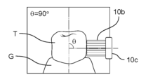
- FIG. 4 is a conceptual diagram when the roll angle of the brush portion with respect to the teeth is 90°;
- FIG. 4 is a conceptual diagram when the roll angle of the brush portion with respect to the teeth is 60°;
- It is a conceptual diagram which shows the pressing direction of the brush part with respect to a tooth
- Fig. 10 is a graph of plaque removal rate versus roll angle on the 6th buccal side of the mandible;
- Fig. 10 is a graph of plaque removal rate versus roll angle on the 5th buccal side of the mandible;
- Fig. 10 is a graph of plaque removal rate versus roll angle on the third buccal side of the mandible;
- Fig. 3 is a graph of plaque removal rate against roll angle on the first buccal side of the mandible.
- Fig. 10 is a graph of plaque removal rate versus roll angle on the sixth lingual side of the mandible;
- Fig. 10 is a graph of plaque removal rate versus roll angle on the fifth lingual side of the mandible.
- Fig. 3 is a graph of plaque removal rate versus roll angle on the third lingual side of the mandible. It is a graph of the plaque removal rate with respect to the roll angle on the most lingual side of the mandible.
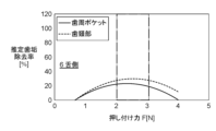
- It is a graph of the plaque removal rate against pressing force on the 6th buccal side of the mandible.
- Fig. 10 is a graph of plaque removal rate versus pressing force on the 5th buccal side of the mandible.
- Fig. 10 is a graph of the plaque removal rate against pressing force on the third buccal side of the mandible. It is a graph of the plaque removal rate against pressing force on the first buccal side of the mandible.
- Fig. 10 is a graph of plaque removal rate versus pressing force on the sixth lingual side of the mandible.
- Fig. 10 is a graph of plaque removal rate versus pressing force on the fifth lingual side of the mandible.
- Fig. 10 is a graph of plaque removal rate against pressing force on the third lingual side of the mandible.
- Fig. 3 is a graph of plaque removal rate versus pressing force on the most lingual side of the mandible.
- Fig. 10 is a side view showing an electric toothbrush according to a second embodiment of the present disclosure;
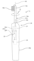
- FIG. 1 is a side view showing an electric toothbrush 1 according to the first embodiment.
- the electric toothbrush 1 includes a head 10 including a brush portion 10b and a handle portion 20 held by a user. By operating the head 10 with respect to the handle portion 20, the electric toothbrush 1 automatically performs a toothbrushing operation or an auxiliary operation thereof.
- the head 10 is a movable part in the electric toothbrush 1.
- the head 10 has a head body 10a and a brush portion 10b.
- the head main body 10a is, for example, a rod-shaped body made of resin.
- the axial direction AX of the head main body 10 a is synonymous with the longitudinal direction of the head 10 .
- a tip portion 10c which is one end portion of the head main body 10a, is a portion that enters the mouth of the user when brushing teeth, and is provided with a brush portion 10b.
- a root portion 10d which is the other end portion of the head body 10a, is connected to a drive portion 21 in the handle portion 20 via a drive shaft 21a.
- the brush part 10b is brought into contact with the user's teeth T or gums G when brushing the teeth (see FIG. 2A, etc. described later).
- the handle portion 20 is a fixed portion of the electric toothbrush 1.
- the handle portion 20 includes a drive portion 21, an operation portion 22, and a control portion 23 inside a handle body 20a.
- the driving section 21 is a power generation section for operating the head 10 .
- the drive unit 21 is, for example, a motor connected to a drive shaft 21a extending toward the inside of the head body 10a.
- the head main body 10a that is, the head 10 can operate as follows by being driven by the driving section 21. As shown in FIG. First, the head 10 vibrates along the axial direction of the head main body 10a as a toothbrushing operation. Further, the head 10 rotates at a roll angle around the axis AX along the axial direction of the head main body 10a as an operation for positioning the brush portion 10b with respect to the teeth T to be polished (see FIG. 2A, etc., which will be described later).
- the head 10 moves so as to apply pressure to the surface of the tooth T or the gingiva G (see FIG. 2A, which will be described later) as an operation of pressing the brush portion 10b against the tooth T to be polished.
- the drive unit 21 may use a linear motor, a rotary motor, or a motor including a swing mechanism that can operate the head 10 as described above.
- the operation part 22 is a push button partially exposed from the inside of the handle body 20a to the outside.
- the operation section 22 is electrically connected to the control section 23 . By pressing the operation unit 22, the user can switch between turning on/off the power, or whether or not to control the operation of the head 10 in this embodiment, which will be described in detail below.
- the control unit 23 is, for example, a control board including a storage unit, and is electrically connected to the driving unit 21.
- the control unit 23 controls the operation of the head 10 by driving the driving unit 21 based on commands from the operation unit 22 .
- the electric toothbrush 1 also includes an input unit 24 for specifying the type or position of the tooth T to be brushed by the brush unit 10b.
- the input section 24 includes a sensor 25 and a detection section 26 .
- the sensor 25 detects a physical quantity required to identify the type or position of the tooth T to be polished.
- the sensor 25 is, for example, an image sensor that photographs the tooth T, a distance sensor that detects the distance to the tooth T, or an acceleration sensor or gyro sensor that detects the movement distance to the tooth T or the attitude of the head 10 with respect to the tooth T. There may be.
- the installation position of the sensor 25 shown in FIG. 1 is an example.
- the sensor 25 may be installed inside the handle body 20a, as shown in FIG. 1, or in the head 10, according to typical usage.
- the detection unit 26 receives the output of the sensor 25 , identifies the type or position of the tooth T to be detected, and transmits it to the control unit 23 . Operation control of the head 10 by the control unit 23 based on information obtained from the detection unit 26 will be described later.
- the electric toothbrush 1 includes, in the handle portion 20, a battery housing portion for housing a battery as a power source for the drive portion 21, and the like.
- the control unit 23 causes the head 10 to start a series of operations.
- the user inserts the brush portion 10b into the oral cavity immediately before or immediately after the head 10 starts to operate.
- the control unit 23 drives the drive unit 21 in accordance with the power-on, and vibrates the drive shaft 21a as a reciprocating motion along the axis AX as a tooth brushing operation. Since the tip of the drive shaft 21a is connected to the head main body 10a, the head 10 also vibrates along the axial direction of the head main body 10a in accordance with the vibration of the drive shaft 21a.
- the tooth brushing operation of the head 10 may be not only a reciprocating motion along the axis AX, but also a reciprocating rotational motion with the axis AX as a central axis, for example.
- control unit 23 controls one or both of the operation of positioning the brush unit 10b and the operation of pressing the brush unit 10b against the tooth T to be polished.
- the drive unit 21 is caused to perform as follows.
- the control unit 23 causes the input unit 24 to specify the type or position of the tooth T to be polished from now on, in both the positioning operation and the pressing operation.
- the sensor 25 detects the tooth T to be polished and transmits the detection result to the detection unit 26 .
- the detection unit 26 identifies the type or position of the tooth T to be polished based on the output of the sensor 25 and transmits the identification result to the control unit 23 .
- the type of tooth T to be polished refers to which tooth T it is among a plurality of teeth T lined up as a row of teeth in the oral cavity.
- the types of teeth T are central incisors (front teeth; No. 1), lateral incisors (front teeth; No. 2), canines (No. 3), and first premolars (No. 4). ), second premolar (number 5), first molar (number 6), second molar (number 7), or third molar (wisdom tooth; number 8).
- the position of the tooth T to be polished refers to the position of either the buccal side, the tongue side or the palate side of the tooth T to be polished.
- the position of the tooth T to be polished is referred to as a tooth in the upper jaw or a tooth in the lower jaw based on whether the tooth T to be polished is in the upper jaw or the lower jaw.
- the position of the tooth T to be polished refers to the tooth on the left side or the tooth on the right side based on whether the tooth T to be polished is on the left side or the right side.
- control unit 23 determines to which category the type or position of the tooth T identified by the input unit 24 belongs, based on specific criteria.
- the control unit 23 determines whether the type of tooth T specified by the input unit 24 belongs to an incisor tooth or a tooth other than an incisor tooth.
- the incisors refer to central incisors or lateral incisors.
- Teeth other than incisors refer to teeth other than central incisors and lateral incisors.
- the control unit 23 may also determine whether the position of the tooth T specified by the input unit 24 to be brushed belongs to the buccal side, the tongue side, or the palate side.
- control unit 23 may determine whether the tooth T specified by the input unit 24 belongs to the tooth in the upper jaw or the tooth in the lower jaw. Alternatively, the control unit 23 determines whether the tooth T specified by the input unit 24 belongs to the tooth on the same side as the hand with which the user grips the handle part 20 or the tooth on the opposite side. may
- control unit 23 controls the operation of the head 10 according to the classification based on the result of determination as to which category the tooth T specified by the input unit 24, that is, the type or position of the tooth T to be polished belongs.
- the driving unit 21 is controlled so as to change the
- the first operation of the head 10 is the operation of positioning the brush part 10b with respect to the tooth T to be polished. Specifically, the drive unit 21 rotates the head body 10a around the axis AX to change the roll angle ⁇ of the head 10, that is, the brush portion 10b.
- FIGS. 2A and 2B are conceptual diagrams showing an example of the roll angle ⁇ when the brush surface of the brush portion 10b is brought into contact with the side surfaces of the tooth T and the gingiva G.
- FIG. it is assumed that the electric toothbrush 1 is maintained in a posture in which the longitudinal direction of the brush portion 10b along the longitudinal direction of the head 10 is approximately parallel to the tooth row direction of the teeth T when brushing the teeth.
- FIG. 2A is a diagram when the roll angle ⁇ is 90°.
- the brush surface of the brush portion 10b abuts on the side surface of the tooth T perpendicular to the direction in which the tooth T grows with respect to the gingiva G, specifically, the direction along the tooth axis.
- FIG. 2B is a diagram when the roll angle ⁇ is 60°.
- the brush surface of the brush portion 10b abuts the tooth T and the gingiva G in a direction approximately towards the tooth neck or periodontal pocket.
- the second action of the head 10 is the action of pressing the brush part 10b against the tooth T to be polished.
- the drive unit 21 moves the head body 10a toward the surface of the tooth T or the gum G to change the pressure applied to the surface of the tooth T or the gum G.
- FIG. the pressure applied to the surface of the tooth T or the gingiva G is referred to as pressing force.
- FIG. 3 is a conceptual diagram showing the pressing direction when the brush portion 10b applies the pressing force F to the side surface of the tooth T.
- the pressing direction of the pressing force F is the direction from the brush surface of the brush part 10b to the side surface of the tooth T along the direction approximately perpendicular to the direction along the tooth axis. .
- the electric toothbrush 1 is set to at least one selected from the group consisting of the roll angle ⁇ and the pressing force F according to the type or position classification of the tooth T to be brushed. In this state, a tooth brushing operation is performed.
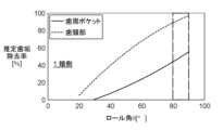
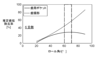
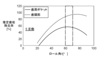
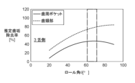
- 4A to 4D are graphs showing the estimated plaque removal rate [%] with respect to the roll angle ⁇ [°] when the electric toothbrush 1 is applied to the buccal side of each type of tooth T in the mandibular model.
- the estimated plaque removal rate is a plaque removal rate estimated from a regression equation based on multiple regression analysis.
- 4A to 4D show both the estimated plaque removal rate in the periodontal pocket and the estimated plaque removal rate in the cervical region.
- the range of the roll angle ⁇ in which the estimated plaque removal rate can take the optimum value is indicated by the dashed-dotted frame.
- FIG. 4A is a graph of the estimated plaque removal rate when the type and position of the tooth T to be polished is on the sixth buccal side of the mandible. In FIG. 4A, it is abbreviated as "6 buccal side” to indicate the difference from other graphs.
- FIG. 4B is a graph of the estimated plaque removal rate when the type and position of the tooth T to be polished is on the fifth buccal side of the lower jaw. In FIG. 4B, it is abbreviated as "5 buccal side”.
- FIG. 4C is a graph of the estimated plaque removal rate when the type and position of the tooth T to be polished is the third buccal side of the mandible. In FIG. 4C, it is abbreviated as "3 buccal side”.
- FIG. 4D is a graph of the estimated plaque removal rate when the type and position of the tooth T to be polished is the first buccal side of the lower jaw. It is abbreviated as "1 buccal side” in FIG. 4D.
- the estimated plaque removal rate according to FIGS. Optimal values can be obtained when ⁇ is in the range of approximately 60° to 70°.
- the estimated plaque removal rate according to FIG. 4D in which the type of tooth T to be polished is classified as an incisor, does not produce peaks for both the periodontal pocket and the tooth neck.
- the optimum value can be obtained at °. From these results, by changing the setting of the roll angle ⁇ according to the classification of whether the type of tooth T to be polished is an incisor tooth or a non-incisor tooth, the intraoral It is presumed that the estimated plaque removal rate can be set to the optimum value for the entire plurality of teeth T.
- 5A to 5D are graphs showing the estimated plaque removal rate [%] with respect to the roll angle ⁇ [°] when the electric toothbrush 1 is applied to the lingual side of each type of tooth T in the mandibular model.
- the conditions for obtaining the estimated plaque removal rate are the same as in FIGS. 4A to 4D.
- FIG. 5A is a graph of the estimated plaque removal rate when the type and position of the tooth T to be polished is the 6th lingual side of the mandible.
- FIG. 5B is a graph of the estimated plaque removal rate when the type and position of the tooth T to be polished is the fifth lingual side of the mandible.
- FIG. 5C is a graph of the estimated plaque removal rate when the type and position of the tooth T to be polished is the third lingual side of the mandible.
- FIG. 5D is a graph of the estimated plaque removal rate when the type and position of the tooth T to be polished is the most lingual side of the mandible. Note that abbreviations such as “6 lingual side” shown in FIGS. 5A to 5D are the same as in FIG. 4A and the like.
- the estimated plaque removal rate according to FIGS. Optimal values can be obtained when ⁇ is in the range of approximately 60° to 70°.
- the estimated plaque removal rate according to FIG. 5D in which the type of teeth T to be polished are classified as incisors, is similar to the estimated plaque removal rate according to FIGS.
- Optimal values can be obtained when is in the range of approximately 60° to 70°. That is, even if the two teeth T are the first lower jaw tooth T, the estimated plaque removal rate according to FIG. 5D for the lingual side is different from the tendency of the estimated plaque removal rate according to FIG. 4D for the buccal side.
- the roll angle ⁇ may be set to approximately 90°.
- the control unit 23 sets the roll angle ⁇ to approximately 60° to 70°. You can set it in the range of °.
- the control unit 23 sets the roll angle ⁇ to a range of approximately 60° to 70°.
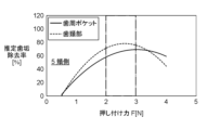
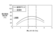
- 6A to 6D are graphs showing the estimated plaque removal rate [%] against the pressing force [N] when the electric toothbrush 1 is applied to the buccal side of each type of tooth T in the mandibular model.
- the estimated plaque removal rate is a plaque removal rate estimated from a regression equation based on multiple regression analysis.
- 6A to 6D show both the estimated plaque removal rate in the periodontal pocket and the estimated plaque removal rate in the cervical region.
- the range of pressing force F that can obtain the optimum value of the estimated plaque removal rate is indicated by a dashed-dotted frame.
- FIG. 6A is a graph of the estimated plaque removal rate when the type and position of the tooth T to be polished is on the 6th buccal side of the lower jaw.
- FIG. 6B is a graph of the estimated plaque removal rate when the type and position of the teeth T to be polished are on the 5th buccal side of the lower jaw.
- FIG. 6C is a graph of the estimated plaque removal rate when the type and position of the tooth T to be polished is the third buccal side of the mandible.
- FIG. 6D is a graph of the estimated plaque removal rate when the type and position of the tooth T to be polished is the first buccal side of the lower jaw. Note that abbreviations such as “6 buccal side” shown in FIGS. 6A to 6D are the same as in FIG. 4A and the like.
- the estimated plaque removal rate according to FIGS. Optimum values can be obtained when F is approximately in the range of 2N to 3N.
- the estimated plaque removal rate according to FIG. 6D in which the type of tooth T to be polished is classified as an incisor, is similar to the estimated plaque removal rate according to FIGS.
- Optimal values can be obtained when is in the range of approximately 2N to 3N. That is, when the position of the tooth T to be polished is on the buccal side of the mandible, the estimated plaque removal rate is There is no big change in the tendency of the pressing force F that can take the optimum value.
- FIGS. 7A to 7D are graphs showing the estimated plaque removal rate [%] against the pressing force [N] when the electric toothbrush 1 is applied to the lingual side of each type of tooth T in the mandibular model.
- the conditions for obtaining the estimated plaque removal rate are the same as in FIGS. 4A to 4D.
- FIG. 7A is a graph of the estimated plaque removal rate when the type and position of the tooth T to be polished is the 6th lingual side of the mandible.
- FIG. 7B is a graph of the estimated plaque removal rate when the type and position of the tooth T to be polished is the fifth lingual side of the mandible.
- FIG. 7C is a graph of the estimated plaque removal rate when the type and position of the tooth T to be polished is the third lingual side of the mandible.
- FIG. 7D is a graph of the estimated plaque removal rate when the type and position of the tooth T to be polished is the most lingual side of the mandible. Note that abbreviations such as “6 lingual side” shown in FIGS. 7A to 7D are the same as in FIG. 4A and the like.
- the estimated plaque removal rate according to FIGS. Optimum values can be obtained when F is approximately in the range of 2N to 3N.
- the estimated plaque removal rate according to FIG. 7D in which the tooth T to be polished is classified as an incisor tooth, does not peak for both the periodontal pocket and the tooth neck, so the pressing force F is approximately 3N.
- Optimal values can be taken when in the range of ⁇ 4N.
- the amount of pressure in the oral cavity is greater than when it is not changed according to the classification. It is presumed that the estimated plaque removal rate can be set to the optimum value for the entire plurality of teeth T.
- the estimated plaque removal rate according to FIG. 7D for the lingual side is different from the tendency of the estimated plaque removal rate according to FIG. 6D for the buccal side. From these results, by changing the setting of the pressing force F depending on whether the position of the tooth T to be polished is on the buccal side or on the lingual side, it is possible to improve the oral cavity more than when it is not changed according to the classification. It is presumed that the estimated plaque removal rate for all of the teeth T can be optimized.
- the control unit 23 only when the type of tooth T to be polished is an incisor tooth and the position to be polished is the lingual side , the pressing force F may be set in the range of approximately 3N to 4N.
- the control unit 23 sets the pressing force F to approximately 2N to 3N. You can set the range.
- the control unit 23 sets the pressing force F to a range of approximately 2N to 3N. good.
- FIGS. 4A to 7D are examples using a mandibular model.
- the lower jaw it is effective to change the setting of the roll angle ⁇ and the like according to the classification as described above. It is also considered effective to change the setting of the roll angle ⁇ and the like according to .
- the description that defines the lingual side for the lower jaw can be interpreted by replacing it with the palatal side for the upper jaw.
- the input unit 24 can determine whether the tooth T to be polished is on the left side or the right side as the position of the tooth T to be polished. In this case, according to the exemplary results of FIGS. 4A to 7D, depending on whether the tooth T to be polished is on the same side or the opposite side of the hand with which the user grips the handle portion 20, It is considered effective to change the settings of the roll angle ⁇ and the like.
- the operation of the head 10 according to the category to which the type or position of the tooth T specified as the target of brushing by the input unit 24 belongs depends on the other category to which the type or position of the other tooth T specified as the target of brushing by the input unit 24 belongs. It may be the same as the operation of head 10, or it may be different.
- case 3 when the type of tooth T specified by the input unit 24 to be polished is a canine tooth (#3) (hereinafter referred to as case 3), the operation of the head 10 in the category to which The operation of the head 10 may be the same as or different from the operation of the head 10 in the category to which the specified type of tooth T is the second molar (number 7) (hereinafter referred to as case 7).
- the operation of the head 10 in the category to which the tooth T specified by the input unit 24 as the target of brushing is located in the lower jaw belongs to the operation specified by the input unit 24 as the target of brushing. It may be the same as or different from the operation of the head 10 in the category to which the tooth T is located on the upper jaw (hereinafter referred to as U).
- the type of tooth T specified by the input unit 24 to be polished is a canine tooth (No. 3) and the position of the tooth T is in the lower jaw (hereinafter referred to as 3L case).
- the operation is classified when the type of the tooth T specified by the input unit 24 to be polished is the second molar (number 7) and the tooth T is located in the upper jaw (hereinafter referred to as the case of 7U). may be the same as the operation of the head 10 in , or may be different.
- the operation of the head 10 remains unchanged regardless of the classification to which the type or position of the tooth T specified as the tooth T to be brushed by the input unit 24 belongs (that is, the operation of the head 10 is always the same regardless of the classification). certain) forms are excluded from this embodiment.
- the electric toothbrush 1 includes a head 10 including a brush portion 10b, a driving portion 21 that operates the head 10, and an input portion 24 that specifies the type or position of a tooth T to be brushed by the brush portion 10b. and In addition, the electric toothbrush 1 determines which category based on specific criteria the type or position of the tooth T specified by the input unit 24 belongs to, and drives the head 10 to change the operation according to the category.
- a control unit 23 for controlling the unit 21 is provided.
- the electric toothbrush 1 is a head 10 including a brush portion 10b; a driving unit 21 for operating the head 10, and an electric/electronic circuit,
- the electrical and electronic circuit during operation, Acquisition of information specifying the type or position of the tooth T to be brushed by the brush part 10b, and whether the type or position of the tooth T specified by the information belongs to which category based on specific criteria is determined, and the operation of the head 10 is changed according to the classification.
- Examples of electrical and electronic circuits are semiconductor devices such as integrated circuits (commonly called “ICs”) or large-scale integrated circuits (commonly called “LSIs").
- ICs integrated circuits
- LSIs large-scale integrated circuits
- the operation of the head is changed depending on which type or position of the tooth T to be brushed belongs to which category based on specific criteria. Therefore, compared to the case where the operation of the head is not changed depending on the type or position of the tooth T to be polished, the removal rate of dental plaque represented by the dirt to be removed is optimized for the plurality of teeth T in the oral cavity as a whole. can be made
- the classification may be based on whether the type of tooth T to be polished is an incisor tooth or a non-incisor tooth.
- the classification may be further based on whether the position of the tooth T to be brushed is on the buccal side, the tongue side, or the palate side.
- the electric toothbrush 1 may include a handle portion 20 including a driving portion 21 .
- Classification may be further based on whether the tooth T to be polished is in the upper jaw or the lower jaw. Classification may be further based on whether the tooth T to be polished is on the same side as the user's hand with which the handle portion 20 is gripped or on the opposite side.
- the operation of the head 10 that changes according to the classification includes (i) rotation about an axis along the longitudinal direction of the head, and (ii) It may be at least one selected from the group consisting of a movement that imparts a pressing force against the tooth surface or gingiva.
- the input unit 24 includes the sensor 25 that detects the tooth T to be brushed, and the type or position of the tooth T to be brushed based on the output of the sensor 25. You may have the detection part 26 which detects.
- control unit 23 can specify the tooth T to be polished in real time in accordance with the toothbrushing operation, and can quickly reflect it in the operation of the head. Or you can save time.
- FIG. 8 is a side view showing the electric toothbrush 2 according to the second embodiment.
- those having the same configuration as the electric toothbrush 1 according to the first embodiment are denoted by the same reference numerals, and descriptions thereof are omitted.
- the sensor 25 for directly detecting the tooth T to be polished is used as the input unit 24 for specifying the type or position of the tooth T to be polished. bottom.
- the electric toothbrush 2 according to the present embodiment as an input unit instead of the input unit 24, information about the type or position of the tooth T to be brushed, which is transmitted from the external communication terminal device 100, is received. You may employ the receiving part 30 which carries out.
- communication terminal device 100 may be a so-called smart phone.
- the user inputs the tooth T to be brushed from the display screen of the communication terminal device 100 before the tooth brushing operation by the electric toothbrush 2, and the communication terminal device 100 transmits the information, so that the receiving unit 30 receives.
- the control unit 23 can identify the type or position of the tooth T to be polished.
- the receiving section 30 as described above may be installed together with the electric toothbrush 1 according to the first embodiment.
- the user after the user finishes brushing teeth with the electric toothbrush 1, the user inputs the tooth T to be treated as finishing from the display screen of the communication terminal device 100, and the communication terminal device 100 transmits the information.
- the electric toothbrush 1 having the receiving unit 30 can perform a toothbrushing operation with a head operation suitable for the tooth T to be treated as finishing.
- the present disclosure is applicable to electric toothbrushes in general that remove dirt from teeth.
Landscapes
- Health & Medical Sciences (AREA)
- Life Sciences & Earth Sciences (AREA)
- Dentistry (AREA)
- Epidemiology (AREA)
- Animal Behavior & Ethology (AREA)
- General Health & Medical Sciences (AREA)
- Public Health (AREA)
- Veterinary Medicine (AREA)
- Biophysics (AREA)
- Brushes (AREA)
Abstract
Description
図1は、第1実施形態に係る電動歯ブラシ1を示す側面図である。電動歯ブラシ1は、ブラシ部10bを含むヘッド10と、使用者が把持するハンドル部20とを備える。電動歯ブラシ1は、ヘッド10をハンドル部20に対して動作させることで、自動で歯磨き動作またはその補助動作を行う。
ブラシ部10bを含むヘッド10、
前記ヘッド10を動作させる駆動部21、および
電気電子回路
を備え、
前記電気電子回路は、動作中に、
前記ブラシ部10bによる磨き対象とされる歯Tの種類または位置を特定する情報を取得し、かつ
前記情報により特定された歯Tの種類または位置が、特定の基準に基づく分類のいずれに属するかを判断し、前記ヘッド10の動作を分類に応じて変化させる。
図8は、第2実施形態に係る電動歯ブラシ2を示す側面図である。電動歯ブラシ2において、第1実施形態に係る電動歯ブラシ1と同一構成のものには同一の符号を付し、説明を省略する。
10 ヘッド
10b ブラシ部
20 ハンドル部
21 駆動部
23 制御部
24 入力部
25 センサー
26 検出部
30 受信部
100 通信端末装置
AX 軸
T 歯
Claims (7)
- ブラシ部を含むヘッドと、
前記ヘッドを動作させる駆動部と、
前記ブラシ部による磨き対象とされる歯の種類または位置を特定する入力部と、
前記入力部が特定した前記歯の種類または位置が、特定の基準に基づく分類のいずれに属するかを判断し、前記ヘッドの動作を前記分類に応じて変化させるように前記駆動部を制御する制御部と、
を備える、電動歯ブラシ。 - 前記分類は、前記磨き対象となる前記歯の種類が切歯か切歯以外かを基準として区分される、請求項1に記載の電動歯ブラシ。
- 前記分類は、前記歯の前記磨き対象となる位置が頬側か舌側または口蓋側かを、さらに基準として区分される、請求項2に記載の電動歯ブラシ。
- 前記駆動部を含むハンドル部を備え、
前記分類は、
前記磨き対象となる前記歯が上顎にあるか下顎にあるか、または、
前記磨き対象となる前記歯が、使用者が前記ハンドル部を把持する手と同じ側にあるか反対側にあるかを、さらに基準として区分される、請求項3に記載の電動歯ブラシ。 - 前記分類に応じて変化する前記ヘッドの動作は、
(i) 前記ヘッドの長手方向に沿った軸を中心軸とした回転、および、
(ii) 前記ヘッドが前記歯の表面または歯肉に対して押し付け力を与える移動
からなる群から選択される少なくとも1つである、
請求項1~4のいずれか一項に記載の電動歯ブラシ。 - 前記入力部は、
前記磨き対象とされる前記歯を検知するセンサーと、
前記センサーの出力に基づいて前記磨き対象とされる前記歯の種類または位置を検出する検出部と、
を有する、
請求項1~5のいずれか一項に記載の電動歯ブラシ。 - 前記入力部は、外部の通信端末装置から送信された、前記磨き対象とされる前記歯の種類または位置に関する情報を受信する受信部である、請求項1~5のいずれか一項に記載の電動歯ブラシ。
Priority Applications (3)
| Application Number | Priority Date | Filing Date | Title |
|---|---|---|---|
| CN202280080940.9A CN118369068A (zh) | 2021-12-08 | 2022-11-22 | 电动牙刷 |
| US18/716,224 US20250024937A1 (en) | 2021-12-08 | 2022-11-22 | Electric toothbrush |
| EP22904025.8A EP4445868A4 (en) | 2021-12-08 | 2022-11-22 | Electric toothbrush |
Applications Claiming Priority (2)
| Application Number | Priority Date | Filing Date | Title |
|---|---|---|---|
| JP2021-198995 | 2021-12-08 | ||
| JP2021198995A JP7857609B2 (ja) | 2021-12-08 | 2021-12-08 | 電動歯ブラシ |
Publications (1)
| Publication Number | Publication Date |
|---|---|
| WO2023106094A1 true WO2023106094A1 (ja) | 2023-06-15 |
Family
ID=86730342
Family Applications (1)
| Application Number | Title | Priority Date | Filing Date |
|---|---|---|---|
| PCT/JP2022/043243 Ceased WO2023106094A1 (ja) | 2021-12-08 | 2022-11-22 | 電動歯ブラシ |
Country Status (5)
| Country | Link |
|---|---|
| US (1) | US20250024937A1 (ja) |
| EP (1) | EP4445868A4 (ja) |
| JP (1) | JP7857609B2 (ja) |
| CN (1) | CN118369068A (ja) |
| WO (1) | WO2023106094A1 (ja) |
Cited By (1)
| Publication number | Priority date | Publication date | Assignee | Title |
|---|---|---|---|---|
| CN120788490A (zh) * | 2025-09-09 | 2025-10-17 | 东莞莱姆森科技建材有限公司 | 一种儿童洗漱用的智能灯镜 |
Citations (2)
| Publication number | Priority date | Publication date | Assignee | Title |
|---|---|---|---|---|
| WO2011083793A1 (ja) * | 2010-01-08 | 2011-07-14 | オムロンヘルスケア株式会社 | 電動歯ブラシ |
| JP2021514739A (ja) * | 2018-03-01 | 2021-06-17 | コーニンクレッカ フィリップス エヌ ヴェKoninklijke Philips N.V. | 口腔ケア装置の位置感知方法 |
Family Cites Families (6)
| Publication number | Priority date | Publication date | Assignee | Title |
|---|---|---|---|---|
| JP5293101B2 (ja) * | 2008-03-14 | 2013-09-18 | オムロンヘルスケア株式会社 | 電動歯ブラシ |
| JP5251265B2 (ja) * | 2008-06-02 | 2013-07-31 | オムロンヘルスケア株式会社 | 電動歯ブラシ |
| CN102427861B (zh) | 2009-05-20 | 2014-10-22 | 博朗有限公司 | 个人身体清洁装置 |
| KR20150080258A (ko) * | 2013-12-31 | 2015-07-09 | 차희찬 | 칫솔질 지도 기능을 구비한 구강 위생 장치 및 이를 포함한 칫솔질 지도 시스템 |
| JP7336688B2 (ja) * | 2020-02-07 | 2023-09-01 | パナソニックIpマネジメント株式会社 | 歯ブラシシステム、および歯ブラシシステム用プログラム |
| CN113729388B (zh) * | 2020-05-29 | 2022-12-06 | 华为技术有限公司 | 控制牙刷的方法、智能牙刷及牙刷系统 |
-
2021
- 2021-12-08 JP JP2021198995A patent/JP7857609B2/ja active Active
-
2022
- 2022-11-22 EP EP22904025.8A patent/EP4445868A4/en active Pending
- 2022-11-22 CN CN202280080940.9A patent/CN118369068A/zh active Pending
- 2022-11-22 US US18/716,224 patent/US20250024937A1/en active Pending
- 2022-11-22 WO PCT/JP2022/043243 patent/WO2023106094A1/ja not_active Ceased
Patent Citations (2)
| Publication number | Priority date | Publication date | Assignee | Title |
|---|---|---|---|---|
| WO2011083793A1 (ja) * | 2010-01-08 | 2011-07-14 | オムロンヘルスケア株式会社 | 電動歯ブラシ |
| JP2021514739A (ja) * | 2018-03-01 | 2021-06-17 | コーニンクレッカ フィリップス エヌ ヴェKoninklijke Philips N.V. | 口腔ケア装置の位置感知方法 |
Non-Patent Citations (1)
| Title |
|---|
| See also references of EP4445868A4 |
Cited By (1)
| Publication number | Priority date | Publication date | Assignee | Title |
|---|---|---|---|---|
| CN120788490A (zh) * | 2025-09-09 | 2025-10-17 | 东莞莱姆森科技建材有限公司 | 一种儿童洗漱用的智能灯镜 |
Also Published As
| Publication number | Publication date |
|---|---|
| CN118369068A (zh) | 2024-07-19 |
| JP2023084741A (ja) | 2023-06-20 |
| US20250024937A1 (en) | 2025-01-23 |
| JP7857609B2 (ja) | 2026-05-13 |
| EP4445868A4 (en) | 2025-03-26 |
| EP4445868A1 (en) | 2024-10-16 |
Similar Documents
| Publication | Publication Date | Title |
|---|---|---|
| CN102046041B (zh) | 电动牙刷 | |
| US8272091B2 (en) | Electric toothbrush and method for controlling thereof | |
| US8839476B2 (en) | Oral care apparatus applied to the removal of dental plaque | |
| CN105411165B (zh) | 交互式口腔清洁工具套装 | |
| US9204713B2 (en) | Process and resulting product for matching a mouthpiece for cleaning teeth to a user's oral geometry | |
| CN102740732B (zh) | 口腔护理装置 | |
| US8079106B2 (en) | Electrical tooth brush | |
| CN102014789B (zh) | 电动牙刷 | |
| JP2013042906A5 (ja) | ||
| US11311363B2 (en) | Toothbrush and system | |
| CN110833463A (zh) | 牙刷控制方法、控制装置及电动牙刷 | |
| CN118058863A (zh) | 电动牙刷的控制方法、装置、电动牙刷及存储介质 | |
| JP2008237276A (ja) | 歯肉マッサージ装置 | |
| JP2009219757A (ja) | 電動歯ブラシ | |
| JP7857609B2 (ja) | 電動歯ブラシ | |
| KR20090106306A (ko) | 자동진동강도조절모듈 및 이를 활용한 전동칫솔 및 그제어방법 | |
| JP7584799B2 (ja) | 電動ブラシ | |
| CN204463125U (zh) | 口腔健康护理系统 | |
| CN114831758A (zh) | 一种自动牙齿清洁器及其牙齿清洁方法 | |
| JPH06169814A (ja) | 歯ブラシおよび電動歯ブラシ | |
| CN118141552A (zh) | 一种电动牙刷 | |
| CN224251532U (zh) | 一种可视的电动牙间隙刷 | |
| CN2520151Y (zh) | 高效自动顺向洗牙装置 | |
| CN121890831A (zh) | 一种具有自适应刷头的牙刷 | |
| JP4738854B2 (ja) | 超音波口内洗浄器 |
Legal Events
| Date | Code | Title | Description |
|---|---|---|---|
| 121 | Ep: the epo has been informed by wipo that ep was designated in this application |
Ref document number: 22904025 Country of ref document: EP Kind code of ref document: A1 |
|
| WWE | Wipo information: entry into national phase |
Ref document number: 18716224 Country of ref document: US |
|
| WWE | Wipo information: entry into national phase |
Ref document number: 202280080940.9 Country of ref document: CN |
|
| WWE | Wipo information: entry into national phase |
Ref document number: 2022904025 Country of ref document: EP |
|
| NENP | Non-entry into the national phase |
Ref country code: DE |
|
| ENP | Entry into the national phase |
Ref document number: 2022904025 Country of ref document: EP Effective date: 20240708 |