WO2023112405A1 - 固体電解質電池及び固体電解質電池の製造方法 - Google Patents
固体電解質電池及び固体電解質電池の製造方法 Download PDFInfo
- Publication number
- WO2023112405A1 WO2023112405A1 PCT/JP2022/033603 JP2022033603W WO2023112405A1 WO 2023112405 A1 WO2023112405 A1 WO 2023112405A1 JP 2022033603 W JP2022033603 W JP 2022033603W WO 2023112405 A1 WO2023112405 A1 WO 2023112405A1
- Authority
- WO
- WIPO (PCT)
- Prior art keywords
- electrode layer
- negative electrode
- solid electrolyte
- layer
- average particle
- Prior art date
- Legal status (The legal status is an assumption and is not a legal conclusion. Google has not performed a legal analysis and makes no representation as to the accuracy of the status listed.)
- Ceased
Links
Images

Classifications
-
- H—ELECTRICITY
- H01—ELECTRIC ELEMENTS
- H01M—PROCESSES OR MEANS, e.g. BATTERIES, FOR THE DIRECT CONVERSION OF CHEMICAL ENERGY INTO ELECTRICAL ENERGY
- H01M10/00—Secondary cells; Manufacture thereof
- H01M10/05—Accumulators with non-aqueous electrolyte
- H01M10/056—Accumulators with non-aqueous electrolyte characterised by the materials used as electrolytes, e.g. mixed inorganic/organic electrolytes
- H01M10/0561—Accumulators with non-aqueous electrolyte characterised by the materials used as electrolytes, e.g. mixed inorganic/organic electrolytes the electrolyte being constituted of inorganic materials only
- H01M10/0562—Solid materials
-
- H—ELECTRICITY
- H01—ELECTRIC ELEMENTS
- H01M—PROCESSES OR MEANS, e.g. BATTERIES, FOR THE DIRECT CONVERSION OF CHEMICAL ENERGY INTO ELECTRICAL ENERGY
- H01M4/00—Electrodes
- H01M4/02—Electrodes composed of, or comprising, active material
- H01M4/36—Selection of substances as active materials, active masses, active liquids
- H01M4/58—Selection of substances as active materials, active masses, active liquids of inorganic compounds other than oxides or hydroxides, e.g. sulfides, selenides, tellurides, halogenides or LiCoFy; of polyanionic structures, e.g. phosphates, silicates or borates
- H01M4/583—Carbonaceous material, e.g. graphite-intercalation compounds or CFx
- H01M4/587—Carbonaceous material, e.g. graphite-intercalation compounds or CFx for inserting or intercalating light metals
-
- H—ELECTRICITY
- H01—ELECTRIC ELEMENTS
- H01M—PROCESSES OR MEANS, e.g. BATTERIES, FOR THE DIRECT CONVERSION OF CHEMICAL ENERGY INTO ELECTRICAL ENERGY
- H01M10/00—Secondary cells; Manufacture thereof
- H01M10/05—Accumulators with non-aqueous electrolyte
- H01M10/052—Li-accumulators
- H01M10/0525—Rocking-chair batteries, i.e. batteries with lithium insertion or intercalation in both electrodes; Lithium-ion batteries
-
- H—ELECTRICITY
- H01—ELECTRIC ELEMENTS
- H01M—PROCESSES OR MEANS, e.g. BATTERIES, FOR THE DIRECT CONVERSION OF CHEMICAL ENERGY INTO ELECTRICAL ENERGY
- H01M10/00—Secondary cells; Manufacture thereof
- H01M10/05—Accumulators with non-aqueous electrolyte
- H01M10/058—Construction or manufacture
-
- H—ELECTRICITY
- H01—ELECTRIC ELEMENTS
- H01M—PROCESSES OR MEANS, e.g. BATTERIES, FOR THE DIRECT CONVERSION OF CHEMICAL ENERGY INTO ELECTRICAL ENERGY
- H01M10/00—Secondary cells; Manufacture thereof
- H01M10/05—Accumulators with non-aqueous electrolyte
- H01M10/058—Construction or manufacture
- H01M10/0585—Construction or manufacture of accumulators having only flat construction elements, i.e. flat positive electrodes, flat negative electrodes and flat separators
-
- H—ELECTRICITY
- H01—ELECTRIC ELEMENTS
- H01M—PROCESSES OR MEANS, e.g. BATTERIES, FOR THE DIRECT CONVERSION OF CHEMICAL ENERGY INTO ELECTRICAL ENERGY
- H01M4/00—Electrodes
- H01M4/02—Electrodes composed of, or comprising, active material
- H01M4/13—Electrodes for accumulators with non-aqueous electrolyte, e.g. for lithium-accumulators; Processes of manufacture thereof
- H01M4/133—Electrodes based on carbonaceous material, e.g. graphite-intercalation compounds or CFx
-
- H—ELECTRICITY
- H01—ELECTRIC ELEMENTS
- H01M—PROCESSES OR MEANS, e.g. BATTERIES, FOR THE DIRECT CONVERSION OF CHEMICAL ENERGY INTO ELECTRICAL ENERGY
- H01M4/00—Electrodes
- H01M4/02—Electrodes composed of, or comprising, active material
- H01M4/13—Electrodes for accumulators with non-aqueous electrolyte, e.g. for lithium-accumulators; Processes of manufacture thereof
- H01M4/139—Processes of manufacture
- H01M4/1393—Processes of manufacture of electrodes based on carbonaceous material, e.g. graphite-intercalation compounds or CFx
-
- H—ELECTRICITY
- H01—ELECTRIC ELEMENTS
- H01M—PROCESSES OR MEANS, e.g. BATTERIES, FOR THE DIRECT CONVERSION OF CHEMICAL ENERGY INTO ELECTRICAL ENERGY
- H01M4/00—Electrodes
- H01M4/02—Electrodes composed of, or comprising, active material
- H01M4/36—Selection of substances as active materials, active masses, active liquids
- H01M4/362—Composites
- H01M4/366—Composites as layered products
-
- H—ELECTRICITY
- H01—ELECTRIC ELEMENTS
- H01M—PROCESSES OR MEANS, e.g. BATTERIES, FOR THE DIRECT CONVERSION OF CHEMICAL ENERGY INTO ELECTRICAL ENERGY
- H01M4/00—Electrodes
- H01M4/02—Electrodes composed of, or comprising, active material
- H01M4/36—Selection of substances as active materials, active masses, active liquids
- H01M4/58—Selection of substances as active materials, active masses, active liquids of inorganic compounds other than oxides or hydroxides, e.g. sulfides, selenides, tellurides, halogenides or LiCoFy; of polyanionic structures, e.g. phosphates, silicates or borates
- H01M4/583—Carbonaceous material, e.g. graphite-intercalation compounds or CFx
-
- H—ELECTRICITY
- H01—ELECTRIC ELEMENTS
- H01M—PROCESSES OR MEANS, e.g. BATTERIES, FOR THE DIRECT CONVERSION OF CHEMICAL ENERGY INTO ELECTRICAL ENERGY
- H01M4/00—Electrodes
- H01M4/02—Electrodes composed of, or comprising, active material
- H01M4/62—Selection of inactive substances as ingredients for active masses, e.g. binders, fillers
-
- H—ELECTRICITY
- H01—ELECTRIC ELEMENTS
- H01M—PROCESSES OR MEANS, e.g. BATTERIES, FOR THE DIRECT CONVERSION OF CHEMICAL ENERGY INTO ELECTRICAL ENERGY
- H01M50/00—Constructional details or processes of manufacture of the non-active parts of electrochemical cells other than fuel cells, e.g. hybrid cells
- H01M50/20—Mountings; Secondary casings or frames; Racks, modules or packs; Suspension devices; Shock absorbers; Transport or carrying devices; Holders
- H01M50/262—Mountings; Secondary casings or frames; Racks, modules or packs; Suspension devices; Shock absorbers; Transport or carrying devices; Holders with fastening means, e.g. locks
-
- H—ELECTRICITY
- H01—ELECTRIC ELEMENTS
- H01M—PROCESSES OR MEANS, e.g. BATTERIES, FOR THE DIRECT CONVERSION OF CHEMICAL ENERGY INTO ELECTRICAL ENERGY
- H01M4/00—Electrodes
- H01M4/02—Electrodes composed of, or comprising, active material
- H01M2004/021—Physical characteristics, e.g. porosity, surface area
-
- H—ELECTRICITY
- H01—ELECTRIC ELEMENTS
- H01M—PROCESSES OR MEANS, e.g. BATTERIES, FOR THE DIRECT CONVERSION OF CHEMICAL ENERGY INTO ELECTRICAL ENERGY
- H01M4/00—Electrodes
- H01M4/02—Electrodes composed of, or comprising, active material
- H01M2004/026—Electrodes composed of, or comprising, active material characterised by the polarity
- H01M2004/027—Negative electrodes
-
- H—ELECTRICITY
- H01—ELECTRIC ELEMENTS
- H01M—PROCESSES OR MEANS, e.g. BATTERIES, FOR THE DIRECT CONVERSION OF CHEMICAL ENERGY INTO ELECTRICAL ENERGY
- H01M2300/00—Electrolytes
- H01M2300/0017—Non-aqueous electrolytes
- H01M2300/0065—Solid electrolytes
- H01M2300/0068—Solid electrolytes inorganic
-
- Y—GENERAL TAGGING OF NEW TECHNOLOGICAL DEVELOPMENTS; GENERAL TAGGING OF CROSS-SECTIONAL TECHNOLOGIES SPANNING OVER SEVERAL SECTIONS OF THE IPC; TECHNICAL SUBJECTS COVERED BY FORMER USPC CROSS-REFERENCE ART COLLECTIONS [XRACs] AND DIGESTS
- Y02—TECHNOLOGIES OR APPLICATIONS FOR MITIGATION OR ADAPTATION AGAINST CLIMATE CHANGE
- Y02E—REDUCTION OF GREENHOUSE GAS [GHG] EMISSIONS, RELATED TO ENERGY GENERATION, TRANSMISSION OR DISTRIBUTION
- Y02E60/00—Enabling technologies; Technologies with a potential or indirect contribution to GHG emissions mitigation
- Y02E60/10—Energy storage using batteries
-
- Y—GENERAL TAGGING OF NEW TECHNOLOGICAL DEVELOPMENTS; GENERAL TAGGING OF CROSS-SECTIONAL TECHNOLOGIES SPANNING OVER SEVERAL SECTIONS OF THE IPC; TECHNICAL SUBJECTS COVERED BY FORMER USPC CROSS-REFERENCE ART COLLECTIONS [XRACs] AND DIGESTS
- Y02—TECHNOLOGIES OR APPLICATIONS FOR MITIGATION OR ADAPTATION AGAINST CLIMATE CHANGE
- Y02P—CLIMATE CHANGE MITIGATION TECHNOLOGIES IN THE PRODUCTION OR PROCESSING OF GOODS
- Y02P70/00—Climate change mitigation technologies in the production process for final industrial or consumer products
- Y02P70/50—Manufacturing or production processes characterised by the final manufactured product
Definitions
- the present invention relates to secondary batteries, and particularly to solid electrolyte batteries.
- Lithium-ion secondary batteries which charge and discharge by absorbing and releasing lithium ions in electrodes, are widely used in various fields, including electric vehicles, as batteries with high energy density.
- a solid electrolyte battery is a battery that uses a solid electrolyte instead of the traditional liquid electrolyte. Since a solid electrolyte battery does not use a liquid electrolyte, it is a highly safe battery with little possibility of ignition even if the discharge capacity per unit weight or unit volume is increased.
- Patent Document 1 discloses a multilayer negative electrode in a lithium ion secondary battery, in which the negative electrode active material is composed of a lower layer containing graphite and an upper layer containing hard carbon.
- solid electrolyte batteries have the problem of requiring a high confining pressure during charging and discharging in order to maintain the adhesion between the positive electrode layer, the solid electrolyte layer, and the negative electrode layer.
- Japanese Patent Laid-Open No. 2002-100002 does not disclose the problem of the confining pressure.
- a solid electrolyte battery including a positive electrode layer, a negative electrode layer, and a solid electrolyte layer formed between the positive electrode layer and the negative electrode layer, wherein the negative electrode layer includes a first negative electrode layer and a first negative electrode layer.
- a laminated second negative electrode layer in contact with the solid electrolyte layer wherein the active material of the first negative electrode layer is crystalline carbon; the active material of the second negative electrode layer is amorphous carbon;
- the negative electrode layer solid electrolyte is mixed in the first negative electrode layer and the second negative electrode layer, and the average particle size (D50) of the negative electrode layer solid electrolyte ⁇ the average particle size (D50) of the amorphous carbon ⁇ the crystallinity
- FIG. 1 is a cross-sectional view of a solid electrolyte battery according to Example 1.
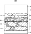
- FIG. 2 is a detailed cross-sectional view of FIG. 1;
- FIG. FIG. 5 is a cross-sectional view of a solid electrolyte battery according to Example 2; 4 is a table comparing configurations and performances of Example 1, Example 2, and Comparative Example.
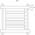
- FIG. 10 is a cross-sectional view of Example 3, and is a schematic cross-sectional view showing a state in which a constraining pressure is applied to the solid electrolyte battery shown in Example 1 using a constraining member.
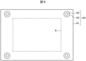
- FIG. 7 is a plan view corresponding to FIG. 6;
- FIG. 7 is a plan view corresponding to FIG. 6;
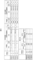
- FIG. 10 is a cross-sectional view of Comparative Example 2, and is a schematic cross-sectional view showing a state in which a constraining pressure is applied to the solid electrolyte battery shown in Comparative Example 1 using a constraining member. It is a cycle test result showing a comparison of the durability of the solid electrolytes of Examples 3 and 4 and Comparative Examples 2 and 3.
- FIG. 1 is a cross-sectional view of a lithium-ion secondary battery, which is a solid electrolyte battery according to Example 1.
- the lithium ion secondary battery has a first negative electrode layer 1, a second negative electrode layer 2, a solid electrolyte layer 3, and a positive electrode layer 4 laminated between a negative electrode collector plate 5 and a positive electrode collector plate 6. It is configured.
- the active material of the first negative electrode layer 1 is crystalline carbon 11 and the active material of the second negative electrode layer 2 is amorphous carbon 21 .
- FIG. 2 is a detailed cross-sectional view of FIG. 1, and is a cross-sectional view showing details of the first negative electrode layer 1, the second negative electrode layer 2, and the solid electrolyte layer 3.
- FIG. 2 the dotted line between the first negative electrode layer and the second negative electrode layer is a virtual line indicating the boundary between the first negative electrode layer and the second negative electrode layer.
- the second negative electrode layer adjacent to the electrolyte layer 3 is provided with amorphous carbon 21 that expands and contracts less than the crystalline carbon 11 due to the insertion/extraction of lithium ions.
- amorphous carbon 21 that expands and contracts less than the crystalline carbon 11 due to the insertion/extraction of lithium ions.
- the first negative electrode layer 1 is composed of crystalline carbon 11 and negative electrode layer solid electrolyte 32 .
- the active material of the first negative electrode layer 1 is crystalline carbon 11, and is formed of graphite, for example.
- Graphite is a layered compound composed of many graphene layers, and Li ions are intercalated or desorbed between the graphene layers.
- the average particle diameter (D50) of the crystalline carbon 11 is preferably about 30 ⁇ m to 2 ⁇ m, for example 16 ⁇ m.
- the average particle size (D50) is referred to as the average particle size or simply as the particle size.
- the average particle size (D50) can be defined as the particle size corresponding to 50% of the volume cumulative amount in the particle size distribution curve.
- Average particle size (D50) can be measured, for example, using a laser diffraction method.
- a method for measuring the average particle diameter (D50) of the positive electrode active material it is introduced into a commercially available laser diffraction particle size distribution measuring device, irradiated with ultrasonic waves, and then equivalent to 50% of the cumulative volume in the measuring device. It is possible to calculate the average particle size (D50) to be used.
- the space between graphite 11, which is crystalline carbon 11, is filled with negative electrode layer solid electrolyte 32, which is fine particles.
- the average particle size of the negative electrode layer solid electrolyte 32 is, for example, 0.5 ⁇ m. That is, the average particle size of the negative electrode layer solid electrolyte 32 ⁇ the average particle size of the crystalline carbon 11 .
- a binder, a conductive aid, and a void are present in the blank portion of the first negative electrode layer 1 . The same applies to the second negative electrode layer 2 and the like.
- the material of the particles of the solid electrolyte 31 forming the solid electrolyte layer 3 may be different from the material of the particles of the anode layer solid electrolyte 32 mixed in the first anode layer 1 and the second anode layer 2 .
- the electrolyte in the solid electrolyte layer 3 is referred to as the solid electrolyte 31
- the solid electrolyte filled in the first anode layer 1 and the second anode layer 2 is referred to as the anode layer solid electrolyte 32.
- the film thickness of the first negative electrode layer 1 is not particularly limited, it is set in the range of about 20 to 500 ⁇ m depending on the required performance of the battery. In Example 1, it is 80 ⁇ m, and in Example 2, it is 48 ⁇ m.
- the second negative electrode layer 2 is composed of amorphous carbon 21 and negative electrode layer solid electrolyte 32 .
- the active material of the second negative electrode layer 2 is amorphous carbon 21, and hard carbon is used, for example.
- Hard carbon is also called “non-graphitizable carbon", and is obtained, for example, by heat-treating a thermosetting resin such as phenolic resin in an inert gas atmosphere.
- a thermosetting resin such as phenolic resin in an inert gas atmosphere.
- the number of graphene layers is small, and Li ions are intercalated or deintercalated not only between graphene layers but also between particles.
- the average particle size of hard carbon, which is amorphous carbon 21, ranges from 1 ⁇ m to 20 ⁇ m, for example, 5 ⁇ m.
- the negative electrode layer solid electrolyte 32 mixed in the second negative electrode layer 2 is the same as the negative electrode layer solid electrolyte 32 mixed in the first negative electrode layer. That is, the average particle size of the negative electrode layer solid electrolyte 32 is, for example, 0.5 ⁇ m, which is smaller than the average particle size of the crystalline carbon 11 . Also, the average particle size of the amorphous carbon 21 is smaller than the average particle size of the crystalline carbon 11 .
- the thickness of the second negative electrode layer 2 is not particularly limited, but is set in the range of about 5 to 500 ⁇ m depending on the required performance of the battery. However, if the second negative electrode layer 2 is thick, the battery capacity will decrease, so the thickness of the second negative electrode layer 2 is desirably 120 ⁇ m or less in order to keep the battery capacity at a high value. In Example 1, the thickness of the second negative electrode layer is 12 ⁇ m, and in Example 2, the thickness of the second negative electrode layer 2 is 84 ⁇ m.
- the active material is amorphous carbon 21
- the amorphous carbon 21 is hard, there are problems such as increased contact resistance with the negative electrode layer solid electrolyte 32 .
- the average particle size of the negative electrode layer solid electrolyte 32 is made smaller than the average particle size of the amorphous carbon 21, thereby suppressing the increase in contact resistance.
- the amorphous carbon 21 used as the active material of the second negative electrode layer 2 may be soft carbon.
- Soft carbon is also called “easily graphitizable carbon”, and has a mixture of amorphous parts, turbostratic structure, and graphite-like structure. For example, it can be obtained by heat-treating pitch-based carbon or a thermoplastic resin.
- hard carbon is used as the amorphous carbon 21 in the following examples, similar performance can be obtained even when soft carbon is used.
- a solid electrolyte layer 3 is formed on the second negative electrode layer 2 .
- the solid electrolyte 31 used for the solid electrolyte layer 3 includes an oxide system and a sulfide system.
- oxide-based solid electrolytes include Li7La3Zr2O12-Zr2O12 (LLZ) and Li3BO3-Li2SO4.
- sulfide-based solid electrolytes include Li10GeP2S12 (LGPS) and Li6PS5Cl-based (aldirodite).
- Li6PS5Cl system (aldirodite) is used among sulfide system solid electrolytes which can reduce electric resistance and is more advantageous for output characteristics.
- the solid electrolyte 31 in the present invention is not limited to the Li6PS5Cl system (aldirodite), and other solid electrolytes can be used.
- the thickness of the solid electrolyte layer 3 is, for example, 0.1 ⁇ m to 300 ⁇ m, preferably 10 ⁇ m to 30 ⁇ m.
- the solid electrolyte 31 forming the solid electrolyte layer 3 and the negative electrode layer solid electrolyte 32 mixed in the first negative electrode layer 1 and the second negative electrode layer 2 are different.
- the average particle size of the negative electrode layer solid electrolyte 32 is smaller than the average particle size of the solid electrolyte 31 forming the solid electrolyte layer 3 .
- the solid electrolyte 31 and the anode layer solid electrolyte 32 may be made of the same material. In Examples 1 and 2, the materials of the solid electrolyte 31 and the anode layer solid electrolyte 32 are the same.
- the average particle size of the negative electrode layer solid electrolyte 32 mixed in the layer 2 is equal to the average particle size.
- the average particle size of the solid electrolyte 31 forming the solid electrolyte layer 3>the average particle size of the negative electrode layer solid electrolyte 32 mixed in the first negative electrode layer 1 and the second negative electrode layer 2 is established.
- the present invention can have the following configuration in addition to the configuration described above.
- the first configuration is that the average particle size of the negative electrode layer solid electrolyte 32 of the first negative electrode layer 1 is smaller than the average particle size of the crystalline carbon 11, preferably 1/10 or less.
- This configuration improves the adhesion between the crystalline carbon 11 that constitutes the active material in the first negative electrode layer 1 and the negative electrode layer solid electrolyte 32 disposed therearound. Even after charge-discharge cycles, it is possible to suppress deterioration in adhesion due to cycles of expansion and contraction of the active material (for example, crystalline carbon 11), and to suppress increase in battery resistance. In addition, it is possible to obtain the effect of suppressing the formation of lithium dendrites during rapid charging.
- the second configuration is that the average particle size of the negative electrode layer solid electrolyte 32 of the second negative electrode layer 2 is smaller than the average particle size of the amorphous carbon 21, preferably 1/10 or less.
- This configuration improves the adhesion between the amorphous carbon 21 that constitutes the active material in the second negative electrode layer 2 and the negative electrode layer solid electrolyte 32 that is arranged therearound. Even after charge/discharge cycles, it is possible to suppress deterioration in adhesion due to cycles of expansion and contraction of the active material (for example, amorphous carbon 21), and to suppress increase in battery resistance. In addition, it is possible to obtain the effect of suppressing the formation of lithium dendrites during rapid charging.
- the third configuration is that the average particle size of the negative electrode layer solid electrolyte 32 of the second negative electrode layer 2 is smaller than the average particle size of the negative electrode layer solid electrolyte 32 of the first negative electrode layer 1 . Since the second negative electrode layer 2 is close to the solid electrolyte layer 3, the reaction is more active. According to the third configuration, high adhesion between the active material 21 and the first negative electrode layer solid electrolyte 32 can be obtained in the second negative electrode layer 2 where the reaction is active, so the battery resistance increases after charge-discharge cycles. can be obtained, such as suppressing the generation of lithium dendrites in rapid charging.
- a fourth configuration is that the average particle size of the negative electrode layer solid electrolyte 32 of the second negative electrode layer 2 is smaller than the average particle size of the negative electrode layer solid electrolyte 32 of the first negative electrode layer 1 .
- high adhesion between the crystalline carbon 11 and the negative electrode layer solid electrolyte 32 can be obtained in the first negative electrode layer 1 having the crystalline carbon 11 having a larger expansion coefficient than the amorphous carbon 21. can be done.
- the first negative electrode layer 1 and the solid electrolyte layer 3 are arranged with the second negative electrode layer 2 interposed therebetween. It is possible to suppress the deterioration of the adhesion at the interface with the layer of and further suppress the increase in electrical resistance.
- the average particle shape of the solid electrolyte 31 and the average particle shape of the negative electrode layer solid electrolyte 32 may be the same. According to this configuration, the handling of the solid electrolyte is excellent in terms of cost.
- the film thickness can be easily controlled, and productivity can be improved.
- the present invention includes various forms.
- the anode layer solid electrolyte mixed in the first anode layer 1 and the second anode layer 2 is simply referred to as the anode layer solid electrolyte 32 unless otherwise specified. called.
- the average particle size of the negative electrode layer solid electrolyte 32 is preferably 1/10 or less of the average particle size of the amorphous carbon 21. This is because if the ratio is 1/10 or less, the negative electrode layer solid electrolyte 32 can be easily arranged on the outer edge of the relatively large amorphous carbon 21, and the contact resistance between the negative electrode layer solid electrolyte 32 and the amorphous carbon 21 can be reduced. .
- the average particle size of the negative electrode layer solid electrolyte 32 can be reduced to about 0.1 ⁇ m.
- the average particle size of the negative electrode layer solid electrolyte 32 is 0.5 ⁇ m, and the average particle size of the amorphous carbon 21 of the second negative electrode layer 2 is 5 ⁇ m.
- the average particle size/average particle size of the amorphous carbon 21 of the second negative electrode layer 2 is 1/10. Even if the average particle size of the negative electrode layer solid electrolyte 32 is other than 0.5 ⁇ m or the average particle size of the amorphous carbon 21 of the second negative electrode layer 2 is other than 5 ⁇ m, (the average particle size of the negative electrode layer solid electrolyte 32
- the ratio of grain size/average grain size of the amorphous carbon 21 in the second negative electrode layer 2) is preferably 1/10 or less.
- the negative electrode has a two-layer structure, and the energy density of the second negative electrode layer 2 using hard carbon as an active material is lower than the energy density of the first negative electrode layer 1 using graphite as an active material. . Therefore, when it is desired to increase the energy density of the lithium ion secondary battery, the thickness of the second negative electrode layer 2 using hard carbon is reduced. In this case, for example, the thickness of the second negative electrode layer 2 is smaller than the thickness of the solid electrolyte layer 3 .
- the positive electrode layer 4 is laminated on the solid electrolyte layer 3.
- the positive electrode layer 4 used in the present invention is not particularly limited.
- the positive electrode active material may be LiCoO2 (lithium cobalt oxide) or LiNiO2 (lithium nickel oxide), which is a layered rock salt type composite oxide positive electrode material, or LiMn2O4 (manganese lithium oxide) and the like can be used.
- the average particle size of the positive electrode active material is not particularly limited, but is, for example, 0.1 to 50 ⁇ m. Also, the thickness of the positive electrode layer is not particularly limited, but is, for example, 0.5 ⁇ m to 500 ⁇ m.
- a positive collector plate 6 is arranged on the positive electrode layer 4 .
- the method for manufacturing the lithium ion secondary battery shown in FIGS. 1 and 2 will be described in detail below.
- a material of the negative electrode current collector plate 5 for example, stainless steel, copper, nickel, carbon, or the like can be used.
- the thickness of the negative electrode current collector plate 5 is, for example, 1 ⁇ m to 20 ⁇ m.
- a stainless steel foil with a thickness of 10 ⁇ m was used as the negative electrode current collector plate 5 .
- the positive electrode current collector plate 6 can be used as the material of the positive electrode current collector plate 6 .
- the thickness of the positive collector plate 6 is, for example, 1 ⁇ m to 20 ⁇ m. In Example 1, an aluminum foil having a thickness of 20 ⁇ m was used as the positive electrode current collector plate 6 .
- the first negative electrode layer 1 was manufactured as follows. In Example 1, graphite is used as the crystalline carbon 11 as the active material of the first negative electrode layer 1 . Graphite 11, negative electrode layer solid electrolyte 32, and a binder were mixed, and a solvent was added to prepare a slurry. This slurry was applied onto the negative electrode current collector plate 5 so as to have a target basis weight. Then, it was made to dry, the solvent was blown off, and the 1st negative electrode layer 1 was created.
- Example 1 the average particle size of graphite as the first negative electrode layer 1 is 16 ⁇ m.
- the negative electrode layer solid electrolyte 32 mixed with graphite used Li6PS5Cl system (aldirodite) with an average particle size of 0.5 ⁇ m.
- the thickness of the first negative electrode layer was 80 ⁇ m.
- the second negative electrode layer 2 was also basically produced in the same process as the first negative electrode layer 1 .
- hard carbon is used as the amorphous carbon 21 as the active material of the second negative electrode layer 2 .
- Hard carbon 21, negative electrode layer solid electrolyte 32, and binder were mixed, and a solvent was added to prepare slurry. This slurry was applied onto a PET (Polyethylene Terephthalate) substrate so as to have a target basis weight. Then, it was made to dry, the solvent was blown off, and the 2nd negative electrode layer 2 was created.
- PET Polyethylene Terephthalate
- the average particle size of the hard carbon 21 as the second negative electrode layer 2 is 5 ⁇ m.
- the negative electrode layer solid electrolyte 32 mixed with hard carbon is Li6PS5Cl-based (aldirodite) having an average particle size of 0.5 ⁇ m.
- the thickness of the second negative electrode layer 2 was set to 12 ⁇ m. The thinner the second negative electrode layer 2 is, the higher the energy density of the battery can be, but the formation of the layer becomes difficult.
- a laminate in which a first negative electrode layer 1 is formed on a negative electrode current collector plate 5 and a laminate in which a second negative electrode layer 2 is formed on a PET substrate are divided into a first negative electrode layer 1 and a second negative electrode layer 2.
- the second negative electrode layer 2 was bonded onto the first negative electrode layer 1 by roll pressing.
- the PET substrate was separated from the second negative electrode layer 2 , and a laminate of the first negative electrode layer 1 and the second negative electrode layer 2 was formed on the negative electrode current collector plate 5 .
- Such a lamination method by bonding has the advantage that the first negative electrode layer 1 and the second negative electrode layer 2 can be formed under optimum conditions.
- the structure in which the second negative electrode layer 2 is laminated on the first negative electrode layer 1 can also be formed by a method of coating the second negative electrode layer 2 on the first negative electrode layer 1, in addition to the above. That is, on the negative electrode current collector plate 5, as described above, the first negative electrode layer 1 is formed, and the slurry for forming the second negative electrode layer 2 is applied thereon. 2 a negative electrode layer 2 is laminated on the first negative electrode layer 1;
- the solid electrolyte 31 in the solid electrolyte layer 3 As the solid electrolyte 31 in the solid electrolyte layer 3, the solid electrolyte 31 made of a Li6PS5Cl system (aldirodite) was used, but the average particle size was larger than the average particle size of the negative electrode layer solid electrolyte 32. A solid electrolyte 31 and a binder were mixed, and a solvent was added to prepare a slurry. This slurry was applied onto a PET (polyethylene terephthalate) substrate. After that, the solid electrolyte layer 3 was formed by drying to remove the solvent. The thickness of the solid electrolyte layer 3 was set to 20 ⁇ m.
- a laminated body in which the first negative electrode layer 1 and the second negative electrode layer 2 are formed on the negative electrode current collector plate 5 and a laminated body in which the solid electrolyte layer 3 is formed on the PET substrate are referred to as the second negative electrode layer 2.
- the solid electrolyte layers 3 were stacked so as to face each other, and the solid electrolyte layer 3 was bonded onto the second negative electrode layer 2 by roll pressing. After that, the PET substrate was peeled off from the solid electrolyte layer 3 to prepare a laminate in which the first negative electrode layer 1 , the second negative electrode layer 2 and the solid electrolyte layer 3 were formed on the negative electrode current collector plate 5 .
- the structure in which the solid electrolyte layer 3 is laminated on the laminate of the first negative electrode layer 1 and the second negative electrode layer 2 can be obtained by applying the solid electrolyte layer 3 on the second negative electrode layer 2 in addition to the above. can also be formed. That is, the first negative electrode layer 1 and the second negative electrode layer 2 are formed on the negative electrode collector plate 5 as described above, and the slurry for forming the solid electrolyte layer 3 is applied thereon. After drying, the solid electrolyte layer 3 is laminated on the second negative electrode layer 2 .
- a positive electrode active material, a solid electrolyte, and a binder were mixed, and a solvent was added to prepare slurry. This slurry was applied onto the positive electrode current collector plate 6 so as to have a target basis weight. Then, it was dried to remove the solvent, and the positive electrode layer 4 was formed.
- the positive electrode active material LiNi 0.5 Co 0.2 Mn 0.3 (lithium-nickel-cobalt-manganese oxide), which is a layered rock salt type composite oxide positive electrode material having an average particle size of 4 ⁇ m, was used. In Example 1, the thickness of the positive electrode layer 4 was set to 80 ⁇ m.
- the lithium ion secondary battery of Example 1 is manufactured by the above process.
- Example 1 the configurations of the first negative electrode layer 1 and the second negative electrode layer 2 are described in the row of Example 1 in the upper table of FIG.
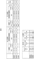
- the table on the upper side of FIG. 4 shows examples of physical configurations of the first negative electrode layer 1 and the second negative electrode layer 2 in Examples 1, 2, and Comparative Example.
- the table on the lower side of FIG. 4 describes the characteristics of Example 1, Example 2, and Comparative Example. A characteristic comparison will be described later.
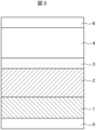
- FIG. 3 is a cross-sectional view of a lithium ion secondary battery, which is a solid electrolyte battery according to Example 2.
- FIG. The specific materials of the first negative electrode layer 1, the second negative electrode layer 2, the solid electrolyte layer 3, and the positive electrode layer 4 in Example 2 are the same as those in Example 1.
- Example 2 differs from Example 1 in the thickness of each layer.
- the thickness of the first negative electrode layer 1 in Example 2 is 48 ⁇ m, and the thickness of the second negative electrode layer 2 is 84 ⁇ m.
- the thickness of the first negative electrode layer 1 is 80 ⁇ m
- the thickness of the second negative electrode layer 2 is 12 ⁇ m.
- Example 2 the influence of the second negative electrode layer 2 using the hard carbon 21 as an active material is more pronounced.
- Example 2 the total thickness of the first negative electrode layer 1 and the second negative electrode layer 2 is larger than in Example 1.
- the average particle size of the crystalline carbon 11 that is the active material of the first negative electrode layer 1>the average particle size of the amorphous carbon 21 that is the active material of the second negative electrode layer 2>the first negative electrode layer 1 and the second negative electrode is the average particle size of the negative electrode layer solid electrolyte 32 mixed in the layer 2;
- the average particle size of the solid electrolyte 31 forming the solid electrolyte layer 3 > the average particle size of the negative electrode layer solid electrolyte 32 mixed in the first negative electrode layer 1 and the second negative electrode layer 2 .
- Example 2 also, by adopting the following configuration, in the same manner as described in Example 1, the increase in battery resistance after charge-discharge cycles is suppressed, and rapid charging is performed. Effects such as suppressing the formation of lithium dendrites can be obtained. That is, the first configuration is that the average particle size of the negative electrode layer solid electrolyte 32 of the first negative electrode layer 1 is smaller than the average particle size of the crystalline carbon 11, preferably 1/10 or less. A second configuration is that the average particle size of the negative electrode layer solid electrolyte 32 of the second negative electrode layer 2 is smaller than the average particle size of the amorphous carbon 21, preferably 1/10 or less.
- a third configuration is that the average particle size of the negative electrode layer solid electrolyte 32 of the second negative electrode layer 2 is smaller than the average particle size of the negative electrode layer solid electrolyte 32 of the first negative electrode layer 1 .
- a fourth configuration is that the average particle size of the negative electrode layer solid electrolyte 32 of the second negative electrode layer 2 is smaller than the average particle size of the negative electrode layer solid electrolyte 32 of the first negative electrode layer 1 .
- each layer such as the first negative electrode layer 1, the second negative electrode layer 2, the solid electrolyte layer 3, the positive electrode layer 4, etc. is the same as that of the first embodiment.
- the structures of Example 2 are described in the row of Example 2 in the upper table of FIG.
- the table on the lower side of FIG. 4 describes the characteristics in Example 1, Example 2, and Comparative Example. A characteristic comparison will be described later.
- the negative electrode layer is formed of one layer as in the conventional case.
- Graphite which is crystalline carbon 11, is used as the active material of the negative electrode layer.
- the average particle size of graphite is, for example, 16 ⁇ m.
- the thickness of the negative electrode layer is 87 ⁇ m.
- the method of forming the negative electrode layer is the same as the method of manufacturing the first negative electrode layer 1 of the first embodiment.
- the configurations and lamination methods of the solid electrolyte layer 3 and the positive electrode layer 4 are also the same as those described in the first embodiment.
- FIG. 4 is a table comparing Example 1, Example 2, and Comparative Example. This is a table with The negative electrode layer of the comparative example is one layer and has the same structure as the first negative electrode layer, so it is described in the column of the first negative electrode layer.
- the thickness ratio at the right end of the upper table is (thickness of second negative electrode layer)/(thickness of first negative electrode layer+thickness of second negative electrode layer).
- the table on the lower side of FIG. 4 compares the performance of the lithium ion secondary batteries according to Example 1, Example 2, and Comparative Example.
- the performance comparison of lithium-ion secondary batteries is based on energy density (%), durability, and input characteristics.
- the energy density of the battery is greater when graphite is used for the negative electrode than when hard carbon is used. Therefore, the comparative example has the highest energy density.
- DCR direct current resistance
- the input characteristics are evaluated at 25°C, with the discharge capacity at 0.1C as the denominator, and the charge capacity rate at which 4.35V is reached at 4C and 6C charging.
- 0.1 C means that the battery is fully charged in 10 hours from a completely discharged state.
- 4C means fully charging in 1/4 hour from a completely discharged state.
- Example 1 the 4C charge is 52% and the 6C charge is 37%. In Example 2, the 4C charge is 41% and the 6C charge is 25%.
- the comparative example Li dendrite was deposited during charging, the negative electrode and the positive electrode were short-circuited, and the voltage did not reach 4.35V.
- a highly reliable and durable lithium ion secondary battery can be realized.
- precipitation of Li dendrites can be suppressed. Therefore, it is possible to lower the rigidity of the jig (metal plate) for restraining the housing, and it is possible to reduce the weight of the battery. The detailed reasons are as follows.
- the solid electrolyte battery including the laminate as described above can suppress an increase in resistance after charge-discharge cycles.
- lithium deposition can be suppressed during high-rate charging.
- effects such as suppression of short circuit and reduction of battery restraint pressure can be obtained.
- a solid electrolyte battery it is conceivable to sandwich the battery between metal plates and constrain it from the outside in order to suppress the risk of lithium dendrites being deposited in the voids during high-rate charging and causing an internal short circuit in the battery.
- the higher the confining pressure the higher the rigidity of the metal plate. Therefore, it is important to prevent the increase in weight and volume of the metal plate from leading to a decrease in energy density. Confining pressure can be reduced by this solid electrolyte battery.
- Examples 3 and 4 shown below are configurations in which confining pressure is applied to the solid electrolyte battery of Example 1.
- Comparative Examples 2 and 3 are configuration examples in which confining pressure is applied to the solid electrolyte battery according to Comparative Example 1.
- FIG. FIG. 8 is a table comparing battery durability between the structures of Examples 3 and 4 and the structures of Comparative Examples 2 and 3. In FIG.
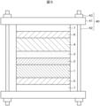
- FIG. 5 is a cross-sectional view of a solid electrolyte battery according to Example 3.
- FIG. FIG. 5 is a cross-sectional view showing a state in which pressure is applied to the solid electrolyte battery of Example 1 using a binding member 40.
- the cross section of FIG. 5 is a schematic cross section for giving an image of the confining pressure. That is, in an actual solid electrolyte battery, the structures of the first to sixth layers shown in Example 1 are wound in many layers via insulating sheets and housed in a battery case. Then, it receives pressure from the outside of the battery case using, for example, a support plate or the like shown in FIG. The same applies to Example 4 and Comparative Examples 2 and 3.
- a first negative electrode layer 1, a second negative electrode layer 2, a solid electrolyte layer 3, and a positive electrode layer 4 are sandwiched between a negative electrode collector plate 5 and a positive electrode collector plate 6.
- the first negative electrode layer 1 , the second negative electrode layer 2 and the solid electrolyte layer 3 are mixed with the negative electrode solid electrolyte 32 .
- the restraining member 40 is composed of a support plate 41, a bolt 42, and a nut 43 that sandwich the solid electrolyte battery from above and below with an insulating sheet 7 interposed therebetween.
- long bolts 42 and nuts 43 are used to fasten upper and lower support plates 41 to apply a restraining pressure to the solid electrolyte battery.
- FIG. 6 is a plan view of FIG. 5 viewed from above.
- Bolts 42 and nuts 43 for fastening the upper and lower support plates 41 are arranged at the four corners of the support plate 41 . Since the support plate 41 applies pressure to the solid electrolyte battery from above and below, a certain degree of rigidity is required. For products, for example, SUS with a thickness of about 10 mm is used. However, since the energy density of the battery is counted including the binding member 40, the weight of the binding member 40 should be as small as possible. However, if the restraining pressure is small, the durability of the battery cannot be ensured.
- Example 3 since the solid electrolyte battery having the structure of Example 1 according to the present invention is used, the confining pressure can be small.
- the confining pressure in Example 3 is 0.1 t/cm 2 .
- t is tons.
- the durability of the solid electrolyte battery at this time was evaluated by DCR (%) and capacity retention rate (%) after 300 cycles at 60°C. The results are shown in FIG. 8, which shows better durability than the comparative example. Details of FIG. 8 will be described later.
- Example 4 The structure of Example 4 is the same as that of Example 3. That is, as shown in FIGS. 5 and 6, the solid electrolyte battery of Example 1 is clamped and applied with a restraining pressure by a restraining member 40 .
- the confining pressure in Example 4 is 0.05 t/cm 2 which is smaller than that in Example 3.
- FIG. 8 shows the durability of the solid electrolyte battery in this case. Although the details of FIG. 8 will be described later, this example also exhibits durability superior to that of the comparative example.
- FIG. 7 is a cross-sectional view of a solid electrolyte battery according to Comparative Example 2.
- FIG. FIG. 7 is a cross-sectional view showing a state in which pressure is applied to the solid electrolyte battery of Comparative Example 1 using a restraining member 40 through an insulating sheet 7.
- FIG. The cross section of FIG. 7 is a schematic cross section for giving an image of the confining pressure. As shown in FIG. 7, in Comparative Examples 1 and 2, the second negative electrode layer does not exist.
- a plan view of FIG. 7 viewed from above is the same as FIG.
- the confining pressure in Comparative Example 1 is the same as in Example 3, 0.1 t/cm 2 .
- FIG. 8 shows the durability of the solid electrolyte battery in this case. Details of FIG. 8 will be described later.
- Comparative Example 3 The structure of Comparative Example 3 is the same as that of Comparative Example 2. That is, as shown in FIG. 7, the solid electrolyte battery of Comparative Example 1 is tightened and applied with a restraining pressure by a restraining member 40 .
- the confining pressure in Comparative Example 3 is 0.05 t/cm 2 , which is smaller than in Comparative Example 2.
- FIG. 8 shows the durability of the solid electrolyte battery in this case.
- FIG. 8 is a table comparing Example 3, Example 4, Comparative Example 2, and Comparative Example 3, and the upper table is a table showing the configuration in each Example and Comparative Example described above.
- Comparative Examples 2 and 3 have only one negative electrode layer and have the same structure as the first negative electrode layer, so they are described in the column of the first negative electrode layer.
- the confining pressure (also referred to as confining pressure) in Example 3 and Comparative Example 2 is 0.1 t/cm 2
- the confining pressure in Example 4 and Comparative Example 3 is 0.05 t/cm 2 .
- the table at the bottom of FIG. 8 compares the durability of the solid electrolyte batteries according to Example 3, Example 4, Comparative Example 2, and Comparative Example 2. Durability is evaluated by change in DC resistance (DCR) (%) after 300 cycles at 60° C. and capacity retention rate (%).
- DCR DC resistance
- the cycle test after charging with a charging current of 1C, the battery is left for 30 minutes, and then discharged with a discharging current of 1C, for example. After that, the battery is left for 30 minutes and charged again at a charging current of 1C.
- the voltage across the terminals of the solid electrolyte battery used in this cycle test is 4.35 V when fully charged, and 3 V when fully discharged.
- the capacity retention rate after 300 cycles may be rephrased as a comparison between the discharge capacity in the first cycle and the discharge capacity in the 300th cycle.
- Example 3 when compared with the same confining pressure (0.1 t/cm 2 ), Example 3 is better than Comparative Example 2 in both DCR and capacity retention. Further, when compared with the same confining pressure (0.05 t/cm 2 ), Example 4 is better than Comparative Example 3 in both DCR and capacity retention. Therefore, the effect of the structure of the present invention on durability is sufficiently recognized.
- FIG. 8 clearly show the effect of the present invention that, according to the configuration of the present invention, deterioration of durability can be suppressed even if the confining pressure is reduced.
- the present invention has a significant difference from the comparative example both when the confining pressure is (0.1 t/cm 2 ) and when it is (0.05 t/cm 2 ). It can be said that there is In FIG. 8, considering the data when the confining pressure is (0.1 t/cm 2 ), even when the confining pressure is (0.11 t/cm 2 ), a significant difference is maintained with respect to the comparative example. It can be reasonably assumed that In FIG. 8, considering the data when the confining pressure is (0.05 t/cm 2 ), even when the confining pressure is (0.04 t/cm 2 ), a significant difference is maintained with respect to the comparative example.
- the change in DCR is from 410 ( % ) to 415 ( %), which is negligible.
- the change in capacity retention rate is from 70 (%) to 69 (%) even when the confining pressure changes from (0.1 t/cm 2 ) to (0.05 t/cm 2 ). and very little.
- graphite was used as the crystalline carbon 11 in the active material of the first negative electrode layer 1
- hard carbon was used as the crystalline carbon 11 in the active material of the second negative electrode layer 2
- An example of using a Li6PS5Cl system (aldyrodite) as the negative electrode layer solid electrolyte 32 mixed in the two negative electrode layers and a Li6PS5Cl system (aldyrodite) as the solid electrolyte 31 of the solid electrolyte layer 3 is described.
- the present invention is not limited to this, and other crystalline carbon, amorphous carbon, and solid electrolytes can be used.
- the first negative electrode layer or the second negative electrode layer may contain crystalline carbon or amorphous carbon, for example, as a main component, and may be further added with a known active material.
Landscapes
- Chemical & Material Sciences (AREA)
- Chemical Kinetics & Catalysis (AREA)
- Electrochemistry (AREA)
- General Chemical & Material Sciences (AREA)
- Engineering & Computer Science (AREA)
- Manufacturing & Machinery (AREA)
- Inorganic Chemistry (AREA)
- Materials Engineering (AREA)
- Physics & Mathematics (AREA)
- Condensed Matter Physics & Semiconductors (AREA)
- General Physics & Mathematics (AREA)
- Composite Materials (AREA)
- Secondary Cells (AREA)
Abstract
Description
第1負極層1は次のようにして製造した。実施例1では、第1負極層1の活物質としての結晶性炭素11として、グラファイトを用いている。グラファイト11と、負極層固体電解質32とバインダとを混合し、溶剤を加えてスラリーを作成した。このスラリーを狙いの目付になるように、負極集電板5上に塗布した。その後、乾燥させて溶媒を飛ばし、第1負極層1を作成した。
第2負極層2も、基本的には、第1負極層1と同様なプロセスで作成した。実施例1では、第2負極層2の活物質としての非結晶性炭素21として、ハードカーボンを用いている。ハードカーボン21と、負極層固体電解質32と、バインダとを混合し、溶剤を加えてスラリーを作成した。このスラリーを狙いの目付になるように、PET(Polyethylene Terephthalate)基板上に塗布した。その後、乾燥させて溶媒を飛ばし、第2負極層2を作成した。
負極集電板5の上に第1負極層1が形成された積層体と、PET基板の上に第2負極層2が形成された積層体を、第1負極層1と第2負極層2が向かい合うように重ね、ロールプレスによって、第1負極層1の上に第2負極層2を接合した。その後、PET基板を第2負極層2から剥離し、負極集電板5の上に、第1負極層1と第2負極層2の積層体を形成した。このような、接合による積層方法は、第1負極層1と第2負極層2を各々最適条件で作成することができるという利点を有している。
固体電解質層3における固体電解質31として、Li6PS5Cl系(アルジロダイト)を材料とする固体電解質31を用いたが、平均粒径は、負極層固体電解質32の平均粒径よりも大きい。固体電解質31とバインダとを混合し、溶剤を加えてスラリーを作成した。このスラリーをPET(Polyethylene Terephthalate)基板上に塗布した。その後、乾燥させて溶媒を飛ばし、固体電解質層3を作成した。固体電解質層3の厚さは、20μmになるようにした。
正極活物質と、固体電解質とバインダとを混合し、溶剤を加えてスラリーを作成した。このスラリーを狙いの目付になるように、正極集電板6上に塗布した。その後、乾燥させて溶媒を飛ばし、正極層4を作成した。正極活物質として、平均粒径4μmの、層状岩塩型複合酸化物系正極物質である、LiNi0.5Co0.2Mn0.3(リチウム・ニッケル・コバルト・マンガン酸化物)を使用した。実施例1では、正極層4の厚さは80μmとした。
しかし、本発明は、これに限らず、他の、結晶性炭素、非結晶性炭素、固体電解質を使用することができる。或いは、第1負極層或いは第2負極層には、これらの結晶性炭素或いは非結晶性炭素を、例えば主成分として含有し、更に公知の活物質を添加されることもできる。
Claims (11)
- 正極層と負極層と、前記正極層と前記負極層の間に固体電解質層が形成された固体電解質電池であって、
前記負極層は、第1負極層と、前記第1負極層に積層され、前記固体電解質層と接する第2負極層を有し、
前記第1負極層の活物質は、結晶性炭素であり、
前記第2負極層の活物質は、非結晶性炭素であり、
前記第1負極層と第2負極層には、負極層固体電解質が混合され、
前記負極層固体電解質の平均粒径(D50)<前記非結晶性炭素の平均粒径(D50)<前記結晶性炭素の平均粒径(D50)であることを特徴とする固体電解質電池。 - 前記負極層固体電解質の平均粒径(D50)は、前記第2負極層の前記非結晶性炭素の平均粒径(D50)の1/10以下であることを特徴とする請求項1に記載の固体電解質電池。
- 前記第2負極層の厚さは、前記第1負極層の厚さよりも小さいことを特徴とする請求項1に記載の固体電解質電池。
- 前記第2負極層の厚さは、12μm以下であることを特徴とする請求項1に記載の固体電解質電池。
- 前記結晶性炭素はグラファイトであり、
前記非結晶性炭素はハードカーボン、または、ソフトカーボンであることを特徴とする請求項1に記載の固体電解質電池。 - 前記固体電解質層は固体電解質によって構成され、
前記負極層固体電解質の平均粒径(D50)<前記固体電解質の平均粒径(D50)であることを特徴とする請求項1に記載の固体電解質電池。 - 前記固体電解質層の固体電解質及び前記負極層固体電解質は、硫化物系固体電解質で構成されていることを特徴とする請求項1に記載の固体電解質電池。
- 前記固体電解質層の固体電解質及び前記負極層固体電解質は、Li6PS5Cl系(アルジロダイト)で構成されていることを特徴とする請求項1に記載の固体電解質電池。
- 正極層と負極層と、前記正極層と前記負極層の間に固体電解質層が形成された固体電解質電池であって、
前記負極層は、第1負極層と、前記第1負極層に積層され、前記固体電解質層と接する第2負極層を有し、
前記第1負極層の活物質は、結晶性炭素であり、
前記第2負極層の活物質は、非結晶性炭素であり、
前記第1負極層と第2負極層には、負極層固体電解質が混合され、
前記負極層固体電解質の平均粒径(D50)<前記非結晶性炭素の平均粒径(D50)<前記結晶性炭素の平均粒径(D50)であり、
前記負極層の外側には、負極集電板が積層し、
前記正極層の外側には、正極集電板が積層し、
前記負極集電板の外側に第1支持板が積層し、
前記正極集電板の外側に第2支持板が積層し、
前記第1支持板と前記第2の指示板とで挟み込むことにより、前記固体電解質電池に対して拘束圧力が、(0.11t/cm2)乃至(0.01t/cm2)となるように、圧力がかけられることを特徴とする固体電解質電池。 - 前記第1支持板と前記第2の指示板とで挟み込むことにより、前記固体電解質電池に対して拘束圧力が、(0.11t/cm2)乃至(0.04t/cm2)となるように、圧力がかけられることを特徴とする請求項9に記載の固体電解質電池。
- 正極層と負極層と、前記正極層と前記負極層の間に固体電解質層が形成された固体電解質電池の製造方法であって、
前記負極層は、第1負極層と、前記第1負極層に積層され、前記固体電解質層と接する第2負極層を有し、
前記第1負極層の活物質は、結晶性炭素であり、
前記第2負極層の活物質は、非結晶性炭素であり、
前記第1負極層と第2負極層には、負極層固体電解質が混合され、
前記負極層固体電解質の平均粒径(D50)<前記非結晶性炭素の平均粒径(D50)<前記結晶性炭素の平均粒径(D50)であり、
前記負極層の外側に負極集電板を積層し、
前記正極層の外側に正極集電板を積層し、
前記負極集電板の外側に第1支持板を積層し、
前記正極集電板の外側に第2支持板を積層する工程と、
前記第1支持板と第2支持板とで、前記固体電解質電池を挟んで押圧する工程と、
前記固体電解質電池を電池の充電装置に充電可能に配置する工程と、
前記配置された前記固体電解質電池に前記充電装置により充電する工程と、を有し、
前記充電する工程において、前記固体電解質電池に対して、(0.11t/cm2)乃至(0.01t/cm2)の圧力をかけて押圧することを特徴とする固体電解質電池の製造方法。
Priority Applications (4)
| Application Number | Priority Date | Filing Date | Title |
|---|---|---|---|
| EP22905495.2A EP4432413A4 (en) | 2021-12-15 | 2022-09-07 | SOLID ELECTROLYTE BATTERY AND METHOD FOR PRODUCING SOLID ELECTROLYTE BATTERY |
| US18/717,228 US20250038253A1 (en) | 2021-12-15 | 2022-09-07 | Solid electrolyte battery and method for producing solid electrolyte battery |
| JP2023567543A JP7769011B2 (ja) | 2021-12-15 | 2022-09-07 | 固体電解質電池及び固体電解質電池の製造方法 |
| CN202280076606.6A CN118266114A (zh) | 2021-12-15 | 2022-09-07 | 固体电解质电池和固体电解质电池的制造方法 |
Applications Claiming Priority (2)
| Application Number | Priority Date | Filing Date | Title |
|---|---|---|---|
| JP2021-203234 | 2021-12-15 | ||
| JP2021203234 | 2021-12-15 |
Publications (1)
| Publication Number | Publication Date |
|---|---|
| WO2023112405A1 true WO2023112405A1 (ja) | 2023-06-22 |
Family
ID=86774256
Family Applications (1)
| Application Number | Title | Priority Date | Filing Date |
|---|---|---|---|
| PCT/JP2022/033603 Ceased WO2023112405A1 (ja) | 2021-12-15 | 2022-09-07 | 固体電解質電池及び固体電解質電池の製造方法 |
Country Status (5)
| Country | Link |
|---|---|
| US (1) | US20250038253A1 (ja) |
| EP (1) | EP4432413A4 (ja) |
| JP (1) | JP7769011B2 (ja) |
| CN (1) | CN118266114A (ja) |
| WO (1) | WO2023112405A1 (ja) |
Cited By (1)
| Publication number | Priority date | Publication date | Assignee | Title |
|---|---|---|---|---|
| EP4589685A1 (en) * | 2024-01-05 | 2025-07-23 | Samsung Sdi Co., Ltd. | Anode-solid electrolyte subassembly for all-solid secondary battery, and all-solid secondary battery including the same |
Citations (5)
| Publication number | Priority date | Publication date | Assignee | Title |
|---|---|---|---|---|
| JP2013008707A (ja) * | 2012-10-12 | 2013-01-10 | Nissan Motor Co Ltd | リチウムイオン二次電池用電極 |
| WO2014016907A1 (ja) * | 2012-07-24 | 2014-01-30 | トヨタ自動車株式会社 | 全固体電池 |
| JP2020053142A (ja) | 2018-09-25 | 2020-04-02 | 本田技研工業株式会社 | リチウムイオン二次電池用負極、および当該リチウムイオン二次電池用負極を用いたリチウムイオン二次電池 |
| WO2021049665A1 (ja) * | 2019-09-13 | 2021-03-18 | 三井金属鉱業株式会社 | 電極合材並びにそれを用いた電極層及び固体電池 |
| JP2021068706A (ja) * | 2019-10-22 | 2021-04-30 | 三星電子株式会社Samsung Electronics Co.,Ltd. | 全固体二次電池、及び全固体二次電池の製造方法 |
Family Cites Families (3)
| Publication number | Priority date | Publication date | Assignee | Title |
|---|---|---|---|---|
| JP5682318B2 (ja) * | 2011-01-12 | 2015-03-11 | トヨタ自動車株式会社 | 全固体電池 |
| JP5895827B2 (ja) * | 2012-11-27 | 2016-03-30 | トヨタ自動車株式会社 | 固体電池及びその製造方法 |
| JP6123642B2 (ja) * | 2013-11-08 | 2017-05-10 | トヨタ自動車株式会社 | 全固体電池の充電システム |
-
2022
- 2022-09-07 EP EP22905495.2A patent/EP4432413A4/en active Pending
- 2022-09-07 US US18/717,228 patent/US20250038253A1/en active Pending
- 2022-09-07 CN CN202280076606.6A patent/CN118266114A/zh active Pending
- 2022-09-07 WO PCT/JP2022/033603 patent/WO2023112405A1/ja not_active Ceased
- 2022-09-07 JP JP2023567543A patent/JP7769011B2/ja active Active
Patent Citations (5)
| Publication number | Priority date | Publication date | Assignee | Title |
|---|---|---|---|---|
| WO2014016907A1 (ja) * | 2012-07-24 | 2014-01-30 | トヨタ自動車株式会社 | 全固体電池 |
| JP2013008707A (ja) * | 2012-10-12 | 2013-01-10 | Nissan Motor Co Ltd | リチウムイオン二次電池用電極 |
| JP2020053142A (ja) | 2018-09-25 | 2020-04-02 | 本田技研工業株式会社 | リチウムイオン二次電池用負極、および当該リチウムイオン二次電池用負極を用いたリチウムイオン二次電池 |
| WO2021049665A1 (ja) * | 2019-09-13 | 2021-03-18 | 三井金属鉱業株式会社 | 電極合材並びにそれを用いた電極層及び固体電池 |
| JP2021068706A (ja) * | 2019-10-22 | 2021-04-30 | 三星電子株式会社Samsung Electronics Co.,Ltd. | 全固体二次電池、及び全固体二次電池の製造方法 |
Non-Patent Citations (1)
| Title |
|---|
| See also references of EP4432413A4 |
Cited By (1)
| Publication number | Priority date | Publication date | Assignee | Title |
|---|---|---|---|---|
| EP4589685A1 (en) * | 2024-01-05 | 2025-07-23 | Samsung Sdi Co., Ltd. | Anode-solid electrolyte subassembly for all-solid secondary battery, and all-solid secondary battery including the same |
Also Published As
| Publication number | Publication date |
|---|---|
| EP4432413A4 (en) | 2025-03-12 |
| US20250038253A1 (en) | 2025-01-30 |
| CN118266114A (zh) | 2024-06-28 |
| EP4432413A1 (en) | 2024-09-18 |
| JPWO2023112405A1 (ja) | 2023-06-22 |
| JP7769011B2 (ja) | 2025-11-12 |
Similar Documents
| Publication | Publication Date | Title |
|---|---|---|
| US20240055649A1 (en) | Battery | |
| JP7148600B2 (ja) | 固体電池 | |
| US12027671B2 (en) | Laminated battery and production method thereof | |
| JP4990241B2 (ja) | 非水系二次電池 | |
| US10615386B2 (en) | Tray for storing battery cells including a pressing device | |
| CN104247123B (zh) | 电极组件、包括该电极组件的电池单元及设备 | |
| US20250062400A1 (en) | Laminated battery | |
| JP7753681B2 (ja) | リチウム二次電池 | |
| WO2015147122A1 (ja) | 全固体二次電池 | |
| US11652242B2 (en) | Solid-state battery electrolyte layers | |
| JP2012142228A (ja) | 電極体の製造方法、及び電池の製造方法 | |
| WO2012077176A1 (ja) | リチウムイオン二次電池及びリチウムイオン二次電池の製造方法 | |
| KR20230009460A (ko) | 전지 및 그 제조방법 | |
| CN110021781B (zh) | 非水电解液二次电池 | |
| JP7769011B2 (ja) | 固体電解質電池及び固体電解質電池の製造方法 | |
| CN111886742B (zh) | 固体电池 | |
| US20170125814A1 (en) | Electrode having an actuating binder | |
| JP2022139307A (ja) | 固体電池 | |
| CN120998927A (zh) | 负电极、全固态电池、制备全固态电池的方法 | |
| US20230318028A1 (en) | Solid-state secondary battery and method of manufacturing solid-state secondary battery | |
| CN114976196B (zh) | 全固体锂电池 | |
| JP7318672B2 (ja) | 全固体電池 | |
| JP2010176876A (ja) | 集電体、電極シート及びその製造方法 | |
| KR102197360B1 (ko) | 향상된 기계적 강도의 단면 전극을 포함하고 있는 전극조립체 | |
| EP4654302A1 (en) | Composite substrate, electrode assembly using same, and method of manufacturing the electrode assembly |
Legal Events
| Date | Code | Title | Description |
|---|---|---|---|
| 121 | Ep: the epo has been informed by wipo that ep was designated in this application |
Ref document number: 22905495 Country of ref document: EP Kind code of ref document: A1 |
|
| ENP | Entry into the national phase |
Ref document number: 2023567543 Country of ref document: JP Kind code of ref document: A |
|
| WWE | Wipo information: entry into national phase |
Ref document number: 202280076606.6 Country of ref document: CN |
|
| WWE | Wipo information: entry into national phase |
Ref document number: 18717228 Country of ref document: US |
|
| WWE | Wipo information: entry into national phase |
Ref document number: 2022905495 Country of ref document: EP |
|
| ENP | Entry into the national phase |
Ref document number: 2022905495 Country of ref document: EP Effective date: 20240611 |
|
| NENP | Non-entry into the national phase |
Ref country code: DE |