WO2023112447A1 - 流体圧アクチュエータ - Google Patents
流体圧アクチュエータ Download PDFInfo
- Publication number
- WO2023112447A1 WO2023112447A1 PCT/JP2022/037853 JP2022037853W WO2023112447A1 WO 2023112447 A1 WO2023112447 A1 WO 2023112447A1 JP 2022037853 W JP2022037853 W JP 2022037853W WO 2023112447 A1 WO2023112447 A1 WO 2023112447A1
- Authority
- WO
- WIPO (PCT)
- Prior art keywords
- tube
- fluid pressure
- sleeve
- pressure actuator
- restraining
- Prior art date
- Legal status (The legal status is an assumption and is not a legal conclusion. Google has not performed a legal analysis and makes no representation as to the accuracy of the status listed.)
- Ceased
Links
Images


Classifications
-
- F—MECHANICAL ENGINEERING; LIGHTING; HEATING; WEAPONS; BLASTING
- F15—FLUID-PRESSURE ACTUATORS; HYDRAULICS OR PNEUMATICS IN GENERAL
- F15B—SYSTEMS ACTING BY MEANS OF FLUIDS IN GENERAL; FLUID-PRESSURE ACTUATORS, e.g. SERVOMOTORS; DETAILS OF FLUID-PRESSURE SYSTEMS, NOT OTHERWISE PROVIDED FOR
- F15B15/00—Fluid-actuated devices for displacing a member from one position to another; Gearing associated therewith
- F15B15/08—Characterised by the construction of the motor unit
- F15B15/10—Characterised by the construction of the motor unit the motor being of diaphragm type
- F15B15/103—Characterised by the construction of the motor unit the motor being of diaphragm type using inflatable bodies that contract when fluid pressure is applied, e.g. pneumatic artificial muscles or McKibben-type actuators
-
- B—PERFORMING OPERATIONS; TRANSPORTING
- B25—HAND TOOLS; PORTABLE POWER-DRIVEN TOOLS; MANIPULATORS
- B25J—MANIPULATORS; CHAMBERS PROVIDED WITH MANIPULATION DEVICES
- B25J9/00—Program-controlled manipulators
- B25J9/10—Program-controlled manipulators characterised by positioning means for manipulator elements
- B25J9/14—Program-controlled manipulators characterised by positioning means for manipulator elements fluid
- B25J9/142—Program-controlled manipulators characterised by positioning means for manipulator elements fluid comprising inflatable bodies
Definitions
- the present invention relates to a fluid pressure actuator, and more specifically to a so-called McKibben type fluid pressure actuator.
- McKibben type a structure having a rubber tube that expands and contracts by air pressure and a sleeve that covers the outer peripheral surface of the tube. It is
- McKibben-type fluid pressure actuator in which the tube and sleeve bend rather than simply contract in the axial direction when the internal pressure of the tube rises (see Patent Document 1).
- a hydraulic actuator that is provided with a restraining member inside a sleeve of the hydraulic actuator, and bends due to the action of the restraining member that resists axial compression of the tube.
- the conventional bending fluid pressure actuator a member having rigidity capable of resisting compression in the axial direction of the tube is used as the restraining member. Therefore, it has not been easy to further increase the flexibility of the fluid pressure actuator in order to use the curved fluid pressure actuator for a robot hand (gripper) or the like. In other words, it was not easy to make the fluid pressure actuator a fluid pressure actuator capable of securing flexibility in a curved state so that a soft or light and easily deformable operation target can be gently grasped without breaking or deforming.
- the present invention provides a curved fluid pressure actuator having a configuration that can ensure flexibility in a curved state that can be used for gently gripping a soft or light and easily deformable operation target when used in a robot hand (gripper) or the like. intended to provide
- a fluid pressure actuator is a tube that expands and contracts with the pressure of a fluid, and a stretchable structure in which fiber cords oriented in a predetermined direction are woven into a sleeve that covers the outer peripheral surface of the tube. and a sealing member that seals an end portion of the tube in the axial direction; and a restraining member that restrains extension along the axial direction of a portion of the.
- the predetermined direction in which the fiber cords of the sleeve are oriented is oriented to elongate when the tube is inflated.
- the restraining member is knitted and integrated with the sleeve. Alternatively, the restraining member is arranged between the sleeve and the tube.
- the bendable fluid when used in a robot hand (gripper) or the like, has a configuration that can ensure flexibility in a curved state that can be used for gently gripping an operation target that is soft or light and easily deformed.
- a pressure actuator can be provided.
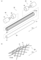
- FIG. 1(a) is an exploded perspective view of a fluid pressure actuator according to one embodiment
- FIG. 1(b) is an enlarged perspective view showing a part of a sleeve in which a restraining member is integrated by being woven into the sleeve.
- 2A and 2B are development views of a sleeve used in the hydraulic actuator
- FIG. 2A is a diagram showing a state before the hydraulic actuator is extended
- FIG. 2B is a state in which the hydraulic actuator is stretched.
- FIG. 3A and 3B are cross-sectional views along the axial direction of the fluid pressure actuator
- FIG. 3A is a cross-sectional view showing the state before the fluid pressure actuator is bent by the fluid pressure
- FIG. 10 is a cross-sectional view showing a state after applying fluid pressure to the fluid pressure actuator to bend it.
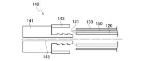
- FIG. 4 is an enlarged exploded cross-sectional view of a state before caulking in the vicinity of a sealing member of a fluid pressure actuator according to a modification.
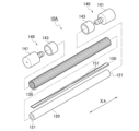
- FIG. 5 is an exploded perspective view of a fluid pressure actuator according to a modification.
- FIG. 1(a) is an exploded perspective view of a fluid pressure actuator according to one embodiment.
- FIG. 1(b) is an enlarged perspective view showing an enlarged part of the sleeve in which the restraint member is woven into the sleeve and integrated.
- the fluid pressure actuator 10 is made by weaving a tube 20 that expands and contracts with the pressure of a fluid and fiber cords 31 that are oriented in a predetermined direction (predetermined weaving angle) ⁇ 1. and a pair of sealing members 40 for sealing both ends 21 of the tube 20 in the axial direction XA.
- the fluid pressure actuator 10 of the embodiment As a basic characteristic of the fluid pressure actuator 10 of the embodiment, when the fluid pressure inside the tube 20 is increased, the tension of the fiber cords 31 forming the sleeve 30 restricts radial expansion of the fluid pressure actuator 10 . Extends in the axial direction XA. Then, when the fluid pressure in the tube 20 is lowered, the dimension in the axial direction XA is restored. Such a change in shape allows the fluid pressure actuator 10 to function as an actuator.
- Such a fluid pressure actuator 10 is a so-called McKibben type fluid pressure actuator, and can be suitably used for artificial muscles.
- the pair of sealing members 40 may be provided with a connection portion (not shown) or the like that is connected to a member or the like to be connected.
- the extension in the axial direction XA is restricted (restricted or A restraining member 50 (which may be called a restriction, hereinafter the same) is provided in a part of the fluid pressure actuator 10 in the circumferential direction.
- a restraining member 50 which may be called a restriction, hereinafter the same
- the fluid pressure actuator 10 can bend (curl) in an orthogonal direction orthogonal to the axial direction XA, that is, in the axial direction XA.
- the fluid used to drive the fluid pressure actuator 10 may be gas such as air, or liquid such as water or mineral oil.
- the hydraulic actuator 10 can have a high durability that can withstand hydraulic actuation in which high pressure is applied to the tube 20 and the sleeve 30 . Further, when a tube having a thickness or a material capable of being driven by a gas such as air at a low pressure is used as the tube 20 of the fluid pressure actuator 10, flexibility of the fluid pressure actuator 10 is ensured.
- the fluid pressure actuator 10 having such a tube 20 can be suitably used for gently grasping a soft or light, easily deformable object to be manipulated.
- each sealing member 40 includes a sealing member body 41 and a crimping member 43 .
- the sealing member main body 41 seals the end 21 of the tube 20 in the axial direction XA.
- the crimping member 43 crimps the tube 20 and the sleeve 30 together with the sealing member main body 41 .
- an indentation which is a mark resulting from caulking of the caulking member 43 by a jig, may be formed.
- the sealing member main body 41 of at least one sealing member 40 of the pair of sealing members 40 is provided with a connection port to which a hose (pipe line) connected to the driving pressure source of the fluid pressure actuator 10 is attached. .
- the fluid pressure inside the tube 20 is controlled by the fluid that flows into and out of the fluid pressure actuator 10 through the fluid passage 45 communicating with this connection port, and the tube 20 of the fluid pressure actuator 10 expands and contracts.
- a driving pressure source for the fluid pressure actuator 10 is, for example, a gas or liquid compressor.
- the fluid pressure actuator 10 is composed of the tube 20, the sleeve 30, the pair of sealing members 40, and the restraining member 50, as described above. be.
- the tube 20 is a cylindrical body that expands or contracts due to fluid pressure.
- the tube 20 is made of an elastic material such as butyl rubber because it is repeatedly expanded and contracted by the fluid.
- the elastic material is at least one selected from the group consisting of NBR (nitrile rubber) having high oil resistance, hydrogenated NBR, chloroprene rubber, and epichlorohydrin rubber. is preferred.
- FIG. 2 is an exploded view of the sleeve 30 used in the fluid pressure actuator 10.
- FIG. 2(a) is an exploded view showing a state before the hydraulic actuator 10 expands.
- FIG. 2(b) is a developed view showing a state in which the fluid pressure actuator 10 is extended.
- the sleeve 30 is cylindrical and covers the outer peripheral surface of the tube 20 in the fluid pressure actuator 10 .
- the sleeve 30 is oriented in a predetermined direction (predetermined braiding angle) ⁇ 1 with respect to the axial direction (axial direction of the fluid pressure actuator 10) XA of the tube 20 before the internal fluid pressure is increased.
- It is a stretchable structure in which the fiber cords 31 are woven.
- the fiber cords 31 are woven in a structure in which oriented fiber cords 31 intersect to repeat rhombic shapes. By having such a shape, the sleeve 30 is pantograph-deformed as shown in FIGS.
- the sleeve 30 crimped to the sealing member 40 together with the tube 20 has a braid angle of 54.7 deg. when the fluid pressure actuator 10 is driven. Drive to converge. Therefore, when the braid angle of the fluid pressure actuator 10 before driving is smaller than 54.7 degrees, the fluid pressure actuator 10 contracts in the axial direction. When the braid angle is greater than 54.7 degrees, the fluid pressure actuator 10 extends in the axial direction.
- the orientation of the fiber cords 31 of the sleeve 30 before expansion and contraction is relative to the axial direction XA of the fluid pressure actuator 10 before pressurization. It is knitted so as to form a predetermined knitting angle ⁇ 1 greater than 54.7 degrees.
- the orientation of the fiber cords 31 that regulate deformation of the tube 20 due to changes in the internal fluid pressure is such that the fluid pressure actuator 10 extends in a predetermined direction (predetermined braiding angle) ⁇ 1 when the tube 20 expands.
- the fiber cord 31 is woven into the sleeve 30 such that the braiding angle ⁇ 1 is 60 degrees to 80 degrees.
- the fiber cord 31 constituting the sleeve 30 it is preferable to use a fiber cord of aromatic polyamide (aramid fiber) or polyethylene terephthalate (PET).
- the cord is not limited to this type of fiber cord, and may be, for example, a cord of high-strength fiber such as PBO fiber (polyparaphenylenebenzobisoxazole).
- the restraint member 50 is provided in a part of the tube 20 in the circumferential direction from one end side to the other end side in the axial direction XA. Both ends of the restraining member 50 are crimped to the sealing member 40 together with the tube 20 and the sleeve 30 .
- the restraint member 50 is a member having a tensile strength capable of resisting the expansion drive of the fluid pressure actuator 10 .
- the restraining member 50 is composed of a restraining fiber cord 51 that is woven and integrated with the sleeve 30, as shown in FIG. 1(b).
- the restraining fiber cord 51 included in the restraining member 50 is crimped to the sealing member 40 while being integrated with the sleeve 30 .
- the constraining fiber cords 51 are woven into the sleeve 30 so as to intersect the fiber cords 31 at positions where the fiber cords 31 of the sleeve 30 intersect with each other while being integrated with the sleeve 30 .
- the restraining fiber cord 51 is not particularly limited as long as it is selected according to the size of the fluid pressure actuator 10 and the required generated force. In other words, the restraining fiber cord 51 only needs to have a tensile strength that can resist the extension drive of the fluid pressure actuator 10 . Also, the material of the restraining fiber cord 51 is not particularly limited. Typically, the material of the constraining fiber cord 51 may be selected from among fiber cords that can be used for the fiber cord 31 constituting the sleeve 30 in consideration of the desired tensile strength and the like. That is, the restraining fiber cord 51 may be a fiber cord made of the same material as the fiber cord 31, or a fiber cord different from the fiber cord 31 may be selected.
- the sealing member 40 seals the end portion 21 of the tube 20 in the axial direction XA of the fluid pressure actuator 10 .
- the sealing member 40 is composed of a sealing member main body 41 and a caulking member 43 .
- the sealing member body 41 is inserted through the tubular tube 20 .
- the sealing member main body 41 has a head portion larger than the inner diameter of the tube 20 and a body portion having an outer diameter that allows insertion into the inner diameter of the tube 20 .
- the body portion is inserted through the tube 20 .
- a metal such as stainless steel can be suitably used as the sealing member main body 41, but the material is not limited to such a metal.
- a hard plastic material or the like may be used as the sealing member main body 41 .
- the crimping member 43 crimps the tube 20 inserted through the sealing member main body 41 , the sleeve 30 covering the outer peripheral surface of the tube 20 , and the binding member 50 woven into and integrated with the sleeve together with the sealing member main body 41 .
- the caulking member 43 is provided on the outer periphery of the portions of the tube 20, the sleeve 30, and the restraining member 50 that are inserted into the sealing member main body 41, and connects these members 20, 30, and 50 to the sealing member main body. Crimp to 41.
- the caulking member 43 metals such as aluminum alloy, brass, and iron can be used.
- an indentation may be formed in the crimping member 43 .
- the sealing member 40 may include a locking ring (not shown) that locks the sleeve 30 and the restraining member 50 to the sealing member main body 41 .
- the sleeve 30 and the restraining member 50 may be folded radially outward via the locking ring.
- the shape of the locking ring may be a shape that can be engaged with the sealing member main body 41 .
- materials such as metals and hard plastic materials similar to those of the sealing member main body 41, natural fibers (threads of natural fibers), rubber (for example, O-rings), and the like can be used. can.
- FIG. 3 is a cross-sectional view along the axial direction XA of the fluid pressure actuator. Specifically, FIG. 3A is a cross-sectional view showing a state before the fluid pressure actuator is bent by the fluid pressure. FIG. 3(b) is a cross-sectional view showing a state after the fluid pressure actuator is bent by applying fluid pressure.
- the tube 20 is inserted through the trunk portion of the sealing member main body 41 .
- the tube 20 , the sleeve 30 covering the outer peripheral surface of the tube 20 , and the restraining member 50 woven into the sleeve 30 are crimped to the sealing member main body 41 by a crimping member 43 .
- the restraint member 50 is provided only partially in the circumferential direction of the tube 20 (see FIG. 1, for example).
- the restraining member 50 is provided from one end side to the other end side in the axial direction XA of the tube 20 and the sleeve 30 .
- the restraint member 50 may be provided from the sealing member 40 on one end side of the tube 20 in the axial direction XA to the sealing member 40 on the other end side. good.
- the restraining member 50 does not necessarily have to be provided completely from the sealing member 40 on the one end side to the sealing member 40 on the other end side. Any one of the sealing members 40 (particularly, the side of the sealing member 40 that is likely to become a free end when bent) does not need to have the binding member 50 extending therefrom. In such a case, for example, the end of the restraining member 50 that does not extend to the sealing member 40 may be fixed to, for example, a part of the tube 20 or the sleeve 30 on the other end.
- the crimping member 43 is larger than the outer diameter of the trunk portion of the sealing member body 41, and is crimped by a jig after being inserted through the trunk portion.
- the crimping member 43 crimps the tube 20 and the sleeve 30 together with the sealing member main body 41 .
- FIGS. 3A and 3B are explanatory diagrams of the behavior of the fluid pressure actuator 10.
- FIG. The fluid pressure actuator 10 shown in FIGS. 3(a) and 3(b) has a fixed end to which the sealing member 40 on the left side of the drawing is fixed.
- a sealing member 40 on the other end side, which is arranged on the right side of the fluid pressure actuator 10 in the drawing, is a free end in a freely movable state.
- the restricting member 50 extends in a part of the circumferential direction (upper side in FIGS. 3A and 3B) where the restricting member 50 of the tube 20 whose outer peripheral surface is covered with the sleeve 30 is arranged. Therefore, the elongation of the tube 20 is inhibited.
- the tube 20 expands at a portion facing a portion of the tube 20 in the circumferential direction (lower side in FIGS. 3(a) and 3(b)).
- the length of the side on which the restraining member 50 is arranged (the upper side in FIGS. 3(a) and 3(b)) is , 3(b) below).
- the free end side (right side in FIG. 3(b)) curves toward the side where the restraining member 50 is arranged (upper side in FIG. 3(b)).
- the fluid pressure actuator 10 has the following features.
- the restraining member 50 is composed of the restraining fiber cord 51 as in the fluid pressure actuator 10 of the present embodiment
- the deformable parts of the fluid pressure actuator 10 such as the tube 20, the sleeve 30, and the restraining member 50 are plastically deformed. Constructed of difficult materials. For this reason, the fluid pressure actuator 10 has flexibility such that it does not undergo plastic deformation even when it comes into contact with another rigid body during operation.
- members with high rigidity are not used in the portions where the fluid pressure actuator 10 is deformed, such as the tube 20, the sleeve 30, and the restraining member 50, soft or light and easily deformable operation targets can be gently grasped without being destroyed or deformed. It works even better.
- the sleeve 30 and the restraint member 50 exhibit integral behavior. become.
- the configuration in which the restraining member 50 is integrated with the sleeve 30 facilitates control of the curved state of the fluid pressure actuator 10 .
- the restraining member 50 is knitted and integrated with the sleeve 30 .
- the configuration of the restraining member is not limited to this configuration.
- the restraining member and the sleeve may be separate bodies.
- the restraining member 150 and the sleeve 130 are separate, the restraining member 150 is arranged between the sleeve 130 and the tube 120 as shown in FIG.
- FIG. 4 is an enlarged exploded cross-sectional view of a state before caulking in the vicinity of the sealing member 140 of the fluid pressure actuator according to the modification in which the restraining member 150 and the sleeve 130 are separately formed.
- the tube 120 is inserted through the body of a sealing member 140 having a sealing member main body 141 in which a fluid passage 145 is formed and a crimping member 143 .
- the crimping member 143 crimps the tube 120 , the sleeve 130 and the restraining member 150 together with the sealing member main body 141 .
- a composite tape material in which the restraining fiber cord 151 and a thermoplastic resin tape or the like are integrated may be used as the restraining member 150 .
- the binding member 150 which is a composite tape material, is provided from one end side to the other end side of the tube 120 in the axial direction XA.
- the binding fiber cord 151 of the composite tape material is also provided from one end side to the other end side in the axial direction XA of the tube 120 .
- the constraining fiber cord 151 may be sandwiched and integrated between the thermoplastic resin tapes, and a part of the constraining fiber cord 151 may be in contact with or embedded in the thermoplastic resin tape.
- the material of the constraining fiber cord 151 is selected from fiber cords that can be used for the fiber cord 31 in consideration of the desired tensile strength and the like. I wish I could.
- thermoplastic resin tape Materials constituting the thermoplastic resin tape are not particularly limited, but examples include polypropylene (PP), high density polyethylene (HDPE), medium density polyethylene (MDPE), low density polyethylene (LDPE), polystyrene (PS), polyethylene terephthalate (PETP), polybutylene terephthalate (PBTP), polyvinylidene fluoride (PVDF), polyamide 6 (PA6), polyamide 66 (PA66), and the like.
- PP polypropylene
- HDPE high density polyethylene
- MDPE medium density polyethylene
- LDPE low density polyethylene
- PS polystyrene
- PETP polyethylene terephthalate
- PBTP polybutylene terephthalate
- PVDF polyvinylidene fluoride
- PA6 polyamide 6
- PA66 polyamide 66
- the binding member 150 is a composite tape material in which the binding fiber cords 151 and a thermoplastic resin tape or the like are integrated, as shown in FIG. They may be provided from one end side to the other end side in the direction XA and may be arranged so as to cross each other.
- the restraining member may include a plurality of intersecting fiber cords for restraining, and the plurality of fiber cords for restraining 51 may be woven into the sleeve 30 so as to intersect each other.
- the circumferential part of the tubes 20 and 120 on which the restraining members 50 and 150 are arranged refers to the circumferential length in the circumferential direction. It may be in the range of 1/3 or less.
- the restraint member includes a plurality of restraining fiber cords 51 crossing each other, deformation of the fluid pressure actuator 10 that bends so that tension of only some of the restraining fiber cords 51 increases is suppressed, and the fluid pressure actuator 10 is restrained. It can be curved along a predetermined direction in which member 50 extends.
- the restraining member 150 that is separate from the sleeve 130 can be used.
- a leaf spring that is flat or curved to follow the cross-sectional shape of the tube 120 may be used. Even when a leaf spring is used as the restraint member 150, the restraint member 150 is provided in a part of the tube 120 in the circumferential direction.
- a leaf spring is used as the restraining member 150, by arranging the restraining member 150 between the sleeve 130 and the tube 120, it is possible to obtain a bending fluid pressure actuator with increased rigidity.
- the dimensions of the leaf spring are not particularly limited as long as they are selected according to the size of the fluid pressure actuator, the required generated force, and the like.
- the material of the leaf spring is also not particularly limited, but typically, any material such as metal such as stainless steel that is easy to bend and has high resistance to compression may be used.
- the restraint member 150 may be formed of a carbon fiber reinforced plastic (CFRP) sheet or the like. Since CFRP is less likely to be plastically deformed than metal, even when used as the restraining member 150, the fluid pressure actuator easily returns to its original straight state after bending.
- CFRP carbon fiber reinforced plastic
- the width of the leaf spring as the restraint member 150 is not particularly limited, but if the outer diameter of the tube 120 is used as a reference, it may be approximately half the outer diameter.
- the outer diameter of the tube 120 is 11 mm
- the length of the tube 120 before expansion is 185 mm
- the width of the restraint member 150 (leaf spring) is 6 mm
- the thickness is about 0.5 mm.
- the restraint members 50 and 150 are provided on a part of the tubes 20 and 120 in the circumferential direction (1/3 or less of the circumferential length).
- the restraining member may be provided in a range of about half (half the circumference) of the tubes 20 and 120 in the circumferential direction.
- the restraining members 50, 150 are provided from one end side to the other end side in the axial direction XA of the tubes 20, 120 and sleeves 30, 130.
- the restraining members 50 and 150 do not necessarily have to be provided from one end to the other end in the axial direction XA as long as they are provided over substantially the entire region in the axial direction XA.
Landscapes
- Engineering & Computer Science (AREA)
- Mechanical Engineering (AREA)
- Chemical & Material Sciences (AREA)
- Analytical Chemistry (AREA)
- Physics & Mathematics (AREA)
- Fluid Mechanics (AREA)
- General Engineering & Computer Science (AREA)
- Robotics (AREA)
- Actuator (AREA)
Abstract
Description
図1(a)は、一実施形態に係る流体圧アクチュエータの分解斜視図である。図1(b)は、拘束部材がスリーブに編み込まれて一体化しているスリーブの一部分を拡大した拡大斜視図である。
図1(a)に示すように、流体圧アクチュエータ10は、上述したように、チューブ20、スリーブ30、一対の封止部材40、及び拘束部材50によって構成される。
図3は、流体圧アクチュエータの軸方向XAに沿った断面図である。具体的に、図3(a)は、流体圧アクチュエータが流体圧によって湾曲する前の状態を示す断面図である。図3(b)は、流体圧アクチュエータに流体圧をかけて湾曲させた後の状態を示す断面図である。
図3(a)、3(b)は、流体圧アクチュエータ10の挙動の説明図である。図3(a)、3(b)に示されている流体圧アクチュエータ10は、図中左側に配置された一端側の封止部材40側が固定された固定端である。そして、流体圧アクチュエータ10の図中右側に配置された他端側の封止部材40が自由に移動できる状態にある自由端である。
流体圧アクチュエータ10は、以下のような特徴を有している。
・力の制御が容易(圧力に発生力が比例する)
・構造がシンプル
・表面をコートすることによって、操作対象に直接触れることも可能
また、ロボットハンド等に本実施形態の流体圧アクチュエータ10を用いた場合、流体圧アクチュエータ10では、チューブ20の伸縮を拘束する拘束部材50が湾曲状態の内側に位置することになる。このため、湾曲過程で、湾曲内側のスリーブ30およびチューブ20が伸縮しない。このため、流体圧アクチュエータ10を用いたロボットハンド等では、湾曲過程で操作対象と流体圧アクチュエータ10との接触点がチューブ20の伸縮によって滑ることがない。そして、軟らかい或いは軽くて変形しやすい操作対象を破壊、変形させることなく優しく掴み得る。
以上、実施形態に沿って本発明の内容を説明したが、本発明はこれらの記載に限定されるものではなく、種々の変形及び改良が可能であることは、当業者には自明である。
Claims (5)
- 流体の圧力によって膨張および収縮するチューブと、
所定方向に配向された繊維コードを編み込んだ伸縮性を有する構造体であり前記チューブの外周面を覆うスリーブと、
前記チューブの軸方向における端部を封止する封止部材と、を備え、
前記スリーブの前記繊維コードが配向する前記所定方向が、前記チューブが膨張すると伸長する配向にされており、
前記チューブの周方向の一部に前記軸方向における一端側から他端側に亘って設けられ、前記チューブの前記周方向の一部における前記軸方向に沿った伸長を拘束する拘束部材をさらに備える流体圧アクチュエータ。 - 記拘束部材は、前記スリーブに編み込まれて一体化された請求項1に記載の流体圧アクチュエータ。
- 記拘束部材は、前記スリーブと前記チューブとの間に配置された請求項1に記載の流体圧アクチュエータ。
- 前記拘束部材が拘束用繊維コードを含む、請求項2または3に記載の流体圧アクチュエータ。
- 前記拘束部材が互いに交差する複数の前記拘束用繊維コードを含む請求項4に記載の流体圧アクチュエータ。
Priority Applications (3)
| Application Number | Priority Date | Filing Date | Title |
|---|---|---|---|
| CN202280081397.4A CN118355198A (zh) | 2021-12-17 | 2022-10-11 | 流体压驱动器 |
| EP22906982.8A EP4450829A4 (en) | 2021-12-17 | 2022-10-11 | Hydraulic actuator |
| US18/718,929 US20250052261A1 (en) | 2021-12-17 | 2022-10-11 | Hydraulic actuator |
Applications Claiming Priority (2)
| Application Number | Priority Date | Filing Date | Title |
|---|---|---|---|
| JP2021-205532 | 2021-12-17 | ||
| JP2021205532A JP7736554B2 (ja) | 2021-12-17 | 2021-12-17 | 流体圧アクチュエータ |
Publications (1)
| Publication Number | Publication Date |
|---|---|
| WO2023112447A1 true WO2023112447A1 (ja) | 2023-06-22 |
Family
ID=86774390
Family Applications (1)
| Application Number | Title | Priority Date | Filing Date |
|---|---|---|---|
| PCT/JP2022/037853 Ceased WO2023112447A1 (ja) | 2021-12-17 | 2022-10-11 | 流体圧アクチュエータ |
Country Status (5)
| Country | Link |
|---|---|
| US (1) | US20250052261A1 (ja) |
| EP (1) | EP4450829A4 (ja) |
| JP (1) | JP7736554B2 (ja) |
| CN (1) | CN118355198A (ja) |
| WO (1) | WO2023112447A1 (ja) |
Families Citing this family (1)
| Publication number | Priority date | Publication date | Assignee | Title |
|---|---|---|---|---|
| CN121716031A (zh) * | 2026-02-24 | 2026-03-24 | 上海今日芯动科技有限公司 | 三维约束结构及系统、仿生机器人部件及形变引导方法 |
Citations (9)
| Publication number | Priority date | Publication date | Assignee | Title |
|---|---|---|---|---|
| JPH03113104A (ja) * | 1989-09-25 | 1991-05-14 | Bridgestone Corp | 湾曲可能なアクチュエータ |
| JPH06147202A (ja) * | 1992-11-02 | 1994-05-27 | Ckd Corp | 形状可変アクチュエータ |
| US20050081711A1 (en) * | 2002-03-04 | 2005-04-21 | Laszlo Kerekes | Pneumatic actuator |
| JP2015180829A (ja) * | 2014-03-06 | 2015-10-15 | 株式会社リコー | 流体駆動型アクチュエータ、その製造方法、及びその駆動方法、駆動装置、並びに関節構造 |
| JP2017046754A (ja) * | 2015-08-31 | 2017-03-09 | ダイヤ工業株式会社 | アクチュエータ及び身体支援装置 |
| JP2018189169A (ja) * | 2017-05-08 | 2018-11-29 | 国立大学法人東京工業大学 | アクチュエータおよび移動体 |
| JP2019090531A (ja) * | 2017-11-16 | 2019-06-13 | ヴァラン | 可変ジオメトリおよび定容積の膨張可能なチューブ、ロボットアームおよびロボット |
| JP2019120373A (ja) * | 2018-01-10 | 2019-07-22 | 興国インテック株式会社 | アクチュエータ |
| JP2021088999A (ja) | 2019-12-02 | 2021-06-10 | 株式会社ブリヂストン | 流体圧アクチュエータ |
Family Cites Families (2)
| Publication number | Priority date | Publication date | Assignee | Title |
|---|---|---|---|---|
| JP2007068794A (ja) * | 2005-09-07 | 2007-03-22 | Okayama Univ | 流体アクチュエータ、流体アクチュエータの製造方法、流体アクチュエータを備えた筋力補助装置、及び流体アクチュエータで構成した拘束具 |
| US10363670B1 (en) * | 2015-11-04 | 2019-07-30 | Ryan Gundling | Devices, systems, and methods for dynamic bending of inflatable structures |
-
2021
- 2021-12-17 JP JP2021205532A patent/JP7736554B2/ja active Active
-
2022
- 2022-10-11 EP EP22906982.8A patent/EP4450829A4/en active Pending
- 2022-10-11 WO PCT/JP2022/037853 patent/WO2023112447A1/ja not_active Ceased
- 2022-10-11 US US18/718,929 patent/US20250052261A1/en active Pending
- 2022-10-11 CN CN202280081397.4A patent/CN118355198A/zh active Pending
Patent Citations (9)
| Publication number | Priority date | Publication date | Assignee | Title |
|---|---|---|---|---|
| JPH03113104A (ja) * | 1989-09-25 | 1991-05-14 | Bridgestone Corp | 湾曲可能なアクチュエータ |
| JPH06147202A (ja) * | 1992-11-02 | 1994-05-27 | Ckd Corp | 形状可変アクチュエータ |
| US20050081711A1 (en) * | 2002-03-04 | 2005-04-21 | Laszlo Kerekes | Pneumatic actuator |
| JP2015180829A (ja) * | 2014-03-06 | 2015-10-15 | 株式会社リコー | 流体駆動型アクチュエータ、その製造方法、及びその駆動方法、駆動装置、並びに関節構造 |
| JP2017046754A (ja) * | 2015-08-31 | 2017-03-09 | ダイヤ工業株式会社 | アクチュエータ及び身体支援装置 |
| JP2018189169A (ja) * | 2017-05-08 | 2018-11-29 | 国立大学法人東京工業大学 | アクチュエータおよび移動体 |
| JP2019090531A (ja) * | 2017-11-16 | 2019-06-13 | ヴァラン | 可変ジオメトリおよび定容積の膨張可能なチューブ、ロボットアームおよびロボット |
| JP2019120373A (ja) * | 2018-01-10 | 2019-07-22 | 興国インテック株式会社 | アクチュエータ |
| JP2021088999A (ja) | 2019-12-02 | 2021-06-10 | 株式会社ブリヂストン | 流体圧アクチュエータ |
Non-Patent Citations (1)
| Title |
|---|
| See also references of EP4450829A4 |
Also Published As
| Publication number | Publication date |
|---|---|
| US20250052261A1 (en) | 2025-02-13 |
| EP4450829A4 (en) | 2025-03-26 |
| EP4450829A1 (en) | 2024-10-23 |
| CN118355198A (zh) | 2024-07-16 |
| JP7736554B2 (ja) | 2025-09-09 |
| JP2023090537A (ja) | 2023-06-29 |
Similar Documents
| Publication | Publication Date | Title |
|---|---|---|
| JP2021088999A (ja) | 流体圧アクチュエータ | |
| JPH03113104A (ja) | 湾曲可能なアクチュエータ | |
| US20190203740A1 (en) | Hydraulic actuator | |
| WO2023112447A1 (ja) | 流体圧アクチュエータ | |
| JP7349338B2 (ja) | 流体圧アクチュエータ | |
| WO2023171111A1 (ja) | ロボットハンド | |
| JP7715613B2 (ja) | 流体圧アクチュエータ | |
| JP7743296B2 (ja) | 把持装置 | |
| US20250326138A1 (en) | Fluid pressure actuator with cover | |
| EP4491884A1 (en) | Hydraulic actuator | |
| JP7717597B2 (ja) | 流体圧アクチュエータ | |
| WO2020129743A1 (ja) | 流体圧アクチュエータ | |
| JP2023090572A (ja) | 流体圧アクチュエータおよびロボットハンド | |
| EP4450832A1 (en) | Gripping device | |
| JP2023090524A (ja) | 流体圧アクチュエータ | |
| JP7611808B2 (ja) | 把持装置 | |
| JP2024084596A (ja) | 流体圧アクチュエータ | |
| WO2024053292A1 (ja) | ロボットハンド | |
| JP2023090574A (ja) | 流体圧アクチュエータおよびロボット | |
| WO2025126569A1 (ja) | 流体圧アクチュエータ | |
| WO2025126869A1 (ja) | 流体圧アクチュエータ | |
| JP2023091136A (ja) | 把持装置 | |
| WO2023171113A1 (ja) | ロボットハンド | |
| JP2021088997A (ja) | 流体圧アクチュエータ | |
| CN118355197A (zh) | 流体压驱动器 |
Legal Events
| Date | Code | Title | Description |
|---|---|---|---|
| 121 | Ep: the epo has been informed by wipo that ep was designated in this application |
Ref document number: 22906982 Country of ref document: EP Kind code of ref document: A1 |
|
| WWE | Wipo information: entry into national phase |
Ref document number: 202280081397.4 Country of ref document: CN |
|
| WWE | Wipo information: entry into national phase |
Ref document number: 18718929 Country of ref document: US |
|
| WWE | Wipo information: entry into national phase |
Ref document number: 2022906982 Country of ref document: EP |
|
| NENP | Non-entry into the national phase |
Ref country code: DE |
|
| ENP | Entry into the national phase |
Ref document number: 2022906982 Country of ref document: EP Effective date: 20240717 |