WO2023112458A1 - 把持装置 - Google Patents
把持装置 Download PDFInfo
- Publication number
- WO2023112458A1 WO2023112458A1 PCT/JP2022/038442 JP2022038442W WO2023112458A1 WO 2023112458 A1 WO2023112458 A1 WO 2023112458A1 JP 2022038442 W JP2022038442 W JP 2022038442W WO 2023112458 A1 WO2023112458 A1 WO 2023112458A1
- Authority
- WO
- WIPO (PCT)
- Prior art keywords
- fluid pressure
- gripping device
- actuator
- actuators
- pressure actuator
- Prior art date
- Legal status (The legal status is an assumption and is not a legal conclusion. Google has not performed a legal analysis and makes no representation as to the accuracy of the status listed.)
- Ceased
Links
Images





Classifications
-
- B—PERFORMING OPERATIONS; TRANSPORTING
- B25—HAND TOOLS; PORTABLE POWER-DRIVEN TOOLS; MANIPULATORS
- B25J—MANIPULATORS; CHAMBERS PROVIDED WITH MANIPULATION DEVICES
- B25J15/00—Gripping heads and other end effectors
- B25J15/0023—Gripper surfaces directly activated by a fluid
-
- B—PERFORMING OPERATIONS; TRANSPORTING
- B25—HAND TOOLS; PORTABLE POWER-DRIVEN TOOLS; MANIPULATORS
- B25J—MANIPULATORS; CHAMBERS PROVIDED WITH MANIPULATION DEVICES
- B25J15/00—Gripping heads and other end effectors
- B25J15/08—Gripping heads and other end effectors having finger members
- B25J15/10—Gripping heads and other end effectors having finger members with three or more finger members
-
- B—PERFORMING OPERATIONS; TRANSPORTING
- B25—HAND TOOLS; PORTABLE POWER-DRIVEN TOOLS; MANIPULATORS
- B25J—MANIPULATORS; CHAMBERS PROVIDED WITH MANIPULATION DEVICES
- B25J15/00—Gripping heads and other end effectors
- B25J15/08—Gripping heads and other end effectors having finger members
- B25J15/12—Gripping heads and other end effectors having finger members with flexible finger members
-
- B—PERFORMING OPERATIONS; TRANSPORTING
- B25—HAND TOOLS; PORTABLE POWER-DRIVEN TOOLS; MANIPULATORS
- B25J—MANIPULATORS; CHAMBERS PROVIDED WITH MANIPULATION DEVICES
- B25J9/00—Program-controlled manipulators
- B25J9/10—Program-controlled manipulators characterised by positioning means for manipulator elements
- B25J9/14—Program-controlled manipulators characterised by positioning means for manipulator elements fluid
- B25J9/142—Program-controlled manipulators characterised by positioning means for manipulator elements fluid comprising inflatable bodies
-
- F—MECHANICAL ENGINEERING; LIGHTING; HEATING; WEAPONS; BLASTING
- F15—FLUID-PRESSURE ACTUATORS; HYDRAULICS OR PNEUMATICS IN GENERAL
- F15B—SYSTEMS ACTING BY MEANS OF FLUIDS IN GENERAL; FLUID-PRESSURE ACTUATORS, e.g. SERVOMOTORS; DETAILS OF FLUID-PRESSURE SYSTEMS, NOT OTHERWISE PROVIDED FOR
- F15B15/00—Fluid-actuated devices for displacing a member from one position to another; Gearing associated therewith
- F15B15/08—Characterised by the construction of the motor unit
- F15B15/10—Characterised by the construction of the motor unit the motor being of diaphragm type
Definitions
- the present disclosure relates to a grasping device using a hydraulic actuator that bends (curls) when contracted.
- McKibben type a structure having a rubber tube that expands and contracts by air pressure and a sleeve that covers the outer peripheral surface of the tube. It is
- Patent Literature 1 discloses a gripping device that grips an object (which may be called a work) by using a plurality of such fluid pressure actuators.
- the gripping device using the fluid pressure actuator as described above has the following problems. Specifically, depending on the shape of the object, the object tends to fall from the tip of the fluid pressure actuator that is curled.
- the following disclosure has been made in view of such circumstances, and aims to provide a grasping device that can more reliably grasp an object while using a fluid pressure actuator that bends (curls) when contracted. .
- One aspect of the present disclosure is a gripping device (eg, gripping device 1) using a plurality of fluid pressure actuators (fluid pressure actuators 10) that bend when contracted, wherein the fluid pressure actuators are soft actuators, and the tube and a sleeve (sleeve 120) covering the outer peripheral surface of the gripping device, and in a bottom view of the gripping device, when each of the fluid pressure actuators contracts, the tip portion (tip portion 300) of each of the fluid pressure actuators Overlap actuator and tip.
- fluid pressure actuators fluid pressure actuators
- FIG. 1A and 1B are a schematic perspective view of a gripping device 1 and a schematic front view of a robot arm 2 including the gripping device 1 according to this embodiment.
- 2(a) and 2(b) are a schematic side view and a schematic bottom view of the gripping device 1.
- FIG. FIG. 3 is a side view of the hydraulic actuator 10.
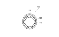
- FIG. FIG. 4 is a cross-sectional view of the actuator main body 100 along the radial direction DR .
- FIG. 5 is an explanatory diagram of the behavior of the fluid pressure actuator 10.
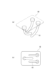
- FIG. 6(a) and (b) are a schematic side view and a schematic bottom view of the gripping device 1A.
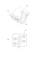
- 7(a) and (b) are a schematic side view and a schematic bottom view of the gripping device 1B.
- 8(a) and (b) are a schematic side view and a schematic bottom view of the gripping device 1C.
- 9(a) and (b) are a schematic side view and a schematic bottom view
- FIGS. 1A and 1B are a schematic perspective view of a gripping device 1 according to the present embodiment and a schematic front view of a robot arm 2 including the gripping device 1.
- FIG. 2(a) and 2(b) are a schematic side view and a schematic bottom view of the gripping device 1.
- FIG. 1 and 2 are schematic diagrams, and the shape of the fluid pressure actuator 10 and the like are shown in a simplified manner.
- the gripping device 1 uses a plurality of fluid pressure actuators 10 that bend (curl) when contracted.
- the gripping device 1 can grip an object W (which may be called a work) using a plurality of fluid pressure actuators 10 (flexible and flexible soft actuators).
- the grasping device 1 may be used as a robot hand or the like, and may be included in the robot arm 2 .
- two fluid pressure actuators are provided facing each other. Specifically, by contracting the two fluid pressure actuators 10, the two fluid pressure actuators 10 can grasp the object W, in other words, hold the object W. 1 and 2 show the state in which the fluid pressure actuator 10 is bent.
- the fluid pressure actuator 10 is attached to a mounting portion 30 provided on the mounting base 20.
- the mounting pedestal 20 may be supported by an arm, support, or the like (not shown).
- the distal end portions 300 of the fluid pressure actuators overlap the other fluid pressure actuators and the distal end portions 300 when the respective fluid pressure actuators contract.
- a straight line L1 along the axial direction D AX of the fluid pressure actuator (see FIG. 3) is aligned with the other fluid pressure actuator in the bottom view of the gripping device 1. is provided so as to avoid crossing with straight line L2 along the axial direction of . That is, the distal end portion 300 of the fluid pressure actuator is provided so as not to interfere with the distal end portion 300 of the opposing fluid pressure actuator even when contracted.
- the position of the mounting portion 30, in other words, the base end portion 200 of the fluid pressure actuator is the position of the base end portion 200 of the opposing fluid pressure actuator in the axial direction DAX of the fluid pressure actuator. It is offset from the position.
- the gripping device 1 two fluid pressure actuators are provided facing each other, but the number of fluid pressure actuators constituting the gripping device is not particularly limited.
- the number of fluid pressure actuators constituting the gripping device is two or more and four or less.
- FIG. 3 is a side view of the fluid pressure actuator 10 according to this embodiment.
- FIG. 4 is a cross-sectional view of the actuator main body 100 along the radial direction DR .
- the fluid pressure actuator 10 has an actuator main body 100, a proximal end 200 and a distal end 300.
- the actuator main body 100 is composed of a tube 110 and a sleeve 120. A fluid flows into the actuator body 100 through the connection port 211a.
- the actuator main body 100 contracts in the axial direction D AX and expands in the radial direction DR due to the inflow of fluid into the tube 110 . Further, the actuator main body 100 expands in the axial direction D AX of the actuator main body 100 and contracts in the radial direction DR due to the outflow of fluid from the tube 110 . Due to such a change in shape of the actuator main body 100, the fluid pressure actuator 10 functions as an actuator.
- a restraining member 150 (which may also be referred to as regulating or limiting, hereinafter the same) that restrains compression in the axial direction D AX is used (Fig. 3 (not shown, see FIGS. 4 and 5, etc.), it is possible to bend (curl) in the orthogonal direction orthogonal to the axial direction DAX , that is, in the radial direction DR .
- the fluid used to drive the fluid pressure actuator 10 may be either a gas such as air or a liquid such as water or mineral oil. It has high durability that can withstand even
- connection port 211a is attached with a hose (pipeline) connected to a driving pressure source for the fluid pressure actuator 10, specifically, a gas or liquid compressor.
- the fluid that has flowed in through the connection port 211a passes through a passage hole (not shown) and flows into the inside of the actuator main body 100, specifically, the inside of the tube 110. As shown in FIG.
- the tube 110 is a cylindrical body that expands and contracts due to fluid pressure.
- the tube 110 is made of an elastic material such as butyl rubber because it repeatedly contracts and expands due to the fluid.
- the fluid pressure actuator 10 is hydraulically driven, it is preferably made of at least one selected from the group consisting of NBR (nitrile rubber), chloroprene rubber, and epichlorohydrin rubber, which have high oil resistance.
- the sleeve 120 is cylindrical and covers the outer peripheral surface of the tube 110.
- the sleeve 120 is an elastic structure in which fiber cords oriented in a predetermined direction are woven, and the oriented cords intersect to repeat a rhombic shape. Having such a shape, the sleeve 120 is pantograph-deformed and follows the contraction and expansion of the tube 110 while regulating it.
- the cords forming the sleeve 120 it is preferable to use aromatic polyamide (aramid fiber) or polyethylene terephthalate (PET) fiber cords.
- aromatic polyamide aramid fiber
- PET polyethylene terephthalate
- the cord is not limited to this type of fiber cord, and may be, for example, a cord of high-strength fiber such as PBO fiber (polyparaphenylenebenzobisoxazole).
- a restraining member 150 is provided between the tube 110 and the sleeve 120.
- Restraining member 150 is not compressible in the axial direction D AX and is deformable only along the radial direction D R (which may also be referred to as the deflection direction). That is, the restraining member 150 resists compression along the axial direction D AX and is deformable in the orthogonal direction (radial direction D R ) perpendicular to the axial direction D AX .
- the restraining member 150 has a characteristic of being difficult to deform along the axial direction DAX and bending along the radial direction DR . It should be noted that “deformable” may also mean “curvable” or “curlable”.
- the restraining member 150 also has a function of restraining (restricting) the expansion of the tube 110 (and the sleeve 120) outward in the radial direction DR at the position on the outer circumference of the tube 110 where the restraining member 150 is provided. ing.
- the restraining member 150 is provided inside the sleeve 120, specifically, in a space radially inside the sleeve 120, extending from one end side to the other end side in the axial direction DAX . Also, in this embodiment, the restraining member 150 is formed using a leaf spring.
- the dimensions of the leaf spring are not particularly limited as long as they are selected according to the size of the fluid pressure actuator 10 and the required generated force.
- the material of the leaf spring is also not particularly limited, but typically, any material such as metal such as stainless steel that is easy to bend and has high resistance to compression may be used.
- the restraint member 150 may be formed of a carbon fiber reinforced plastic (CFRP) sheet or the like. Since CFRP is less likely to be plastically deformed than metal, the fluid pressure actuator 10 easily returns to its original straight state after bending.
- CFRP carbon fiber reinforced plastic
- the proximal end portion 200 is located on the mounting portion 30 side of the mounting base 20 (see FIGS. 2(a) and 2(b)).
- the base end portion 200 is formed with the connection port 211a described above.
- the base end portion 200 may be provided with a mechanism for sealing one end portion of the actuator body portion 100 in the axial direction DAX .
- the tip portion 300 is located on the opposite side of the mounting portion 30 of the mounting base 20 .
- the distal end portion 300 may be provided with a mechanism for sealing the other end portion of the actuator body portion 100 in the axial direction DAX .
- the sealing mechanism of the actuator main body 100 provided at the proximal end 200 and the distal end 300 may be the same as that of the fluid pressure actuator disclosed in Japanese Patent Laid-Open No. 2021-088999, for example. Further, the distal end portion 300 may be covered with a rubber sack or the like for the purpose of preventing slipping when the object W is gripped.
- FIG. 5 is an explanatory diagram of the behavior of the fluid pressure actuator 10.
- the fluid pressure actuator 10 shown in FIG. 5 is fixed on the base end 200 side and is freely movable on the tip end 300 side. That is, the proximal end 200 side is the fixed end, and the distal end 300 side is the free end.
- the restraining member 150 made of a hard member such as a leaf spring functions like a backbone, and is located on the opposite side of the tube 110 and the sleeve 120 on the outer periphery where the restraining member 150 is provided (Fig. 5). ), the dimension of the hydraulic actuator 10 in the axial direction D AX is shortened by expanding outward in the radial direction D R , and the hydraulic actuator 10 (specifically, the actuator body 100) bends.
- the direction D1 may also be called a flexible direction.
- a mark M (see FIG. 3) may be provided to indicate the position where the restraining member 150 is provided in order to make it easier to recognize that the fluid pressure actuator 10 is bent in the direction D1.
- the restraint member 150 is provided between the rubber tube 110 and the sleeve 120, resists compression in the axial direction DAX , and is deformable along the orthogonal direction (radial direction DR ) perpendicular to the and arranged in a part of the actuator main body 100 in the circumferential direction.
- the restraining member 150 has a high compressive rigidity, so that the restraining force is reduced.
- the portion where the member 150 is arranged cannot contract.
- other portions of the actuator main body 100 try to contract, so that a force in the bending direction along the orthogonal direction (radial direction D R ) is generated and bends with the restraint member 150 as the back surface.
- 6(a) and (b) are a schematic side view and a schematic bottom view of the gripping device 1A.
- the position of the mounting portion 30, that is, the base end portion 200 (see FIG. 3) of the fluid pressure actuator is It is offset from the position of the base end 200 of the opposing hydraulic actuator in the axial direction DAX of the pressure actuator.
- the fluid pressure actuator in the bottom view of the gripping device 1, may be provided in an inclined state with the mounting base 20 as a reference. According to the gripping device 1A, by devising the flexible direction of the fluid pressure actuator, it is possible to contribute to downsizing of the device.
- Figures 7(a) and (b) are a schematic side view and a schematic bottom view of the gripping device 1B.
- 8(a) and 8(b) are a schematic side view and a schematic bottom view of the gripping device 1C.
- Three fluid pressure actuators are used in the gripping device 1B, and four fluid pressure actuators are used in the gripping device 1C.
- the number of fluid pressure actuators constituting the gripping device is not particularly limited, but each fluid pressure actuator is provided so as to face at least one of the other fluid pressure actuators.
- Figures 9(a) and (b) are a schematic side view and a schematic bottom view of the gripping device 1D.
- three fluid pressure actuators are provided so as to intersect (overlap) each other.
- the mounting portions 30, that is, the base end portions 200 of the fluid pressure actuators may be provided at equal intervals (at equal angles) on the circumference in the bottom view of the gripping device 1D.
- Proximal portion 200 may be provided on a circumference having the same radius from the center.
- each fluid pressure actuator moves to a position offset from the center of the arc forming the circumference when the fluid pressure actuator contracts. Therefore, the tip portions 300 of each hydraulic actuator can cross each other without interference.
- the object W is less likely to fall from the tip 300 of the curled fluid pressure actuator. That is, according to the gripping device described above, the object W can be gripped more reliably while using a fluid pressure actuator that bends (curls) when contracted.
- a straight line L1 along the axial direction D AX (see FIG. 3) of the fluid pressure actuator is a straight line L2 along the axial direction of the other fluid pressure actuator.
- the base end portion 200 of each fluid pressure actuator is provided on the circumference in a bottom view of the gripping device 1D. Towards a position offset from the center of the arc forming the circumference. Therefore, the distal end portions 300 of the respective fluid pressure actuators can cross each other without interfering with each other, so that the object W can be more reliably prevented from falling off.
- the restraint member 150 is used to ensure the flexibility of the fluid pressure actuator, but the flexibility of the fluid pressure actuator may be ensured by another structure. For example, by providing a flexible frame partly bellows-shaped around the fluid pressure actuator, when the fluid pressure actuator contracts, the fluid pressure actuator may be bent with the bellows portion inside. .
Landscapes
- Engineering & Computer Science (AREA)
- Mechanical Engineering (AREA)
- Robotics (AREA)
- Physics & Mathematics (AREA)
- Fluid Mechanics (AREA)
- General Engineering & Computer Science (AREA)
- Actuator (AREA)
- Manipulator (AREA)
Abstract
Description
図1(a)及び(b)は、本実施形態に係る把持装置1の概略斜視図及び把持装置1を含むロボットアーム2の概略正面図である。図2(a)及び(b)は、把持装置1の概略側面図及び概略底面図である。なお、図1及び図2は概略図であり、流体圧アクチュエータ10の形状などは、簡略化して示されている。
図3は、本実施形態に係る流体圧アクチュエータ10の側面図である。図4は、アクチュエータ本体部100の径方向DRに沿った断面図である。
図5は、流体圧アクチュエータ10の挙動の説明図である。図5に示されている流体圧アクチュエータ10は、基端部200側が固定されており、先端部300側は自由に移動できる状態である。つまり、基端部200側が固定端であり、先端部300側が自由端である。
次に、把持装置1の変更例について説明する。図6(a)及び(b)は、把持装置1Aの概略側面図及び概略底面図である。
上述した実施形態によれば、以下の作用効果が得られる。具体的には、上述した変更例を含む把持装置によれば、流体圧アクチュエータの先端部300は、流体圧アクチュエータそれぞれが収縮すると、他の流体圧アクチュエータと先端部300とオーバラップする。
以上、実施形態について説明したが、当該実施形態の記載に限定されるものではなく、種々の変形及び改良が可能であることは、当業者には自明である。
2 ロボットアーム
10 流体圧アクチュエータ
20 取付台座
30 取付部
100 アクチュエータ本体部
110 チューブ
120 スリーブ
150 拘束部材
200 基端部
211a 接続口
300 先端部
W 対象物
Claims (6)
- 収縮時に湾曲する流体圧アクチュエータを複数用いた把持装置であって、
前記流体圧アクチュエータは、ソフトアクチュエータであり、
前記把持装置の底面視において、前記流体圧アクチュエータの先端部は、前記流体圧アクチュエータそれぞれが収縮すると、他の前記流体圧アクチュエータと先端部とオーバラップする把持装置。 - 前記流体圧アクチュエータは、
流体の圧力によって膨張及び収縮する円筒状のチューブと、
所定方向に配向された繊維コードを編み込んだ伸縮性を有する構造体であり、前記チューブの外周面を覆うスリーブと
を含む請求項1に記載の把持装置。 - 前記流体圧アクチュエータのそれぞれは、前記把持装置の底面視において、前記流体圧アクチュエータの軸方向に沿った直線が、他の前記流体圧アクチュエータの軸方向に沿った直線との交差を回避するように設けられる請求項1に記載の把持装置。
- 前記流体圧アクチュエータそれぞれの基端部は、前記把持装置の底面視において、円周上に設けられ、
前記流体圧アクチュエータそれぞれの先端部は、前記流体圧アクチュエータが収縮すると、前記円周を形成する円弧の中心からオフセットした位置に向かう請求項1に記載の把持装置。 - 前記流体圧アクチュエータの本数は、2本以上、4本以下である請求項1乃至4の何れか一項に記載の把持装置。
- 前記流体圧アクチュエータは、前記スリーブの内側において、前記チューブの軸方向における一端側から他端側に亘って設けられる拘束部材を備える請求項2に記載の把持装置。
Priority Applications (3)
| Application Number | Priority Date | Filing Date | Title |
|---|---|---|---|
| US18/720,060 US20250050512A1 (en) | 2021-12-15 | 2022-10-14 | Grasping device |
| CN202280082452.1A CN118382760A (zh) | 2021-12-15 | 2022-10-14 | 把持装置 |
| EP22906993.5A EP4450832A4 (en) | 2021-12-15 | 2022-10-14 | Gripping device |
Applications Claiming Priority (2)
| Application Number | Priority Date | Filing Date | Title |
|---|---|---|---|
| JP2021203536A JP2023088662A (ja) | 2021-12-15 | 2021-12-15 | 把持装置 |
| JP2021-203536 | 2021-12-15 |
Publications (1)
| Publication Number | Publication Date |
|---|---|
| WO2023112458A1 true WO2023112458A1 (ja) | 2023-06-22 |
Family
ID=86774402
Family Applications (1)
| Application Number | Title | Priority Date | Filing Date |
|---|---|---|---|
| PCT/JP2022/038442 Ceased WO2023112458A1 (ja) | 2021-12-15 | 2022-10-14 | 把持装置 |
Country Status (5)
| Country | Link |
|---|---|
| US (1) | US20250050512A1 (ja) |
| EP (1) | EP4450832A4 (ja) |
| JP (1) | JP2023088662A (ja) |
| CN (1) | CN118382760A (ja) |
| WO (1) | WO2023112458A1 (ja) |
Citations (4)
| Publication number | Priority date | Publication date | Assignee | Title |
|---|---|---|---|---|
| JPH03130392U (ja) * | 1990-04-12 | 1991-12-27 | ||
| JP2019010713A (ja) * | 2017-06-30 | 2019-01-24 | ファナック株式会社 | ハンド制御装置、ハンド制御方法、およびハンドのシミュレーション装置 |
| WO2020072815A1 (en) * | 2018-10-03 | 2020-04-09 | Nicholas Payton | Hybrid robotic picking device |
| JP2021088999A (ja) | 2019-12-02 | 2021-06-10 | 株式会社ブリヂストン | 流体圧アクチュエータ |
Family Cites Families (2)
| Publication number | Priority date | Publication date | Assignee | Title |
|---|---|---|---|---|
| JP2008194788A (ja) * | 2007-02-14 | 2008-08-28 | Shin Meiwa Ind Co Ltd | 把持機構およびそれを備えたロボットハンド |
| WO2016029130A1 (en) * | 2014-08-22 | 2016-02-25 | President And Fellows Of Harvard College | Flexible and stretchable electronic strain-limited layer for soft actuators |
-
2021
- 2021-12-15 JP JP2021203536A patent/JP2023088662A/ja active Pending
-
2022
- 2022-10-14 WO PCT/JP2022/038442 patent/WO2023112458A1/ja not_active Ceased
- 2022-10-14 CN CN202280082452.1A patent/CN118382760A/zh active Pending
- 2022-10-14 EP EP22906993.5A patent/EP4450832A4/en not_active Withdrawn
- 2022-10-14 US US18/720,060 patent/US20250050512A1/en active Pending
Patent Citations (4)
| Publication number | Priority date | Publication date | Assignee | Title |
|---|---|---|---|---|
| JPH03130392U (ja) * | 1990-04-12 | 1991-12-27 | ||
| JP2019010713A (ja) * | 2017-06-30 | 2019-01-24 | ファナック株式会社 | ハンド制御装置、ハンド制御方法、およびハンドのシミュレーション装置 |
| WO2020072815A1 (en) * | 2018-10-03 | 2020-04-09 | Nicholas Payton | Hybrid robotic picking device |
| JP2021088999A (ja) | 2019-12-02 | 2021-06-10 | 株式会社ブリヂストン | 流体圧アクチュエータ |
Non-Patent Citations (1)
| Title |
|---|
| See also references of EP4450832A4 |
Also Published As
| Publication number | Publication date |
|---|---|
| EP4450832A4 (en) | 2025-03-12 |
| EP4450832A1 (en) | 2024-10-23 |
| JP2023088662A (ja) | 2023-06-27 |
| US20250050512A1 (en) | 2025-02-13 |
| CN118382760A (zh) | 2024-07-23 |
Similar Documents
| Publication | Publication Date | Title |
|---|---|---|
| JP2021088999A (ja) | 流体圧アクチュエータ | |
| WO2023171111A1 (ja) | ロボットハンド | |
| JP7349338B2 (ja) | 流体圧アクチュエータ | |
| WO2023119809A1 (ja) | 把持装置 | |
| JP2023088662A (ja) | 把持装置 | |
| WO2023112457A1 (ja) | 把持装置 | |
| US20250188961A1 (en) | Fluid pressure actuator | |
| US20250326138A1 (en) | Fluid pressure actuator with cover | |
| JP2023091136A (ja) | 把持装置 | |
| JP7611808B2 (ja) | 把持装置 | |
| JP2023090524A (ja) | 流体圧アクチュエータ | |
| WO2023171113A1 (ja) | ロボットハンド | |
| EP4450829A1 (en) | Hydraulic actuator | |
| JP2008194788A (ja) | 把持機構およびそれを備えたロボットハンド | |
| WO2023112448A1 (ja) | アクチュエータカバー付き保持部材及びアクチュエータカバー | |
| JP2023090574A (ja) | 流体圧アクチュエータおよびロボット | |
| WO2024053292A1 (ja) | ロボットハンド | |
| JP2023090536A (ja) | 流体圧アクチュエータ |
Legal Events
| Date | Code | Title | Description |
|---|---|---|---|
| 121 | Ep: the epo has been informed by wipo that ep was designated in this application |
Ref document number: 22906993 Country of ref document: EP Kind code of ref document: A1 |
|
| WWE | Wipo information: entry into national phase |
Ref document number: 202280082452.1 Country of ref document: CN |
|
| WWE | Wipo information: entry into national phase |
Ref document number: 18720060 Country of ref document: US |
|
| WWE | Wipo information: entry into national phase |
Ref document number: 2022906993 Country of ref document: EP |
|
| NENP | Non-entry into the national phase |
Ref country code: DE |
|
| ENP | Entry into the national phase |
Ref document number: 2022906993 Country of ref document: EP Effective date: 20240715 |
|
| WWW | Wipo information: withdrawn in national office |
Ref document number: 2022906993 Country of ref document: EP |