WO2023112530A1 - 換気システム - Google Patents
換気システム Download PDFInfo
- Publication number
- WO2023112530A1 WO2023112530A1 PCT/JP2022/040691 JP2022040691W WO2023112530A1 WO 2023112530 A1 WO2023112530 A1 WO 2023112530A1 JP 2022040691 W JP2022040691 W JP 2022040691W WO 2023112530 A1 WO2023112530 A1 WO 2023112530A1
- Authority
- WO
- WIPO (PCT)
- Prior art keywords
- fan
- air supply
- ventilation system
- exhaust fan
- supply fan
- Prior art date
- Legal status (The legal status is an assumption and is not a legal conclusion. Google has not performed a legal analysis and makes no representation as to the accuracy of the status listed.)
- Ceased
Links
Images


Classifications
-
- F—MECHANICAL ENGINEERING; LIGHTING; HEATING; WEAPONS; BLASTING
- F24—HEATING; RANGES; VENTILATING
- F24F—AIR-CONDITIONING; AIR-HUMIDIFICATION; VENTILATION; USE OF AIR CURRENTS FOR SCREENING
- F24F11/00—Control or safety arrangements
- F24F11/0001—Control or safety arrangements for ventilation
-
- F—MECHANICAL ENGINEERING; LIGHTING; HEATING; WEAPONS; BLASTING
- F24—HEATING; RANGES; VENTILATING
- F24F—AIR-CONDITIONING; AIR-HUMIDIFICATION; VENTILATION; USE OF AIR CURRENTS FOR SCREENING
- F24F12/00—Use of energy recovery systems in air conditioning, ventilation or screening
- F24F12/001—Use of energy recovery systems in air conditioning, ventilation or screening with heat-exchange between supplied and exhausted air
- F24F12/002—Use of energy recovery systems in air conditioning, ventilation or screening with heat-exchange between supplied and exhausted air using an intermediate heat-transfer fluid
- F24F12/003—Use of energy recovery systems in air conditioning, ventilation or screening with heat-exchange between supplied and exhausted air using an intermediate heat-transfer fluid using a heat pump
-
- F—MECHANICAL ENGINEERING; LIGHTING; HEATING; WEAPONS; BLASTING
- F04—POSITIVE - DISPLACEMENT MACHINES FOR LIQUIDS; PUMPS FOR LIQUIDS OR ELASTIC FLUIDS
- F04D—NON-POSITIVE-DISPLACEMENT PUMPS
- F04D19/00—Axial-flow pumps
- F04D19/002—Axial flow fans
-
- F—MECHANICAL ENGINEERING; LIGHTING; HEATING; WEAPONS; BLASTING
- F04—POSITIVE - DISPLACEMENT MACHINES FOR LIQUIDS; PUMPS FOR LIQUIDS OR ELASTIC FLUIDS
- F04D—NON-POSITIVE-DISPLACEMENT PUMPS
- F04D25/00—Pumping installations or systems
- F04D25/16—Combinations of two or more pumps ; Producing two or more separate gas flows
- F04D25/166—Combinations of two or more pumps ; Producing two or more separate gas flows using fans
-
- F—MECHANICAL ENGINEERING; LIGHTING; HEATING; WEAPONS; BLASTING
- F04—POSITIVE - DISPLACEMENT MACHINES FOR LIQUIDS; PUMPS FOR LIQUIDS OR ELASTIC FLUIDS
- F04D—NON-POSITIVE-DISPLACEMENT PUMPS
- F04D27/00—Control, e.g. regulation, of pumps, pumping installations or pumping systems specially adapted for elastic fluids
- F04D27/001—Testing thereof; Determination or simulation of flow characteristics; Stall or surge detection, e.g. condition monitoring
-
- F—MECHANICAL ENGINEERING; LIGHTING; HEATING; WEAPONS; BLASTING
- F04—POSITIVE - DISPLACEMENT MACHINES FOR LIQUIDS; PUMPS FOR LIQUIDS OR ELASTIC FLUIDS
- F04D—NON-POSITIVE-DISPLACEMENT PUMPS
- F04D27/00—Control, e.g. regulation, of pumps, pumping installations or pumping systems specially adapted for elastic fluids
- F04D27/004—Control, e.g. regulation, of pumps, pumping installations or pumping systems specially adapted for elastic fluids by varying driving speed
-
- F—MECHANICAL ENGINEERING; LIGHTING; HEATING; WEAPONS; BLASTING
- F04—POSITIVE - DISPLACEMENT MACHINES FOR LIQUIDS; PUMPS FOR LIQUIDS OR ELASTIC FLUIDS
- F04D—NON-POSITIVE-DISPLACEMENT PUMPS
- F04D27/00—Control, e.g. regulation, of pumps, pumping installations or pumping systems specially adapted for elastic fluids
- F04D27/008—Stop safety or alarm devices, e.g. stop-and-go control; Disposition of check-valves
-
- F—MECHANICAL ENGINEERING; LIGHTING; HEATING; WEAPONS; BLASTING
- F04—POSITIVE - DISPLACEMENT MACHINES FOR LIQUIDS; PUMPS FOR LIQUIDS OR ELASTIC FLUIDS
- F04D—NON-POSITIVE-DISPLACEMENT PUMPS
- F04D27/00—Control, e.g. regulation, of pumps, pumping installations or pumping systems specially adapted for elastic fluids
- F04D27/02—Surge control
- F04D27/0292—Stop safety or alarm devices, e.g. stop-and-go control; Disposition of check-valves
-
- F—MECHANICAL ENGINEERING; LIGHTING; HEATING; WEAPONS; BLASTING
- F24—HEATING; RANGES; VENTILATING
- F24F—AIR-CONDITIONING; AIR-HUMIDIFICATION; VENTILATION; USE OF AIR CURRENTS FOR SCREENING
- F24F11/00—Control or safety arrangements
- F24F11/30—Control or safety arrangements for purposes related to the operation of the system, e.g. for safety or monitoring
- F24F11/32—Responding to malfunctions or emergencies
- F24F11/38—Failure diagnosis
-
- F—MECHANICAL ENGINEERING; LIGHTING; HEATING; WEAPONS; BLASTING
- F24—HEATING; RANGES; VENTILATING
- F24F—AIR-CONDITIONING; AIR-HUMIDIFICATION; VENTILATION; USE OF AIR CURRENTS FOR SCREENING
- F24F11/00—Control or safety arrangements
- F24F11/70—Control systems characterised by their outputs; Constructional details thereof
- F24F11/80—Control systems characterised by their outputs; Constructional details thereof for controlling the temperature of the supplied air
- F24F11/86—Control systems characterised by their outputs; Constructional details thereof for controlling the temperature of the supplied air by controlling compressors within refrigeration or heat pump circuits
-
- F—MECHANICAL ENGINEERING; LIGHTING; HEATING; WEAPONS; BLASTING
- F24—HEATING; RANGES; VENTILATING
- F24F—AIR-CONDITIONING; AIR-HUMIDIFICATION; VENTILATION; USE OF AIR CURRENTS FOR SCREENING
- F24F7/00—Ventilation
-
- F—MECHANICAL ENGINEERING; LIGHTING; HEATING; WEAPONS; BLASTING
- F05—INDEXING SCHEMES RELATING TO ENGINES OR PUMPS IN VARIOUS SUBCLASSES OF CLASSES F01-F04
- F05D—INDEXING SCHEME FOR ASPECTS RELATING TO NON-POSITIVE-DISPLACEMENT MACHINES OR ENGINES, GAS-TURBINES OR JET-PROPULSION PLANTS
- F05D2260/00—Function
- F05D2260/85—Starting
-
- F—MECHANICAL ENGINEERING; LIGHTING; HEATING; WEAPONS; BLASTING
- F05—INDEXING SCHEMES RELATING TO ENGINES OR PUMPS IN VARIOUS SUBCLASSES OF CLASSES F01-F04
- F05D—INDEXING SCHEME FOR ASPECTS RELATING TO NON-POSITIVE-DISPLACEMENT MACHINES OR ENGINES, GAS-TURBINES OR JET-PROPULSION PLANTS
- F05D2270/00—Control
- F05D2270/30—Control parameters, e.g. input parameters
- F05D2270/301—Pressure
-
- F—MECHANICAL ENGINEERING; LIGHTING; HEATING; WEAPONS; BLASTING
- F05—INDEXING SCHEMES RELATING TO ENGINES OR PUMPS IN VARIOUS SUBCLASSES OF CLASSES F01-F04
- F05D—INDEXING SCHEME FOR ASPECTS RELATING TO NON-POSITIVE-DISPLACEMENT MACHINES OR ENGINES, GAS-TURBINES OR JET-PROPULSION PLANTS
- F05D2270/00—Control
- F05D2270/30—Control parameters, e.g. input parameters
- F05D2270/303—Temperature
-
- Y—GENERAL TAGGING OF NEW TECHNOLOGICAL DEVELOPMENTS; GENERAL TAGGING OF CROSS-SECTIONAL TECHNOLOGIES SPANNING OVER SEVERAL SECTIONS OF THE IPC; TECHNICAL SUBJECTS COVERED BY FORMER USPC CROSS-REFERENCE ART COLLECTIONS [XRACs] AND DIGESTS
- Y02—TECHNOLOGIES OR APPLICATIONS FOR MITIGATION OR ADAPTATION AGAINST CLIMATE CHANGE
- Y02B—CLIMATE CHANGE MITIGATION TECHNOLOGIES RELATED TO BUILDINGS, e.g. HOUSING, HOUSE APPLIANCES OR RELATED END-USER APPLICATIONS
- Y02B30/00—Energy efficient heating, ventilation or air conditioning [HVAC]
- Y02B30/70—Efficient control or regulation technologies, e.g. for control of refrigerant flow, motor or heating
Definitions
- the present disclosure relates to ventilation systems.
- a heat source side unit including a compressor, a plurality of user side units for indoor air conditioning, an air supply unit having an air supply fan and a first heat exchanger, and an exhaust unit having an exhaust fan and a second heat exchanger are connected by refrigerant pipes and have a refrigerant circuit in which a refrigerant flows (see, for example, Patent Literature 1).
- the air conditioning system can ventilate the indoor space with an air supply fan and an exhaust fan.
- the present disclosure aims to enable continuous ventilation for a ventilation system equipped with a refrigerant circuit, an air supply fan, and an exhaust fan.
- the ventilation system of the present disclosure includes a refrigerant circuit in which a compressor, a first heat exchanger, and a second heat exchanger are connected by refrigerant piping, and a refrigerant flows therein, and the first heat exchanger an air supply fan for supplying outdoor air indoors through the second heat exchanger; an exhaust fan for exhausting the indoor air to the outdoors through the second heat exchanger; and a controller, wherein the controller controls the supply It is determined whether the air fan and the exhaust fan are normal, and if it is determined that one of the fans is abnormal, the one fan that is determined to be abnormal is stopped, and the other fan that is determined to be normal is operated. continue.
- indoor ventilation can be continued when an abnormality occurs in the air supply fan or the exhaust fan in the ventilation system including the refrigerant circuit, the air supply fan, and the exhaust fan.
- control unit acquires the state value of the refrigerant circuit and stops the compressor when determining that the state value exceeds the allowable range.
- indoor ventilation can be continued while performing heat exchange and heat recovery through the refrigerant circuit as much as possible.
- the compressor is stopped when the controller determines that the air supply fan or the exhaust fan is abnormal.
- indoor ventilation can be reliably continued even if an abnormality occurs in the air supply fan or exhaust fan.
- the ventilation system of the present disclosure further includes a notification unit that notifies an abnormality of the air supply fan or the exhaust fan, and when the control unit determines that the air supply fan or the exhaust fan is abnormal , it is preferable to operate the notification unit.
- the user can be notified by the notification unit that an abnormality has occurred in the air supply fan or the exhaust fan.
- control unit determines whether the air supply fan is normal based on the correlation between the fan rotation speed and the operating current value of the air supply fan, and the exhaust fan It is preferable to determine whether the exhaust fan is normal based on the correlation between the fan speed and the operating current value.
- the controller can determine whether there is an abnormality in the air supply fan or the exhaust fan without providing a separate sensor.
- the air supply fan includes a first air supply fan and a second air supply fan
- the exhaust fan includes a first exhaust fan and a second exhaust fan.
- the control unit determines whether the first air supply fan, the second air supply fan, the first exhaust fan, and the second exhaust fan are normal, and determines that any one of the fans is abnormal. If so, it is preferable to continue the operation of the remaining fans determined to be normal.
- indoor ventilation can be continued if an abnormality occurs in the supply fan or exhaust fan.
- the control unit determines that any one of the first air supply fan, the second air supply fan, the first exhaust fan, and the second exhaust fan is abnormal. In this case, it is preferable to increase the fan rotation speed of the fan judged to be normal.
- control unit predicts an abnormality of the air supply fan based on the operation data of the air supply fan, and detects an abnormality of the exhaust fan based on the operation data of the exhaust fan. It is preferable to predict
- preventive maintenance can be performed on the air supply fan and the exhaust fan before an abnormality occurs, and it is possible to suppress the occurrence of an abnormality in the air supply fan or the exhaust fan during operation. As a result, it is possible to reliably secure an indoor ventilation rate.
- FIG. 1 is a schematic configuration diagram of a ventilation system of the present disclosure
- FIG. FIG. 2 is a control block diagram of the ventilation system of the present disclosure
- FIG. 2 is a first flowchart showing operations when an abnormality occurs in the ventilation system of the present disclosure
- FIG. 2 is a second flowchart showing operations when an abnormality occurs in the ventilation system of the present disclosure
- 1 is a schematic configuration diagram showing an arrangement state with respect to a building of a ventilation system according to a first embodiment of the present disclosure
- FIG. 1 is a schematic configuration diagram of a ventilation system according to a first embodiment of the present disclosure
- FIG. FIG. 4 is a schematic configuration diagram of a ventilation system according to a second embodiment of the present disclosure
- FIG. 1 is a schematic block diagram of the ventilation system of the present disclosure
- FIG. FIG. 2 is a control block diagram of the ventilation system of the present disclosure
- the ventilation system 10 (see FIGS. 5 and 6) according to the first embodiment will be referred to as the first ventilation system 11, and the ventilation system 10 (see FIG. 7) according to the second embodiment will be referred to as the second ventilation system 11.
- ventilation system 12 Referred to as ventilation system 12 .
- ventilation system 10 when simply described as “ventilation system 10 ”, the configuration common to the first ventilation system 11 and the second ventilation system 12 is described.
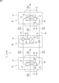
- the ventilation system 10 of the present disclosure shown in FIG. 1 is installed in a building such as a building or a factory, and realizes ventilation of a target space in the building.
- the ventilation system 10 includes an air supply unit 20 , an exhaust unit 30 , a compressor unit 40 and a refrigerant circuit 50 .
- the air supply unit 20 includes a first casing 21, an air supply fan 22, and a first heat exchanger 23.
- the first casing 21 of the present embodiment is a cubic box made of heat-insulating panel members, and has a suction port 24 and a discharge port 25 formed on its side surfaces.
- the air supply fan 22 and the first heat exchanger 23 are arranged inside the first casing 21 .
- the air supply unit 20 drives the air supply fan 22, the air (outside air OA) of the outdoors (hereinafter referred to as outdoor S2, see FIGS.
- the first heat exchanger 23 constitutes a refrigerant circuit 50 that will be described later.
- the first heat exchanger 23 is a cross-fin tube type or microchannel type heat exchanger, and is used to exchange heat between the refrigerant flowing in the first heat exchanger 23 and the outdoor air S2 (outside air OA). .
- the air supply unit 20 includes a supply air temperature sensor 26 and an outside air temperature sensor 27 .
- the supply air temperature sensor 26 is arranged in the flow of air after passing through the first heat exchanger 23 in the first casing 21, and measures the temperature T1 of the supply air SA (hereinafter referred to as the blown air temperature T1). to detect
- the outside air temperature sensor 27 is arranged in the flow of air before passing through the first heat exchanger 23 in the first casing 21, and detects the temperature T2 of the outside air OA (hereinafter referred to as the outside air temperature T2). .
- the air supply unit 20 includes a first heat exchanger temperature sensor 55 and a first refrigerant temperature sensor 56.
- the first heat exchanger temperature sensor 55 detects the temperature Tb1 of the first heat exchanger 23 (in other words, the refrigerant inside the first heat exchanger 23).
- the first refrigerant temperature sensor 56 detects the temperature Ta2 of the refrigerant after passing through the first heat exchanger 23 (outlet).
- the first heat exchanger temperature sensor 55 may be a pressure sensor that detects the pressure in the first heat exchanger 23. In this case, the refrigerant temperature in the first heat exchanger 23 can be determined from the pressure detection value. Convert.
- the exhaust unit 30 includes a second casing 31, an exhaust fan 32, and a second heat exchanger 33.
- the second casing 31 of the present embodiment is a cubic box made of heat-insulating panel members, and has a suction port 34 and a discharge port 35 formed on its side surface.
- the exhaust fan 32 and the second heat exchanger 33 are arranged inside the second casing 31 .
- the exhaust unit 30 takes in the indoor S1 air (return air RA) into the second casing 31, and after heat-exchanging the taken-in air with the refrigerant in the second heat exchanger 33 , the air (exhaust EA) is discharged from the outlet 35 toward the outdoors S2.
- the second heat exchanger 33 constitutes a refrigerant circuit 50 which will be described later.
- the second heat exchanger 33 is a cross-fin tube type or microchannel type heat exchanger, and is used to heat-exchange the refrigerant flowing in the second heat exchanger 33 with the air (return air RA) of the indoor S1. be done.
- the exhaust unit 30 includes a return air temperature sensor 36.
- the return air temperature sensor 36 is arranged in the flow of air before passing through the second heat exchanger 33 inside the second casing 31, and detects the temperature T3 of the air flowing into the second heat exchanger 33. .
- this temperature T3 will be referred to as intake air temperature T3.
- the exhaust unit 30 includes a second heat exchanger temperature sensor 57 and a second coolant temperature sensor 58 .
- the second heat exchanger temperature sensor 57 detects the temperature Tb2 of the second heat exchanger 33 (in other words, the refrigerant inside the second heat exchanger 33).
- the second refrigerant temperature sensor 58 detects the temperature Tb3 of the refrigerant after passing through the second heat exchanger 33 (outlet).
- the second heat exchanger temperature sensor 57 may be a pressure sensor that detects the pressure inside the second heat exchanger 33. In this case, the refrigerant temperature inside the first heat exchanger 23 can be determined from the pressure detection value. Convert.
- the ventilation system 10 of the present disclosure includes the air supply fan 22 and the exhaust fan 32.
- the ventilation system 10 shown in FIG. 1 includes one air supply fan 22 and one exhaust fan 32, but in the ventilation system 10 of the present disclosure, the number of air supply fans 22 may be two or more.
- the number of exhaust fans 32 may be two or more.
- the compressor unit 40 includes a third casing 41 , a compressor 42 , a four-way switching valve 43 and an expansion valve 44 .
- the compressor unit 40 of this embodiment includes the third casing 41, the third casing 41 may be omitted. In this case, it is preferable to accommodate the compressor 42 and the four-way switching valve 43 in the first casing 21 of the air supply unit 20 or the second casing 31 of the exhaust unit 30 .
- the expansion valve 44 is housed in the compressor unit 40.
- the expansion valve 44 is installed in the first casing 21 of the air supply unit 20 or the second casing 31 of the exhaust unit 30. may be accommodated.
- the compressor unit 40 includes a low pressure sensor 52, a discharge pressure sensor 53, and a discharge temperature sensor 54.
- the low-pressure sensor 52 detects the pressure PL of refrigerant sucked into the compressor 42 . In the following description, this pressure PL will also be referred to as the low pressure PL.
- a discharge pressure sensor 53 detects the pressure PH of the refrigerant discharged from the compressor 42 . In the following description, this pressure PH is also referred to as high pressure PH.
- a discharge temperature sensor 54 detects the temperature Ta1 of the refrigerant discharged from the compressor 42 .
- the compressor 42 sucks in low-pressure gaseous refrigerant and discharges high-pressure gaseous refrigerant.
- the compressor 42 has a motor whose operating speed can be adjusted by inverter control.
- the compressor 42 is of a variable capacity type (capacity variable type) whose capacity (capacity) can be changed by inverter-controlling the motor.
- the compressor 42 may be of the constant capacity type. Note that the compressor 42 used in the ventilation system 10 of the present disclosure may be configured by connecting two or more compressors in parallel.
- the four-way switching valve 43 reverses the flow of the refrigerant in the refrigerant pipe, switches the refrigerant discharged from the compressor 42 to one of the first heat exchanger 23 and the second heat exchanger 33, and supplies the refrigerant.
- the ventilation system 10 can switch between a cooling operation for cooling the outside air OA and a heating operation for heating the outside air OA.
- the expansion valve 44 is composed of an electrically operated valve capable of adjusting the flow rate and pressure of the refrigerant.
- the ventilation system 10 controls the opening degree of the expansion valve 44 to adjust the pressure of the refrigerant supplied to the first heat exchanger 23 or the second heat exchanger 33 .
- the refrigerant circuit 50 includes a compressor 42, a four-way switching valve 43, an expansion valve 44, a first heat exchanger 23, a second heat exchanger 33, and refrigerant pipes 51 (a liquid pipe 51L and a gas pipe 51G) connecting these. contains.
- the refrigerant circuit 50 circulates refrigerant between the first heat exchanger 23 and the second heat exchanger 33 .
- the four-way switching valve 43 is held in the state indicated by the solid line in FIG.
- the high-temperature, high-pressure gaseous refrigerant discharged from the compressor 42 flows into the second heat exchanger 33 of the exhaust unit 30 via the four-way switching valve 43 .
- the second heat exchanger 33 functions as a condenser, and the operation of the exhaust fan 32 causes the refrigerant to exchange heat with the return air RA to condense and liquefy.
- the liquefied refrigerant is depressurized by the expansion valve 44 and flows into the first heat exchanger 23 .
- the first heat exchanger 23 functions as an evaporator, and in the first heat exchanger 23, the refrigerant exchanges heat with the outside air OA and evaporates.
- the outside air OA cooled by the evaporation of the refrigerant is supplied to the indoor S1 as supply air SA by the air supply fan 22 .
- the refrigerant evaporated in the first heat exchanger 23 returns to the compressor unit 40 through the refrigerant pipe 51 (gas pipe 51G) and is sucked into the compressor 42 through the four-way switching valve 43 .
- the four-way switching valve 43 is held in the state indicated by the dashed line in FIG.
- the high-temperature, high-pressure gaseous refrigerant discharged from the compressor 42 passes through the four-way switching valve 43 and flows into the first heat exchanger 23 of the air supply unit 20 .
- the first heat exchanger 23 functions as a condenser, and in the first heat exchanger 23, the refrigerant exchanges heat with the outside air OA to condense and liquefy.
- the outside air OA heated by condensation of the refrigerant is supplied to the indoor S1 by the air supply fan 22 .
- the refrigerant liquefied in the first heat exchanger 23 passes through the refrigerant pipe 51 (liquid pipe 51L), reaches the compressor unit 40, is decompressed to a predetermined low pressure by the expansion valve 44, and then flows into the second heat exchanger 33. do.
- the second heat exchanger 33 functions as an evaporator, and in the second heat exchanger 33, the refrigerant exchanges heat with the return air RA and evaporates.
- the refrigerant evaporated/vaporized in the second heat exchanger 33 is sucked into the compressor 42 via the four-way switching valve 43 .
- the ventilation system 10 of the present embodiment includes a four-way switching valve 43 in the refrigerant circuit 50, and the four-way switching valve 43 can be used to switch the first heat exchanger 23 as an evaporator and a condenser.
- the four-way switching valve 43 in the ventilation system 10 may be omitted.
- the first heat exchanger 23 can be used as an evaporator or a condenser.
- FIG. 2 is a control block diagram of the ventilation system 10. As shown in FIG. As shown in FIG. 2 , the ventilation system 10 has a controller 16 .
- the control unit 16 is a device that controls the operation of the ventilation system 10, and is configured by, for example, a microcomputer having a processor such as a CPU and memories such as RAM and ROM.
- the control unit 16 may be realized as hardware using LSI, ASIC, FPGA, or the like.
- the control unit 16 exhibits a predetermined function when the processor executes a program installed in the memory.
- the control unit 16 is connected to the air supply fan 22, the exhaust fan 32, the compressor 42, the four-way switching valve 43, the expansion valve 44, and the notification unit 45.
- the controller 16 is connected to the supply air temperature sensor 26 , the outside air temperature sensor 27 and the return air temperature sensor 36 .
- the control unit 16 includes a low pressure sensor 52, a discharge pressure sensor 53, a discharge temperature sensor 54, a first heat exchanger temperature sensor 55, a first refrigerant temperature sensor 56, and a second heat exchanger temperature sensor provided at various locations in the refrigerant circuit 50. 57 and a second coolant temperature sensor 58 .
- the detection values of the sensors 52 to 58 provided in the refrigerant circuit 50 are also referred to as status values of the refrigerant circuit 50.
- the control unit 16 grasps the operating state of the refrigerant circuit 50 based on the state value of the refrigerant circuit 50 .
- the control unit 16 when the outside air OA is heated and supplied in the air supply unit 20, the control unit 16 functions as an evaporator based on the detection value (high pressure PH) of the discharge pressure sensor 53. 2 Calculate the saturation temperature TS of the heat exchanger 33, obtain the low pressure PL of the refrigerant circuit 50 from the detection value of the low pressure sensor 52, 2 Obtain the evaporation temperature TE of the heat exchanger 33 .
- the saturation temperature TS, the low pressure PL, and the evaporation temperature TE are examples of state values of the refrigerant circuit 50 .
- the control unit 16 stores a threshold value for determining whether each state value of the refrigerant circuit 50 is normal or abnormal. When the obtained state value exceeds the threshold, the control unit 16 determines that the refrigerant circuit 50 has reached a state where it cannot maintain its function. In this description, the state in which the refrigerant circuit 50 cannot maintain its function is also referred to as "the state value of the refrigerant circuit 50 exceeds the allowable range”.
- the control unit 16 is configured to be able to individually acquire information related to the operating current values and fan rotation speeds of the air supply fan 22 and the exhaust fan 32 .
- the control unit 16 determines whether or not the air supply fan 22 is normal based on the correlation between the fan rotation speed and the operating current value of the air supply fan 22, and also determines the relationship between the fan rotation speed and the operating current value of the exhaust fan 32. Based on the correlation, it is determined whether the exhaust fan 32 is normal.
- the controller 16 can determine whether the air supply fan 22 or the exhaust fan 32 is normal without providing a separate sensor.
- the control unit 16 determines whether or not there is a sign that an abnormality will occur in the air supply fan 22 and the exhaust fan 32 based on information related to the individual operating current values and fan rotational speeds of the air supply fan 22 and the exhaust fan 32. It has the function of making judgments. For example, the control unit 16 determines whether an abnormality has occurred based on the operating current values of the air supply fan 22 and the exhaust fan 32 when they are started, and the correlation between the operating current values of the air supply fan 22 and the exhaust fan 32 and the fan rotation speed. Determine whether or not there is an omen.
- the notification unit 45 of the present embodiment is a remote controller for the user to operate/stop the ventilation system 10 and change settings, etc., and is arranged in the target space (indoor S1) to be ventilated by the ventilation system 10 .
- the notification unit 45 notifies that an abnormality has occurred in the ventilation system 10 by sound (including buzzer sound, voice, etc.) and display (including lighting of a lamp, display by a liquid crystal panel, etc.).
- the remote controller for the ventilation system 10 also serves as the notification unit 45, but the notification unit 45 may be configured by a device other than the remote controller.
- the location of the notification unit 45 does not have to be indoors S1, and may be, for example, a location (central monitoring room) where the manager of the ventilation system 10 is present.
- the notification unit 45 notifies.
- the user can grasp the fan that is highly likely to have an abnormality from the information presented by the notification unit 45 .
- the user can repair the air supply fan 22 and the exhaust fan 32 before an abnormality occurs.
- the control unit 16 predicts the occurrence of an abnormality in the air supply fan 22 and the exhaust fan 32, and the notification unit 45 notifies the user of an abnormality that requires stopping during use. It is possible to suppress the occurrence, thereby enabling the reliable operation of the ventilation system 10 to continue.
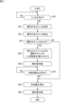
- FIG. 3 is a first flow chart showing operations when an abnormality occurs in the ventilation system of the present disclosure.
- FIG. 4 is a second flow diagram showing operations when an abnormality occurs in the ventilation system of the present disclosure.
- the control operation shown in FIG. 3 or 4 is executed when an abnormality occurs in the air supply fan 22 or the exhaust fan 32 .
- the controller 16 determines whether the air supply fan 22 and the exhaust fan 32 are normal (S01). In this description, when the air supply fan 22 and the exhaust fan 32 are not malfunctioning and the operating current value and the fan rotation speed are normal, the control unit 16 controls the air supply fan 22 and the exhaust fan 32 is normal. In this description, when the air supply fan 22 is not normal, it is said that the air supply fan 22 is abnormal, and when the exhaust fan 32 is not normal, it is said that the exhaust fan 32 is abnormal.
- step (S01) if the air supply fan 22 and the exhaust fan 32 are normal (YES), the control unit 16 repeats step (S01).
- step (S01) if the air supply fan 22 and the exhaust fan 32 are abnormal (NO), the control section 16 executes step (S02).
- step (S02) the control unit 16 identifies the abnormal fan (air supply fan 22 or exhaust fan 32) out of the air supply fan 22 and the exhaust fan 32, and proceeds to step (S03).
- step (S03) the control unit 16 stops the fan (air supply fan 22 or exhaust fan 32) identified as having an abnormality among the air supply fan 22 and the exhaust fan 32, and proceeds to step (S04). .
- step (S04) the control unit 16 determines whether or not there is an air supply fan 22 and an exhaust fan 32 in operation. If it is determined in step (S04) that there is an air supply fan 22 and an exhaust fan 32 in operation (YES), the controller 16 executes step (S05). If it is determined in step (S04) that there is no air supply fan 22 or exhaust fan 32 in operation (NO), the control section 16 proceeds to step (S08).
- step ( S ⁇ b>05 ) the control unit 16 increases the fan rotation speed of the operating fan other than the stopped fan (the air supply fan 22 or the exhaust fan 32 ), out of the air supply fan 22 and the exhaust fan 32 . , the process proceeds to step (S06). Note that in the ventilation system 10 of the present disclosure, step (S05) may be omitted, and step (S06) may be executed after step (S04) is executed.
- step (S06) the control unit 16 operates the notification unit 45 to notify the user that the abnormal fan (air supply fan 22 or exhaust fan 32) has been stopped, and proceeds to step (S07). .
- step (S07) the control unit 16 determines whether or not the refrigerant circuit 50 is normal. In this description, it may be said that the refrigerant circuit 50 is abnormal when the refrigerant circuit 50 is not normal. Here, "abnormality of the refrigerant circuit 50" means that the state value of the refrigerant circuit 50 exceeds the allowable range.
- step (S07) if it is determined that the refrigerant circuit 50 is normal (YES), the control unit 16 repeats the step ( S07) is executed. If it is determined in step (S07) that there is an abnormality in the refrigerant circuit 50 (NO), the controller 16 executes step (S08).
- step (S08) the control unit 16 stops the compressor 42 to protect the refrigerant circuit 50, and proceeds to step (S09).
- step (S09) the control unit 16 operates the notification unit 45 to notify the user that the compressor 42 has stopped, and ends the series of control operations. If the determination in step (S04) is (NO) and the process proceeds from step (S04) to step (S08), the control unit 16 turns off the fans 22 and 32 and the compressor 42 in step (S09). The notification unit 45 notifies that the motor has been stopped. The control unit 16 continues control of the ventilation system 10 according to the flow chart shown in FIG. 3 as long as the air supply fan 22 and the exhaust fan 32 are in operation.
- the ventilation system 10 can continue to ventilate the indoor S1 even if an abnormality occurs in the air supply fan 22 or the exhaust fan 32.
- the ventilation system 10 can continue to operate the compressor 42 as long as the refrigerant circuit 50 does not malfunction.
- the temperature control of the supply air SA by the refrigerant circuit 50 or the heat recovery from the exhaust EA can be continued by activating the function of the fan (the supply air fan 22 or the exhaust fan 32) in which no abnormality has occurred. can.
- the ventilation system 10 suppresses deterioration of comfort level and heat recovery efficiency of the indoor S1 even when an abnormality occurs in the air supply fan 22 or the exhaust fan 32. can be done.
- the ventilation system 10 of the present disclosure may be controlled according to the flow shown in FIG. 4 when an abnormality occurs in the air supply fan 22 and the exhaust fan 32.
- step (S11) determines whether the air supply fan 22 and the exhaust fan 32 are normal (S11). If it is determined in step (S11) that the air supply fan 22 and the exhaust fan 32 are normal (YES), the controller 16 repeats step (S11). When it is determined in step (S11) that the air supply fan 22 and the exhaust fan 32 are abnormal (NO), the control section 16 executes step (S12).
- step (S12) the control unit 16 identifies the abnormal fan out of the air supply fan 22 and the exhaust fan 32, and proceeds to step (S13).
- step (S13) the control unit 16 stops the fan identified as having an abnormality among the air supply fan 22 and the exhaust fan 32, stops the compressor 42, and proceeds to step (S14).
- step (S14) the control unit 16 determines whether or not there is an air supply fan 22 and an exhaust fan 32 in operation. If it is determined in step (S14) that there are the air supply fan 22 and the exhaust fan 32 in operation (YES), the controller 16 executes step (S15). If it is determined in step (S14) that there is no air supply fan 22 or exhaust fan 32 in operation (NO), the controller 16 proceeds to step (S16).
- step (S15) the control unit 16 increases the fan rotation speed of the operating fan other than the stopped fan (the air supply fan 22 or the exhaust fan 32), out of the air supply fan 22 and the exhaust fan 32. , the process proceeds to step (S16). Note that in the ventilation system 10 of the present disclosure, step (S15) may be omitted, and step (S16) may be performed after step (S14) is performed.
- step (S16) the control unit 16 operates the notification unit 45 to notify the user that the abnormal fan (air supply fan 22 or exhaust fan 32) and the compressor 42 have been stopped. end the control operation of (END).
- the control unit 16 continues control of the ventilation system 10 according to the flow chart shown in FIG. 4 as long as the air supply fan 22 and the exhaust fan 32 are in operation.
- FIG. 5 is a schematic configuration diagram showing the state of arrangement of the ventilation system with respect to the building according to the first embodiment of the present disclosure.
- FIG. 6 is a schematic configuration diagram of a ventilation system according to the first embodiment of the present disclosure;
- the first ventilation system 11 shown in FIGS. 5 and 6 is the first embodiment of the ventilation system 10 of the present disclosure.
- the first ventilation system 11 includes one air supply unit 20 , one exhaust unit 30 , a compressor unit 40 and a refrigerant circuit 50 .
- the air supply unit 20 and the exhaust unit 30 are in one-to-one correspondence.
- the first ventilation system 11 is configured integrally with an air supply unit 20, an exhaust unit 30, and a compressor unit 40, but each unit 20, 30, 40 can be separated. and can be placed separately.
- parts common to the first and second ventilation systems 11 and 12 are denoted by the same reference numerals, and repeated explanations of the parts denoted by the same reference numerals are omitted.
- the first ventilation system 11 can be placed outdoors S2, for example.
- the outlet 25 of the air supply unit 20 and the inlet 34 of the exhaust unit 30 are directly attached to the outer wall surface of the building B.
- ducts are connected to the outlet 25 and the inlet 34 so that the position where the supply air SA is released to the indoor S1 and the position where the return air RA is sucked from the indoor S1 can be adjusted.
- the first ventilation system 11 may be placed entirely indoors S1.
- the unit 30 and the compressor unit 40 may be separated so that one part is placed outdoors S2 and the remaining part is placed indoors S1.
- the control unit 16 determines that there is an abnormality in the air supply fan 22 or the exhaust fan 32 (S01), the abnormal fan is specified (S02), and the abnormal fan ( The air supply fan 22 or exhaust fan 32) is stopped (S03). If the stopped fan is the air supply fan 22 , the control unit 16 continues the operation of the exhaust fan 32 . In this case, the first ventilation system 11 can continue ventilation (type 3 ventilation) only with the exhaust fan 32 for the indoor S1. If the stopped fan is the exhaust fan 32 , the controller 16 continues the operation of the air supply fan 22 . In this case, the first ventilation system 11 can continue ventilation (second type ventilation) only by the air supply fan 22 for the indoor S1.
- the control unit 16 After stopping the abnormal fan (air supply fan 22 or exhaust fan 32), the control unit 16 increases the fan rotation speed of the fan (air supply fan 22 or exhaust fan 32) that continues to operate. , the air volume of the fan is increased (S05). In the first ventilation system 11, this makes it possible to suppress a decrease in the amount of ventilation in the indoor S1 due to the stoppage of the air supply fan 22 or the exhaust fan 32.
- the control unit 16 After stopping the abnormal fan (the air supply fan 22 or the exhaust fan 32), the control unit 16 operates the notification unit 45 arranged in the indoor S1 to notify the user or the like of the air supply fan 22 or the exhaust fan 32. stops (S06). The operation of the notification unit 45 at this time allows the user to grasp that the ventilation state of the indoor room S1 has changed.
- the control unit 16 After stopping the abnormal fan (air supply fan 22 or exhaust fan 32), the control unit 16 acquires the state value of the refrigerant circuit 50, and when it is determined that the state value exceeds the allowable range, the compressor 42 is stopped (S08).
- the first ventilation system 11 when an abnormality occurs in the air supply fan 22 or the exhaust fan 32, ventilation of the indoor S1 can be continued while performing heat exchange and heat recovery by the refrigerant circuit 50 as much as possible.
- the control unit 16 After stopping the refrigerant circuit 50, the control unit 16 operates the notification unit 45 to notify the user or the like that the compressor 42 has stopped (S09). The user can understand that the temperature in the indoor area S1 may change due to the operation of the notification unit 45 at this time.
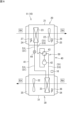
- FIG. 7 is a schematic configuration diagram of a ventilation system according to a second embodiment of the present disclosure.
- a second ventilation system 12 shown in FIG. 7 is a second embodiment of the ventilation system 10 of the present disclosure.
- the second ventilation system 12 differs from the first ventilation system 11 described above in that it has a plurality of air supply units 20 and exhaust units 30 .
- the second ventilation system 12 ventilates a room R1 provided indoors S1.
- the second ventilation system 12 includes two air supply units 20 and two exhaust units 30 for the room R1.
- one of the two air supply units 20 will be referred to as the first air supply unit 20A
- the other air supply unit 20 will be referred to as the second air supply unit 20B
- one of the two exhaust units 30 will be referred to as the second air supply unit.
- 1 exhaust unit 30A, and the other exhaust unit 30 is referred to as a second exhaust unit 30B.
- the first air supply unit 20A has a first air supply fan 22A
- the second air supply unit 20B has a second air supply fan 22B.
- the first exhaust unit 30A has a first exhaust fan 32A
- the second exhaust unit 30B has a second exhaust fan 32B.
- the second ventilation system 12 of the present embodiment includes two air supply units 20 and two exhaust units 30, the number of air supply units 20 and exhaust units 30 in the second ventilation system 12 is It is not limited to this, and the number of each may be three or more, or the number of any one may be one. In the second ventilation system 12 of this embodiment, the numbers of the air supply units 20 and the number of the exhaust units 30 may be different.
- the outside air OA taken in from the outside air intake 28 provided in the outer wall of the building B is distributed to the air supply units 20A and 20B by the air supply duct 29.
- a plurality of supply air fans 22 supply supply air SA to the room R1
- a plurality of exhaust fans 32 exhaust return air RA in an amount that balances the amount of supply air SA from the room R1. Release as EA.
- the total air volume of the air supply SA from the plurality of air supply units 20 and the total air volume of the exhaust air EA from the plurality of exhaust units 30 are balanced.
- the control unit 16 determines that any one of the first air supply fan 22A, the second air supply fan 22B, the first exhaust fan 32A, and the second exhaust fan 32B has an abnormality. If so (S01), the abnormal fan is specified (S02), and the abnormal fan is stopped (S03). For example, when the stopped fan is the first air supply fan 22A, the control unit 16 continues the operation of the second air supply fan 22B, the first exhaust fan 32A, and the second exhaust fan 32B. In this case, the first ventilation system 11 can continue ventilation (type 1 ventilation) for the indoor S1. In the second ventilation system 12, even if one of the fans is stopped, the ventilation of the indoor S1 (first-class ventilation) can be continued by continuing the operation of the remaining fans.
- the control unit 16 increases the fan rotation speed of the second air supply fan 22B among the fans that continue to operate.
- the air supply amount of the air supply fan 22B is increased.
- the first ventilation system 11 by bringing the balance of the air supply amount and the exhaust amount close to a normal state, it is possible to suppress the decrease in the ventilation amount of the indoor S1 due to the stoppage of the first air supply fan 22A.
- the second ventilation system 12 when the first air supply fan 22A is stopped, not only the second air supply fan 22B but also each fan rotation speed of the first exhaust fan 32A and the second exhaust fan 32B are increased. may be increased. In other words, in the second ventilation system 12, when one of the fans is stopped, the fan rotation speeds of all the remaining fans may be increased to suppress a decrease in the amount of ventilation in the indoor S1.
- the control unit 16 determines that any one of the first air supply fan 22A, the second air supply fan 22B, the first exhaust fan 32A, and the second exhaust fan 32B has an abnormality. If so (S11), the abnormal fan is specified (S12), and the abnormal fan and the compressor 42 are stopped (S13).
- the stopped fan is the first air supply fan 22A
- the control unit 16 continues the operation of the second air supply fan 22B, the first exhaust fan 32A, and the second exhaust fan 32B.
- the second ventilation system 12 can continue ventilation (first-class ventilation) by the second supply fan 22B, the first exhaust fan 32A, and the second exhaust fan 32B for the indoor S1.
- the compressor 42, the first heat exchanger 23, and the second heat exchanger 33 are connected by a refrigerant pipe 51, and the refrigerant flows inside A refrigerant circuit 50, an air supply fan 22 that supplies the air of the outdoor S2 to the indoor S1 through the first heat exchanger 23, and an exhaust fan 32 that exhausts the air of the indoor S1 to the outdoor S2 through the second heat exchanger 33. , and a control unit 16 .
- the control unit 16 determines whether the air supply fan 22 and the exhaust fan 32 are normal. When determining that one of the fans 22, 32 is abnormal, the control unit 16 stops the one of the fans 22, 32 determined to be abnormal, and continues the operation of the other fan 22, 32 determined to be normal. .
- the controller 16 acquires the state value of the refrigerant circuit 50 and stops the compressor 42 when it determines that the state value exceeds the allowable range.
- the ventilation system 10 having such a configuration, when an abnormality occurs in the air supply fan 22 or the exhaust fan 32, ventilation of the indoor S1 is continued while performing heat exchange and heat recovery by the refrigerant circuit 50 as much as possible. can do.
- the ventilation system 10 shown in the above embodiment stops the compressor 42 when the controller 16 determines that the air supply fan 22 or the exhaust fan 32 is abnormal.
- the ventilation system 10 having such a configuration, even if an abnormality occurs in the air supply fan 22 or the exhaust fan 32, ventilation of the indoor S1 can be reliably continued.
- the ventilation system 10 shown in the above embodiment further includes a notification unit 45 that notifies abnormality of the air supply fan 22 or the exhaust fan 32 .
- the notification unit 45 is activated.
- the notification unit 45 can notify the user or the like that an abnormality has occurred in the air supply fan 22 or the exhaust fan 32 .
- the controller 16 determines whether the air supply fan 22 is normal based on the correlation between the fan rotation speed of the air supply fan 22 and the operating current value. , whether or not the exhaust fan 32 is normal is determined based on the correlation between the fan rotation speed of the exhaust fan 32 and the operating current value.
- the ventilation system 10 having such a configuration, it is possible to determine whether or not there is an abnormality in the air supply fan 22 or the exhaust fan 32 by the control unit 16 without providing a separate sensor.
- the first ventilation system 11 having such a configuration, when the air supply fan 22 or the exhaust fan 32 with an abnormality is stopped, it is possible to suppress a decrease in the amount of ventilation in the indoor S1.
- the air supply fan 22 includes the first air supply fan 22A and the second air supply fan 22B
- the exhaust fan 32 includes the first air supply fan 32A. and a second exhaust fan 32B.
- the control unit 16 determines whether the first air supply fan 22A, the second air supply fan 22B, the first exhaust fan 32A, and the second exhaust fan 32B are normal, and one of the fans 22, 32 is abnormal. If so, the operation of the remaining fans 22, 32 judged to be normal is continued.
- the controller 16 controls any one of the first air supply fan 22A, the second air supply fan 22B, the first exhaust fan 32A, and the second exhaust fan 32B. If one is determined to be abnormal, the fan rotation speed of the fans 22 and 32 determined to be normal is increased.
- the ventilation system 10 having such a configuration, it is possible to suppress a decrease in the amount of ventilation in the indoor S1 when the air supply fan 22 or the exhaust fan 32 with an abnormality is stopped.
- control unit 16 predicts an abnormality of the air supply fan 22 based on the operation data of the air supply fan 22, and based on the operation data of the exhaust fan 32 Abnormality of the exhaust fan 32 is predicted.
- preventive maintenance can be performed on the air supply fan 22 and the exhaust fan 32 before an abnormality occurs. occurrence can be suppressed. As a result, it is possible to reliably ensure the ventilation rate of the indoor S1.
- Ventilation system 11 First ventilation system 12: Second ventilation system 16: Control unit 22: Air supply fan 22A: First air supply fan 22B: Second air supply fan 23: First heat exchanger 32: Exhaust fan 32A: First exhaust fan 32B: Second exhaust fan 33: Second heat exchanger 42: Compressor 45: Notification unit 50: Refrigerant circuit 51: Refrigerant pipe S1: Indoor S2: Outdoor
Landscapes
- Engineering & Computer Science (AREA)
- Mechanical Engineering (AREA)
- General Engineering & Computer Science (AREA)
- Chemical & Material Sciences (AREA)
- Combustion & Propulsion (AREA)
- Physics & Mathematics (AREA)
- Thermal Sciences (AREA)
- Health & Medical Sciences (AREA)
- Biomedical Technology (AREA)
- Air Conditioning Control Device (AREA)
- Ventilation (AREA)
Abstract
Description
図1は、本開示の換気システムの概略的な構成図である。図2は、本開示の換気システムの制御ブロック図である。なお、以下の説明では、第1実施形態に係る換気システム10(図5及び図6参照)を第1換気システム11と称し、第2実施形態に係る換気システム10(図7参照)を第2換気システム12と称する。以下の説明において、単に「換気システム10」と記載する場合は、第1換気システム11及び第2換気システム12で共通する構成について説明している。
図2は、換気システム10の制御ブロック図である。図2に示すように、換気システム10は、制御部16を有する。制御部16は、換気システム10の動作を制御する装置であり、例えば、CPU等のプロセッサ、RAM、ROM等のメモリを備えたマイクロコンピュータにより構成される。制御部16は、LSI、ASIC、FPGA等を用いてハードウェアとして実現されるものであってもよい。制御部16は、メモリにインストールされたプログラムをプロセッサが実行することによって、所定の機能を発揮する。
本実施形態の報知部45は、ユーザが換気システム10の運転・停止、及び設定変更等を行うリモコンであり、換気システム10により換気を行う対象空間(屋内S1)に配置される。報知部45は、音(ブザー音、音声等を含む)や表示(ランプの点灯や液晶パネルによる表示等を含む)によって、換気システム10に異常が発生したことを報知する。なお、本実施形態では、換気システム10のためのリモコンが報知部45を兼ねているが、報知部45はリモコン以外の機器によって構成してもよい。報知部45の配置場所は、屋内S1でなくてもよく、例えば、換気システム10の管理者がいる場所(中央監視室)等であってもよい。
図3は、本開示の換気システムに異常が発生した場合の動作を示す第1フロー図である。図4は、本開示の換気システムに異常が発生した場合の動作を示す第2フロー図である。本開示の換気システム10は、給気ファン22及び排気ファン32に異常が発生した場合に、図3又は図4に示す制御動作が実行される。
換気システム10についての図3に示した制御動作を説明する。図3に示すように、換気システム10の運転が開始されると、制御部16は、給気ファン22及び排気ファン32が正常であるか否かを判断する(S01)。なお、本説明では、給気ファン22及び排気ファン32に故障がなく、運転電流値及びファン回転数が正常な状態で運転されている場合に、制御部16が、給気ファン22及び排気ファン32が正常であると判断する。本説明では、給気ファン22が正常でないことを、給気ファン22が異常であると言い、排気ファン32が正常でないことを、排気ファン32が異常であると言う。
図5は、本開示の第1実施形態に係る換気システムの建物に対する配置状態を示す概略的な構成図である。図6は、本開示の第1実施形態に係る換気システムの概略的な構成図である。図5及び図6に示す第1換気システム11は、本開示の換気システム10の第1実施形態である。第1換気システム11は、1台の給気ユニット20、1台の排気ユニット30、圧縮機ユニット40、及び冷媒回路50を備える。換言すると、第1換気システム11では、給気ユニット20と排気ユニット30とが、1対1で対応している。第1換気システム11は、図5及び図6に示す形態では、給気ユニット20、排気ユニット30、及び圧縮機ユニット40が一体に構成されるが、各ユニット20,30,40は分離可能であり、それぞれを分離させて配置することが可能である。なお、以下の説明において、第1、第2の各換気システム11,12で共通する部分には同じ符号を付しており、同じ符号が付された部分については繰り返しの説明を省略する。
図7は、本開示の第2実施形態に係る換気システムの概略的な構成図である。図7に示す第2換気システム12は、本開示の換気システム10の第2実施形態である。第2換気システム12は、給気ユニット20及び排気ユニット30が複数である点で、前述した第1換気システム11と異なっている。
(1)上記実施形態に示した第1換気システム11は、圧縮機42と、第1熱交換器23と、第2熱交換器33と、が冷媒配管51によって接続され、内部を冷媒が流れる冷媒回路50と、第1熱交換器23を通して屋外S2の空気を屋内S1に給気する給気ファン22と、第2熱交換器33を通して屋内S1の空気を屋外S2に排気する排気ファン32と、制御部16と、を備える。制御部16は、給気ファン22及び排気ファン32が正常かどうかを判断する。制御部16は、一方のファン22,32が異常であると判断した場合、異常と判断した一方のファン22,32を停止させると共に、正常と判断した他方のファン22,32の運転を継続させる。
11 :第1換気システム
12 :第2換気システム
16 :制御部
22 :給気ファン
22A :第1給気ファン
22B :第2給気ファン
23 :第1熱交換器
32 :排気ファン
32A :第1排気ファン
32B :第2排気ファン
33 :第2熱交換器
42 :圧縮機
45 :報知部
50 :冷媒回路
51 :冷媒配管
S1 :屋内
S2 :屋外
Claims (9)
- 圧縮機(42)と、第1熱交換器(23)と、第2熱交換器(33)と、が冷媒配管(51)によって接続され、内部を冷媒が流れる冷媒回路(50)と、
前記第1熱交換器(23)を通して屋外(S2)の空気を屋内(S1)に給気する給気ファン(22)と、
前記第2熱交換器(33)を通して前記屋内(S1)の空気を前記屋外(S2)に排気する排気ファン(32)と、
制御部(16)と、を備え、
前記制御部(16)が、前記給気ファン(22)及び前記排気ファン(32)が正常かどうかを判断し、一方の前記ファン(22,32)が異常であると判断した場合、異常と判断した一方の前記ファン(22,32)を停止させると共に、正常と判断した他方の前記ファン(22,32)の運転を継続させる、換気システム(10,11)。 - 前記制御部(16)が、前記冷媒回路(50)の状態値を取得し、前記状態値が許容範囲を超えたと判断した場合、前記圧縮機(42)を停止させる、請求項1に記載の換気システム(10)。
- 前記制御部(16)が、前記給気ファン(22)又は前記排気ファン(32)が異常であると判断した場合、
前記圧縮機(42)を停止させる、請求項1に記載の換気システム(10)。 - 前記給気ファン(22)又は前記排気ファン(32)の異常を報知する報知部(45)をさらに備え、
前記制御部(16)が、前記給気ファン(22)又は前記排気ファン(32)が異常であると判断した場合、
前記報知部(45)を作動させる、請求項1~3の何れか一項に記載の換気システム(10)。 - 前記制御部(16)が、前記給気ファン(22)のファン回転数と運転電流値との相関に基づいて当該給気ファン(22)が正常かどうかを判断すると共に、前記排気ファン(32)のファン回転数と運転電流値との相関に基づいて当該排気ファン(32)が正常かどうかを判断する、請求項1~4の何れか一項に記載の換気システム(10)。
- 前記制御部(16)が、前記給気ファン(22)及び前記排気ファン(32)の一方が異常であると判断した場合、
正常と判断した他方の前記ファン(22,32)のファン回転数を増大させる、請求項1~5の何れか一項に記載の換気システム(11)。 - 前記給気ファン(22)が、第1給気ファン(22A)と、第2給気ファン(22B)とを含み、
前記排気ファン(32)が、第1排気ファン(32A)と、第2排気ファン(32B)とを含み、
前記制御部(16)が、前記第1給気ファン(22A)、前記第2給気ファン(22B)、前記第1排気ファン(32A)及び前記第2排気ファン(32B)が正常かどうかを判断し、何れか1つの前記ファン(22,32)が異常であると判断した場合、正常と判断した残りの前記ファン(22,32)の運転を継続させる、請求項1~6の何れか一項に記載の換気システム(10,12)。 - 前記制御部(16)が、前記第1給気ファン(22A)、前記第2給気ファン(22B)、前記第1排気ファン(32A)及び前記第2排気ファン(32B)の何れか1つが異常であると判断した場合、正常と判断した前記ファン(22,32)のファン回転数を増大させる、請求項7に記載の換気システム(12)。
- 前記制御部(16)が、前記給気ファン(22)の運転データに基づいて当該給気ファン(22)の異常を予知すると共に、前記排気ファン(32)の運転データに基づいて当該排気ファン(32)の異常を予知する、請求項1~8の何れか一項に記載の換気システム(10)。
Priority Applications (4)
| Application Number | Priority Date | Filing Date | Title |
|---|---|---|---|
| AU2022408269A AU2022408269B2 (en) | 2021-12-17 | 2022-10-31 | Ventilation system |
| CN202280083006.2A CN118401785A (zh) | 2021-12-17 | 2022-10-31 | 换气系统 |
| EP22907063.6A EP4450883B1 (en) | 2021-12-17 | 2022-10-31 | Ventilation system |
| US18/742,652 US20240328648A1 (en) | 2021-12-17 | 2024-06-13 | Ventilation system |
Applications Claiming Priority (2)
| Application Number | Priority Date | Filing Date | Title |
|---|---|---|---|
| JP2021-205442 | 2021-12-17 | ||
| JP2021205442A JP7295454B1 (ja) | 2021-12-17 | 2021-12-17 | 換気システム |
Related Child Applications (1)
| Application Number | Title | Priority Date | Filing Date |
|---|---|---|---|
| US18/742,652 Continuation US20240328648A1 (en) | 2021-12-17 | 2024-06-13 | Ventilation system |
Publications (1)
| Publication Number | Publication Date |
|---|---|
| WO2023112530A1 true WO2023112530A1 (ja) | 2023-06-22 |
Family
ID=86772742
Family Applications (1)
| Application Number | Title | Priority Date | Filing Date |
|---|---|---|---|
| PCT/JP2022/040691 Ceased WO2023112530A1 (ja) | 2021-12-17 | 2022-10-31 | 換気システム |
Country Status (6)
| Country | Link |
|---|---|
| US (1) | US20240328648A1 (ja) |
| EP (1) | EP4450883B1 (ja) |
| JP (1) | JP7295454B1 (ja) |
| CN (1) | CN118401785A (ja) |
| AU (1) | AU2022408269B2 (ja) |
| WO (1) | WO2023112530A1 (ja) |
Citations (10)
| Publication number | Priority date | Publication date | Assignee | Title |
|---|---|---|---|---|
| JPH0320573A (ja) | 1989-06-19 | 1991-01-29 | Sanyo Electric Co Ltd | 空気調和装置 |
| JPH11132512A (ja) * | 1997-10-27 | 1999-05-21 | Toshio Sakurazawa | 屋根裏用換気装置 |
| JP2001289493A (ja) * | 2000-04-06 | 2001-10-19 | Sanyo Electric Co Ltd | 空気調和機の制御方法 |
| JP2005291586A (ja) * | 2004-03-31 | 2005-10-20 | Daikin Ind Ltd | 空気調和システム |
| JP2006275431A (ja) * | 2005-03-29 | 2006-10-12 | Kyocera Corp | 換気装置のモーター制御方法 |
| JP2007010216A (ja) * | 2005-06-30 | 2007-01-18 | Daikin Ind Ltd | 換気装置 |
| JP2012060701A (ja) * | 2010-09-06 | 2012-03-22 | Fuji Electric Co Ltd | 複数台運転ファン駆動装置およびその故障処理方法 |
| JP2013137000A (ja) * | 2011-12-28 | 2013-07-11 | Noritz Corp | 給湯器およびファン用モータの制御装置 |
| JP2015108468A (ja) * | 2013-12-04 | 2015-06-11 | パナソニックIpマネジメント株式会社 | ファンフィルターユニットおよびファンフィルターユニット制御システム |
| JP2021055922A (ja) * | 2019-09-30 | 2021-04-08 | ダイキン工業株式会社 | 空調換気システム |
Family Cites Families (3)
| Publication number | Priority date | Publication date | Assignee | Title |
|---|---|---|---|---|
| JP2009109124A (ja) * | 2007-10-31 | 2009-05-21 | Daikin Ind Ltd | 調湿装置 |
| JP5668766B2 (ja) * | 2013-02-07 | 2015-02-12 | ダイキン工業株式会社 | 換気装置 |
| WO2017017846A1 (ja) * | 2015-07-30 | 2017-02-02 | 三菱電機株式会社 | 熱交換換気システム |
-
2021
- 2021-12-17 JP JP2021205442A patent/JP7295454B1/ja active Active
-
2022
- 2022-10-31 EP EP22907063.6A patent/EP4450883B1/en active Active
- 2022-10-31 AU AU2022408269A patent/AU2022408269B2/en active Active
- 2022-10-31 WO PCT/JP2022/040691 patent/WO2023112530A1/ja not_active Ceased
- 2022-10-31 CN CN202280083006.2A patent/CN118401785A/zh active Pending
-
2024
- 2024-06-13 US US18/742,652 patent/US20240328648A1/en active Pending
Patent Citations (10)
| Publication number | Priority date | Publication date | Assignee | Title |
|---|---|---|---|---|
| JPH0320573A (ja) | 1989-06-19 | 1991-01-29 | Sanyo Electric Co Ltd | 空気調和装置 |
| JPH11132512A (ja) * | 1997-10-27 | 1999-05-21 | Toshio Sakurazawa | 屋根裏用換気装置 |
| JP2001289493A (ja) * | 2000-04-06 | 2001-10-19 | Sanyo Electric Co Ltd | 空気調和機の制御方法 |
| JP2005291586A (ja) * | 2004-03-31 | 2005-10-20 | Daikin Ind Ltd | 空気調和システム |
| JP2006275431A (ja) * | 2005-03-29 | 2006-10-12 | Kyocera Corp | 換気装置のモーター制御方法 |
| JP2007010216A (ja) * | 2005-06-30 | 2007-01-18 | Daikin Ind Ltd | 換気装置 |
| JP2012060701A (ja) * | 2010-09-06 | 2012-03-22 | Fuji Electric Co Ltd | 複数台運転ファン駆動装置およびその故障処理方法 |
| JP2013137000A (ja) * | 2011-12-28 | 2013-07-11 | Noritz Corp | 給湯器およびファン用モータの制御装置 |
| JP2015108468A (ja) * | 2013-12-04 | 2015-06-11 | パナソニックIpマネジメント株式会社 | ファンフィルターユニットおよびファンフィルターユニット制御システム |
| JP2021055922A (ja) * | 2019-09-30 | 2021-04-08 | ダイキン工業株式会社 | 空調換気システム |
Non-Patent Citations (1)
| Title |
|---|
| See also references of EP4450883A4 |
Also Published As
| Publication number | Publication date |
|---|---|
| EP4450883B1 (en) | 2026-02-25 |
| US20240328648A1 (en) | 2024-10-03 |
| AU2022408269B2 (en) | 2024-07-25 |
| CN118401785A (zh) | 2024-07-26 |
| EP4450883A4 (en) | 2025-03-12 |
| JP2023090475A (ja) | 2023-06-29 |
| EP4450883A1 (en) | 2024-10-23 |
| AU2022408269A1 (en) | 2024-07-04 |
| JP7295454B1 (ja) | 2023-06-21 |
Similar Documents
| Publication | Publication Date | Title |
|---|---|---|
| US11927355B2 (en) | Air conditioning and ventilating system | |
| JP7019036B2 (ja) | 冷媒漏洩判定装置、空気調和機、及び冷媒漏洩判定方法 | |
| US11959652B2 (en) | Machine learning apparatus, air conditioning system, and machine learning method | |
| CN113883579B (zh) | 一种水系统空调 | |
| JP2021042918A (ja) | 空気調和システム | |
| US12111067B2 (en) | Air conditioning system | |
| JPWO2022085177A5 (ja) | ||
| JP7295454B1 (ja) | 換気システム | |
| JP6938950B2 (ja) | 空気調和システム | |
| JP2010190484A (ja) | 電子機器冷却装置 | |
| JP7438342B2 (ja) | 空気調和装置 | |
| KR101303239B1 (ko) | 공기조화기 및 그 제어방법 | |
| JP6370425B2 (ja) | 直膨コイルを使用した空気調和機 | |
| JP6111692B2 (ja) | 冷凍装置 | |
| KR20060124960A (ko) | 공기조화기의 냉방 운전 방법 | |
| KR20170075371A (ko) | 공기조화기 및 그 동작방법 | |
| JP4420393B2 (ja) | 冷凍空調装置 | |
| JP6716024B2 (ja) | 空気調和装置 | |
| US12584640B2 (en) | Ventilator | |
| JP7590654B2 (ja) | 換気システム | |
| JP7284407B2 (ja) | 換気システム | |
| KR101965182B1 (ko) | 공기조화기 및 그 제어방법 | |
| US20260029147A1 (en) | Air conditioning system | |
| WO2020035944A1 (ja) | 熱源システム | |
| CN118401787A (zh) | 换气装置、空调系统、换气方法以及换气系统 |
Legal Events
| Date | Code | Title | Description |
|---|---|---|---|
| 121 | Ep: the epo has been informed by wipo that ep was designated in this application |
Ref document number: 22907063 Country of ref document: EP Kind code of ref document: A1 |
|
| WWE | Wipo information: entry into national phase |
Ref document number: 2401003815 Country of ref document: TH |
|
| WWE | Wipo information: entry into national phase |
Ref document number: 202417046171 Country of ref document: IN Ref document number: 202280083006.2 Country of ref document: CN |
|
| WWE | Wipo information: entry into national phase |
Ref document number: 2022408269 Country of ref document: AU Ref document number: AU2022408269 Country of ref document: AU |
|
| WWE | Wipo information: entry into national phase |
Ref document number: 2022907063 Country of ref document: EP |
|
| NENP | Non-entry into the national phase |
Ref country code: DE |
|
| ENP | Entry into the national phase |
Ref document number: 2022907063 Country of ref document: EP Effective date: 20240717 |
|
| WWG | Wipo information: grant in national office |
Ref document number: 2022907063 Country of ref document: EP |