WO2023112794A1 - 熱交換ユニット - Google Patents
熱交換ユニット Download PDFInfo
- Publication number
- WO2023112794A1 WO2023112794A1 PCT/JP2022/045107 JP2022045107W WO2023112794A1 WO 2023112794 A1 WO2023112794 A1 WO 2023112794A1 JP 2022045107 W JP2022045107 W JP 2022045107W WO 2023112794 A1 WO2023112794 A1 WO 2023112794A1
- Authority
- WO
- WIPO (PCT)
- Prior art keywords
- heat
- heat exchange
- utilization
- heat exchanger
- exchange unit
- Prior art date
- Legal status (The legal status is an assumption and is not a legal conclusion. Google has not performed a legal analysis and makes no representation as to the accuracy of the status listed.)
- Ceased
Links
Images



Classifications
-
- F—MECHANICAL ENGINEERING; LIGHTING; HEATING; WEAPONS; BLASTING
- F28—HEAT EXCHANGE IN GENERAL
- F28F—DETAILS OF HEAT-EXCHANGE AND HEAT-TRANSFER APPARATUS, OF GENERAL APPLICATION
- F28F1/00—Tubular elements; Assemblies of tubular elements
- F28F1/02—Tubular elements of cross-section which is non-circular
-
- F—MECHANICAL ENGINEERING; LIGHTING; HEATING; WEAPONS; BLASTING
- F24—HEATING; RANGES; VENTILATING
- F24F—AIR-CONDITIONING; AIR-HUMIDIFICATION; VENTILATION; USE OF AIR CURRENTS FOR SCREENING
- F24F1/00—Room units for air-conditioning, e.g. separate or self-contained units or units receiving primary air from a central station
- F24F1/0007—Indoor units, e.g. fan coil units
- F24F1/0059—Indoor units, e.g. fan coil units characterised by heat exchangers
- F24F1/0063—Indoor units, e.g. fan coil units characterised by heat exchangers by the mounting or arrangement of the heat exchangers
-
- F—MECHANICAL ENGINEERING; LIGHTING; HEATING; WEAPONS; BLASTING
- F24—HEATING; RANGES; VENTILATING
- F24F—AIR-CONDITIONING; AIR-HUMIDIFICATION; VENTILATION; USE OF AIR CURRENTS FOR SCREENING
- F24F1/00—Room units for air-conditioning, e.g. separate or self-contained units or units receiving primary air from a central station
- F24F1/0007—Indoor units, e.g. fan coil units
- F24F1/0059—Indoor units, e.g. fan coil units characterised by heat exchangers
- F24F1/0067—Indoor units, e.g. fan coil units characterised by heat exchangers by the shape of the heat exchangers or of parts thereof, e.g. of their fins
-
- F—MECHANICAL ENGINEERING; LIGHTING; HEATING; WEAPONS; BLASTING
- F24—HEATING; RANGES; VENTILATING
- F24F—AIR-CONDITIONING; AIR-HUMIDIFICATION; VENTILATION; USE OF AIR CURRENTS FOR SCREENING
- F24F1/00—Room units for air-conditioning, e.g. separate or self-contained units or units receiving primary air from a central station
- F24F1/02—Self-contained room units for air-conditioning, i.e. with all apparatus for treatment installed in a common casing
- F24F1/032—Self-contained room units for air-conditioning, i.e. with all apparatus for treatment installed in a common casing characterised by heat exchangers
- F24F1/0323—Self-contained room units for air-conditioning, i.e. with all apparatus for treatment installed in a common casing characterised by heat exchangers by the mounting or arrangement of the heat exchangers
-
- F—MECHANICAL ENGINEERING; LIGHTING; HEATING; WEAPONS; BLASTING
- F24—HEATING; RANGES; VENTILATING
- F24F—AIR-CONDITIONING; AIR-HUMIDIFICATION; VENTILATION; USE OF AIR CURRENTS FOR SCREENING
- F24F1/00—Room units for air-conditioning, e.g. separate or self-contained units or units receiving primary air from a central station
- F24F1/02—Self-contained room units for air-conditioning, i.e. with all apparatus for treatment installed in a common casing
- F24F1/032—Self-contained room units for air-conditioning, i.e. with all apparatus for treatment installed in a common casing characterised by heat exchangers
- F24F1/0325—Self-contained room units for air-conditioning, i.e. with all apparatus for treatment installed in a common casing characterised by heat exchangers by the shape of the heat exchangers or of parts thereof, e.g. of their fins
-
- F—MECHANICAL ENGINEERING; LIGHTING; HEATING; WEAPONS; BLASTING
- F24—HEATING; RANGES; VENTILATING
- F24F—AIR-CONDITIONING; AIR-HUMIDIFICATION; VENTILATION; USE OF AIR CURRENTS FOR SCREENING
- F24F13/00—Details common to, or for air-conditioning, air-humidification, ventilation or use of air currents for screening
- F24F13/30—Arrangement or mounting of heat-exchangers
-
- F—MECHANICAL ENGINEERING; LIGHTING; HEATING; WEAPONS; BLASTING
- F28—HEAT EXCHANGE IN GENERAL
- F28D—HEAT-EXCHANGE APPARATUS, NOT PROVIDED FOR IN ANOTHER SUBCLASS, IN WHICH THE HEAT-EXCHANGE MEDIA DO NOT COME INTO DIRECT CONTACT
- F28D1/00—Heat-exchange apparatus having stationary conduit assemblies for one heat-exchange medium only, the media being in contact with different sides of the conduit wall, in which the other heat-exchange medium is a large body of fluid, e.g. domestic or motor car radiators
- F28D1/02—Heat-exchange apparatus having stationary conduit assemblies for one heat-exchange medium only, the media being in contact with different sides of the conduit wall, in which the other heat-exchange medium is a large body of fluid, e.g. domestic or motor car radiators with heat-exchange conduits immersed in the body of fluid
- F28D1/04—Heat-exchange apparatus having stationary conduit assemblies for one heat-exchange medium only, the media being in contact with different sides of the conduit wall, in which the other heat-exchange medium is a large body of fluid, e.g. domestic or motor car radiators with heat-exchange conduits immersed in the body of fluid with tubular conduits
- F28D1/053—Heat-exchange apparatus having stationary conduit assemblies for one heat-exchange medium only, the media being in contact with different sides of the conduit wall, in which the other heat-exchange medium is a large body of fluid, e.g. domestic or motor car radiators with heat-exchange conduits immersed in the body of fluid with tubular conduits the conduits being straight
-
- F—MECHANICAL ENGINEERING; LIGHTING; HEATING; WEAPONS; BLASTING
- F28—HEAT EXCHANGE IN GENERAL
- F28D—HEAT-EXCHANGE APPARATUS, NOT PROVIDED FOR IN ANOTHER SUBCLASS, IN WHICH THE HEAT-EXCHANGE MEDIA DO NOT COME INTO DIRECT CONTACT
- F28D7/00—Heat-exchange apparatus having stationary tubular conduit assemblies for both heat-exchange media, the media being in contact with different sides of a conduit wall
- F28D7/16—Heat-exchange apparatus having stationary tubular conduit assemblies for both heat-exchange media, the media being in contact with different sides of a conduit wall the conduits being arranged in parallel spaced relation
-
- F—MECHANICAL ENGINEERING; LIGHTING; HEATING; WEAPONS; BLASTING
- F28—HEAT EXCHANGE IN GENERAL
- F28F—DETAILS OF HEAT-EXCHANGE AND HEAT-TRANSFER APPARATUS, OF GENERAL APPLICATION
- F28F1/00—Tubular elements; Assemblies of tubular elements
- F28F1/10—Tubular elements and assemblies thereof with means for increasing heat-transfer area, e.g. with fins, with projections, with recesses
- F28F1/12—Tubular elements and assemblies thereof with means for increasing heat-transfer area, e.g. with fins, with projections, with recesses the means being only outside the tubular element
- F28F1/24—Tubular elements and assemblies thereof with means for increasing heat-transfer area, e.g. with fins, with projections, with recesses the means being only outside the tubular element and extending transversely
- F28F1/32—Tubular elements and assemblies thereof with means for increasing heat-transfer area, e.g. with fins, with projections, with recesses the means being only outside the tubular element and extending transversely the means having portions engaging further tubular elements
-
- F—MECHANICAL ENGINEERING; LIGHTING; HEATING; WEAPONS; BLASTING
- F28—HEAT EXCHANGE IN GENERAL
- F28F—DETAILS OF HEAT-EXCHANGE AND HEAT-TRANSFER APPARATUS, OF GENERAL APPLICATION
- F28F9/00—Casings; Header boxes; Auxiliary supports for elements; Auxiliary members within casings
- F28F9/001—Casings in the form of plate-like arrangements; Frames enclosing a heat exchange core
-
- F—MECHANICAL ENGINEERING; LIGHTING; HEATING; WEAPONS; BLASTING
- F28—HEAT EXCHANGE IN GENERAL
- F28F—DETAILS OF HEAT-EXCHANGE AND HEAT-TRANSFER APPARATUS, OF GENERAL APPLICATION
- F28F9/00—Casings; Header boxes; Auxiliary supports for elements; Auxiliary members within casings
- F28F9/001—Casings in the form of plate-like arrangements; Frames enclosing a heat exchange core
- F28F9/002—Casings in the form of plate-like arrangements; Frames enclosing a heat exchange core with fastening means for other structures
-
- F—MECHANICAL ENGINEERING; LIGHTING; HEATING; WEAPONS; BLASTING
- F28—HEAT EXCHANGE IN GENERAL
- F28F—DETAILS OF HEAT-EXCHANGE AND HEAT-TRANSFER APPARATUS, OF GENERAL APPLICATION
- F28F9/00—Casings; Header boxes; Auxiliary supports for elements; Auxiliary members within casings
- F28F9/007—Auxiliary supports for elements
- F28F9/013—Auxiliary supports for elements for tubes or tube-assemblies
-
- F—MECHANICAL ENGINEERING; LIGHTING; HEATING; WEAPONS; BLASTING
- F24—HEATING; RANGES; VENTILATING
- F24F—AIR-CONDITIONING; AIR-HUMIDIFICATION; VENTILATION; USE OF AIR CURRENTS FOR SCREENING
- F24F1/00—Room units for air-conditioning, e.g. separate or self-contained units or units receiving primary air from a central station
- F24F1/06—Separate outdoor units, e.g. outdoor unit to be linked to a separate room comprising a compressor and a heat exchanger
- F24F1/14—Heat exchangers specially adapted for separate outdoor units
- F24F1/16—Arrangement or mounting thereof
-
- F—MECHANICAL ENGINEERING; LIGHTING; HEATING; WEAPONS; BLASTING
- F25—REFRIGERATION OR COOLING; COMBINED HEATING AND REFRIGERATION SYSTEMS; HEAT PUMP SYSTEMS; MANUFACTURE OR STORAGE OF ICE; LIQUEFACTION SOLIDIFICATION OF GASES
- F25B—REFRIGERATION MACHINES, PLANTS OR SYSTEMS; COMBINED HEATING AND REFRIGERATION SYSTEMS; HEAT PUMP SYSTEMS
- F25B13/00—Compression machines, plants or systems, with reversible cycle
-
- F—MECHANICAL ENGINEERING; LIGHTING; HEATING; WEAPONS; BLASTING
- F25—REFRIGERATION OR COOLING; COMBINED HEATING AND REFRIGERATION SYSTEMS; HEAT PUMP SYSTEMS; MANUFACTURE OR STORAGE OF ICE; LIQUEFACTION SOLIDIFICATION OF GASES
- F25B—REFRIGERATION MACHINES, PLANTS OR SYSTEMS; COMBINED HEATING AND REFRIGERATION SYSTEMS; HEAT PUMP SYSTEMS
- F25B2600/00—Control issues
- F25B2600/02—Compressor control
- F25B2600/025—Compressor control by controlling speed
- F25B2600/0253—Compressor control by controlling speed with variable speed
-
- F—MECHANICAL ENGINEERING; LIGHTING; HEATING; WEAPONS; BLASTING
- F25—REFRIGERATION OR COOLING; COMBINED HEATING AND REFRIGERATION SYSTEMS; HEAT PUMP SYSTEMS; MANUFACTURE OR STORAGE OF ICE; LIQUEFACTION SOLIDIFICATION OF GASES
- F25B—REFRIGERATION MACHINES, PLANTS OR SYSTEMS; COMBINED HEATING AND REFRIGERATION SYSTEMS; HEAT PUMP SYSTEMS
- F25B39/00—Evaporators; Condensers
- F25B39/02—Evaporators
-
- F—MECHANICAL ENGINEERING; LIGHTING; HEATING; WEAPONS; BLASTING
- F25—REFRIGERATION OR COOLING; COMBINED HEATING AND REFRIGERATION SYSTEMS; HEAT PUMP SYSTEMS; MANUFACTURE OR STORAGE OF ICE; LIQUEFACTION SOLIDIFICATION OF GASES
- F25B—REFRIGERATION MACHINES, PLANTS OR SYSTEMS; COMBINED HEATING AND REFRIGERATION SYSTEMS; HEAT PUMP SYSTEMS
- F25B39/00—Evaporators; Condensers
- F25B39/04—Condensers
-
- F—MECHANICAL ENGINEERING; LIGHTING; HEATING; WEAPONS; BLASTING
- F25—REFRIGERATION OR COOLING; COMBINED HEATING AND REFRIGERATION SYSTEMS; HEAT PUMP SYSTEMS; MANUFACTURE OR STORAGE OF ICE; LIQUEFACTION SOLIDIFICATION OF GASES
- F25B—REFRIGERATION MACHINES, PLANTS OR SYSTEMS; COMBINED HEATING AND REFRIGERATION SYSTEMS; HEAT PUMP SYSTEMS
- F25B49/00—Arrangement or mounting of control or safety devices
- F25B49/02—Arrangement or mounting of control or safety devices for compression type machines, plants or systems
- F25B49/022—Compressor control arrangements
-
- F—MECHANICAL ENGINEERING; LIGHTING; HEATING; WEAPONS; BLASTING
- F28—HEAT EXCHANGE IN GENERAL
- F28D—HEAT-EXCHANGE APPARATUS, NOT PROVIDED FOR IN ANOTHER SUBCLASS, IN WHICH THE HEAT-EXCHANGE MEDIA DO NOT COME INTO DIRECT CONTACT
- F28D1/00—Heat-exchange apparatus having stationary conduit assemblies for one heat-exchange medium only, the media being in contact with different sides of the conduit wall, in which the other heat-exchange medium is a large body of fluid, e.g. domestic or motor car radiators
- F28D1/02—Heat-exchange apparatus having stationary conduit assemblies for one heat-exchange medium only, the media being in contact with different sides of the conduit wall, in which the other heat-exchange medium is a large body of fluid, e.g. domestic or motor car radiators with heat-exchange conduits immersed in the body of fluid
- F28D1/04—Heat-exchange apparatus having stationary conduit assemblies for one heat-exchange medium only, the media being in contact with different sides of the conduit wall, in which the other heat-exchange medium is a large body of fluid, e.g. domestic or motor car radiators with heat-exchange conduits immersed in the body of fluid with tubular conduits
- F28D1/0408—Multi-circuit heat exchangers, e.g. integrating different heat exchange sections in the same unit or heat exchangers for more than two fluids
- F28D1/0426—Multi-circuit heat exchangers, e.g. integrating different heat exchange sections in the same unit or heat exchangers for more than two fluids with units having particular arrangement relative to the large body of fluid, e.g. with interleaved units or with adjacent heat exchange units in common air flow or with units extending at an angle to each other or with units arranged around a central element
-
- F—MECHANICAL ENGINEERING; LIGHTING; HEATING; WEAPONS; BLASTING
- F28—HEAT EXCHANGE IN GENERAL
- F28D—HEAT-EXCHANGE APPARATUS, NOT PROVIDED FOR IN ANOTHER SUBCLASS, IN WHICH THE HEAT-EXCHANGE MEDIA DO NOT COME INTO DIRECT CONTACT
- F28D1/00—Heat-exchange apparatus having stationary conduit assemblies for one heat-exchange medium only, the media being in contact with different sides of the conduit wall, in which the other heat-exchange medium is a large body of fluid, e.g. domestic or motor car radiators
- F28D1/02—Heat-exchange apparatus having stationary conduit assemblies for one heat-exchange medium only, the media being in contact with different sides of the conduit wall, in which the other heat-exchange medium is a large body of fluid, e.g. domestic or motor car radiators with heat-exchange conduits immersed in the body of fluid
- F28D1/04—Heat-exchange apparatus having stationary conduit assemblies for one heat-exchange medium only, the media being in contact with different sides of the conduit wall, in which the other heat-exchange medium is a large body of fluid, e.g. domestic or motor car radiators with heat-exchange conduits immersed in the body of fluid with tubular conduits
- F28D1/053—Heat-exchange apparatus having stationary conduit assemblies for one heat-exchange medium only, the media being in contact with different sides of the conduit wall, in which the other heat-exchange medium is a large body of fluid, e.g. domestic or motor car radiators with heat-exchange conduits immersed in the body of fluid with tubular conduits the conduits being straight
- F28D1/0535—Heat-exchange apparatus having stationary conduit assemblies for one heat-exchange medium only, the media being in contact with different sides of the conduit wall, in which the other heat-exchange medium is a large body of fluid, e.g. domestic or motor car radiators with heat-exchange conduits immersed in the body of fluid with tubular conduits the conduits being straight the conduits having a non-circular cross-section
- F28D1/05366—Assemblies of conduits connected to common headers, e.g. core type radiators
- F28D1/05391—Assemblies of conduits connected to common headers, e.g. core type radiators with multiple rows of conduits or with multi-channel conduits combined with a particular flow pattern, e.g. multi-row multi-stage radiators
-
- F—MECHANICAL ENGINEERING; LIGHTING; HEATING; WEAPONS; BLASTING
- F28—HEAT EXCHANGE IN GENERAL
- F28F—DETAILS OF HEAT-EXCHANGE AND HEAT-TRANSFER APPARATUS, OF GENERAL APPLICATION
- F28F19/00—Preventing the formation of deposits or corrosion, e.g. by using filters or scrapers
- F28F19/002—Preventing the formation of deposits or corrosion, e.g. by using filters or scrapers by using inserts or attachments
-
- F—MECHANICAL ENGINEERING; LIGHTING; HEATING; WEAPONS; BLASTING
- F28—HEAT EXCHANGE IN GENERAL
- F28F—DETAILS OF HEAT-EXCHANGE AND HEAT-TRANSFER APPARATUS, OF GENERAL APPLICATION
- F28F21/00—Constructions of heat-exchange apparatus characterised by the selection of particular materials
- F28F21/06—Constructions of heat-exchange apparatus characterised by the selection of particular materials of plastics material
-
- F—MECHANICAL ENGINEERING; LIGHTING; HEATING; WEAPONS; BLASTING
- F28—HEAT EXCHANGE IN GENERAL
- F28F—DETAILS OF HEAT-EXCHANGE AND HEAT-TRANSFER APPARATUS, OF GENERAL APPLICATION
- F28F2265/00—Safety or protection arrangements; Arrangements for preventing malfunction
- F28F2265/30—Safety or protection arrangements; Arrangements for preventing malfunction for preventing vibrations
Definitions
- a heat exchange unit includes a heat exchanger that includes a plurality of heat transfer tubes that are arranged substantially parallel to each other at predetermined intervals in the vertical direction, and a plurality of heat transfer fins that are joined to the heat transfer tubes. .
- Patent Document 1 International Publication No. 2018/128035 discloses a heat exchanger in which a thin flat tube is used as a heat transfer tube, and a bracket that is a member that supports the heat exchanger and restricts its movement.
- a heat exchange unit (outdoor heat exchanger) is disclosed.
- the bracket is a plate-like member formed with a tube hole into which the heat transfer tube is inserted.
- the heat transfer tubes inserted into the pipe holes are fixed to the housing by being joined to the brackets by brazing.
- Brazing joints may not be able to join brackets and heat transfer tubes due to corrosion over time.
- the heat transfer tube slides against the tube hole formed in the bracket due to vibration or the like that accompanies the operation of the heat exchange unit.
- a flat tube having a relatively thin wall thickness is used as a heat transfer tube as in the heat exchange unit of Patent Document 1, there is a risk that the flat tube may be damaged from the sliding portion with the tube hole.
- the choice of materials that can be used for the pipe is limited, and the manufacturing cost tends to increase.
- the present disclosure proposes a heat exchange unit that can suppress an increase in manufacturing costs by suppressing damage to flat tubes caused by sliding with other members.
- the heat exchange unit of the first aspect includes a heat exchanger and a first member.
- a heat exchanger In the heat exchanger, a plurality of flat tubes are stacked with heat transfer fins at predetermined intervals in the thickness direction.
- the first member is attached to the heat exchanger.
- the first member has a body and projections projecting from the body, and the projections are inserted between adjacent flat tubes.
- the flat tubes and the member that contacts the flat tubes and restricts movement can be greatly reduced. Therefore, even if the first member and the flat tube slide due to vibration or the like due to the operation of the utilization unit, damage to the flat tube due to this sliding is suppressed. As a result, the choice of materials that can be used for the flat tubes increases, and the manufacturing cost of the heat exchange unit is suppressed.
- the heat exchange unit of the second aspect is the heat exchange unit of the first aspect, and the first member has a plurality of protrusions.
- the heat exchange unit of the third aspect is the heat exchange unit of the first aspect or the second aspect, and the heat exchanger includes a plurality of first heat exchange parts.
- the first member has a plurality of protrusions for each of the plurality of first heat exchanging parts.
- the heat exchange unit according to the fourth aspect is the heat exchange unit according to any one of the first aspect to the third aspect, and the projecting portion is columnar.
- the heat exchange unit it is possible to easily insert the protrusion between the adjacent flat tubes. Therefore, the heat exchange unit can be manufactured easily, and the manufacturing cost of the heat exchange unit can be suppressed.
- a heat exchange unit is the heat exchange unit according to any one of the first aspect to the third aspect, wherein the protruding portion has a claw portion that engages with the flat tube.
- the first member can effectively regulate the movement of the heat exchanger.
- the heat exchange unit according to the sixth aspect is the heat exchange unit according to any one of the first aspect to the fifth aspect, and the first member is manufactured using resin.
- this heat exchange unit it is possible to reduce the hardness of the protrusions compared to the case of manufacturing using metal. Therefore, even if the first member and the flat tube slide, damage to the flat tube due to this sliding is suppressed. As a result, the choice of materials that can be used for the flat tubes increases, and the manufacturing cost of the heat exchange unit is suppressed.
- the heat exchange unit according to the seventh aspect is the heat exchange unit according to any one of the first aspect to the fifth aspect, in which the first member is manufactured using metal and is coated with a resin on its surface.
- this heat exchange unit it is possible to ensure high rigidity of the first member while effectively suppressing damage to the flat tube due to sliding by keeping the hardness of the surface of the first member low with the resin coating.
- the heat exchange unit of the eighth aspect is the heat exchange unit of any one of the first aspect to the fifth aspect, wherein the first member is manufactured using metal, and insulating rubber is attached to the surface.
- this heat exchange unit by keeping the hardness of the surface of the first member low with the insulating rubber, it is possible to effectively suppress breakage of the flat tube due to sliding, while ensuring high rigidity of the first member.
- a heat exchange unit is the heat exchange unit according to any one of the first aspect to the eighth aspect, further comprising a casing and a second member fixed to the casing.
- the first member is fixed to the second member by screwing or engagement.
- the heat exchange unit according to the tenth aspect is the heat exchange unit according to any one of the first aspect to the ninth aspect, and the main body of the first member is in contact with the heat transfer fins.
- the first member can bear the weight of the heat exchanger due to the contact between the main body and the heat transfer fins.
- the weight of the heat exchanger that the protrusion receives is substantially zero or significantly reduced, so even if the first member and the flat tube slide, damage to the flat tube due to this sliding is suppressed. be done.
- the number of flat tubes that can be used is increased, and the manufacturing cost of the heat exchange unit is suppressed.
- the heat exchange unit according to the eleventh aspect is the heat exchange unit according to any one of the first aspect to the ninth aspect, wherein the heat exchanger further has a header connecting the ends of the flat tubes to each other.
- the first member has a body abutting the header.
- the first member can receive the weight of the heat exchanger by the main body as well as by the protrusion, the weight of the heat exchanger received by the protrusion is reduced. Therefore, even if the first member and the flat tube slide, damage to the flat tube due to this sliding is suppressed. As a result, the number of flat tubes that can be used is increased, and the manufacturing cost of the heat exchange unit is suppressed.
- a heat exchange unit according to a twelfth aspect is the heat exchange unit according to any one of the first aspect to the eleventh aspect, wherein the heat exchanger includes a second heat exchange portion in which the thickness direction of the flat tubes is inclined with respect to the vertical direction. have The first member is attached to the heat exchanger vertically below the second heat exchange section.
- the first member can restrict movement while supporting the second heat exchange section.
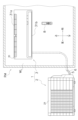
- FIG. 1 is a diagram showing the overall configuration of an air conditioner 1.
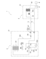
- FIG. 1 is a conceptual diagram of an air conditioner 1.
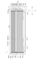
- FIG. 4 is a front view of the utilization unit 3;
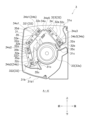
- FIG. FIG. 4 is a cross-sectional view of the utilization unit 3 taken along line A-A' in FIG. 3;
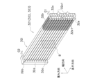
- 3 is a perspective view of a first heat utilization heat exchange part 321.
- FIG. It is the figure which looked at the 1st utilization heat exchange part 321 along the thickness direction of the flat tube 32a.
- 6 is an enlarged cross-sectional view of the first heat-utilizing heat exchange part 321 cut along a plane B in FIG. 5.
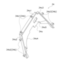
- FIG. 4 is a perspective view of a first member 34;
- FIG. 4 is a perspective view of a second member 35;
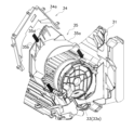
- FIG. 4 is an exploded perspective view showing how to assemble the first member 34 and the second member 35 to the second casing 31.
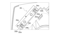
- FIG. 10 is an enlarged cross-sectional view of a heat-utilizing heat exchanger 32 and its surroundings of the air conditioner 1 according to Modification A.
- FIG. 10 is an enlarged cross-sectional view of a heat-utilizing heat exchanger 32 and its surroundings of the air conditioner 1 according to Modification A.
- the heat exchange unit according to the present disclosure is used, for example, as a utilization unit of an air conditioner that utilizes a vapor compression refrigeration cycle, although its application is not limited.
- the air conditioner 1 in which the utilization unit 3, which is an example of the heat exchange unit of the present disclosure, is used will be described with reference to the drawings.
- the air conditioner 1 air-conditions the inside (indoor) of the room RM, which is the target space, using a vapor compression refrigeration cycle.
- the air conditioner 1 mainly includes a heat source unit 2 , a utilization unit 3 , a liquid refrigerant communication pipe 5 , a gas refrigerant communication pipe 6 , a remote control 8 and a control section 9 .
- the liquid refrigerant communication pipe 5 and the gas refrigerant communication pipe 6 connect the heat source unit 2 and the utilization unit 3 .
- the heat source unit 2 , the utilization unit 3 , the liquid refrigerant communication pipe 5 , and the gas refrigerant communication pipe 6 are annularly connected by refrigerant pipes to form a refrigerant circuit 100 .
- Refrigerant circuit 100 has a refrigerant sealed therein.
- the control unit 9 controls each device of the air conditioner 1 to perform air conditioning operations such as heating operation and cooling operation.
- FIG. 1 is a diagram showing the overall configuration of the air conditioner 1.
- FIG. FIG. 2 is a conceptual diagram of the air conditioner 1. As shown in FIG. The directions of up, down, front, rear, left and right used in the following description follow the directions indicated by the arrows in FIGS.
- the heat source unit 2 is installed outside the room RM (outside the room, for example, on the roof of the building, near the outer wall of the building, etc.).
- the heat source unit 2 mainly includes a first casing 21, a compressor 22, a four-way switching valve 23, a heat source heat exchanger 24, a heat source expansion valve 25, a heat source fan 26, and a closing valve 27. ing.
- the first casing 21 is a substantially rectangular parallelepiped housing.
- the first casing 21 accommodates a compressor 22, a four-way switching valve 23, a heat source heat exchanger 24, a heat source expansion valve 25, and a heat source fan 26 inside.
- the compressor 22 sucks low-pressure refrigerant from the suction side 22a, compresses it to a high pressure, and then discharges it from the discharge side 22b.
- the compressor 22 has a compression element (not shown) and a compressor motor (not shown) that rotationally drives the compression element.
- the rotation speed of the compressor motor is controlled by the controller 9 via an inverter or the like.
- the capacity of the compressor 22 is controlled by the controller 9 changing the rotation speed of the compressor motor.
- the four-way switching valve 23 switches the direction of refrigerant flow in the refrigerant circuit 100 .
- the four-way switching valve 23 has a first port P1, a second port P2, a third port P3, and a fourth port P4.
- the four-way switching valve 23 is controlled by the controller 9 to be in the first state (the state indicated by the dashed line in FIG. 2) in which the first port P1 and the fourth port P4 communicate with each other and the second port P2 and the third port P3 communicate with each other. ) and a second state (shown by a solid line in FIG. 2) in which the first port P1 and the second port P2 communicate with each other and the third port P3 and the fourth port P4 communicate with each other.
- the first port P1 is connected to the discharge side 22b of the compressor 22.
- the second port P2 is connected to the gas side of the heat source heat exchanger 24 .
- the third port P3 is connected to the suction side 22a of the compressor 22 .
- the fourth port P4 is connected to the gas refrigerant communication pipe 6 .
- the heat source heat exchanger 24 is a heat exchanger that exchanges heat between the refrigerant and the outside air. One end of the heat source heat exchanger 24 is connected to the heat source expansion valve 25 . The other end of the heat source heat exchanger 24 is connected to the second port P2 of the four-way switching valve 23 .
- the heat source expansion valve 25 is an expansion mechanism that reduces the pressure of the refrigerant in the refrigerant circuit 100 .
- the heat source expansion valve 25 is provided between the liquid refrigerant communication pipe 5 and the liquid side of the heat source heat exchanger 24 .
- the heat source expansion valve 25 is an electric expansion valve whose degree of opening can be controlled. The degree of opening of the heat source expansion valve 25 is controlled by the controller 9 .
- the heat source fan 26 generates airflow and sends outside air to the heat source heat exchanger 24 .
- the heat source fan 26 sends outside air to the heat source heat exchanger 24, thereby promoting heat exchange between the refrigerant in the heat source heat exchanger 24 and the outside air.
- the heat source fan 26 is rotationally driven by a heat source fan motor 26a.
- the air volume of the heat source fan 26 is controlled by the controller 9 changing the rotation speed of the heat source fan motor 26a.
- the closing valve 27 is a valve that is manually opened and closed, and is opened and closed by an installation worker when installing the air conditioner 1, for example.
- the closing valve 27 includes a liquid side closing valve 27a and a gas side closing valve 27b.
- the liquid-side closing valve 27 a is provided between the heat source expansion valve 25 and the liquid refrigerant communication pipe 5 in the refrigerant circuit 100 .
- the gas side shutoff valve 27 b is provided between the fourth port P ⁇ b>4 of the four-way switching valve 23 and the gas refrigerant communication pipe 6 in the refrigerant circuit 100 .
- the usage unit 3 is a wall-mounted indoor air conditioner installed on the wall WL in the room RM.
- the utilization unit 3 mainly has a second casing 31 , three utilization heat exchangers 32 , a utilization fan 33 , two first members 34 and two second members 35 .
- FIG. 3 is a front view of the usage unit 3.
- FIG. FIG. 4 is a cross-sectional view of the user unit 3 taken along line A-A' in FIG.
- FIG. 3 shows the inside of the second casing 31 through part of the second casing 31 .
- FIG. 4 shows the protrusion 34b (described later) of the first member 34 in a see-through manner.
- the second casing 31 is a substantially rectangular parallelepiped housing elongated in the left-right direction.
- the second casing 31 accommodates the utilization heat exchanger 32, the utilization fan 33, the first member 34, and the second member 35 inside.
- the second casing 31 has an inlet 31a, an outlet 31b, and an opening 31c.
- the second casing 31 is an example of a casing.
- the inflow port 31 a is an opening that allows indoor air to flow into the second casing 31 .
- the inlet 31 a is formed in the upper part of the front surface of the second casing 31 .
- the blowout port 31b is an opening through which the air that has undergone heat exchange with the refrigerant in the heat utilization heat exchanger 32 blows out.
- the blowout port 31b is formed in the lower portion of the front surface of the second casing 31 .
- the outlet 31b is closed by a flap 31b1.
- the attitude (rotational angle) of the flap 31b1 is controlled by the controller 9 .
- the control unit 9 controls the posture of the flap 31b1 to adjust the opening of the blower outlet 31b.
- the opening 31c is an opening for engaging a first fixing portion 35c (described later) of the second member 35.
- the second members 35 are provided in the vicinity of both ends of the heat utilization heat exchanger 32 in the left-right direction.
- Each second member 35 also has two first fixing portions 35c. Therefore, two openings 31c are also formed near both ends of the heat exchanger 32 in the left-right direction.
- the utilization fan 33 generates airflow.
- the indoor air passes through the utilization heat exchanger 32 by the utilization fan 33 generating an airflow. Passing the indoor air through the heat exchanger 32 promotes heat exchange between the refrigerant in the heat exchanger 32 and the outside air.
- the utilization fan 33 is a cross-flow fan whose rotation axis is arranged along the left-right direction.
- the utilization fan 33 is rotationally driven by a utilization fan motor 33a.
- the air volume of the utilization fan 33 is controlled by the controller 9 changing the rotational speed of the utilization fan motor 33a.
- the utilization heat exchanger 32 exchanges heat between the refrigerant and the indoor air in the refrigerant circuit 100 .
- One end of the utilization heat exchanger 32 is connected to the liquid refrigerant communication pipe 5 .
- the other end of the utilization heat exchanger 32 is connected to the gas refrigerant communication pipe 6 .
- the utilization heat exchanger 32 is an example of a heat exchanger.
- the utilization heat exchanger 32 is composed of three utilization heat exchange units: a first utilization heat exchange unit 321 , a second utilization heat exchange unit 322 , and a third utilization heat exchange unit 323 .
- the difference between the first heat utilization unit 321 , the second heat utilization unit 322 , and the third heat utilization unit 323 is the arrangement inside the second casing 31 .
- the first heat utilization section 321, the second heat utilization section 322, and the third heat utilization section 323 have the same structure. For this reason, the structure of the first heat-utilization exchange unit 321 will be described below as an example, and descriptions of the structures of the second heat-utilization heat-exchange unit 322 and the third heat-utilization heat exchange unit 323 will be omitted.
- the arrangement of the first heat utilization unit 321, the second heat utilization unit 322, and the third heat utilization unit 323 inside the second casing 31 will be described later.
- the first heat utilization unit 321, the second heat utilization unit 322, and the third heat utilization unit 323 are collectively referred to as heat utilization units 321, 322, and 323.
- the utilization heat exchange units 321, 322, and 323 are an example of a first heat exchange unit.
- the first heat utilization section 321 and the third heat utilization section 323 are examples of a second heat exchange section.
- FIG. 5 is a perspective view of the first utilization heat exchange section 321.
- FIG. FIG. 6 is an enlarged cross-sectional view of the first heat-utilizing heat exchange section 321 cut along a plane B in FIG.
- FIG. 7 is a diagram of the first heat-utilizing heat exchange section 321 viewed along the thickness direction of the flat tube 32a.
- FIG. 7 also shows a portion of the first member 34 for convenience.
- the thickness direction, width direction, and longitudinal direction of the flat tube 32a used in the following description follow directions indicated by arrows in FIGS.
- the first utilization heat exchange section 321 has a plurality of flat tubes 32a, a plurality of heat transfer fins 32b, a first header 32c, a second header 32d, and a third header 32e.
- the first utilization heat exchange section 321 is a laminated heat exchanger in which a plurality of flat tubes 32a are laminated with a predetermined interval in the thickness direction of the flat tubes 32a by a plurality of heat transfer fins 32b.
- the heat-utilizing heat exchanger 32 has an inner-utilizing heat-exchanging portion 32i and an outer-utilizing heat-exchanging portion 32o.
- the flat tube 32a is a heat transfer tube through which a refrigerant flows.
- the flattened tube 32a is formed in an oval shape with a flattened cross section.
- the flat tube 32a is a multi-hole tube having a plurality of coolant channels 32a1 formed perpendicular to the cross section.
- the plurality of coolant channels 32a1 are formed side by side in the width direction of the flat tube 32a.
- the flat tube 32a is formed, for example, by extrusion using aluminum or an aluminum alloy. In this embodiment, the flat tube 32a is arranged so that the longitudinal direction extends along the left-right direction.
- the heat transfer fins 32b are strip-shaped plate members that support a plurality of flat tubes 32a at predetermined intervals.
- the heat transfer fins 32b are formed with a plurality of slit-like notches 32b1 for inserting the flat tubes 32a.
- the notch 32b1 is formed so as to extend from one edge extending in the longitudinal direction of the heat transfer fin 32b toward the other edge while being orthogonal to the edge when viewed from the thickness direction of the heat transfer fin 32b.
- the plurality of cutouts 32b1 are formed at predetermined intervals in the longitudinal direction of the heat transfer fins 32b.
- the heat transfer fins 32b are made of, for example, aluminum or an aluminum alloy.
- the flat tube 32a is inserted into the notch 32b1 with the width direction along the extending direction of the notch 32b1 of the heat transfer fins 32b.
- the plurality of heat transfer fins 32b are arranged at predetermined intervals in the longitudinal direction of the flat tube 32a.
- the heat transfer fins 32b and the flat tubes 32a are joined by brazing at the notches 32b1.
- the plurality of flat tubes 32a are joined to the heat transfer fins 32b so that their ends are aligned along the thickness direction of the flat tubes 32a.
- 5 and 7 illustrate, for convenience, the outer edge formed by the plurality of heat transfer fins 32b arranged in the longitudinal direction of the flat tube 32a and part of the plurality of heat transfer fins 32b.
- Both the inner-use heat exchange section 32i and the outer-use heat exchange section 32o are formed in substantially the same shape by joining a predetermined number of flat tubes 32a to a predetermined number of heat transfer fins 32b.
- the inner-use heat exchange portion 32i and the outer-use heat exchange portion 32o are arranged to overlap each other in the thickness direction of the flat tube 32a. Thereby, as indicated by arrows in FIG. A channel is formed in which the airflow generated by 33 flows.
- the inner-use heat exchange section 32i is arranged at a position closer to the use fan 33 than the outer-use heat exchange section 32o.
- the first header 32c, the second header 32d, and the third header 32e are cylindrical members that connect the refrigerant flow paths 32a1 of the flat tubes 32a at the ends of the flat tubes 32a.
- the first header 32c is provided at one end in the longitudinal direction of the flat tubes 32a of the inside-use heat exchange section 32i so as to communicate the refrigerant flow paths 32a1 of the plurality of flat tubes 32a with each other. Specifically, one end in the longitudinal direction of the plurality of flat tubes 32a included in the inside-use heat exchange section 32i is inserted into the first header 32c through an opening formed in the side surface of the first header 32c, and brazed or the like is used. is fixed to the first header 32c.
- first header 32c Between the first header 32c and the heat transfer fins 32b of the inner heat exchange portion 32i adjacent to the first header 32c, there is formed a gap G1 having a predetermined width into which the projecting portion 34b (described later) of the first member 34 can be inserted. It is fixed to the flat tube 32a so as to be The first header 32c is connected to the liquid refrigerant communication pipe 5 via a branch pipe 32c1.
- the second header 32d is arranged at the other longitudinal end of the flat tube 32a of the inner heat exchange section 32i and the other longitudinal end of the outer heat exchange section 32o of the inner heat exchange section 32i.
- Refrigerant passages 32a1 of the plurality of flat tubes 32a and refrigerant passages 32a1 of the plurality of flat tubes 32a of the outside heat exchange section 32o are provided so as to communicate with each other.
- the other longitudinal end of the flat tubes 32a of the heat exchange section 32i for internal use and the other end in the longitudinal direction of the flat tubes 32a of the heat exchange section 32o for external use are formed on the side surface of the second header 32d. It is inserted into the second header 32d through the opened opening and fixed to the second header 32d using brazing or the like.
- a gap G2 having a predetermined width into which the projecting portion 34b (described later) of the first member 34 can be inserted is formed. It is fixed to the flat tube 32a so as to be
- the third header 32e is provided at one end in the longitudinal direction of the flat tubes 32a of the outside-use heat exchange section 32o so as to communicate the refrigerant flow paths 32a1 of the plurality of flat tubes 32a. Specifically, one end in the longitudinal direction of the plurality of flat tubes 32a included in the outside-use heat exchange section 32o is inserted into the third header 32e through an opening formed in the side surface of the third header 32e, and brazed or the like is used. is fixed to the third header 32e.
- the third header 32e is connected to the gas refrigerant communication pipe 6 via a branch pipe 32e1.
- the refrigerant that has flowed into the first header 32c through the liquid refrigerant communication pipe 5 passes through the plurality of refrigerant flow paths 32a1 formed in the flat tubes 32a of the inner heat exchange portion 32i and into the third header 32e. influx.
- the refrigerant that has flowed into the third header 32e passes through the plurality of refrigerant flow paths 32a1 formed in the outside heat exchange portion 32o, and flows into the gas refrigerant communication pipe 6 through the second header 32d.
- the refrigerant that has flowed into the first header 32c through the gas refrigerant communication pipe 6 passes through a plurality of refrigerant flow paths 32a1 formed in the flat tubes 32a of the outside heat exchange section 32o and flows into the third header 32e. do.
- the refrigerant that has flowed into the third header 32e passes through a plurality of refrigerant flow paths 32a1 formed in the inner heat exchange portion 32i, and flows into the liquid refrigerant communication pipe 5 through the first header 32c.
- the first header 32c, the second header 32d, and the third header 32e are collectively referred to as headers 32c, 32d, and 32e.
- the first utilization heat exchange section 321 is provided in front of the utilization fan 33 so that the thickness direction of the flat tube 32a is inclined forward with respect to the up-down direction (vertical direction) when the utilization unit 3 is viewed from the left-right direction.
- the second heat utilization unit 322 is provided above the first heat utilization heat exchange unit 321 when the utilization unit 3 is viewed from the left and right direction so that the thickness direction of the flat tube 32a is inclined rearward with respect to the vertical direction. .
- the third utilization heat exchange section 323 is provided behind and above the utilization fan 33 when the utilization unit 3 is viewed from the left-right direction so that the thickness direction of the flat tube 32a is inclined forward with respect to the vertical direction.
- the first member 34 is attached to the utilization heat exchanger 32, and while supporting the utilization heat exchanger 32, the utilization heat exchanger 32 is affected by vibrations, etc. due to the operation of the utilization unit 3. regulate the movement of
- the first member 34 is a plate-like member, and in the region surrounded by the outer circumference of the utilization fan 33 and the utilization heat exchanger 32, the left and right ends of the flat tube 32a of the utilization heat exchanger 32 are provided with respect to the left-right direction. are arranged perpendicular to each other.
- the first member 34 has a main body 34a and a protrusion 34b.
- the first member 34 is manufactured using hard resin.
- the state in which the first member 34 is attached to the utilization heat exchanger 32 refers to a state in which the protrusions 34b are inserted between the flat tubes 32a adjacent in the thickness direction.
- the usage unit 3 has two first members 34 .
- Each of the two first members 34 is arranged such that the main body 34 a faces the gap G ⁇ b>1 and the gap G ⁇ b>2 of the utilization heat exchanger 32 .
- the first member 34 is used vertically below the first heat utilization section 321 and the third heat utilization section 323 of the utilization heat exchanger 32 and behind the second heat utilization section 322. It is attached to the heat exchanger 32 .
- FIG. 8 is a perspective view of the first member 34.
- the body 34a mainly has a first cross section 34a1, a second cross section 34a2, a third cross section 34a3 and a fourth cross section 34a4. is a member of
- the first cross section 34a1 contacts the end of the heat transfer fin 32b of the inner heat exchange part 32i of the first heat utilization heat exchange part 321. , the surface formed so as to face the gap G1 or the gap G2 of the flat tube 32a.
- the second cross section 34a2 abuts on the end of the heat transfer fin 32b of the inner heat exchange part 32i of the second heat utilization heat exchange part 322. , the surface formed so as to face the gap G1 or the gap G2 of the flat tube 32a.
- the third cross section 34a3 abuts on the end of the heat transfer fin 32b of the inner heat exchange part 32i of the third heat utilization heat exchange part 323. , the surface formed so as to face the gap G1 or the gap G2 of the flat tube 32a.
- the fourth cross section 34a4 is a surface formed so as to be located outside both ends of the utilization fan 33 in the left-right direction.
- the fourth cross section 34a4 is formed so as to abut on a main body 35a (described later) of the second member 35. As shown in FIG.
- the opening 34a5 is an opening for engaging a second fixing portion 35d (described later) of the second member 35.
- the projecting portion 34b is configured such that each of the first cross section 34a1, the second cross section 34a2, and the third cross section 34a3 abuts on the flat tubes 32a of the inner heat exchange section 32i, and the flat tubes 32a adjacent to each other in the gap G1 or the gap G2. inserted between The protrusion 34b is a columnar protrusion.
- the protrusion 34b has a first protrusion 34b1, a second protrusion 34b2, and a third protrusion 34b3.
- the first projecting portion 34b1 is inserted between the adjacent flat tubes 32a in the gap G1 or gap G2 of the inner heat exchange portion 32i that contacts the first cross section 34a1.
- the first protrusion 34b1 is formed to protrude from the first cross section 34a1.
- the second projecting portion 34b2 is inserted between the adjacent flat tubes 32a in the gap G1 or the gap G2 of the inner heat exchange portion 32i that contacts the second cross section 34a2.
- the second protrusion 34b2 is formed to protrude from the second cross section 34a2.
- the third projecting portion 34b3 is inserted between the adjacent flat tubes 32a in the gap G1 or gap G2 of the inner heat exchange portion 32i that contacts the third cross section 34a3.
- the third protrusion 34b3 is formed to protrude from the third cross section 34a3.
- the first member 34 provided on the left side of the heat exchanger 32 has three first projections 34b1, three second projections 34b2, and three third projections 34b3.
- the first member 34 provided on the right side of the heat exchanger 32 has two first projections 34b1, two second projections 34b2, and two third projections 34b3.
- the numbers of the first protrusions 34b1, the second protrusions 34b2, and the third protrusions 34b3 are not limited to two and three, and may be one or four or more.
- the number of the first protrusions 34b1, the second protrusions 34b2, and the third protrusions 34b3 of the first member 34 may be the same on the left side and the right side of the heat exchanger 32, It does not have to be the same number.
- the projections 34b of the first member 34 are inserted between the adjacent flat tubes 32a in the gaps G1 or G2 of the inner heat exchange portions 32i, so that the flat tubes 32a It restricts movement of the utilization heat exchanger 32 in the thickness direction or the longitudinal direction.
- the main body 34a (specifically, the first cross section 34a1, the second cross section 34a2, and the third cross section 34a3) is configured for the inside utilization heat exchange.
- the heat exchanger 32 is supported by contacting the ends of the heat transfer fins 32b of the portion 32i.
- the second member 35 is fixed to both the second casing 31 and the first member 34, and supports the utilization heat exchanger 32 via the first member 34. do.
- the second member 35 has a main body 35a, an insertion portion 35b, two first fixing portions 35c, and a second fixing portion 35d.
- the usage unit 3 has two second members 35 .
- the two second members 35 are arranged to support the first member 34 arranged on the right side of the utilization heat exchanger 32 and the first member 34 arranged on the left side of the utilization heat exchanger 32 respectively. .
- FIG. 9 is a perspective view of the second member 35.
- FIG. 10 is an exploded perspective view showing how to assemble the first member 34 and the second member 35 to the second casing 31.
- FIG. 10 is an exploded perspective view showing how to assemble the first member 34 and the second member 35 to the second casing 31.
- the main body 35a is an arc-shaped plate member that partially covers the upper portion of the utilization fan 33 when viewed from the left and right direction.
- the main body 35a is formed so as to contact the fourth cross section 34a4 of the first member 34. As shown in FIG.
- the insertion portion 35b restricts movement of the first member 34 in the left-right direction.
- the insertion portion 35b is configured by a plate-like member protruding from the main body 35a so as to be orthogonal to the left-right direction.
- the plate-like members forming the insertion portion 35b are provided with a gap of a predetermined width in the left-right direction so as to sandwich the main body 34a of the first member 34 in the left-right direction.
- the first member 34 as shown in FIG. 10, is inserted into the gap formed by the main body 34a and the insertion portion 35b.
- the first fixing portion 35 c fixes the second member 35 to the second casing 31 .
- the first fixing portion 35c is a claw that engages with the opening 31c of the second casing 31 .
- the first fixing portion 35c is formed so as to protrude downward from the circumferential end portion of the main body 35a when viewed in the left-right direction. As shown in FIGS. 10 and 4, by covering the top of the utilization fan 33 with the main body 35a, the first fixing portion 35c engages with the opening 31c. By engaging the first fixing portion 35 c with the opening 31 c , the vertical movement of the second member 35 is restricted and the second member 35 is fixed to the second casing 31 .
- the second fixing part 35 d fixes the first member 34 to the second member 35 .
- the second fixing portion 35d is a claw that engages with the opening 34a5 of the first member 34. As shown in FIG. As shown in FIG. 10, the second fixing portion 35d is engaged with the opening 34a5 by inserting the first member 34 into the insertion portion 35b. By engaging the second fixing portion 35d with the opening 34a5, the first member 34 is fixed to the second member 35, and the vertical movement of the first member 34 is restricted.
- the second member 35 is A utilization heat exchanger 32 can be supported via one member 34 .
- the second member 35 also has a function of flowing the condensed water generated in the heat utilization heat exchanger 32 to drain pans (not shown) provided below the second member 35 before and after the utilization fan 33 respectively. Specifically, when the condensed water generated in the heat exchanger 32 drops from the end of the heat exchanger 32 to the main body 35a, it moves along the upper surface of the main body 35a toward the front end or the rear end. and drop into the drain pan.
- the remote controller 8 receives instructions from the user to perform heating operation, cooling operation, humidification operation, etc., instructions to stop the air conditioner 1, and set values such as the set temperature Ts, and controls the received results. It is transmitted to the control unit 9 as a signal.
- control unit 9 mainly transmits and receives control signals to the compressor 22, the four-way switching valve 23, the heat source expansion valve 25, the heat source fan 26, the utilization fan 33, and the remote controller 8. connected as possible. Although the details will be described later, the control unit 9 controls the operation of the compressor 22, the four-way switching valve 23, the heat source expansion valve 25, the heat source fan 26, and the utilization fan 33, thereby operating the refrigerant circuit 100. Control.
- the control unit 9 is typically realized by a computer including a control arithmetic device and a storage device (both not shown).
- the control computing unit is a processor, such as a CPU or GPU.
- the control arithmetic unit reads out the control program stored in the storage device and performs operation control according to this control program. Furthermore, the control arithmetic device can write the arithmetic result to the storage device and read the information stored in the storage device according to the control program.
- FIG. 2 is a schematic diagram.
- the control unit 9 is composed of an outdoor control unit provided inside the heat source unit 2 and an indoor control unit provided inside the utilization unit 3, and the outdoor control unit and the indoor control unit exchange control signals with each other. It may be connected by a possible communication line.
- control unit 9 When the control unit 9 receives a control signal from the remote control 8 instructing the execution of the heating operation, it starts the heating operation. During the heating operation, the control unit 9 switches the four-way selector valve 23 to the first state (see broken line in FIG. 2). Furthermore, the control unit 9 sets the heat source expansion valve 25 to the degree of opening corresponding to the set temperature Ts received from the remote controller 8 , operates the compressor 22 , and drives the utilization fan 33 to rotate. As a result, the heat source heat exchanger 24 functions as a refrigerant evaporator, and the utilization heat exchanger 32 functions as a refrigerant condenser.
- the refrigerant circuit 100 functions as follows.
- the high-pressure refrigerant discharged from the compressor 22 exchanges heat with the indoor air sent by the utilization fan 33 in the utilization heat exchanger 32 and is condensed.
- the indoor air is heated and discharged indoors as conditioned air.
- the condensed refrigerant passes through the heat source expansion valve 25 and is decompressed, it evaporates in the heat source heat exchanger 24 by exchanging heat with outside air sent by the heat source fan 26 .
- the refrigerant that has passed through the heat source heat exchanger 24 is sucked into the compressor 22 and compressed.
- the controller 9 receives a control signal from the remote controller 8 instructing the execution of the cooling operation, it starts the cooling operation.
- the controller 9 switches the four-way selector valve 23 to the second state (see the solid line in FIG. 1).
- the control unit 9 sets the heat source expansion valve 25 to the degree of opening corresponding to the set temperature Ts received from the remote controller 8 , operates the compressor 22 , and drives the utilization fan 33 to rotate.
- the heat source heat exchanger 24 functions as a refrigerant condenser
- the utilization heat exchanger 32 functions as a refrigerant evaporator.
- the refrigerant circuit 100 functions as follows.
- the high-pressure refrigerant discharged from the compressor 22 exchanges heat with outside air sent by the heat source fan 26 in the heat source heat exchanger 24 and is condensed.
- the indoor air is cooled and discharged indoors as conditioned air.
- the refrigerant that has passed through the utilization heat exchanger 32 is sucked into the compressor 22 and compressed.
- the utilization unit 3 includes a utilization heat exchanger 32 , a first member 34 and a second member 35 .
- the utilization heat exchanger 32 is formed by stacking a plurality of flat tubes 32a with heat transfer fins 32b at predetermined intervals in the thickness direction.
- the first member 34 is attached to the utilization heat exchanger 32 .
- the second member 35 supports the utilization heat exchanger 32 via the first member 34 .
- the first member 34 has a body 34a and a projection 34b projecting from the body 34a. The projecting portion 34b is inserted between the adjacent flat tubes 32a.
- the protrusion 34b of the first member 34 is inserted between the adjacent flat tubes 32a, thereby restricting movement of the utilization heat exchanger 32 in the thickness direction or longitudinal direction of the flat tubes 32a. be done.
- the member the first member 34
- the member can be greatly reduced. Therefore, even if the first member 34 and the flat tube 32a slide due to vibration or the like due to the operation of the usage unit 3, damage to the flat tube 32a due to this sliding is suppressed.
- the choice of materials that can be used for the flat tube 32a increases, and the manufacturing cost of the utilization unit 3 is suppressed.
- the first member 34 has a plurality of protrusions 34b.
- the utilization unit 3 including the utilization heat exchanger 32 including a plurality of heat exchange units first utilization heat exchange unit 321, second utilization heat exchange unit 322, and third utilization heat exchange unit 323)
- the first member 34 is , a plurality of projecting portions 34b are provided for each of the utilization heat exchange portions 321, 322, and 323. As shown in FIG.
- the movement of the utilization heat exchanger 32 in the thickness direction or longitudinal direction of the flat tube 32a is effectively restricted by the first member 34 having the plurality of protrusions 34b.
- the projecting portion 34b is columnar.
- the projecting portion 34b By forming the projecting portion 34b into a columnar shape, it becomes possible to easily insert the projecting portion 34b between the adjacent flat tubes 32a. Therefore, the manufacturing of the usage unit 3 is facilitated, and the manufacturing cost of the usage unit 3 is suppressed.
- the first member 34 is manufactured using resin.
- the hardness of the protrusion 34b can be reduced compared to the case of manufacturing using metal. Therefore, even if the first member 34 and the flat tube 32a slide, damage to the flat tube 32a due to this sliding is suppressed. As a result, the choice of materials that can be used for the flat tube 32a increases, and the manufacturing cost of the utilization unit 3 is suppressed.
- the utilization unit 3 further has a second casing 31 and a second member 35 fixed to the second casing 31 .
- the first member 34 is fixed relative to the second member 35 by engagement.
- the first cross section 34a1, the second cross section 34a2, and the third cross section 34a3 of the main body 34a correspond to the inner heat exchange portion 32i. It is formed so as to abut on the end portion of the heat transfer fin 32b.
- the first member 34 is configured such that the first section 34a1, the second section 34a2, and the third section 34a3 of the main body 34a abut against the heat transfer fins 32b of the inner heat-exchanging portion 32i. It can take 32 weights.
- the weight of the utilization heat exchanger 32 received by the protruding portion 34b is reduced to substantially zero or significantly reduced. is suppressed from being damaged.
- the number of options for the flat tube 32a that can be used increases, and the manufacturing cost of the utilization unit 3 is suppressed.
- the utilization heat exchanger 32 has a first utilization heat exchange section 321 and a third utilization heat exchange section 323 in which the thickness direction of the flat tubes 32a is inclined with respect to the vertical direction when viewed from the left-right direction.
- the first member 34 is attached to the heat utilization part 321 vertically below the first heat utilization part 321 and the third heat utilization part 323 .
- the first member 34 supports the first heat utilization part 321 and the third heat utilization part 323 while supporting the first heat utilization part 321 and the third heat utilization part 323 .
- movement can be regulated.
- the projecting portion 34b may have a claw portion 34c that engages with the flat tube 32a.
- the protruding portions 34b of the claw portions 34c are inserted between the adjacent flat tubes 32a so as to engage with the ends of the flat tubes 32a of the inner heat exchange portion 32i on the side of the outer heat exchange portion 32o. formed in
- FIG. 11 is an enlarged cross-sectional view of the heat utilization heat exchanger 32 and its surroundings of the air conditioner 1 according to Modification A. As shown in FIG.
- the first member 34 By engaging the claw portion 34c with the end portion of the flat tube 32a, the first member 34 can effectively restrict the movement of the utilization heat exchanger 32.
- the first member 34 may be manufactured using materials other than resin.
- the first member 34 may be manufactured using metal, and a resin coating may be applied to the surface.
- the first member 34 may be made of metal and may have insulating rubber attached to its surface.
- the hardness of the surface of the first member 34 is kept low by the resin coating or the insulating rubber, thereby effectively suppressing damage to the flat tube 32a due to sliding, while ensuring high rigidity of the first member 34.
- the first member 34 is fixed to the second member 35 by engaging the second fixing portion 35d with the opening 34a5 of the first member 34, but the fixing method is not limited to this.
- the first member 34 may be fixed to the second member 35 by screwing.
- the main body 34a of the first member 34 may be in contact with any one of the headers 32c, 32d, and 32e.
- the first member 34 By contacting the body 34a of the first member 34 with any one of the headers 32c, 32d, 32e, the first member 34 is configured to utilize the heat exchanger by contacting the body 34a with one of the headers 32c, 32d, 32e. It can take 32 weights. This reduces the weight of the heat utilization heat exchanger 32 that the protrusion 34b receives. As a result, the weight of the utilization heat exchanger 32 received by the protruding portion 34b is reduced to substantially zero or significantly reduced. is suppressed from being damaged. As a result, the number of options for the flat tube 32a that can be used increases, and the manufacturing cost of the utilization unit 3 is suppressed.
- the utilization heat exchanger 32 has a plurality of utilization heat exchange sections 321, 322, and 323, but the utilization heat exchanger 32 may be configured with only one heat exchange section.
- the heat source unit 2 may include the first member attached to the heat source heat exchanger 24 .
Landscapes
- Engineering & Computer Science (AREA)
- Physics & Mathematics (AREA)
- Mechanical Engineering (AREA)
- General Engineering & Computer Science (AREA)
- Thermal Sciences (AREA)
- Chemical & Material Sciences (AREA)
- Combustion & Propulsion (AREA)
- Geometry (AREA)
- Heat-Exchange Devices With Radiators And Conduit Assemblies (AREA)
- Air Filters, Heat-Exchange Apparatuses, And Housings Of Air-Conditioning Units (AREA)
Abstract
Description
本開示に係る熱交換ユニットは、用途を限定するものではないが、例えば、蒸気圧縮式の冷凍サイクルを利用する空気調和装置の利用ユニットに用いられる。以下では、本開示の熱交換ユニットの一例である利用ユニット3が使用される空気調和装置1について、図面を参照しながら説明する。
(2-1)熱源ユニット
熱源ユニット2は、部屋RMの外部(室外。例えば、建物の屋上や建物の外壁面近傍等。)に設置されている。熱源ユニット2は、主として、第1ケーシング21と、圧縮機22と、四路切換弁23と、熱源熱交換器24と、熱源膨張弁25と、熱源ファン26と、閉鎖弁27とを有している。
第1ケーシング21は、略直方体形状の筐体である。第1ケーシング21は、圧縮機22と、四路切換弁23と、熱源熱交換器24と、熱源膨張弁25と、熱源ファン26とを内部に収容する。
圧縮機22は、冷媒回路100において、低圧の冷媒を吸入側22aから吸入して、高圧になるまで圧縮した後、吐出側22bから吐出する。圧縮機22は、圧縮要素(図示省略)と、圧縮要素を回転駆動する圧縮機モータ(図示省略)を有する。圧縮機モータは、インバータ等を介して、制御部9により回転数が制御される。圧縮機22の容量は、制御部9が圧縮機モータの回転数を変えることにより制御される。
四路切換弁23は、冷媒回路100において、冷媒の流れの方向を切り換える。四路切換弁23は、第1ポートP1と、第2ポートP2と、第3ポートP3と、第4ポートP4と、を有する。四路切換弁23は、制御部9により、第1ポートP1と第4ポートP4が互いに連通して第2ポートP2と第3ポートP3が互いに連通する第1状態(図2において破線で示す状態)と、第1ポートP1と第2ポートP2が互いに連通して第3ポートP3と第4ポートP4が互いに連通する第2状態(図2において実線で示す状態)との間で切り換えられる。
熱源熱交換器24は、冷媒と外気との熱交換を行う熱交換器である。熱源熱交換器24の一端は、熱源膨張弁25に接続されている。熱源熱交換器24の他端は、四路切換弁23の第2ポートP2に接続されている。
熱源膨張弁25は、冷媒回路100において、冷媒を減圧する膨張機構である。熱源膨張弁25は、液冷媒連絡管5と、熱源熱交換器24の液側との間に設けられる。熱源膨張弁25は、開度制御が可能な電動膨張弁である。熱源膨張弁25の開度は、制御部9により制御される。
熱源ファン26は、気流を生成し、外気を熱源熱交換器24に送る。熱源ファン26が外気を熱源熱交換器24に送ることにより、熱源熱交換器24内の冷媒と外気との熱交換が促される。熱源ファン26は、熱源ファンモータ26aによって回転駆動される。熱源ファン26の風量は、制御部9が熱源ファンモータ26aの回転数を変えることにより制御される。
閉鎖弁27は、手動で開閉される弁であり、例えば、空気調和装置1の設置時等に設置作業者によって開閉される。閉鎖弁27は、液側閉鎖弁27aと、ガス側閉鎖弁27bとを含む。液側閉鎖弁27aは、冷媒回路100において、熱源膨張弁25と液冷媒連絡管5との間に設けられる。ガス側閉鎖弁27bは、冷媒回路100において、四路切換弁23の第4ポートP4とガス冷媒連絡管6との間に設けられる。
利用ユニット3は、部屋RMにおいて壁WLに掛けて設置される壁掛け型の室内空調機である。利用ユニット3は、主として、第2ケーシング31と、3つの利用熱交換器32と、利用ファン33と、2つの第1部材34と、2つの第2部材35とを有している。
第2ケーシング31は、左右方向に長い略直方体形状の筐体である。第2ケーシング31は、利用熱交換器32と、利用ファン33と、第1部材34と、第2部材35とを内部に収容する。第2ケーシング31は、流入口31aと、吹出口31bと、開口31cとを有する。
利用ファン33は、気流を生成する。利用ファン33が気流を生成することで、室内の空気が利用熱交換器32を通過する。室内の空気が利用熱交換器32を通過することにより、利用熱交換器32の冷媒と外気との熱交換が促される。利用ファン33は、回転軸が左右方向に沿って配置されたクロスフローファンである。
利用熱交換器32は、冷媒回路100において、冷媒と室内の空気との熱交換を行う。利用熱交換器32の一端は、液冷媒連絡管5に接続されている。利用熱交換器32の他端は、ガス冷媒連絡管6に接続されている。
第1部材34は、利用熱交換器32に装着され、利用熱交換器32を支持しながら、利用ユニット3の運転にともなう振動等による利用熱交換器32の動きを規制する。第1部材34は、板状の部材であって、利用ファン33の外周と利用熱交換器32とにより囲まれた領域において、利用熱交換器32の扁平管32aの左右両端に左右方向に対して直交するように配置される。第1部材34は、本体34aと、突起部34bとを有する。第1部材34は、硬質樹脂を用いて製造される。
第2部材35は、第2ケーシング31と第1部材34との両方に対して固定されており、第1部材34を介して利用熱交換器32を支持する。第2部材35は、本体35aと、挿入部35bと、2つの第1固定部35cと、第2固定部35dとを有する。
リモコン8は、ユーザーから暖房運転、冷房運転、及び加湿運転等の実行指示、空気調和装置1の停止指示、並びに設定温度Ts等の設定値を受け付け、受け付けた結果を制御信号として制御部9に送信する。
制御部9は、主に、圧縮機22と、四路切換弁23と、熱源膨張弁25と、熱源ファン26と、利用ファン33とリモコン8とに制御信号を送受信可能に接続されている。詳細は後述するが、制御部9は、圧縮機22と、四路切換弁23と、熱源膨張弁25と、熱源ファン26と、利用ファン33と、をそれぞれ運転制御することで冷媒回路100を制御する。
次に、制御部9が実行する空調運転である、暖房運転、及び冷房運転について説明する。
制御部9は、リモコン8から暖房運転の実行指示についての制御信号を受信すると暖房運転を開始する。暖房運転に際して、制御部9は、四路切換弁23を第1状態へ切り換える(図2の破線参照)。さらに、制御部9は、熱源膨張弁25を、リモコン8から受信した設定温度Tsに対応する開度とし、圧縮機22を運転し、利用ファン33を回転駆動する。これにより、熱源熱交換器24が冷媒の蒸発器として機能し、かつ、利用熱交換器32が冷媒の凝縮器として機能する。
制御部9は、リモコン8から冷房運転の実行指示についての制御信号を受信すると冷房運転を開始する。冷房運転に際して、制御部9は、四路切換弁23を第2状態へ切り換える(図1の実線参照)。さらに、制御部9は、熱源膨張弁25を、リモコン8から受信した設定温度Tsに対応する開度とし、圧縮機22を運転し、利用ファン33を回転駆動する。これにより、熱源熱交換器24が冷媒の凝縮器として機能し、かつ、利用熱交換器32が冷媒の蒸発器として機能する。
(4-1)
利用ユニット3は、利用熱交換器32と、第1部材34と、第2部材35とを備える。利用熱交換器32は、複数の扁平管32aが伝熱フィン32bによって厚み方向へ所定の間隔を空けて積層されている。第1部材34は、利用熱交換器32に装着される。第2部材35は、第1部材34を介して利用熱交換器32を支持する。第1部材34は、本体34a及び本体34aから突き出る突起部34bを有する。突起部34bは、隣り合う扁平管32aの間に挿入されている。
第1部材34は、突起部34bを複数有する。複数の熱交換部(第1利用熱交換部321、第2利用熱交換部322、及び第3利用熱交換部323)を含む利用熱交換器32を備える利用ユニット3では、第1部材34は、利用熱交換部321、322、323のそれぞれに対して複数の突起部34bを有する。
突起部34bは、柱状である。
第1部材34は、樹脂を用いて製造されている。
利用ユニット3は、第2ケーシング31と、第2ケーシング31に固定された第2部材35とをさらに有している。第1部材34は、係合により第2部材35に対して固定されている。
第1部材34は、本体34aが伝熱フィン32bに当接している。
利用熱交換器32は、左右方向から見て、扁平管32aの厚み方向が鉛直方向に対して傾斜した第1利用熱交換部321及び第3利用熱交換部323を有する。第1部材34は、第1利用熱交換部321及び第3利用熱交換部323の鉛直下方において利用熱交換部321に装着される。
(5-1)変形例A
突起部34bは、扁平管32aに係合する爪部34cを有していてもよい。爪部34cは、突起部34bが隣り合う扁平管32aの間に挿入されることにより、内側利用熱交換部32iの扁平管32aの、外側利用熱交換部32o側の端部に係合するように形成される。
第1部材34は、樹脂以外を用いて製造されてもよい。第1部材34は、金属を用いて製造され、樹脂コーティングが表面に施されてもよい。また、第1部材34は、金属を用いて製造され、絶縁ゴムが表面に取り付けられていてもよい。
上記実施形態では、第2固定部35dが第1部材34の開口34a5に係合することにより、第1部材34が第2部材35に対して固定されたが、固定方法はこれに限定されない。例えば、第1部材34は、ビス止めにより第2部材35に対して固定されてもよい。
第1部材34は、本体34aがヘッダ32c、32d、32eのいずれかに当接していてもよい。
上記実施形態では、利用熱交換器32は複数の利用熱交換部321、322、323を有していたが、利用熱交換器32は1つの熱交換部だけにより構成されてもよい。
以上では、第2ケーシング31とは別の第2部材35が第1部材34を介して利用熱交換器32を支持する例を実施形態として説明したが、第2ケーシング31が第2部材であってもよい。言い換えると、第2ケーシング31が第2部材として機能することで、第1部材34を支持してもよい。
以上では、第1部材34を備える利用ユニット3を実施形態として説明をしたが、熱源ユニット2が熱源熱交換器24に装着される第1部材を備えていてもよい。
100 冷媒回路
2 熱源ユニット
3 利用ユニット
31 第2ケーシング(ケーシング)
32 利用熱交換器
321 第1利用熱交換部
322 第2利用熱交換部
323 第3利用熱交換部
32a 扁平管
32b 伝熱フィン
32c 第1ヘッダ
32d 第2ヘッダ
32e 第3ヘッダ
33 利用ファン
34 第1部材
34a 本体
34b 突起部
34c 爪部
35 第2部材
Claims (12)
- 複数の扁平管(32a)が伝熱フィン(32b)によって厚み方向へ所定の間隔を空けて積層された熱交換器(32)と、
前記熱交換器に装着され、前記熱交換器の動きを規制する第1部材(34)と
を備え、
前記第1部材は、
本体(34a)及び前記本体から突き出る突起部(34b)を有し、前記突起部が隣り合う前記扁平管の間に挿入されている、
熱交換ユニット。 - 前記第1部材は、
前記突起部を複数有する、
請求項1に記載の熱交換ユニット。 - 前記熱交換器は、
複数の第1熱交換部(321、322、323)を含み、
前記第1部材は、
複数の前記第1熱交換部のそれぞれに対して複数の前記突起部を有する、
請求項1又は2に記載の熱交換ユニット。 - 前記突起部は、
柱状である、
請求項1から3のいずれか1項に記載の熱交換ユニット。 - 前記突起部は、
前記扁平管に係合する爪部(34c)を有する、
請求項1から3のいずれか1項に記載の熱交換ユニット。 - 前記第1部材は、
樹脂を用いて製造されている、
請求項1から5のいずれか1項に記載の熱交換ユニット。 - 前記第1部材は、
金属を用いて製造され、樹脂コーティングが表面に施されている、
請求項1から5のいずれか1項に記載の熱交換ユニット。 - 前記第1部材は、
金属を用いて製造され、絶縁ゴムが表面に取り付けられている、
請求項1から5のいずれか1項に記載の熱交換ユニット。 - ケーシング(31)と、前記ケーシングに固定された第2部材(35)とをさらに備え、
前記第1部材は、
ビス止め又は係合により前記第2部材に対して固定されている、
請求項1から8のいずれか1項に記載の熱交換ユニット。 - 前記第1部材は、
前記本体が前記伝熱フィンに当接している、
請求項1から9のいずれか1項に記載の熱交換ユニット。 - 前記熱交換器は、
複数の前記扁平管の端部を互いに接続するヘッダ(32c、32d、32e)をさらに有し、
前記第1部材は、
前記本体が前記ヘッダに当接している、
請求項1から9のいずれか1項に記載の熱交換ユニット。 - 前記熱交換器は、
前記扁平管の前記厚み方向が鉛直方向に対して傾斜した第2熱交換部(321、323)を有し、
前記第1部材は、
前記第2熱交換部の鉛直下方において前記熱交換器に装着される、
請求項1から11のいずれか1項に記載の熱交換ユニット。
Priority Applications (3)
| Application Number | Priority Date | Filing Date | Title |
|---|---|---|---|
| EP22907321.8A EP4450880A4 (en) | 2021-12-13 | 2022-12-07 | HEAT EXCHANGER UNIT |
| CN202280080816.2A CN118355235A (zh) | 2021-12-13 | 2022-12-07 | 热交换单元 |
| US18/742,205 US20240328718A1 (en) | 2021-12-13 | 2024-06-13 | Heat exchange unit |
Applications Claiming Priority (2)
| Application Number | Priority Date | Filing Date | Title |
|---|---|---|---|
| JP2021-201887 | 2021-12-13 | ||
| JP2021201887A JP2023087481A (ja) | 2021-12-13 | 2021-12-13 | 熱交換ユニット |
Related Child Applications (1)
| Application Number | Title | Priority Date | Filing Date |
|---|---|---|---|
| US18/742,205 Continuation US20240328718A1 (en) | 2021-12-13 | 2024-06-13 | Heat exchange unit |
Publications (1)
| Publication Number | Publication Date |
|---|---|
| WO2023112794A1 true WO2023112794A1 (ja) | 2023-06-22 |
Family
ID=86774585
Family Applications (1)
| Application Number | Title | Priority Date | Filing Date |
|---|---|---|---|
| PCT/JP2022/045107 Ceased WO2023112794A1 (ja) | 2021-12-13 | 2022-12-07 | 熱交換ユニット |
Country Status (5)
| Country | Link |
|---|---|
| US (1) | US20240328718A1 (ja) |
| EP (1) | EP4450880A4 (ja) |
| JP (3) | JP2023087481A (ja) |
| CN (1) | CN118355235A (ja) |
| WO (1) | WO2023112794A1 (ja) |
Families Citing this family (1)
| Publication number | Priority date | Publication date | Assignee | Title |
|---|---|---|---|---|
| JP2023087481A (ja) * | 2021-12-13 | 2023-06-23 | ダイキン工業株式会社 | 熱交換ユニット |
Citations (6)
| Publication number | Priority date | Publication date | Assignee | Title |
|---|---|---|---|---|
| JPS6050379U (ja) * | 1983-09-14 | 1985-04-09 | 松下精工株式会社 | 空気調和機における熱交換器の固定装置 |
| JP2011162092A (ja) * | 2010-02-12 | 2011-08-25 | Calsonic Kansei Corp | 車両用熱交換器の保護装置 |
| JP2012072918A (ja) * | 2010-09-27 | 2012-04-12 | Mitsubishi Electric Corp | 空気調和機の室内機、及びこの室内機を備えた空気調和機 |
| JP2016133256A (ja) * | 2015-01-19 | 2016-07-25 | ダイキン工業株式会社 | 空気調和装置の熱交換ユニット |
| WO2018128035A1 (ja) | 2017-01-04 | 2018-07-12 | 日立ジョンソンコントロールズ空調株式会社 | 室外機、および冷凍サイクル装置 |
| US10605547B2 (en) * | 2015-05-06 | 2020-03-31 | Valeo Systemes Thermiques | Heat exchanger comprising a protective device |
Family Cites Families (21)
| Publication number | Priority date | Publication date | Assignee | Title |
|---|---|---|---|---|
| US3163208A (en) * | 1961-09-29 | 1964-12-29 | Gen Electric | Brace for finned tubes |
| JPS486028Y1 (ja) * | 1970-05-25 | 1973-02-15 | ||
| JPS5441745U (ja) * | 1977-08-29 | 1979-03-20 | ||
| US4231421A (en) * | 1978-12-01 | 1980-11-04 | Carrier Corporation | Wound fin heat exchanger support |
| US4538678A (en) * | 1982-07-29 | 1985-09-03 | Nisshin Chemical Industry Co., Ltd. | Heat exchanging device |
| JP3043025B2 (ja) * | 1990-02-01 | 2000-05-22 | 昭和アルミニウム株式会社 | 熱交換器 |
| JP2565703Y2 (ja) * | 1991-12-20 | 1998-03-18 | サンデン株式会社 | 熱交換器の取付金具組付構造 |
| JP2737549B2 (ja) * | 1992-07-08 | 1998-04-08 | ダイキン工業株式会社 | 空気調和装置の熱交換器 |
| EP0980504B1 (de) * | 1997-05-07 | 2002-09-18 | Volkswagen Aktiengesellschaft | Kühler in einem kraftfahrzeug mit einer schutzeinrichtung gegen auftreffende partikel |
| FR2804501B1 (fr) * | 2000-01-28 | 2002-04-12 | Valeo Thermique Moteur Sa | Module d'echange de chaleur, en particulier pour vehicule automobile |
| JP2002243388A (ja) * | 2001-02-16 | 2002-08-28 | Ebara Shinwa Ltd | 冷却塔用などの熱交換体の組立方法 |
| US20110073277A1 (en) * | 2008-07-23 | 2011-03-31 | Karl Andrew E | Adapter for heat exchanger |
| JP5663174B2 (ja) * | 2010-02-15 | 2015-02-04 | 日本パーカライジング株式会社 | 表面処理皮膜を有するアルミニウム又はアルミニウム合金材料及びその表面処理方法 |
| CN202083248U (zh) * | 2011-03-17 | 2011-12-21 | 冠昊有限公司 | 多通道式扁状蛇盘管热交换器及其热交换设备 |
| JP6222455B2 (ja) | 2012-12-28 | 2017-11-01 | パナソニックIpマネジメント株式会社 | 空気調和機 |
| CN203364650U (zh) | 2013-05-21 | 2013-12-25 | 苏州威尔博机械有限公司 | 旋翅片热交换器 |
| WO2014199490A1 (ja) * | 2013-06-13 | 2014-12-18 | 三菱電機株式会社 | 熱交換器ユニットの製造方法、熱交換器ユニット及び空気調和機 |
| US10113756B2 (en) * | 2013-06-14 | 2018-10-30 | Mitsubishi Electric Corporation | Air-conditioning-apparatus outdoor unit and method of manufacturing air-conditioning-apparatus outdoor unit |
| US9903670B2 (en) * | 2014-02-28 | 2018-02-27 | Denso International America, Inc. | Insert for heat exchanger and heat exchanger having the same |
| WO2019180818A1 (ja) * | 2018-03-20 | 2019-09-26 | 三菱電機株式会社 | 空気調和機の室内機 |
| JP2023087481A (ja) * | 2021-12-13 | 2023-06-23 | ダイキン工業株式会社 | 熱交換ユニット |
-
2021
- 2021-12-13 JP JP2021201887A patent/JP2023087481A/ja active Pending
-
2022
- 2022-12-07 EP EP22907321.8A patent/EP4450880A4/en active Pending
- 2022-12-07 WO PCT/JP2022/045107 patent/WO2023112794A1/ja not_active Ceased
- 2022-12-07 CN CN202280080816.2A patent/CN118355235A/zh active Pending
-
2023
- 2023-11-06 JP JP2023189213A patent/JP7701641B2/ja active Active
-
2024
- 2024-06-13 US US18/742,205 patent/US20240328718A1/en active Pending
-
2025
- 2025-02-12 JP JP2025020486A patent/JP2025065462A/ja not_active Withdrawn
Patent Citations (6)
| Publication number | Priority date | Publication date | Assignee | Title |
|---|---|---|---|---|
| JPS6050379U (ja) * | 1983-09-14 | 1985-04-09 | 松下精工株式会社 | 空気調和機における熱交換器の固定装置 |
| JP2011162092A (ja) * | 2010-02-12 | 2011-08-25 | Calsonic Kansei Corp | 車両用熱交換器の保護装置 |
| JP2012072918A (ja) * | 2010-09-27 | 2012-04-12 | Mitsubishi Electric Corp | 空気調和機の室内機、及びこの室内機を備えた空気調和機 |
| JP2016133256A (ja) * | 2015-01-19 | 2016-07-25 | ダイキン工業株式会社 | 空気調和装置の熱交換ユニット |
| US10605547B2 (en) * | 2015-05-06 | 2020-03-31 | Valeo Systemes Thermiques | Heat exchanger comprising a protective device |
| WO2018128035A1 (ja) | 2017-01-04 | 2018-07-12 | 日立ジョンソンコントロールズ空調株式会社 | 室外機、および冷凍サイクル装置 |
Non-Patent Citations (1)
| Title |
|---|
| See also references of EP4450880A4 |
Also Published As
| Publication number | Publication date |
|---|---|
| JP2023181531A (ja) | 2023-12-21 |
| EP4450880A4 (en) | 2025-03-12 |
| CN118355235A (zh) | 2024-07-16 |
| US20240328718A1 (en) | 2024-10-03 |
| EP4450880A1 (en) | 2024-10-23 |
| JP7701641B2 (ja) | 2025-07-02 |
| JP2025065462A (ja) | 2025-04-17 |
| JP2023087481A (ja) | 2023-06-23 |
Similar Documents
| Publication | Publication Date | Title |
|---|---|---|
| JP6822525B2 (ja) | 熱交換器およびヒートポンプ装置 | |
| US20110030932A1 (en) | Multichannel heat exchanger fins | |
| US20080141709A1 (en) | Multi-Block Circuit Multichannel Heat Exchanger | |
| US20100071868A1 (en) | Hvac units, heat exchangers, buildings, and methods having slanted fins to shed condensation or for improved air flow | |
| CN111919079A (zh) | 热交换器和空调装置 | |
| WO2011005986A2 (en) | Multichannel heat exchanger with differing fin spacing | |
| JP2005241236A (ja) | 空調機の室外機の配管構造 | |
| CN113811726B (zh) | 热交换器和热泵装置 | |
| JPWO2018138770A1 (ja) | 熱源側ユニット、及び、冷凍サイクル装置 | |
| JP2025065462A (ja) | 熱交換ユニット | |
| JP2005024223A (ja) | 空気調和装置の室内ユニット及び室内熱交換器のシール板 | |
| WO2016038865A1 (ja) | 室外ユニットおよびそれを用いた冷凍サイクル装置 | |
| JP7137092B2 (ja) | 熱交換器 | |
| WO2019151115A1 (ja) | 冷凍装置の熱源ユニット | |
| WO2024203166A1 (ja) | 熱交換器及び冷凍サイクル装置 | |
| JP2020118368A (ja) | 空気調和機 | |
| CN111247386A (zh) | 热交换器和具有该热交换器的空调装置 | |
| JP7037076B2 (ja) | 熱交換器、ヒートポンプ装置および熱交換器の製造方法 | |
| CN210292115U (zh) | 空调系统及空调器 | |
| JP2017198385A (ja) | 熱交換器 | |
| JP2019132516A (ja) | 冷凍装置 | |
| JP2019132582A (ja) | 冷凍装置の熱源ユニット | |
| JP2019132511A (ja) | 冷凍装置 | |
| JP7023126B2 (ja) | 熱交換器 | |
| JPWO2019155571A1 (ja) | 熱交換器および冷凍サイクル装置 |
Legal Events
| Date | Code | Title | Description |
|---|---|---|---|
| 121 | Ep: the epo has been informed by wipo that ep was designated in this application |
Ref document number: 22907321 Country of ref document: EP Kind code of ref document: A1 |
|
| WWE | Wipo information: entry into national phase |
Ref document number: 202280080816.2 Country of ref document: CN |
|
| WWE | Wipo information: entry into national phase |
Ref document number: 2022907321 Country of ref document: EP |
|
| NENP | Non-entry into the national phase |
Ref country code: DE |
|
| ENP | Entry into the national phase |
Ref document number: 2022907321 Country of ref document: EP Effective date: 20240715 |