WO2023119741A1 - 試料支持体 - Google Patents
試料支持体 Download PDFInfo
- Publication number
- WO2023119741A1 WO2023119741A1 PCT/JP2022/033317 JP2022033317W WO2023119741A1 WO 2023119741 A1 WO2023119741 A1 WO 2023119741A1 JP 2022033317 W JP2022033317 W JP 2022033317W WO 2023119741 A1 WO2023119741 A1 WO 2023119741A1
- Authority
- WO
- WIPO (PCT)
- Prior art keywords
- calibration
- sample
- substrate
- sample support
- porous structure
- Prior art date
- Legal status (The legal status is an assumption and is not a legal conclusion. Google has not performed a legal analysis and makes no representation as to the accuracy of the status listed.)
- Ceased
Links
Images
Classifications
-
- G—PHYSICS
- G01—MEASURING; TESTING
- G01N—INVESTIGATING OR ANALYSING MATERIALS BY DETERMINING THEIR CHEMICAL OR PHYSICAL PROPERTIES
- G01N27/00—Investigating or analysing materials by the use of electric, electrochemical, or magnetic means
- G01N27/62—Investigating or analysing materials by the use of electric, electrochemical, or magnetic means by investigating the ionisation of gases, e.g. aerosols; by investigating electric discharges, e.g. emission of cathode
-
- H—ELECTRICITY
- H01—ELECTRIC ELEMENTS
- H01J—ELECTRIC DISCHARGE TUBES OR DISCHARGE LAMPS
- H01J49/00—Particle spectrometers or separator tubes
- H01J49/02—Details
- H01J49/04—Arrangements for introducing or extracting samples to be analysed, e.g. vacuum locks; Arrangements for external adjustment of electron- or ion-optical components
- H01J49/0409—Sample holders or containers
-
- H—ELECTRICITY
- H01—ELECTRIC ELEMENTS
- H01J—ELECTRIC DISCHARGE TUBES OR DISCHARGE LAMPS
- H01J49/00—Particle spectrometers or separator tubes
- H01J49/0009—Calibration of the apparatus
-
- H—ELECTRICITY
- H01—ELECTRIC ELEMENTS
- H01J—ELECTRIC DISCHARGE TUBES OR DISCHARGE LAMPS
- H01J49/00—Particle spectrometers or separator tubes
- H01J49/02—Details
- H01J49/04—Arrangements for introducing or extracting samples to be analysed, e.g. vacuum locks; Arrangements for external adjustment of electron- or ion-optical components
- H01J49/0409—Sample holders or containers
- H01J49/0418—Sample holders or containers for laser desorption, e.g. matrix-assisted laser desorption/ionisation [MALDI] plates or surface enhanced laser desorption/ionisation [SELDI] plates
-
- H—ELECTRICITY
- H01—ELECTRIC ELEMENTS
- H01J—ELECTRIC DISCHARGE TUBES OR DISCHARGE LAMPS
- H01J9/00—Apparatus or processes specially adapted for the manufacture, installation, removal, maintenance of electric discharge tubes, discharge lamps, or parts thereof; Recovery of material from discharge tubes or lamps
- H01J9/24—Manufacture or joining of vessels, leading-in conductors or bases
- H01J9/30—Manufacture of bases
Definitions
- One aspect of the present disclosure relates to sample supports.
- Patent Document 1 describes a sample support used for sample ionization in mass spectrometry of a sample such as a biological sample.
- the sample support described in Patent Document 1 includes a substrate having a porous structure formed so as to communicate a first surface and a second surface facing each other.
- this sample support for example, when the sample support is placed on the sample such that the second surface faces the sample, the second surface of the substrate is directed toward the first surface through the porous structure. Components of the sample can be moved.
- mass calibration may be performed before starting sample measurement.
- a sample for mass calibration (calibration sample) is dropped onto a substrate, measurement is performed, and the mass spectrum is corrected based on the measurement result.
- the calibration sample may absorb water due to the porous structure, and there is a risk that the location where the sample was dropped may be lost.
- most of the components of the sample may move to the back surface side through the porous structure, and less components may remain on the front surface side. Therefore, mass calibration may become difficult. These situations are likely to occur when the concentration of the calibration sample is lower than the concentration of the sample for measurement.
- One aspect of the present disclosure aims to provide a sample support capable of suitably performing mass calibration.
- a sample support is a sample support used for sample ionization, has a first surface and a second surface opposite to the first surface, and has a first surface and a second surface.
- a substrate having a measurement region formed with a porous structure that allows two surfaces to communicate with each other is provided, and a calibration portion having a surface flush with the first surface is formed in the substrate, and the calibration portion has a water absorption property of , lower than the water absorption of the measurement area.
- a calibration section having a surface flush with the first surface is formed within the substrate, and the water absorption of the calibration section is lower than that of the measurement region.
- the calibration sample is less likely to absorb water, and the solvent dries, making it easier for the components of the calibration sample to precipitate on the surface of the calibration unit.
- the calibration section is configured to have water absorption different from that of the measurement area, the position of the calibration section can be easily grasped by visual observation.
- mass calibration can be performed with high accuracy.
- the components of the calibration sample are concentrated and easily precipitated, it is possible to use a calibration sample with a low concentration. As described above, according to this sample support, mass calibration can be preferably performed.
- the calibration section may be formed within the measurement area. In this case, the surface of the calibration section can be reliably made flush with the first surface. Also, the calibration section can be brought closer to the location where the actual measurement is performed.
- the calibration section may be made of a material different from that of the substrate. In this case, it is possible to increase the degree of freedom in selecting the material for the calibration section. Also, it is possible to make it easier to grasp the position of the calibration unit. In addition, since the degree of freedom in selecting the material for the substrate can be increased, it becomes possible to control the ionization efficiency of the sample.
- the calibration section may be made of the same material as the substrate. In this case, formation of the calibration section can be facilitated and cost can be reduced.
- the calibration section may be formed by embedding in the substrate a member having water absorption lower than that of the measurement area.
- the calibrating portion can be formed with good reproducibility, and the adjustment of the size of the calibrating portion can be facilitated.
- the porous structure is made of a material containing glass, and the calibration section may be formed by melting a part of the porous structure and then solidifying it. In this case, formation of the calibration section can be facilitated and cost can be reduced.
- the calibration part may be formed by filling a filler in the porous structure. In this case, formation of the calibration section can be facilitated and cost can be reduced.
- a plurality of calibration units may be formed in the substrate.
- a plurality of calibration samples having different densities can be placed in the plurality of calibration units, respectively, and mass calibration can be performed. For example, quantitative measurement can be performed.
- the calibration section may be made of ceramics.
- the calibrating portion can be formed with good reproducibility, and the adjustment of the size of the calibrating portion can be facilitated.
- the porous structure may be formed of a sintered body of glass beads, porous glass, fiber porous body, anodized silicon, anodized valve metal, porous ceramic, or porous metal.
- a porous structure can be suitably constructed.
- the first surface and the surface of the calibration unit may have conductivity.
- the sample can be ionized by a laser desorption ionization method that ionizes the components of the sample by irradiating the first surface with an energy beam such as a laser beam.
- the first surface and the surface of the calibration unit may have electrical insulation.
- the sample can be ionized by desorption electrospray ionization, in which the sample is desorbed and ionized by irradiating the sample with charged microdroplets.
- FIG. 11 is a diagram for explaining mass calibration using a sample support of a fourth modified example
- the sample support 1 shown in FIG. 1 is used, for example, during mass spectrometry to ionize components of a sample to be measured.
- the sample is, for example, a biological sample or the like.
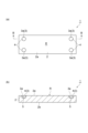
- a sample support 1 comprises a substrate 2 .
- the substrate 2 is made of, for example, an insulating material in the shape of a rectangular plate, and has a first surface 2a and a second surface 2b opposite to the first surface 2a.
- the first surface 2a and the second surface 2b are main surfaces of the substrate 2, and are flat surfaces perpendicular to the thickness direction of the substrate 2, for example.
- the length of one side of the substrate 2 when viewed in the thickness direction of the substrate 2 is, for example, about several centimeters, and the thickness of the substrate 2 is, for example, about 1 ⁇ m to 1000 ⁇ m.
- the substrate 2 has a measurement area R used for sample measurement.
- the measurement area R is the entire area of the substrate 2 .
- the measurement area R is formed with a porous structure that allows the first surface 2a and the second surface 2b to communicate with each other.
- the porous structure has a structure (irregular porous structure) in which voids (pores) extend in irregular directions and are irregularly distributed in three dimensions. Voids in the porous structure form through-holes that open to the first surface 2a and the second surface 2b.
- An irregular porous structure is, for example, a spongy structure.
- the measurement area R is made of sintered glass beads.
- a glass bead sintered body has, for example, a structure in which a large number of glass beads are integrated by sintering.
- the shape of each glass bead is, for example, spherical.
- the shape and size of the glass beads contained in the substrate 2 may be uniform or may be irregular.
- a plurality of glass beads and a plurality of voids formed between the glass beads form the porous structure described above.
- the voids between the glass beads communicate irregularly with each other.
- the average particle size (diameter) of the glass beads is, for example, about 50 ⁇ m.
- the porosity of the porous structure is, for example, 40% to 50%.
- each calibration section 3 is formed by embedding an embedding member 4 in the substrate 2 .
- the embedding member 4 is formed in a circular plate shape from ceramics, for example. That is, the embedded member 4 is made of a material different from the material of the substrate 2 .
- the embedding member 4 is a solid member without holes.
- a concave portion 5 having a shape (cylindrical shape) corresponding to the embedding member 4 is formed in the first surface 2a of the substrate 2, and the embedding member 4 is embedded in the concave portion 5 without any gap.
- the embedding member 4 is adhered and fixed to the bottom and side surfaces of the recess 5 with an adhesive, for example.
- the embedding member 4 is arranged in the recess 5 so that the surface on the side of the first surface 2a is flush with the first surface 2a.
- the calibration section 3 has a surface 3a that is flush with the first surface 2a. Two surfaces being flush means that the two surfaces lie on the same surface.
- the four calibration units 3 are arranged at the four corners of the substrate 2, respectively.
- the entire area of the substrate 2 is the measurement area R used for the measurement of the sample, and each calibration section 3 is arranged within the measurement area R.
- the water absorption of the calibration section 3 is lower than that of the measurement region R (substrate 2). In other words, the liquid is less likely to be absorbed in the calibration section 3 than in the measurement region R.
- the above relationship is satisfied because the measurement region R has a porous structure and the embedding member 4 is formed solid. That is, the water absorbency of the embedding member 4 is lower than the water absorbency of the measurement region R.
- the measurement area R is formed as a penetration area with a penetration that allows the first surface 2a and the second surface 2b to communicate with each other, whereas the calibration part 3 is such a
- the above relationship is satisfied by being formed as a non-penetrating region (non-communicating region) having no penetrating portion.
- the water absorption of the measurement area R means the water absorption in the part of the measurement area R excluding the calibration part 3 .
- the first surface 2a of the substrate 2 and the surface 3a of the calibration section 3 are conductive. Specifically, a conductive layer is formed on the first surface 2a and the surface 3a.
- the conductive layer is, for example, continuously (integrally) formed over the first surface 2a and the surface 3a, and covers the entirety of the first surface 2a other than the openings of the porous structure and the entirety of the surface 3a. ing.
- the conductive layer is made of a metal material such as Pt and formed into a thin film. The conductive layer is formed thin enough to allow the calibrating section 3 to be visually observed through the conductive layer. [How to use the sample support]
- a sample placed on a slide glass is prepared, and the sample support 1 is arranged on the sample so that the second surface 2b of the substrate 2 (measurement region R) contacts the sample.
- the components of the sample move from the second surface 2b side toward the first surface 2a side through a plurality of paths (voids in the porous structure) formed in the substrate 2 by capillary action.
- the component of the sample that has moved to the first surface 2a side stays on the first surface 2a side due to surface tension.
- the ionization method in this example is a laser desorption ionization method using laser light (energy rays).
- the sample ions emitted from the sample support 1 are detected, for example, by an ion detector of a mass spectrometer.
- a ground electrode is provided between the sample support 1 and the ion detection section, and sample ions move toward the ground electrode while being accelerated by a potential difference generated between the conductive layer and the ground electrode.
- sample ions are detected by the ion detection unit, and mass spectrometric measurement of the sample is performed.
- the ion detector detects sample ions in association with the scanning position of the laser beam.
- a mass spectrometer is a device that performs mass spectrometry on a sample using, for example, time-of-flight mass spectrometry (TOF-MS).
- Mass calibration is performed before starting measurement of such samples.
- a sample for mass calibration (calibration sample, standard sample) is dropped onto the surface 3a of the calibration unit 3, and the above-described ionization and mass spectrometry measurements are performed on the calibration sample. Correction of the mass spectrum is performed based on the measurement results for the calibration sample.
- a mass spectrum is a spectrum obtained by mass spectrometry, and is represented, for example, by a graph in which the horizontal axis is the m/z value and the vertical axis is the detected intensity.
- the m/z value is the mass-to-charge ratio of the ion's mass m divided by the number of charges z.
- the mass spectrum of the calibration sample is known, mass calibration of the mass spectrometer can be performed based on the measurement results of the calibration sample.
- the calibration sample has a lower concentration than the sample for measurement.
- the solvent of the calibration sample dries on the surface 3a of the calibration unit 3, and the components of the calibration sample are concentrated and easily precipitated, making it possible to use a dilute calibration sample. ing. [Action and effect]
- a calibration portion 3 having a surface 3a flush with the first surface 2a is formed in the substrate 2, and the water absorption of the calibration portion 3 is lower than that of the measurement region R. .
- the calibration sample is less likely to absorb water, the solvent dries, and the components of the calibration sample are likely to precipitate on the surface 3a.
- the calibration section 3 is configured to have water absorbency different from that of the measurement region R, the position of the calibration section 3 can be easily grasped by visual observation.
- the calibration part 3 since the calibration part 3 has the surface 3a that is flush with the first surface 2a of the substrate 2, mass calibration can be performed with high accuracy.
- a calibration section 3 is formed within the measurement region R.
- the surface 3a of the calibration unit 3 can be reliably made flush with the first surface 2a. Also, the calibrating unit 3 can be brought closer to the location where the actual measurement is performed.
- the calibrating section 3 is formed by embedding an embedding member 4 having water absorption lower than that of the measurement region R in the substrate 2 .
- the calibrating portion 3 can be formed with good reproducibility, and the adjustment of the size of the calibrating portion 3 can be facilitated.
- the degree of freedom in selecting the material for the substrate 2 can be increased, it is possible to control the ionization efficiency of the sample.
- a plurality of calibration units 3 are formed in the substrate 2 . Thereby, a plurality of calibration samples having different densities can be arranged in the plurality of calibration units 3 to carry out mass calibration, and for example, quantitative measurement can be performed. Quantitative measurements are described below with reference to FIG.
- the calibration section 3 is made of ceramics. As a result, the calibrating portion 3 can be formed with good reproducibility, and the adjustment of the size of the calibrating portion 3 can be facilitated.
- the porous structure of the measurement area R is formed of a sintered body of glass beads. Thereby, a porous structure can be suitably configured.
- the first surface 2a and the surface 3a of the calibration section 3 are conductive. Thereby, the sample can be ionized by the laser desorption ionization method as described above.
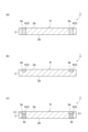
- the sample support 1 may be configured as in the first modified example shown in FIG. 2(a).
- the embedding member 4 is provided so as to penetrate the substrate 2 along the thickness direction.
- mass calibration can be preferably performed similarly to the above-described embodiment.
- the sample support 1 may be configured as in the second modification shown in FIG. 2(b).
- the substrate 2 and the calibration section 3 are made of porous glass.
- Porous glass is a sponge-like glass plate in which a plurality of pores are irregularly formed and connected.
- the calibration section 3 is formed by melting a part of the porous structure in the measurement region R and then solidifying it.
- mass calibration can be preferably performed similarly to the above-described embodiment.
- the formation of the calibration unit 3 can be facilitated and the cost can be reduced.
- the sample support 1 may be configured as in the third modified example shown in FIG. 2(c).
- the substrate 2 is made of porous glass
- the calibration section 3 includes a first portion 31 made of porous glass and a second portion 32 made of the embedded member 4 .
- the first portion 31 is configured similarly to the calibration section 3 of the second modified example.
- the second portion 32 is configured similarly to the calibration section 3 of the embodiment.
- the first portion 31 is arranged to be exposed on the first surface 2 a of the substrate 2
- the second portion 32 is arranged between the first portion 31 and the second surface 2 b of the substrate 2 .
- mass calibration can be preferably performed similarly to the above-described embodiment.
- the calibration section 3 may be formed by filling the porous structure of the measurement region R with a filler.
- the filler is, for example, powdery and filled in the voids of the porous structure.
- mass calibration can be suitably performed in the same manner as in the above-described embodiment.
- the formation of the calibration unit 3 can be facilitated and the cost can be reduced.
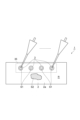
- the sample support 1 may be configured as in the fourth modification shown in FIG.
- a plurality (four in this example) of calibration units 3 are arranged in a row within a rectangular area 35 .
- the plurality of calibration units 3 are arranged at regular intervals along the direction parallel to the long sides of the substrate 2 .
- mass calibration can be preferably performed similarly to the above-described embodiment.
- mass calibration can be performed by arranging a plurality of calibration samples S1 having different densities in a plurality of calibration units 3, respectively, and quantitative measurement can be performed. For example, first, four calibration samples S1 adjusted to have a stepwise change in concentration are dropped into the four calibration units 3 and measured.
- a calibration curve is created by plotting the intensity and concentration of the ions to be measured based on the measurement results for the four calibration samples S1.
- the sample S2 to be measured is measured, and the concentration is estimated based on the calibration curve.
- a density map is created.
- the porous structure of the measurement region R may be made of a fibrous porous body.
- the fibrous porous body has a structure (aggregate) in which a plurality of linear cellulose nanofibers are superimposed.
- the fibrous porous body may have a structure in which, for example, multiple carbon nanofibers, multiple fibrous porous silica, multiple glass fibers, or a combination thereof are stacked.
- the porous structure of the measurement region R may be made of anodized silicon or an anodized valve metal.
- the porous structure has a plurality of through-holes formed to communicate the first surface 2a and the second surface 2b of the substrate 2 with each other. These through-holes are, for example, a plurality of pores extending along the thickness direction of the substrate 2.
- the porous structure is a structure in which a plurality of pores are regularly arranged (regular porous structure). quality structure).
- the porous structure may be, for example, an Al-alumina porous coating.
- anodized valve metal for example, Al (aluminum)
- the porous structure may be, for example, an Al-alumina porous coating.
- a porous structure can be obtained by anodizing the Al substrate and peeling off the oxidized surface portion from the Al substrate.
- the porous structure includes Ta (tantalum), Nb (niobium), Ti (titanium), Hf (hafnium), Zr (zirconium), Zn (zinc), W (tungsten), Bi (bismuth), Sb (antimony ) may be formed by anodizing a valve metal other than Al.
- the porous structure of the measurement region R may be made of porous ceramic or porous metal. Similar to porous glass, porous ceramics have a spongy structure in which a plurality of pores are irregularly formed and connected.
- a porous metal is a spongy metal porous body (also called a metal porous body, foamed metal, porous metal, porous metal, porous metal, etc.) in which a plurality of pores are irregularly formed and connected.
- a conductive layer may not be formed on the first surface 2a of the substrate 2 and the surface 3a of the calibration section 3, and the first surface 2a and the surface 3a may have electrical insulation.
- mass calibration can be suitably performed as in the above embodiment.
- the sample can be ionized by a desorption electrospray ionization method in which the sample is desorbed and ionized by irradiating the sample with charged microdroplets.
- the calibration section 3 may be formed in a portion other than the measurement region R on the substrate 2 .
- the shape of the calibration part 3 is not limited to a circular shape, and may be any shape such as a square shape, a rectangular shape, an elliptical shape, or the like.
- the surface 3 a of the calibration section 3 may be subjected to a hydrophilic treatment so as to have higher hydrophilicity than the first surface 2 a of the substrate 2 .
- a groove may be formed by half-etching at the boundary between the surface 3a and the first surface 2a. In this case, it becomes easy to distinguish and visually recognize the surface 3a from the 1st surface 2a. In addition, it is possible to suppress the infiltration of the calibration sample dropped onto the surface 3a into the first surface 2a.
- the embedding member 4 may be made of a material other than ceramics, such as a metal material or an organic material.
- a plurality of calibration units 3 may not necessarily be formed, and only one calibration unit 3 may be formed.
- the sample is supplied from the second surface 2b side of the substrate 2 in the example of the method of using the sample support 1 described above, the sample may be supplied from the first surface 2a side.
- the sample may be supplied onto the first surface 2a by placing the sample on the first surface 2a to impregnate the substrate 2 with the components of the sample and then removing the sample.
- Reference Signs List 1 sample support, 2: substrate, 2a: first surface, 2b: second surface, 3: calibration part, 3a: surface, R: measurement region.
Landscapes
- Chemical & Material Sciences (AREA)
- Analytical Chemistry (AREA)
- Physics & Mathematics (AREA)
- Engineering & Computer Science (AREA)
- Manufacturing & Machinery (AREA)
- Health & Medical Sciences (AREA)
- Chemical Kinetics & Catalysis (AREA)
- Electrochemistry (AREA)
- Optics & Photonics (AREA)
- Life Sciences & Earth Sciences (AREA)
- Biochemistry (AREA)
- General Health & Medical Sciences (AREA)
- General Physics & Mathematics (AREA)
- Immunology (AREA)
- Pathology (AREA)
- Other Investigation Or Analysis Of Materials By Electrical Means (AREA)
Abstract
Description
[試料支持体の構成]
[試料支持体の使用方法]
[作用及び効果]
[変形例]
Claims (12)
- 試料のイオン化に用いられる試料支持体であって、
第1表面、及び前記第1表面とは反対側の第2表面を有すると共に、前記第1表面及び前記第2表面を互いに連通させる多孔質構造が形成された測定領域を有する基板を備え、
前記基板内には、前記第1表面と面一な表面を有する校正部が形成されており、
前記校正部の吸水性は、前記測定領域の吸水性よりも低い、試料支持体。 - 前記校正部は、前記測定領域内に形成されている、請求項1に記載の試料支持体。
- 前記校正部は、前記基板の材料とは異なる材料により形成されている、請求項1又は2に記載の試料支持体。
- 前記校正部は、前記基板の材料と同一の材料により形成されている、請求項1又は2に記載の試料支持体。
- 前記校正部は、前記測定領域の吸水性よりも低い吸水性を有する部材が前記基板内に埋め込まれることにより形成されている、請求項1~4のいずれか一項に記載の試料支持体。
- 前記多孔質構造は、ガラスを含む材料により形成されており、
前記校正部は、前記多孔質構造の一部を溶融させた後に固化させることにより形成されている、請求項1,2,4のいずれか一項に記載の試料支持体。 - 前記校正部は、前記多孔質構造内に充填材が充填されることにより形成されている、請求項1~4のいずれか一項に記載の試料支持体。
- 前記校正部は、前記基板内に複数形成されている、請求項1~7のいずれか一項に記載の試料支持体。
- 前記校正部は、セラミックスにより形成されている、請求項1~8のいずれか一項に記載の試料支持体。
- 前記多孔質構造は、ガラスビーズの焼結体、多孔質ガラス、繊維多孔質体、陽極酸化されたシリコン、陽極酸化されたバルブ金属、多孔質セラミック、又は多孔質金属により形成されている、請求項1~8のいずれか一項に記載の試料支持体。
- 前記第1表面及び前記校正部の前記表面は、導電性を有する、請求項1~10のいずれか一項に記載の試料支持体。
- 前記第1表面及び前記校正部の前記表面は、電気絶縁性を有する、請求項1~10のいずれか一項に記載の試料支持体。
Priority Applications (3)
| Application Number | Priority Date | Filing Date | Title |
|---|---|---|---|
| CN202280084162.0A CN118451319A (zh) | 2021-12-22 | 2022-09-05 | 试样支撑体 |
| EP22910468.2A EP4382903A4 (en) | 2021-12-22 | 2022-09-05 | SAMPLE SUPPORT |
| US18/709,584 US20250014881A1 (en) | 2021-12-22 | 2022-09-05 | Sample support |
Applications Claiming Priority (2)
| Application Number | Priority Date | Filing Date | Title |
|---|---|---|---|
| JP2021208136A JP7206365B1 (ja) | 2021-12-22 | 2021-12-22 | 試料支持体 |
| JP2021-208136 | 2021-12-22 |
Publications (1)
| Publication Number | Publication Date |
|---|---|
| WO2023119741A1 true WO2023119741A1 (ja) | 2023-06-29 |
Family
ID=84923485
Family Applications (1)
| Application Number | Title | Priority Date | Filing Date |
|---|---|---|---|
| PCT/JP2022/033317 Ceased WO2023119741A1 (ja) | 2021-12-22 | 2022-09-05 | 試料支持体 |
Country Status (5)
| Country | Link |
|---|---|
| US (1) | US20250014881A1 (ja) |
| EP (1) | EP4382903A4 (ja) |
| JP (1) | JP7206365B1 (ja) |
| CN (1) | CN118451319A (ja) |
| WO (1) | WO2023119741A1 (ja) |
Families Citing this family (1)
| Publication number | Priority date | Publication date | Assignee | Title |
|---|---|---|---|---|
| JP7506802B1 (ja) * | 2023-06-07 | 2024-06-26 | 浜松ホトニクス株式会社 | 試料支持体 |
Citations (8)
| Publication number | Priority date | Publication date | Assignee | Title |
|---|---|---|---|---|
| US6627444B1 (en) * | 2000-08-07 | 2003-09-30 | Smiths Detection - Toronto Ltd. | Method and solid phase calibration sample for calibration of analytical instructions |
| WO2007055293A1 (ja) * | 2005-11-14 | 2007-05-18 | Nec Corporation | マイクロチップおよびその使用方法、ならびに質量分析システム |
| JP2008547030A (ja) * | 2005-06-30 | 2008-12-25 | バイオクラテス ライフ サイエンシズ アクチェンゲゼルシャフト | 代謝産物特性分析のための機器及び方法 |
| JP2012083138A (ja) * | 2010-10-07 | 2012-04-26 | Shiseido Co Ltd | 分析方法、粘着テープ及びペン |
| JP2013015516A (ja) * | 2011-06-07 | 2013-01-24 | Shiseido Co Ltd | 分析方法及び分析キット |
| WO2019155741A1 (ja) | 2018-02-09 | 2019-08-15 | 浜松ホトニクス株式会社 | 試料支持体 |
| JP2019194604A (ja) * | 2017-09-21 | 2019-11-07 | 浜松ホトニクス株式会社 | 試料支持体 |
| JP2021124344A (ja) * | 2020-02-04 | 2021-08-30 | 浜松ホトニクス株式会社 | 試料支持体及び試料支持体の製造方法 |
Family Cites Families (1)
| Publication number | Priority date | Publication date | Assignee | Title |
|---|---|---|---|---|
| JP7199054B2 (ja) * | 2018-11-07 | 2023-01-05 | 国立大学法人東海国立大学機構 | サンプル中の元素の質量分析方法、該質量分析方法に用いる分析用デバイス、および、サンプル捕捉用キット |
-
2021
- 2021-12-22 JP JP2021208136A patent/JP7206365B1/ja active Active
-
2022
- 2022-09-05 CN CN202280084162.0A patent/CN118451319A/zh active Pending
- 2022-09-05 EP EP22910468.2A patent/EP4382903A4/en active Pending
- 2022-09-05 US US18/709,584 patent/US20250014881A1/en active Pending
- 2022-09-05 WO PCT/JP2022/033317 patent/WO2023119741A1/ja not_active Ceased
Patent Citations (8)
| Publication number | Priority date | Publication date | Assignee | Title |
|---|---|---|---|---|
| US6627444B1 (en) * | 2000-08-07 | 2003-09-30 | Smiths Detection - Toronto Ltd. | Method and solid phase calibration sample for calibration of analytical instructions |
| JP2008547030A (ja) * | 2005-06-30 | 2008-12-25 | バイオクラテス ライフ サイエンシズ アクチェンゲゼルシャフト | 代謝産物特性分析のための機器及び方法 |
| WO2007055293A1 (ja) * | 2005-11-14 | 2007-05-18 | Nec Corporation | マイクロチップおよびその使用方法、ならびに質量分析システム |
| JP2012083138A (ja) * | 2010-10-07 | 2012-04-26 | Shiseido Co Ltd | 分析方法、粘着テープ及びペン |
| JP2013015516A (ja) * | 2011-06-07 | 2013-01-24 | Shiseido Co Ltd | 分析方法及び分析キット |
| JP2019194604A (ja) * | 2017-09-21 | 2019-11-07 | 浜松ホトニクス株式会社 | 試料支持体 |
| WO2019155741A1 (ja) | 2018-02-09 | 2019-08-15 | 浜松ホトニクス株式会社 | 試料支持体 |
| JP2021124344A (ja) * | 2020-02-04 | 2021-08-30 | 浜松ホトニクス株式会社 | 試料支持体及び試料支持体の製造方法 |
Non-Patent Citations (1)
| Title |
|---|
| See also references of EP4382903A4 |
Also Published As
| Publication number | Publication date |
|---|---|
| US20250014881A1 (en) | 2025-01-09 |
| CN118451319A (zh) | 2024-08-06 |
| EP4382903A4 (en) | 2025-07-23 |
| JP2023092871A (ja) | 2023-07-04 |
| JP7206365B1 (ja) | 2023-01-17 |
| EP4382903A1 (en) | 2024-06-12 |
Similar Documents
| Publication | Publication Date | Title |
|---|---|---|
| JP6093492B1 (ja) | 試料支持体、及び試料支持体の製造方法 | |
| CN110736784B (zh) | 表面辅助激光解吸电离法、质量分析方法和质量分析装置 | |
| JP6539801B1 (ja) | 試料支持体 | |
| CN111699384B (zh) | 试样支承体 | |
| JP7181901B2 (ja) | 試料支持体、イオン化法及び質量分析方法 | |
| JP2017208345A (ja) | マイクロチャネルプレートの製造方法 | |
| CN111094967B (zh) | 试样支撑体 | |
| WO2019058784A1 (ja) | レーザ脱離イオン化法及び質量分析方法 | |
| JP7206365B1 (ja) | 試料支持体 | |
| CN111512150B (zh) | 试样支承体、试样支承体的制造方法和试样的离子化方法 | |
| CN111051874A (zh) | 激光解吸电离法、质量分析方法、试样支撑体及试样支撑体的制造方法 | |
| CN111094963A (zh) | 激光解吸电离法及质量分析方法 | |
| US20230411133A1 (en) | Sample support, ionization method, and mass spectrometry method | |
| WO2019155835A1 (ja) | 試料支持体、イオン化法及び質量分析方法 | |
| JP7278894B2 (ja) | 試料支持体、アダプタ、イオン化法及び質量分析方法 | |
| JP7471174B2 (ja) | 試料支持体 | |
| JP7786973B2 (ja) | 試料支持体、及び試料支持体の製造方法 | |
| JPWO2019058786A1 (ja) | 試料支持体 | |
| JP7589320B1 (ja) | 試料支持体 | |
| JPWO2019155834A1 (ja) | 試料支持体、イオン化法及び質量分析方法 | |
| WO2020202728A1 (ja) | イオン化法及び質量分析方法 |
Legal Events
| Date | Code | Title | Description |
|---|---|---|---|
| 121 | Ep: the epo has been informed by wipo that ep was designated in this application |
Ref document number: 22910468 Country of ref document: EP Kind code of ref document: A1 |
|
| WWE | Wipo information: entry into national phase |
Ref document number: 22910568.2 Country of ref document: EP |
|
| ENP | Entry into the national phase |
Ref document number: 2022910468 Country of ref document: EP Effective date: 20240306 |
|
| WWE | Wipo information: entry into national phase |
Ref document number: 18709584 Country of ref document: US |
|
| WWE | Wipo information: entry into national phase |
Ref document number: 202280084162.0 Country of ref document: CN |
|
| NENP | Non-entry into the national phase |
Ref country code: DE |