WO2023120012A1 - 測定装置 - Google Patents
測定装置 Download PDFInfo
- Publication number
- WO2023120012A1 WO2023120012A1 PCT/JP2022/043362 JP2022043362W WO2023120012A1 WO 2023120012 A1 WO2023120012 A1 WO 2023120012A1 JP 2022043362 W JP2022043362 W JP 2022043362W WO 2023120012 A1 WO2023120012 A1 WO 2023120012A1
- Authority
- WO
- WIPO (PCT)
- Prior art keywords
- exposure
- light
- measuring device
- pulse width
- timing
- Prior art date
- Legal status (The legal status is an assumption and is not a legal conclusion. Google has not performed a legal analysis and makes no representation as to the accuracy of the status listed.)
- Ceased
Links
Images




Classifications
-
- G—PHYSICS
- G01—MEASURING; TESTING
- G01S—RADIO DIRECTION-FINDING; RADIO NAVIGATION; DETERMINING DISTANCE OR VELOCITY BY USE OF RADIO WAVES; LOCATING OR PRESENCE-DETECTING BY USE OF THE REFLECTION OR RERADIATION OF RADIO WAVES; ANALOGOUS ARRANGEMENTS USING OTHER WAVES
- G01S17/00—Systems using the reflection or reradiation of electromagnetic waves other than radio waves, e.g. lidar systems
- G01S17/88—Lidar systems specially adapted for specific applications
- G01S17/89—Lidar systems specially adapted for specific applications for mapping or imaging
- G01S17/894—Three-dimensional [3D] imaging with simultaneous measurement of time-of-flight at a two-dimensional [2D] array of receiver pixels, e.g. time-of-flight cameras or flash lidar
-
- G—PHYSICS
- G01—MEASURING; TESTING
- G01S—RADIO DIRECTION-FINDING; RADIO NAVIGATION; DETERMINING DISTANCE OR VELOCITY BY USE OF RADIO WAVES; LOCATING OR PRESENCE-DETECTING BY USE OF THE REFLECTION OR RERADIATION OF RADIO WAVES; ANALOGOUS ARRANGEMENTS USING OTHER WAVES
- G01S17/00—Systems using the reflection or reradiation of electromagnetic waves other than radio waves, e.g. lidar systems
- G01S17/02—Systems using the reflection of electromagnetic waves other than radio waves
- G01S17/06—Systems determining position data of a target
- G01S17/08—Systems determining position data of a target for measuring distance only
- G01S17/10—Systems determining position data of a target for measuring distance only using transmission of interrupted, pulse-modulated waves
- G01S17/18—Systems determining position data of a target for measuring distance only using transmission of interrupted, pulse-modulated waves wherein range gates are used
-
- G—PHYSICS
- G01—MEASURING; TESTING
- G01S—RADIO DIRECTION-FINDING; RADIO NAVIGATION; DETERMINING DISTANCE OR VELOCITY BY USE OF RADIO WAVES; LOCATING OR PRESENCE-DETECTING BY USE OF THE REFLECTION OR RERADIATION OF RADIO WAVES; ANALOGOUS ARRANGEMENTS USING OTHER WAVES
- G01S7/00—Details of systems according to groups G01S13/00, G01S15/00, G01S17/00
- G01S7/48—Details of systems according to groups G01S13/00, G01S15/00, G01S17/00 of systems according to group G01S17/00
- G01S7/483—Details of pulse systems
- G01S7/486—Receivers
- G01S7/4861—Circuits for detection, sampling, integration or read-out
- G01S7/4863—Detector arrays, e.g. charge-transfer gates
-
- G—PHYSICS
- G01—MEASURING; TESTING
- G01S—RADIO DIRECTION-FINDING; RADIO NAVIGATION; DETERMINING DISTANCE OR VELOCITY BY USE OF RADIO WAVES; LOCATING OR PRESENCE-DETECTING BY USE OF THE REFLECTION OR RERADIATION OF RADIO WAVES; ANALOGOUS ARRANGEMENTS USING OTHER WAVES
- G01S7/00—Details of systems according to groups G01S13/00, G01S15/00, G01S17/00
- G01S7/48—Details of systems according to groups G01S13/00, G01S15/00, G01S17/00 of systems according to group G01S17/00
- G01S7/483—Details of pulse systems
- G01S7/486—Receivers
- G01S7/4865—Time delay measurement, e.g. time-of-flight measurement, time of arrival measurement or determining the exact position of a peak
-
- G—PHYSICS
- G01—MEASURING; TESTING
- G01S—RADIO DIRECTION-FINDING; RADIO NAVIGATION; DETERMINING DISTANCE OR VELOCITY BY USE OF RADIO WAVES; LOCATING OR PRESENCE-DETECTING BY USE OF THE REFLECTION OR RERADIATION OF RADIO WAVES; ANALOGOUS ARRANGEMENTS USING OTHER WAVES
- G01S17/00—Systems using the reflection or reradiation of electromagnetic waves other than radio waves, e.g. lidar systems
- G01S17/02—Systems using the reflection of electromagnetic waves other than radio waves
- G01S17/06—Systems determining position data of a target
- G01S17/08—Systems determining position data of a target for measuring distance only
- G01S17/10—Systems determining position data of a target for measuring distance only using transmission of interrupted, pulse-modulated waves
Definitions
- This disclosure relates to a measuring device.
- Patent Document 1 there is an indirect ToF (Time of Flight) measuring device that measures the distance to an object based on irradiating laser light (pulse light) and exposing the reflected and returned light. disclosed.
- ToF Time of Flight
- An object of the present disclosure is to provide a measuring device that can improve measurement accuracy.
- the main disclosure for achieving the above object is set according to a light emitting unit that emits pulsed light, an imaging sensor that outputs a signal value according to the exposure amount of each pixel, and a region to be measured, a timing control unit that exposes the pixels of the imaging sensor to the reflected light during an exposure period with an exposure width shorter than the pulse width of the pulsed light; and a calculator that calculates the arrival time of the reflected light based on the signal value.
- FIG. 1A is an explanatory view of the configuration of the measuring device 1.
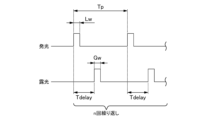
- FIG. 1B is an explanatory diagram of light emission timing and exposure timing.
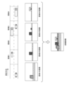
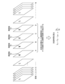
- FIG. 2 is an explanatory diagram of image creation by indirect ToF.
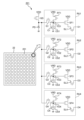
- FIG. 3 is a diagram showing a configuration example of the imaging sensor 22.
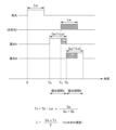
- FIG. 4 is an explanatory diagram of the relationship between light emission and exposure in the measuring device 1 of this embodiment.
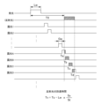
- FIG. 5 is an overall flow chart of the operation of the measuring device 1 of this embodiment.
- FIG. 6 is an explanatory diagram of image acquisition.
- FIG. 7 is a flow chart of distance calculation processing.
- FIG. 8 is a conceptual explanatory diagram of distance calculation processing.
- FIG. 9 is a conceptual explanatory diagram of distance calculation processing.
- FIG. 10 is an explanatory diagram of the relationship between light emission and exposure in a comparative example.
- FIG. 1A is an explanatory view of the configuration of the measuring device 1.
- the measuring device 1 shown in FIG. 1A is a ToF (Time of Flight) type device that measures the distance to an object in front.
- an indirect ToF camera is used. With such a measuring device 1, the effects of fog and rain can be removed, and photography and measurement are possible even in bad weather.
- the measuring device 1 is provided, for example, in a vehicle.
- the measuring device 1 includes a light emitting section 10, an imaging section 20, and a control section 30.
- the light emitting unit 10 irradiates (projects) light onto the space to be photographed.
- the light emitting unit 10 controls light irradiation according to instructions from the control unit 30 .
- the light emitting unit 10 has a light source 12 and a light projecting optical system (not shown) that emits the light generated by the light source 12 .
- the light source 12 has a light emitting element.
- the light source 12 emits pulsed laser light under the control of the controller 30 .
- this pulsed light (pulsed light) is also referred to as light emission pulse.
- the imaging unit 20 (indirect ToF camera) performs imaging based on exposing the light reflected by the object for distance measurement.
- the imaging unit 20 has an imaging sensor 22 and an exposure optical system (not shown) that guides incident (exposed) light to the imaging sensor 22 .
- the imaging sensor 22 captures an image of an object to be captured according to an instruction from the control unit 30 and outputs image data obtained by the capturing to the image acquisition unit 34 of the control unit 30 .
- the value of each pixel (pixel data) that constitutes this image data indicates a signal value corresponding to the amount of exposure. Details of the imaging sensor 22 will be described later.
- the control unit 30 controls the measurement device 1 .
- the control unit 30 is realized by a hardware configuration such as elements and circuits such as a memory and a CPU.
- the control unit 30 implements a predetermined function by having the CPU execute a program stored in the memory.
- FIG. 1A Various functions realized by the control unit 30 are shown in FIG. 1A.
- the control section 30 includes a timing control section 32 , an image acquisition section 34 , a time calculation section 36 and a distance calculation section 38 .
- the timing control section 32 controls the light emission timing of the light emitting section 10 and the exposure timing of the imaging section 20 . Light emission timing and exposure timing will be described later.
- the image acquisition unit 34 acquires image data from the imaging sensor 22 of the imaging unit 20 .
- the image acquisition unit 34 has a memory (not shown) that stores acquired image data.
- the time calculation unit 36 calculates the arrival time (time of flight of light: ToF) from when the light emitting unit 10 emits light until the reflected light reaches the imaging unit 20 .
- the time calculator 36 corresponds to a "calculator".
- the distance calculation unit 38 calculates the distance based on the light arrival time. As will be described later, a distance image can be acquired by calculating the distance for each pixel.
- FIG. 1B is an explanatory diagram of light emission timing and exposure timing.
- FIG. 2 is an explanatory diagram of distance image creation by indirect ToF.
- the control unit 30 causes the light emitting unit 10 to emit light pulses.
- the width of this light emission pulse (hereinafter referred to as pulse width) is Lw.
- control unit 30 exposes the imaging sensor 22 of the imaging unit 20 to reflected light after a time Tdelay has passed since the irradiation of the light emission pulse.
- the exposure period is set by the delay time Tdelay and the exposure width Gw.
- the time Tdelay is the time (delay time) from the irradiation of the light emission pulse to the start of the exposure period.
- the delay time Tdelay is set according to the distance to the area to be measured. That is, by setting a short time from when the light emitting unit 10 irradiates the light emitting pulse to when the imaging sensor 22 starts exposure, it is possible to obtain an image of an object (an object that reflects light) in a short range. Conversely, if the time from when the light emitting unit 10 irradiates the light emitting pulse to when the imaging sensor 22 starts exposure is set longer, an image of an object in a long distance area can be obtained.
- the exposure width Gw is the width of the exposure period (that is, the period from the start of exposure to the end of exposure).
- the width of the exposure period defines the length of the area to be measured in the measurement direction. Therefore, the shorter the exposure width Gw, the higher the distance resolution.
- different exposure periods are set according to the distance to the area to be measured. Although four regions are shown in FIG. 2 for simplification, the number N of regions is actually more than four.
- Light emission and exposure are repeated multiple times at a period Tp shown in FIG. 1B. This is due to charge accumulation in the imaging sensor 22, which will be described later. Also, the farther the area i is, the larger the number of repetitions ni is set. This is because the farther the region i, the weaker the reflected light.
- the object object that reflects light
- the image for each region is sometimes called a "range image”. It should be noted that the value (image data) of each pixel forming an image indicates a signal value corresponding to the amount of exposure.
- the measuring device 1 of the present embodiment acquires image data of a plurality of regions at different distances, and acquires a distance image showing the distance to the object based on the acquired plurality of image data. can.
- This distance image is sometimes called a "frame”.
- the measurable area for one light emission is one, it takes time to acquire image data of many areas, so the measurement time is long (It is difficult to speed up FPS (Flame Per Seconds)). . Therefore, in this embodiment, a plurality of exposure periods are set for one light emission, and a plurality of regions are measured for one light emission. Therefore, in this embodiment, a multi-tap CMOS image sensor is used as the imaging sensor 22 .
- the imaging sensor 22 is not limited to a multi-tap CMOS image sensor. Also, the number of measurable regions for one light emission may be one.
- FIG. 3 is a diagram showing a configuration example of the imaging sensor 22.
- the imaging sensor 22 has a plurality of pixels 221 arranged two-dimensionally (for example, 640 ⁇ 480).
- each pixel 221 one light receiving element PD and a plurality (here, four) of signal readout units RU1 to RU4 corresponding to this one light receiving element PD are provided.
- the signal readout units RU1 to RU4 have the same configuration (only the numerals of the symbols of the constituent elements are different). In the following description, the signal readout unit will be mainly described using the signal readout unit RU1.
- the light-receiving element PD is an element (for example, a photodiode) that generates electric charge according to the amount of exposure.
- the signal readout unit RU1 has a storage unit CS1, a transistor G1, a reset transistor RT1, a source follower transistor SF1, and a selection transistor SL1.
- the storage section CS1 is configured to store charges generated in the light receiving element PD, and has a storage capacitor C1 and a floating diffusion FD1.
- the transistor G1 is provided between the light receiving element PD and the storage section CS1.
- the transistor G1 is turned on during a predetermined exposure period (for example, an exposure period A to be described later) based on an instruction from the timing control section 32 of the control section 30, and supplies charges generated by the light receiving element PD to the storage section CS1.
- the transistors G2 to G4 supply charges generated by the light receiving element PD to the storage units CS2 to CS4 based on instructions from the timing control unit 32, respectively.
- the transistors G1 to G4 correspond to a "drive circuit" that distributes charges generated in the light receiving element PD to the storage units CS1 to CS4 according to the exposure period.
- the image sensor 22 of the present embodiment can store the charges generated in the four exposure periods by dividing them into the storage units (CS1 to CS4) corresponding to each exposure period. Charges are repeatedly accumulated in each accumulation unit in accordance with the number of repetitions n. The charge accumulated in each accumulation unit corresponds to the amount of exposure light received by the light receiving element PD during each exposure period. A signal value is output based on the charge accumulated in the accumulation unit. A signal value based on the charge accumulated in the accumulation unit is a signal value corresponding to the exposure amount of each exposure period.
- four areas can be measured in one shot.
- four range images are obtained in one shot.
- the number (here, four) of range images obtained in one shot is sometimes called a “subframe”.
- a plurality of areas (here, four areas) measured in one shot may be called a "zone”.
- FIG. 10 is an explanatory diagram of the relationship between light emission and exposure in a comparative example.
- the pulse width of the light emission pulse is Lw.
- the pulse width of the reflected light is also Lw.
- exposure A and exposure B are set.
- an exposure period (exposure period A) corresponding to the predetermined area A is set.
- the delay time of the exposure A with respect to the light emission start (time 0) of the light emission pulse is the delay time Ta (corresponding to Tdelay in FIG. 1B).
- the pixel 221 of the imaging sensor 22 acquires the signal value Sa according to the exposure amount of the reflected light in the exposure period A of the exposure width Gw'.
- an exposure period (exposure period B) corresponding to area B is set.
- Region B is the region adjacent to region A in the measurement direction.
- the pixel 221 of the imaging sensor 22 acquires the signal value Sb corresponding to the exposure amount of the reflected light in the exposure period B.
- Tx is the arrival time (time of flight of light: ToF) from the irradiation of light (light emission pulse) to the arrival of reflected light.
- the exposure width Gw' is set to the same value as the pulse width Lw of the light emission pulse. Also, as described above, it is effective to narrow the pulse width in order to increase the distance resolution. However, there are cases where the pulse width Lw cannot be narrowed due to restrictions on the configuration of the light source or on the cost. Therefore, if there is a constraint that the exposure width Gw' is the same as the pulse width Lw, it is difficult to increase the distance resolution.
- FIG. 4 is an explanatory diagram of the relationship between light emission and exposure in the measuring device 1 of this embodiment.
- the pulse width of the light emission pulse (and the pulse width of the reflected light) is Lw, which is the same as in the comparative example.
- exposure A, exposure B, exposure C, and exposure D are set.
- the width of the exposure period (exposure width) of each of the exposures A to D is Gw.
- the H/L levels of the exposures A to D indicate the ON/OFF states of the transistors G1 to G4 in FIG. For example, during the exposure period A (exposure width Gw) of the exposure A, the transistor G1 is turned on, and charges generated in the light receiving element PD are stored in the storage capacitor C1 of the storage section CS1.
- an exposure period (exposure period A) corresponding to the area A is set.
- the delay time of the exposure A with respect to the light emission start (time 0) of the light emission pulse is the delay time Ta (corresponding to Tdelay in FIG. 1B).
- the exposure width Gw is shorter than the exposure width Gw' of the comparative example. That is, the exposure period of the exposure A is set shorter than the pulse width Lw of the light emission pulse. Since the exposure period is short in this way, it is possible to improve the measurement accuracy compared to the comparative example.
- the exposure width Gw of the exposure period A is set to 1/integer of the pulse width Lw of the light emission pulse.
- the exposure width Gw is set to 1/3 of the pulse width Lw of the light emission pulse.
- the exposure width Gw is not limited to one third of the pulse width Lw of the light emission pulse.
- the pixel 221 of the imaging sensor 22 acquires the signal value Sa according to the exposure amount of the reflected light in the exposure period A of the exposure width Gw.
- This signal value Sa corresponds to the value of a pixel (pixel data) forming the image data of the image of area A (range image).
- the explanation is based on the charge in one exposure, but in reality, the signal value S (here, the signal value Sa) is accumulated by repeating the exposure n times. A signal value corresponding to the electric charge (corresponding to the amount of exposure) is obtained.
- Exposure periods B to D corresponding to areas B to D are set for exposures B to D, respectively.
- Region B is a region adjacent to region A in the measurement direction
- region C is a region adjacent to region B in the measurement direction
- region D is a region adjacent to region C in the measurement direction.
- the pixels 221 of the imaging sensor 22 acquire signal values Sb to Sd corresponding to the exposure amount of the reflected light during the exposure periods B to D of the exposures B to D, respectively.
- the signal values Sb to Sd correspond to the pixel values (pixel data) constituting the image data of the images (range images) of the areas B to D, respectively.
- Regions A to D correspond to "three or more continuous exposure periods that can include the pulse width", and correspond to four exposure periods here.
- the control unit 30 calculates the arrival time Tx of the reflected light based on signal values corresponding to three or more consecutive exposure periods that can include the pulse width Lw. . Specifically, the control unit 30 determines the total St of the signal values corresponding to the three or more consecutive exposure periods that can include the pulse width Lw, the total St of any two of the three or more exposure periods The arrival time Tx of the reflected light is calculated based on the ratio (Sx/St) of the signal value Sx corresponding to the exposure amount before the boundary timing.
- the three or more continuous exposure periods that can include the pulse width Lw are the exposure periods A to D (exposure periods A to D).
- the reason why the number is set to 3 or more is to ensure a period in which the reflected light of the pulse width Lw can be exposed in a situation where the exposure period width (exposure width) Gw is set shorter than the pulse width Lw.
- the signal values corresponding to three or more consecutive exposure periods that can include the pulse width Lw are the signal values Sa, Sb, Sc, and Sd.
- the boundary timing is now Tb, Tc, or Td in FIG.
- Tx Tb ⁇ Lw ⁇ Sa/St (3).
- the boundary timing Ts is desirably the boundary between the second and subsequent two exposure periods among the three or more exposure periods that can include the pulse width Lw.
- the boundary timing Ts is preferably Tc or Td.
- control unit 30 calculates the arrival time Tx as the second (formula (4)) or the third (formula (5)) of the above three calculation formulas. Calculated according to the formula. Thereby, the influence of the error of the signal value Sa can be reduced.
- FIG. 5 is an overall flow chart explaining the operation of the measuring device 1 (mainly the control section 30) of this embodiment.
- the control unit 30 executes each process in the figure by the CPU executing a program stored in the memory.
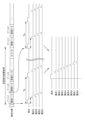
- FIG. 6 is an explanatory diagram of image acquisition.
- FIG. 6 shows the timing of acquiring the images of regions 1 to 8 out of the plurality of regions 1 to N.
- the regions 1 to 4 and the regions 5 to 8 have different delay times of the exposure timing with respect to the light emission timing. Specifically, in regions 5 to 8, the exposure timing (timing corresponding to Tdelay in FIG. 1B) relative to the light emission timing is later than in regions 1 to 4, respectively.
- the lower diagram of FIG. 6 is an explanatory diagram of the exposure timing of the regions 1 to 8 when the light emission pulse is used as a reference. Originally, as shown in the upper diagram of FIG. 6, the areas 1 to 4 emit light and the areas 5 to 8 emit light separately. It shows the exposure timing. As described above, the light emission timings of the regions 4 and 5 are different, but the exposure periods of the regions 4 and 5 are continuous with respect to the light emission pulse.
- the above-mentioned "three or more continuous exposure periods that can include the pulse width Lw" is not limited to exposure periods having the same light emission timing (for example, exposure periods corresponding to regions 1 to 4). , exposure periods with different emission timings (for example, exposure periods corresponding to regions 4 and 5) may be included.
- the timing control unit 32 of the control unit 30 causes the light emitting unit 10 to emit light at the period Tp, and controls the exposure timing of the imaging unit 20 according to the light emission timing.
- the image acquiring section 34 acquires an image captured by the imaging section 20 at each exposure timing (S10).
- images of regions 1-4 are acquired. In other words, each pixel of the image is exposed by the imaging sensor 22 of the imaging unit 20 in the exposure periods A to D delayed from the light emission timing.
- the control unit 30 causes the exposure to be repeated every period Tp, accumulates charges in the accumulation units CS1 to CS4, and acquires the accumulated charges (signal values Sa to Sd).
- the image data of the range images (subframes) of the acquired areas 1 to 4 are written in the image memory of the image acquisition unit 34 (S11).
- the control unit 30 acquires images of areas 5 to 8.
- the delay times (delay times of exposures A to D) with respect to the light emission timing in regions 5-8 are set longer than in regions 1-4.
- the number of repetitions (the number of charge accumulations) is set to increase as the area to be measured becomes farther.
- the image data of the range images (subframes) of areas 5 to 8 are written in the image memory of the image acquisition section 34 .
- control unit 30 determines whether or not the image up to the area N (the image of the entire area) has been acquired (S12). If the image of all regions up to region N has not been acquired (NO in S12), the control unit 30 returns to step S10 and further acquires the image. When the image of the entire area up to the area N has been acquired (YES in S12), the control unit 30 (more specifically, the time calculation unit 36 and the distance calculation unit 38) performs distance calculation processing to acquire a distance image (S13). .
- FIG. 7 is a flow chart of distance calculation processing.
- 8 is a conceptual explanatory diagram of the distance calculation process
- FIG. 9 is a conceptual explanatory diagram of the distance calculation process. Note that FIG. 9 is an explanatory diagram substantially equivalent to FIG.
- control unit 30 identifies the coordinates of pixels to be calculated (S131). That is, the coordinates of the pixel in two dimensions are specified.
- control unit 30 acquires values (signal values) of pixels at specific coordinates from the images of regions 1 to N (S132). In other words, as shown in FIG. 8, the control unit 30 acquires values of pixels at the same coordinates (specific coordinates) from the images of the regions 1 to N.
- the control unit 30 extracts four pixels in continuous areas exposed to the reflected light (S133). For example, the control unit 30 extracts four pixels in a continuous area exposed to the reflected light by extracting four pixels with the highest sum of gradation values. Alternatively, the control unit 30 may, for example, extract four pixels positioned before and after the pixel with the maximum gradation value (a value indicating a large amount of exposure). In FIG. 8, four pixels (pixels at the same coordinates) are extracted from continuous areas A to D exposed to reflected light, and the respective gradation values are Sa, Sb, Sc, and Sd. . The extracted gradation values Sa, Sb, Sc, and Sd correspond to "signal values corresponding to three or more continuous exposure periods that can include the pulse width Lw".
- the time calculation unit 36 of the control unit 30 calculates the arrival time Tx using the four gradation values (Sa, Sb, Sc, Sd) according to Equation (4) or Equation (5) described above (S134). . Further, the distance calculation unit 38 of the control unit 30 uses the arrival time Tx calculated by the time calculation unit 36 and the speed of light Co to obtain the distance L by Equation (2) (S135). If the calculation for all pixels has not been completed (No in S136), the control unit 30 returns to step S131 and performs the same calculation for the next pixel (pixel at another coordinate). When calculations for all pixels have been completed (YES in S136), control unit 30 ends the distance calculation process. Note that the control unit 30 can obtain a distance image (frame: see FIG. 2) by performing distance calculation processing on all pixels.
- the control unit 30 After the distance calculation process (S13), the control unit 30 writes the distance image into the memory (S14). Further, the control unit 30 performs color conversion processing on the distance image (S15).
- the color conversion process is a process of classifying the color of each pixel according to the distance. This makes it easier to understand the existence of the object and the distance to the object.
- the control unit 30 performs display processing (S16). This display processing is processing for displaying a color-coded distance image on a display. Note that the color conversion process (S15) and the display process (S16) may not be performed.
- control unit 30 does not end the process (NO in S17), it returns to step S10 and repeats image acquisition of the regions 1 to N again. If the process is finished (YES in S17), the control section 30 finishes the measurement operation.
- the measuring device 1 of the present embodiment has been described above.
- the measurement apparatus 1 includes a light emitting unit 10 that emits a light emission pulse, an imaging sensor 22 that outputs a signal value corresponding to the exposure amount of each pixel 221, and a pulse width of the light emission pulse that is set according to the area to be measured.
- a timing control unit 32 that exposes the pixels 221 of the imaging sensor 22 to reflected light during an exposure period with an exposure width Gw shorter than Lw, and a signal value (Sa ⁇ Sd) to calculate the arrival time Tx of the reflected light.
- the time calculator 36 calculates the signal value Sx corresponding to the exposure amount before the boundary timing (for example, Tc and Td) of any two exposure periods (for example, the exposure periods C and D) out of the exposure periods A to D.
- the arrival time Tx of the reflected light is calculated based on the ratio of .
- the two exposure periods may be exposure periods B and C, in which case the boundary timings may be Tb and Tc.
- the two exposure periods may be exposure periods B and D, in which case the boundary timings may be Tb and Td.
- the boundary timings are preferably two boundary timings (boundary timings Tc and Td) of exposure periods B to D that are the second and subsequent exposure periods A to D that can include the pulse width Lw. Thereby, the influence of the error of the signal value Sa can be reduced.
- the time calculation unit 36 calculates the arrival time Tx by setting the number of consecutive exposure periods that can include the pulse width Lw to 4, which is 1 more than the integer part 3 of Lw/Gw. This allows setting the minimum number of exposure periods.
- the timing control unit 32 sets the width Gw of the exposure period to 1/integer (1/3 in this embodiment) of the pulse width Lw of the light emission pulse. Thereby, measurement accuracy can be improved.
- the imaging sensor 22 includes, for each pixel 221, a light-receiving element PD that generates a charge corresponding to the exposure amount, four accumulation units CS1 to CS4 that accumulate the charge, and charges corresponding to the exposure periods A to D, respectively.
- a driver circuit (transistors G1 to G4) is provided for allocating and accumulating electric charges in the units CS1 to CS4, and electric charges generated by one light emission pulse are allocated to the respective accumulating units CS1 to CS4 according to the exposure periods A to D for accumulation. Let Thereby, a plurality of exposure periods can be set for one light emission, and a plurality of regions can be measured for one light emission.
Landscapes
- Engineering & Computer Science (AREA)
- Physics & Mathematics (AREA)
- Computer Networks & Wireless Communication (AREA)
- General Physics & Mathematics (AREA)
- Radar, Positioning & Navigation (AREA)
- Remote Sensing (AREA)
- Electromagnetism (AREA)
- Optical Radar Systems And Details Thereof (AREA)
Abstract
Description
<<測定装置の概略>>
図1Aは、測定装置1の構成説明図である。
図1Aに示す測定装置1は、前方の物体との距離を測定するToF(Time of Flight)方式の装置である。本実施形態では、間接ToF方式のカメラが用いられている。このような測定装置1では、霧や雨の影響を除去可能であり、悪天候の場合でも撮影や測定が可能である。測定装置1は、例えば車両に設けられる。
図1Bは、発光タイミングと露光タイミングの説明図である。図2は、間接ToFによる距離画像作成の説明図である。
図3は、撮像センサ22の構成例を示す図である。
図3に示すように、撮像センサ22には複数の画素221が2次元配置(例えば640×480)されている。それぞれの画素221の中に、1つの受光素子PDと、この1つの受光素子PDに対応する複数(ここでは4つ)の信号読み出し部RU1~RU4が設けられている。信号読み出し部RU1~RU4はそれぞれ同じ構成である(構成要素の符号の数字のみ異なる)。以下の説明において、信号読み出し部については、主に信号読み出し部RU1を用いて説明する。
本実施形態の距離の演算について説明する前にまず、比較例について説明する。
図10は、比較例における発光と露光の関係の説明図である。
図10において、発光パルスのパルス幅はLwである。また、反射光のパルス幅もLwとする。比較例では、露光Aと露光Bが設定されている。
Tx=Tb-Lw×Sa/(Sa+Sb)・・・・・(1)で求められる。
L=(Co×Tx)/2・・・・・・・(2)となる。
図4は、本実施形態の測定装置1における発光と露光の関係の説明図である。
図4において、発光パルスのパルス幅(及び反射光のパルス幅)は、比較例と同じLwである。但し、本実施形態では、露光A、露光B、露光C、及び露光Dが設定されている。また、露光A~Dの露光期間の幅(露光幅)は、それぞれGwである。なお、露光A~DのH/Lのレベルは、図3のトランジスタG1~G4のオンオフを示している。例えば、露光Aの露光期間A(露光幅Gw)で、トランジスタG1がオンになり、受光素子PDで発生した電荷が蓄積部CS1の蓄積容量C1に蓄積される。
Tx=Tb-Lw×Sa/St・・・・・・・・・(3)となる。
Tx=Tc-Lw×(Sa+Sb)/St・・・・・・・(4)
Tx=Td-Lw×(Sa+Sb+Sc)/St・・・・・・(5)となる。すなわち、到達時間Txは、算出された信号値の割合(=Sx/St)とパルス幅Lwとの積の値を境界タイミングTsから引いた時間(Tx=Ts-Lw×Sx/St)に相当する。
図5は、本実施形態の測定装置1(主に制御部30)の動作を説明する全体フロー図である。制御部30は、メモリに記憶されたプログラムをCPUが実行することにより、図中の各処理を実行する。図6は、画像取得についての説明図である。図6では、複数の領域1~Nのうちの領域1~8の画像を取得するタイミングが示されている。図6のタイミングを示す図のうち、上図の左側は、ゾーン1(領域1~4)の画像を取得するタイミングを示し、右側は、ゾーン2(領域5~8)の画像を取得するタイミングを示している。
以上、本実施形態の測定装置1について説明した。測定装置1は、発光パルスを発光する発光部10と、画素221ごとの露光量に応じた信号値を出力する撮像センサ22と、測定対象となる領域に応じて設定され、発光パルスのパルス幅Lwよりも短い露光幅Gwの露光期間に撮像センサ22の画素221に反射光を露光させるタイミング制御部32と、パルス幅Lwを包含可能な連続する露光期間A~Dに対応する信号値(Sa~Sd)に基づいて、反射光の到達時間Txを算出する時間算出部36を備えている。これにより、距離分解能を高めることができ、測定精度を高めることができる。
Tx=Ts-Lw×(Sx/St)として算出する。これにより、到達時間Txの測定精度を高めることができる。
Claims (7)
- パルス光を発光する発光部と、
画素ごとの露光量に応じた信号値を出力する撮像センサと、
測定対象となる領域に応じて設定され、前記パルス光のパルス幅よりも短い露光幅の露光期間に前記撮像センサの前記画素に反射光を露光させるタイミング制御部と、
前記パルス幅を包含可能な連続する3以上の前記露光期間に対応する前記信号値に基づいて、前記反射光の到達時間を算出する算出部と、を備える測定装置。 - 請求項1に記載の測定装置であって、
前記算出部は、前記パルス幅を包含可能な3以上の前記露光期間のうちのいずれかの2つの前記露光期間の境界タイミングよりも前の前記露光量に相当する信号値の割合に基づいて、前記反射光の到達時間を算出する測定装置。 - 請求項2に記載の測定装置であって、
前記パルス光の前記パルス幅をLwとし、
前記パルス幅を包含可能な連続する3以上の前記露光期間に対応する前記信号値の合計をStとし、
前記境界タイミングよりも前の前記露光量に相当する前記信号値をSxとし、
前記パルス光の発光から前記境界タイミングまでの時間をTsとしたとき、
前記算出部は、前記到達時間Txを、
Tx=Ts-Lw×(Sx/St)として算出する測定装置。 - 請求項2又は3に記載の測定装置であって、
前記境界タイミングは、前記パルス幅を包含可能な3以上の前記露光期間のうちの2番目以降の前記露光期間の2つの境界のタイミングである測定装置。 - 請求項1~4の何れか一項に記載の測定装置であって、
前記パルス光の前記パルス幅をLwとし、
前記露光期間の幅をGwとしたとき、
前記算出部は、前記パルス幅を包含可能な連続する前記露光期間の数を、Lw/Gwの整数部より1多い数として、前記到達時間を算出する、
測定装置。 - 請求項1~5の何れか一項に記載の測定装置であって、
前記タイミング制御部は、
前記露光期間の幅を、前記パルス光の前記パルス幅の整数分の1に設定する、
測定装置。 - 請求項1~6の何れか一項に記載の測定装置であって、
前記撮像センサは、
前記画素ごとに、露光量に応じた電荷を発生する受光素子と、前記電荷を蓄積する複数の蓄積部と、前記露光期間に応じて前記電荷をそれぞれの前記蓄積部に振り分けて蓄積させる駆動回路とを有し、
1つの前記パルス光によって発生した前記電荷を前記露光期間に応じてそれぞれの前記蓄積部に振り分けて蓄積させる、
測定装置。
Priority Applications (4)
| Application Number | Priority Date | Filing Date | Title |
|---|---|---|---|
| CN202280085641.4A CN118451343A (zh) | 2021-12-24 | 2022-11-24 | 测定装置 |
| EP22910730.5A EP4455731A4 (en) | 2021-12-24 | 2022-11-24 | MEASURING DEVICE |
| JP2023569193A JPWO2023120012A1 (ja) | 2021-12-24 | 2022-11-24 | |
| US18/722,939 US20250052902A1 (en) | 2021-12-24 | 2022-11-24 | Measurement device |
Applications Claiming Priority (2)
| Application Number | Priority Date | Filing Date | Title |
|---|---|---|---|
| JP2021211069 | 2021-12-24 | ||
| JP2021-211069 | 2021-12-24 |
Publications (1)
| Publication Number | Publication Date |
|---|---|
| WO2023120012A1 true WO2023120012A1 (ja) | 2023-06-29 |
Family
ID=86902252
Family Applications (1)
| Application Number | Title | Priority Date | Filing Date |
|---|---|---|---|
| PCT/JP2022/043362 Ceased WO2023120012A1 (ja) | 2021-12-24 | 2022-11-24 | 測定装置 |
Country Status (5)
| Country | Link |
|---|---|
| US (1) | US20250052902A1 (ja) |
| EP (1) | EP4455731A4 (ja) |
| JP (1) | JPWO2023120012A1 (ja) |
| CN (1) | CN118451343A (ja) |
| WO (1) | WO2023120012A1 (ja) |
Citations (5)
| Publication number | Priority date | Publication date | Assignee | Title |
|---|---|---|---|---|
| JP2016095234A (ja) * | 2014-11-14 | 2016-05-26 | 株式会社デンソー | 光飛行型測距装置 |
| JP2017530344A (ja) * | 2014-09-03 | 2017-10-12 | バスラー アーゲーBasler Ag | 深度画像の単純化された検出のための方法およびデバイス |
| US20200158838A1 (en) * | 2018-11-20 | 2020-05-21 | The University Court Of The University Of Edinburgh | Methods and systems for spatially distributed strobing |
| JP2021025833A (ja) | 2019-08-01 | 2021-02-22 | 株式会社ブルックマンテクノロジ | 距離画像撮像装置、及び距離画像撮像方法 |
| WO2021201269A1 (ja) * | 2020-04-02 | 2021-10-07 | 株式会社小糸製作所 | ゲーティングカメラ、車両用センシングシステム、車両用灯具 |
Family Cites Families (2)
| Publication number | Priority date | Publication date | Assignee | Title |
|---|---|---|---|---|
| JP2001337166A (ja) * | 2000-05-26 | 2001-12-07 | Minolta Co Ltd | 3次元入力方法および3次元入力装置 |
| JP5675468B2 (ja) * | 2011-03-31 | 2015-02-25 | 本田技研工業株式会社 | 測距システム |
-
2022
- 2022-11-24 EP EP22910730.5A patent/EP4455731A4/en active Pending
- 2022-11-24 JP JP2023569193A patent/JPWO2023120012A1/ja active Pending
- 2022-11-24 US US18/722,939 patent/US20250052902A1/en active Pending
- 2022-11-24 WO PCT/JP2022/043362 patent/WO2023120012A1/ja not_active Ceased
- 2022-11-24 CN CN202280085641.4A patent/CN118451343A/zh active Pending
Patent Citations (5)
| Publication number | Priority date | Publication date | Assignee | Title |
|---|---|---|---|---|
| JP2017530344A (ja) * | 2014-09-03 | 2017-10-12 | バスラー アーゲーBasler Ag | 深度画像の単純化された検出のための方法およびデバイス |
| JP2016095234A (ja) * | 2014-11-14 | 2016-05-26 | 株式会社デンソー | 光飛行型測距装置 |
| US20200158838A1 (en) * | 2018-11-20 | 2020-05-21 | The University Court Of The University Of Edinburgh | Methods and systems for spatially distributed strobing |
| JP2021025833A (ja) | 2019-08-01 | 2021-02-22 | 株式会社ブルックマンテクノロジ | 距離画像撮像装置、及び距離画像撮像方法 |
| WO2021201269A1 (ja) * | 2020-04-02 | 2021-10-07 | 株式会社小糸製作所 | ゲーティングカメラ、車両用センシングシステム、車両用灯具 |
Non-Patent Citations (1)
| Title |
|---|
| See also references of EP4455731A4 |
Also Published As
| Publication number | Publication date |
|---|---|
| CN118451343A (zh) | 2024-08-06 |
| EP4455731A1 (en) | 2024-10-30 |
| EP4455731A4 (en) | 2025-03-26 |
| JPWO2023120012A1 (ja) | 2023-06-29 |
| US20250052902A1 (en) | 2025-02-13 |
Similar Documents
| Publication | Publication Date | Title |
|---|---|---|
| JP6676866B2 (ja) | 測距撮像装置及び固体撮像素子 | |
| US20190391266A1 (en) | Distance measuring device | |
| JP5295511B2 (ja) | 測距装置及び測距方法 | |
| JPWO2017150246A1 (ja) | 撮像装置、及びそれに用いられる固体撮像素子 | |
| JP6480712B2 (ja) | 撮像装置及びその制御方法 | |
| US20110304696A1 (en) | Time-of-flight imager | |
| JP5675468B2 (ja) | 測距システム | |
| JP2015164284A (ja) | 固体撮像素子、動き情報取得装置、および撮像装置 | |
| JP5675469B2 (ja) | 測距システム | |
| US20230003895A1 (en) | Method and apparatus for controlling distance measurement apparatus | |
| CN114600150B (zh) | 图像处理装置、图像处理方法、图像处理程序以及图像处理系统 | |
| US10282036B2 (en) | Optical touch system and image processing method thereof | |
| JP7828371B2 (ja) | 測定装置 | |
| WO2023139916A1 (ja) | 測定装置 | |
| US20230204727A1 (en) | Distance measurement device and distance measurement method | |
| JP7275941B2 (ja) | 3次元情報取得装置及び3次元情報取得方法 | |
| EP4455731A1 (en) | Measurement device | |
| US11768277B2 (en) | Time-of-flight sensor and control method thereof | |
| WO2023166988A1 (ja) | 測定装置 | |
| JP2014021100A (ja) | 3次元情報検出装置および3次元情報検出方法 | |
| US20230019246A1 (en) | Time-of-flight imaging circuitry, time-of-flight imaging system, and time-of-flight imaging method | |
| EP4492811A1 (en) | Photoelectric conversion circuit, and photoelectric conversion device | |
| US20250088756A1 (en) | Image sensing device, image processing device, and imaging device including the image sensing device and the image processing device | |
| EP4468035A1 (en) | Measurement device | |
| JP6366325B2 (ja) | 撮像システム |
Legal Events
| Date | Code | Title | Description |
|---|---|---|---|
| 121 | Ep: the epo has been informed by wipo that ep was designated in this application |
Ref document number: 22910730 Country of ref document: EP Kind code of ref document: A1 |
|
| ENP | Entry into the national phase |
Ref document number: 2023569193 Country of ref document: JP Kind code of ref document: A |
|
| WWE | Wipo information: entry into national phase |
Ref document number: 18722939 Country of ref document: US |
|
| WWE | Wipo information: entry into national phase |
Ref document number: 202280085641.4 Country of ref document: CN |
|
| NENP | Non-entry into the national phase |
Ref country code: DE |
|
| ENP | Entry into the national phase |
Ref document number: 2022910730 Country of ref document: EP Effective date: 20240724 |