WO2023120030A1 - 電力変換器の制御装置、プログラム - Google Patents
電力変換器の制御装置、プログラム Download PDFInfo
- Publication number
- WO2023120030A1 WO2023120030A1 PCT/JP2022/043527 JP2022043527W WO2023120030A1 WO 2023120030 A1 WO2023120030 A1 WO 2023120030A1 JP 2022043527 W JP2022043527 W JP 2022043527W WO 2023120030 A1 WO2023120030 A1 WO 2023120030A1
- Authority
- WO
- WIPO (PCT)
- Prior art keywords
- coil
- current
- mode
- power converter
- storage unit
- Prior art date
- Legal status (The legal status is an assumption and is not a legal conclusion. Google has not performed a legal analysis and makes no representation as to the accuracy of the status listed.)
- Ceased
Links
Images


Classifications
-
- B—PERFORMING OPERATIONS; TRANSPORTING
- B60—VEHICLES IN GENERAL
- B60L—PROPULSION OF ELECTRICALLY-PROPELLED VEHICLES; SUPPLYING ELECTRIC POWER FOR AUXILIARY EQUIPMENT OF ELECTRICALLY-PROPELLED VEHICLES; ELECTRODYNAMIC BRAKE SYSTEMS FOR VEHICLES IN GENERAL; MAGNETIC SUSPENSION OR LEVITATION FOR VEHICLES; MONITORING OPERATING VARIABLES OF ELECTRICALLY-PROPELLED VEHICLES; ELECTRIC SAFETY DEVICES FOR ELECTRICALLY-PROPELLED VEHICLES
- B60L9/00—Electric propulsion with power supply external to the vehicle
- B60L9/16—Electric propulsion with power supply external to the vehicle using AC induction motors
- B60L9/18—Electric propulsion with power supply external to the vehicle using AC induction motors fed from DC supply lines
-
- B—PERFORMING OPERATIONS; TRANSPORTING
- B60—VEHICLES IN GENERAL
- B60L—PROPULSION OF ELECTRICALLY-PROPELLED VEHICLES; SUPPLYING ELECTRIC POWER FOR AUXILIARY EQUIPMENT OF ELECTRICALLY-PROPELLED VEHICLES; ELECTRODYNAMIC BRAKE SYSTEMS FOR VEHICLES IN GENERAL; MAGNETIC SUSPENSION OR LEVITATION FOR VEHICLES; MONITORING OPERATING VARIABLES OF ELECTRICALLY-PROPELLED VEHICLES; ELECTRIC SAFETY DEVICES FOR ELECTRICALLY-PROPELLED VEHICLES
- B60L15/00—Methods, circuits, or devices for controlling the traction-motor speed of electrically-propelled vehicles
- B60L15/007—Physical arrangements or structures of drive train converters specially adapted for the propulsion motors of electric vehicles
-
- B—PERFORMING OPERATIONS; TRANSPORTING
- B60—VEHICLES IN GENERAL
- B60L—PROPULSION OF ELECTRICALLY-PROPELLED VEHICLES; SUPPLYING ELECTRIC POWER FOR AUXILIARY EQUIPMENT OF ELECTRICALLY-PROPELLED VEHICLES; ELECTRODYNAMIC BRAKE SYSTEMS FOR VEHICLES IN GENERAL; MAGNETIC SUSPENSION OR LEVITATION FOR VEHICLES; MONITORING OPERATING VARIABLES OF ELECTRICALLY-PROPELLED VEHICLES; ELECTRIC SAFETY DEVICES FOR ELECTRICALLY-PROPELLED VEHICLES
- B60L50/00—Electric propulsion with power supplied within the vehicle
- B60L50/10—Electric propulsion with power supplied within the vehicle using propulsion power supplied by engine-driven generators, e.g. generators driven by combustion engines
- B60L50/16—Electric propulsion with power supplied within the vehicle using propulsion power supplied by engine-driven generators, e.g. generators driven by combustion engines with provision for separate direct mechanical propulsion
-
- B—PERFORMING OPERATIONS; TRANSPORTING
- B60—VEHICLES IN GENERAL
- B60L—PROPULSION OF ELECTRICALLY-PROPELLED VEHICLES; SUPPLYING ELECTRIC POWER FOR AUXILIARY EQUIPMENT OF ELECTRICALLY-PROPELLED VEHICLES; ELECTRODYNAMIC BRAKE SYSTEMS FOR VEHICLES IN GENERAL; MAGNETIC SUSPENSION OR LEVITATION FOR VEHICLES; MONITORING OPERATING VARIABLES OF ELECTRICALLY-PROPELLED VEHICLES; ELECTRIC SAFETY DEVICES FOR ELECTRICALLY-PROPELLED VEHICLES
- B60L50/00—Electric propulsion with power supplied within the vehicle
- B60L50/50—Electric propulsion with power supplied within the vehicle using propulsion power supplied by batteries or fuel cells
- B60L50/51—Electric propulsion with power supplied within the vehicle using propulsion power supplied by batteries or fuel cells characterised by AC-motors
-
- B—PERFORMING OPERATIONS; TRANSPORTING
- B60—VEHICLES IN GENERAL
- B60L—PROPULSION OF ELECTRICALLY-PROPELLED VEHICLES; SUPPLYING ELECTRIC POWER FOR AUXILIARY EQUIPMENT OF ELECTRICALLY-PROPELLED VEHICLES; ELECTRODYNAMIC BRAKE SYSTEMS FOR VEHICLES IN GENERAL; MAGNETIC SUSPENSION OR LEVITATION FOR VEHICLES; MONITORING OPERATING VARIABLES OF ELECTRICALLY-PROPELLED VEHICLES; ELECTRIC SAFETY DEVICES FOR ELECTRICALLY-PROPELLED VEHICLES
- B60L50/00—Electric propulsion with power supplied within the vehicle
- B60L50/50—Electric propulsion with power supplied within the vehicle using propulsion power supplied by batteries or fuel cells
- B60L50/60—Electric propulsion with power supplied within the vehicle using propulsion power supplied by batteries or fuel cells using power supplied by batteries
- B60L50/61—Electric propulsion with power supplied within the vehicle using propulsion power supplied by batteries or fuel cells using power supplied by batteries by batteries charged by engine-driven generators, e.g. series hybrid electric vehicles
-
- B—PERFORMING OPERATIONS; TRANSPORTING
- B60—VEHICLES IN GENERAL
- B60L—PROPULSION OF ELECTRICALLY-PROPELLED VEHICLES; SUPPLYING ELECTRIC POWER FOR AUXILIARY EQUIPMENT OF ELECTRICALLY-PROPELLED VEHICLES; ELECTRODYNAMIC BRAKE SYSTEMS FOR VEHICLES IN GENERAL; MAGNETIC SUSPENSION OR LEVITATION FOR VEHICLES; MONITORING OPERATING VARIABLES OF ELECTRICALLY-PROPELLED VEHICLES; ELECTRIC SAFETY DEVICES FOR ELECTRICALLY-PROPELLED VEHICLES
- B60L58/00—Methods or circuit arrangements for monitoring or controlling batteries or fuel cells, specially adapted for electric vehicles
- B60L58/10—Methods or circuit arrangements for monitoring or controlling batteries or fuel cells, specially adapted for electric vehicles for monitoring or controlling batteries
- B60L58/24—Methods or circuit arrangements for monitoring or controlling batteries or fuel cells, specially adapted for electric vehicles for monitoring or controlling batteries for controlling the temperature of batteries
- B60L58/25—Methods or circuit arrangements for monitoring or controlling batteries or fuel cells, specially adapted for electric vehicles for monitoring or controlling batteries for controlling the temperature of batteries by controlling the electric load
-
- H—ELECTRICITY
- H01—ELECTRIC ELEMENTS
- H01M—PROCESSES OR MEANS, e.g. BATTERIES, FOR THE DIRECT CONVERSION OF CHEMICAL ENERGY INTO ELECTRICAL ENERGY
- H01M10/00—Secondary cells; Manufacture thereof
- H01M10/60—Heating or cooling; Temperature control
- H01M10/61—Types of temperature control
- H01M10/615—Heating or keeping warm
-
- H—ELECTRICITY
- H01—ELECTRIC ELEMENTS
- H01M—PROCESSES OR MEANS, e.g. BATTERIES, FOR THE DIRECT CONVERSION OF CHEMICAL ENERGY INTO ELECTRICAL ENERGY
- H01M10/00—Secondary cells; Manufacture thereof
- H01M10/60—Heating or cooling; Temperature control
- H01M10/62—Heating or cooling; Temperature control specially adapted for specific applications
- H01M10/625—Vehicles
-
- H—ELECTRICITY
- H01—ELECTRIC ELEMENTS
- H01M—PROCESSES OR MEANS, e.g. BATTERIES, FOR THE DIRECT CONVERSION OF CHEMICAL ENERGY INTO ELECTRICAL ENERGY
- H01M10/00—Secondary cells; Manufacture thereof
- H01M10/60—Heating or cooling; Temperature control
- H01M10/63—Control systems
- H01M10/637—Control systems characterised by the use of reversible temperature-sensitive devices, e.g. NTC, PTC or bimetal devices; characterised by control of the internal current flowing through the cells, e.g. by switching
-
- H—ELECTRICITY
- H02—GENERATION; CONVERSION OR DISTRIBUTION OF ELECTRIC POWER
- H02M—APPARATUS FOR CONVERSION BETWEEN AC AND AC, BETWEEN AC AND DC, OR BETWEEN DC AND DC, AND FOR USE WITH MAINS OR SIMILAR POWER SUPPLY SYSTEMS; CONVERSION OF DC OR AC INPUT POWER INTO SURGE OUTPUT POWER; CONTROL OR REGULATION THEREOF
- H02M7/00—Conversion of AC power input into DC power output; Conversion of DC power input into AC power output
- H02M7/42—Conversion of DC power input into AC power output without possibility of reversal
- H02M7/44—Conversion of DC power input into AC power output without possibility of reversal by static converters
- H02M7/48—Conversion of DC power input into AC power output without possibility of reversal by static converters using discharge tubes with control electrode or semiconductor devices with control electrode
- H02M7/53—Conversion of DC power input into AC power output without possibility of reversal by static converters using discharge tubes with control electrode or semiconductor devices with control electrode using devices of a triode or transistor type requiring continuous application of a control signal
- H02M7/537—Conversion of DC power input into AC power output without possibility of reversal by static converters using discharge tubes with control electrode or semiconductor devices with control electrode using devices of a triode or transistor type requiring continuous application of a control signal using semiconductor devices only, e.g. single switched pulse inverters
- H02M7/5387—Conversion of DC power input into AC power output without possibility of reversal by static converters using discharge tubes with control electrode or semiconductor devices with control electrode using devices of a triode or transistor type requiring continuous application of a control signal using semiconductor devices only, e.g. single switched pulse inverters in a bridge configuration
- H02M7/53871—Conversion of DC power input into AC power output without possibility of reversal by static converters using discharge tubes with control electrode or semiconductor devices with control electrode using devices of a triode or transistor type requiring continuous application of a control signal using semiconductor devices only, e.g. single switched pulse inverters in a bridge configuration with automatic control of output voltage or current
-
- H—ELECTRICITY
- H02—GENERATION; CONVERSION OR DISTRIBUTION OF ELECTRIC POWER
- H02P—CONTROL OR REGULATION OF ELECTRIC MOTORS, ELECTRIC GENERATORS OR DYNAMO-ELECTRIC CONVERTERS; CONTROLLING TRANSFORMERS, REACTORS OR CHOKE COILS
- H02P21/00—Arrangements or methods for the control of electric machines by vector control, e.g. by control of field orientation
- H02P21/22—Current control, e.g. using a current control loop
-
- H—ELECTRICITY
- H02—GENERATION; CONVERSION OR DISTRIBUTION OF ELECTRIC POWER
- H02P—CONTROL OR REGULATION OF ELECTRIC MOTORS, ELECTRIC GENERATORS OR DYNAMO-ELECTRIC CONVERTERS; CONTROLLING TRANSFORMERS, REACTORS OR CHOKE COILS
- H02P27/00—Arrangements or methods for the control of AC motors characterised by the kind of supply voltage
- H02P27/04—Arrangements or methods for the control of AC motors characterised by the kind of supply voltage using variable-frequency supply voltage, e.g. inverter or converter supply voltage
- H02P27/06—Arrangements or methods for the control of AC motors characterised by the kind of supply voltage using variable-frequency supply voltage, e.g. inverter or converter supply voltage using DC to AC converters or inverters
-
- B—PERFORMING OPERATIONS; TRANSPORTING
- B60—VEHICLES IN GENERAL
- B60L—PROPULSION OF ELECTRICALLY-PROPELLED VEHICLES; SUPPLYING ELECTRIC POWER FOR AUXILIARY EQUIPMENT OF ELECTRICALLY-PROPELLED VEHICLES; ELECTRODYNAMIC BRAKE SYSTEMS FOR VEHICLES IN GENERAL; MAGNETIC SUSPENSION OR LEVITATION FOR VEHICLES; MONITORING OPERATING VARIABLES OF ELECTRICALLY-PROPELLED VEHICLES; ELECTRIC SAFETY DEVICES FOR ELECTRICALLY-PROPELLED VEHICLES
- B60L2210/00—Converter types
- B60L2210/40—DC to AC converters
-
- B—PERFORMING OPERATIONS; TRANSPORTING
- B60—VEHICLES IN GENERAL
- B60L—PROPULSION OF ELECTRICALLY-PROPELLED VEHICLES; SUPPLYING ELECTRIC POWER FOR AUXILIARY EQUIPMENT OF ELECTRICALLY-PROPELLED VEHICLES; ELECTRODYNAMIC BRAKE SYSTEMS FOR VEHICLES IN GENERAL; MAGNETIC SUSPENSION OR LEVITATION FOR VEHICLES; MONITORING OPERATING VARIABLES OF ELECTRICALLY-PROPELLED VEHICLES; ELECTRIC SAFETY DEVICES FOR ELECTRICALLY-PROPELLED VEHICLES
- B60L2240/00—Control parameters of input or output; Target parameters
- B60L2240/40—Drive Train control parameters
- B60L2240/54—Drive Train control parameters related to batteries
- B60L2240/545—Temperature
-
- B—PERFORMING OPERATIONS; TRANSPORTING
- B60—VEHICLES IN GENERAL
- B60L—PROPULSION OF ELECTRICALLY-PROPELLED VEHICLES; SUPPLYING ELECTRIC POWER FOR AUXILIARY EQUIPMENT OF ELECTRICALLY-PROPELLED VEHICLES; ELECTRODYNAMIC BRAKE SYSTEMS FOR VEHICLES IN GENERAL; MAGNETIC SUSPENSION OR LEVITATION FOR VEHICLES; MONITORING OPERATING VARIABLES OF ELECTRICALLY-PROPELLED VEHICLES; ELECTRIC SAFETY DEVICES FOR ELECTRICALLY-PROPELLED VEHICLES
- B60L58/00—Methods or circuit arrangements for monitoring or controlling batteries or fuel cells, specially adapted for electric vehicles
- B60L58/10—Methods or circuit arrangements for monitoring or controlling batteries or fuel cells, specially adapted for electric vehicles for monitoring or controlling batteries
- B60L58/24—Methods or circuit arrangements for monitoring or controlling batteries or fuel cells, specially adapted for electric vehicles for monitoring or controlling batteries for controlling the temperature of batteries
- B60L58/27—Methods or circuit arrangements for monitoring or controlling batteries or fuel cells, specially adapted for electric vehicles for monitoring or controlling batteries for controlling the temperature of batteries by heating
-
- H—ELECTRICITY
- H01—ELECTRIC ELEMENTS
- H01M—PROCESSES OR MEANS, e.g. BATTERIES, FOR THE DIRECT CONVERSION OF CHEMICAL ENERGY INTO ELECTRICAL ENERGY
- H01M2220/00—Batteries for particular applications
- H01M2220/20—Batteries in motive systems, e.g. vehicle, ship, plane
-
- H—ELECTRICITY
- H02—GENERATION; CONVERSION OR DISTRIBUTION OF ELECTRIC POWER
- H02J—ELECTRIC POWER NETWORKS; CIRCUIT ARRANGEMENTS OR SYSTEMS FOR SUPPLYING OR DISTRIBUTING ELECTRIC POWER; SYSTEMS FOR STORING ELECTRIC ENERGY
- H02J2207/00—Details of circuit arrangements for charging or discharging batteries or supplying loads from batteries
- H02J2207/20—Charging or discharging characterised by the power electronics converter
-
- H—ELECTRICITY
- H02—GENERATION; CONVERSION OR DISTRIBUTION OF ELECTRIC POWER
- H02M—APPARATUS FOR CONVERSION BETWEEN AC AND AC, BETWEEN AC AND DC, OR BETWEEN DC AND DC, AND FOR USE WITH MAINS OR SIMILAR POWER SUPPLY SYSTEMS; CONVERSION OF DC OR AC INPUT POWER INTO SURGE OUTPUT POWER; CONTROL OR REGULATION THEREOF
- H02M3/00—Conversion of DC power input into DC power output
- H02M3/02—Conversion of DC power input into DC power output without intermediate conversion into AC
- H02M3/04—Conversion of DC power input into DC power output without intermediate conversion into AC by static converters
- H02M3/10—Conversion of DC power input into DC power output without intermediate conversion into AC by static converters using discharge tubes with control electrode or semiconductor devices with control electrode
- H02M3/145—Conversion of DC power input into DC power output without intermediate conversion into AC by static converters using discharge tubes with control electrode or semiconductor devices with control electrode using devices of a triode or transistor type requiring continuous application of a control signal
- H02M3/155—Conversion of DC power input into DC power output without intermediate conversion into AC by static converters using discharge tubes with control electrode or semiconductor devices with control electrode using devices of a triode or transistor type requiring continuous application of a control signal using semiconductor devices only
- H02M3/156—Conversion of DC power input into DC power output without intermediate conversion into AC by static converters using discharge tubes with control electrode or semiconductor devices with control electrode using devices of a triode or transistor type requiring continuous application of a control signal using semiconductor devices only with automatic control of output voltage or current, e.g. switching regulators
- H02M3/158—Conversion of DC power input into DC power output without intermediate conversion into AC by static converters using discharge tubes with control electrode or semiconductor devices with control electrode using devices of a triode or transistor type requiring continuous application of a control signal using semiconductor devices only with automatic control of output voltage or current, e.g. switching regulators including plural semiconductor devices as final control devices for a single load
- H02M3/1582—Buck-boost converters
Definitions
- the present disclosure relates to a power converter control device.
- Patent Document 1 there has been known an inverter control device that electrically connects a coil and a battery that constitute a rotating electric machine.
- This control device causes alternating current to flow through the battery by causing current to flow between the coil and the battery via the inverter by switching control of the inverter.
- Joule heat is generated in the battery, raising the temperature of the battery.
- a main object of the present disclosure is to provide a control device and a program for a power converter that can increase the temperature rising capability of a power storage unit.
- the present disclosure provides a chargeable/dischargeable power storage unit, a coil; a power converter that electrically connects the coil and the power storage unit;
- a power converter control device applied to a system comprising a determination unit that determines whether or not it is necessary to raise the temperature of the power storage unit; a coil charging mode for gradually increasing the magnitude of the current flowing through the coil when the determination unit determines that the temperature of the power storage unit needs to be increased; and a mode subsequent to the coil charging mode, wherein the coil
- the switching control of the power converter is performed so that the magnitude of the current flowing through the coil is greater than 0 while repeatedly appearing at a specified cycle including a coil discharge mode in which the magnitude of the current flowing through the coil is gradually reduced. and a temperature increase control unit that performs
- switching control of the power converter is performed so that the magnitude of the current flowing through the coil is greater than 0 in one cycle including the coil charge mode and the coil discharge mode. Therefore, the DC component included in the current flowing through the coil can be increased, and the charge/discharge current of the power storage unit can be increased in the coil charge/discharge mode. As a result, the temperature rising capability of the power storage unit can be enhanced.
- the DC component is increased to increase the temperature rising capability of the power storage unit, so the charging/discharging current of the power storage unit can be increased without increasing the amount of change in the current flowing through the coil. As a result, the noise level generated by the coil due to the switching control by the temperature increase control section can be suppressed.
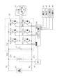
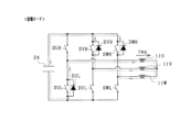
- FIG. 1 is an overall configuration diagram of the control system
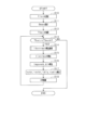
- FIG. 2 is a flowchart showing the procedure of temperature rise control
- FIG. 3 is a diagram showing an equivalent circuit
- FIG. 4 is a diagram showing frequency amplitude response characteristics
- FIG. 5 is a diagram showing an example of a method for setting the noise tolerance
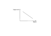
- FIG. 6 is a diagram showing the relationship between battery temperature and maximum chargeable/dischargeable power of the battery
- FIG. 7 is a flowchart showing the procedure for calculating the command battery current effective value Ibatrms*.
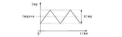
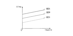
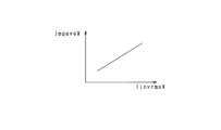
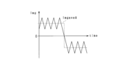
- FIG. 8 is a diagram showing definitions of the coil average current value Imgave and the coil current change amount ⁇ Img
- FIG. 9 is a diagram showing the relationship between the coil average current value Imgave, the coil current change amount ⁇ Img, and the sound pressure level of noise.
- FIG. 10 is a time chart showing changes in the d-axis current, coil current, and inverter current in the coil charge mode, freewheel mode, and coil discharge mode.
- FIG. 11 is a diagram showing an example of a switching pattern in the coil charging mode;
- FIG. 12 is a diagram showing an example of a switching pattern in freewheeling mode;
- FIG. 13 is a diagram showing an example of a switching pattern in the coil discharge mode;
- FIG. 14 is a time chart showing changes in coil current and inverter current in one cycle including coil charge mode, freewheel mode and coil discharge mode
- FIG. 15 is a diagram showing the relationship between the coil average current value, the coil current change amount, and the inverter current effective value
- FIG. 16 is a diagram showing a method of setting the command current average value and the command current change amount
- FIG. 17 is a diagram showing the relationship between the allowable noise value, the command inverter current effective value, and the command current change amount.
- FIG. 18 is a diagram showing the relationship between the commanded inverter current effective value and the commanded average current value
- FIG. 19 is a diagram showing the relationship between the allowable noise value and the command average current value
- FIG. 20 is a time chart showing the transition of the coil current in one cycle including the coil charging mode, the freewheeling mode and the coil discharging mode
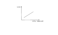
- FIG. 21 is a diagram showing the relationship between the command current average value, the command current change amount, and the charging execution time
- FIG. 22 is a diagram showing the relationship between the charging execution time, the commanded inverter frequency, and the first freewheeling execution time
- FIG. 23 is a diagram showing the relationship between the command current average value and the discharge execution time
- FIG. 24 is a diagram showing the relationship between the command current average value and the discharge execution time
- FIG. 25 is a diagram showing the relationship between the discharge execution time, the commanded inverter frequency, and the second freewheel execution time
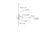
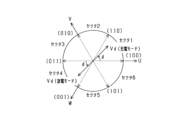
- FIG. 26 is a diagram showing each sector and voltage vector
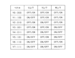
- FIG. 27 is a diagram showing the relationship between voltage vectors and switching patterns
- FIG. 28 is a diagram showing a method of generating a d-axis voltage vector when the current electrical angle belongs to sector 1
- FIG. 29 is a diagram showing the trajectory of the dq-axis current during temperature rise control in the dq-axis current coordinate system
- FIG. 30 is a diagram showing the relationship between vehicle speed and noise tolerance value according to another embodiment
- FIG. 31 is a time chart showing a temperature increase control mode according to another embodiment
- FIG. 32 is a time chart showing a temperature increase control mode according to another embodiment
- FIG. 33 is a time chart showing a temperature increase control mode according to another embodiment
- FIG. 34 is a time chart showing a temperature increase control mode according to another embodiment
- FIG. 35 is a time chart showing a temperature increase control mode according to another embodiment
- FIG. 36 is a diagram showing a power converter according to another embodiment
- FIG. 37 is a diagram showing a power converter according to another embodiment.
- control device of this embodiment is mounted in a vehicle such as an electric vehicle or a hybrid vehicle.
- the system includes a rotating electric machine 10 and an inverter 20 as a "power converter".
- the rotating electric machine 10 is a brushless synchronous machine, and is a permanent magnet synchronous machine in this embodiment.
- the rotary electric machine 10 includes a rotor (not shown) and U-, V-, and W-phase coils 11U, 11V, and 11W, which are stator windings.
- the rotor is in power transmission with the drive wheels of the vehicle.
- the rotary electric machine 10 is a driving power source of the vehicle.
- the inverter 20 includes a series connection of U, V, W phase upper arm switches SUH, SVH, SWH and U, V, W phase lower arm switches SUL, SVL, SWL.
- the first end of the coil of the rotary electric machine 10 is connected to the low potential side terminal of the upper arm switch and the high potential side terminal of the lower arm switch.
- Second ends of the U-, V-, and W-phase coils 11U, 11V, and 11W are connected at a neutral point.
- the U-, V-, and W-phase coils 11U, 11V, and 11W are shifted by an electrical angle of 120°.
- the switches SUH, SUL, SVH, SVL, SWH, and SWL are voltage-controlled semiconductor switching elements, specifically IGBTs.
- the high side terminal of the switch is the collector and the low side terminal is the emitter.
- Freewheel diodes DUH, DUL, DVH, DVL, DWH and DWL are connected in anti-parallel to the respective switches SUH, SUL, SVH, SVL, SWH and SWL.
- the system includes a high potential side path 22H, a low potential side path 22L, a storage battery 30 as a "storage unit", and a smoothing capacitor 24.
- the storage battery 30 is a secondary battery such as a lithium ion storage battery or a nickel metal hydride storage battery.
- the storage battery 30 is, for example, an assembled battery including a series connection body of a plurality of battery cells.
- the positive terminal of the storage battery 30 is connected to the collectors of the upper arm switches SUH, SVH and SWH via the high potential side path 22H.
- the negative terminal of the storage battery 30 is connected to the emitters of the lower arm switches SUL, SVL, SWL via the low potential side path 22L.
- a middle portion of the high potential side path 22H and a middle portion of the low potential side path 22L are connected by a smoothing capacitor 24 .
- the system is equipped with a cut-off switch 60 and an external charger 61.
- the positive terminal of the storage battery 30 is connected to the positive terminal of the external charger 61 via the cutoff switch 60, and the negative terminal of the storage battery 30 is connected to the negative terminal of the external charger 61 via the cutoff switch 60.
- the system includes a battery monitoring device 40.
- the battery monitoring device 40 detects battery information including the terminal voltage of the storage battery 30 , the current flowing through the storage battery 30 , the temperature of the storage battery 30 , and the SOC of the storage battery 30 .
- the system includes a current sensor 41, an angle sensor 42, an inverter temperature sensor 43 and a motor temperature sensor 44.
- the current sensor 41 detects at least two phase currents among the phase currents flowing in the rotary electric machine 10 .
- the angle sensor 42 detects the rotation angle (electrical angle) of the rotor of the rotary electric machine 10 .
- Inverter temperature sensor 43 detects the temperature of inverter 20 (for example, the temperature of upper and lower arm switches).
- the motor temperature sensor 44 detects the temperature of the rotating electric machine 10 (for example, the temperature of the coil). Detected values of the sensors 41 to 44 and the battery monitoring device 40 are input to a control device 50 provided in the system.
- the control device 50 is mainly composed of a microcomputer 50a, and the microcomputer 50a includes a CPU.
- the functions provided by the microcomputer 50a can be provided by software recorded in a physical memory device, a computer that executes the software, only software, only hardware, or a combination thereof.
- the microcomputer 50a is provided by an electronic circuit that is hardware, it can be provided by a digital circuit including many logic circuits, or an analog circuit.
- the microcomputer 50a executes a program stored in a non-transitory tangible storage medium as the storage unit 50b provided therein.
- the program includes, for example, a program for processing shown in FIG. 2 and the like. A method corresponding to the program is executed by executing the program.
- the storage unit 50b is, for example, a nonvolatile memory.
- the program stored in the storage unit 50b can be updated via a network such as the Internet, such as OTA (Over The Air).
- the control device 50 performs switching control of the switches SUH to SWL constituting the inverter 20 based on the input detection value in order to control the control amount (for example, torque) of the rotating electric machine 10 to the command value. As a result, the rotor of the rotary electric machine 10 rotates, allowing the vehicle to run.
- the control device 50 When the vehicle stops and the rotor stops rotating, the control device 50 performs temperature increase control to increase the temperature of the storage battery 30 by switching control of the inverter 20 .
- the temperature increase control of the present embodiment is control that enhances the temperature increase capability of the storage battery 30 while suppressing noise generated by the rotating electric machine 10 accompanying this control.
- the temperature increase control will be described below with reference to FIG.
- the processing shown in FIG. 2 is, for example, repeatedly executed at a predetermined control cycle.
- step S10 the inverter command frequency finv* is set.
- a specified cycle Tinv which is the reciprocal of the inverter command frequency finv*, is a cycle of one cycle consisting of a coil charge mode, a freewheeling mode, a coil discharging mode, and a freewheeling mode, which will be described later.
- a method of setting the inverter command frequency finv* will be described below.
- the inverter current Iinv (corresponding to the "switch side current"), which flows to the storage battery 30.
- the current is assumed to be battery current Ibat, and the current flowing through the smoothing capacitor 24 is assumed to be capacitor current Ic.
- the inverter current Iinv is positive in the direction from the connection point with the smoothing capacitor 24 to the upper arm switch, the battery current Ibat is positive in the discharge side, and the capacitor current Ic is from the high potential side path 22H to the low potential side path 22L. The direction toward is positive.
- a circuit including the storage battery 30, the smoothing capacitor 24, the inverter 20, the high potential side path 22H and the low potential side path 22L is represented as an equivalent circuit shown in FIG.
- inverter 20 is regarded as an alternating current source that outputs alternating current of frequency finv. 3
- Lbat indicates the inductance of the storage battery
- Rbat indicates the internal resistance of the storage battery
- C indicates the capacitance of the smoothing capacitor 24.
- the frequency response characteristic of the battery current Ibat with respect to the inverter current Iinv is expressed by the following equation (eq1), and the frequency response characteristic of the ratio of the amplitude of the battery current Ibat to the amplitude of the inverter current Iinv is expressed in FIG.
- the amplitude ratio has a substantially constant value in a first frequency range from 0 Hz to a predetermined frequency, monotonically increases in a second frequency range following the high frequency side of the first frequency range, and increases in the second frequency range. It monotonically decreases in the third frequency range following the high frequency side.
- inverter command frequency finv* is set to a frequency higher than 1 Hz.
- the inverter command frequency finv* is set to a value in the frequency range fmin to fmax at which the ratio at 1 Hz of the response characteristics shown in FIG. fpk, or the resonance frequency of the response characteristics shown in FIG.
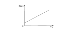
- the noise tolerance value Smax is set.
- the allowable noise value Smax is an allowable value for the noise level generated by the rotary electric machine 10 due to the switching control of the inverter 20 during the temperature increase control.
- the allowable noise value Smax may be made variable based on the inverter command frequency finv* set in step S10.
- map information of the inverter command frequency finv* and the noise tolerance value Smax defined according to the equal loudness curve may be stored in the storage unit 50b.
- the allowable noise value Smax is set based on this map information and the inverter command frequency finv*.
- step S12 the target temperature Tbat* (for example, 25° C.) of the storage battery 30 is acquired.
- the target temperature Tbat* is acquired from the battery monitoring device 40 .
- step S13 the temperature of the storage battery 30 (hereinafter, battery temperature Tbatr) is obtained from the battery monitoring device 40. Then, it is determined whether or not the obtained battery temperature Tbatr is lower than the target temperature Tbat*. When it is determined that the battery temperature Tbatr is lower than the target temperature Tbat*, temperature increase control of the storage battery 30 is executed in steps S14 to S18. Note that the process of step S13 corresponds to the “determination unit”. Further, the processing of steps S14 to S18 corresponds to the "temperature increase control unit".
- FIG. 6 shows the relationship between the temperature of the storage battery 30, the maximum dischargeable power Woutlim of the storage battery 30, and the maximum chargeable power Winlim.
- the maximum dischargeable power Woutlim and the maximum chargeable power Winlim depend on the temperature of the storage battery 30 and tend to decrease as the temperature decreases. Therefore, after the temperature increase control is started, the temperature increase control is continued until it is determined in step S13 that the battery temperature Tbatr has reached the target temperature Tbat*.
- step S14 a command battery current effective value Ibatrms*, which is a command value for the current effective value to be supplied to the storage battery 30, is calculated. This calculation processing will be described below with reference to FIG.
- step S20 the battery temperature rising power Pheat is set.
- the battery temperature rising power Pheat is reduced to the dischargeable power Wb of the storage battery 30 (specifically, for example, the maximum discharge available power Woutlim).
- the cutoff switch 60 is turned on and the external charger 61 and the storage battery 30 are connected and external charging is being performed, the battery temperature rising power Pheat can be combined with the dischargeable power Wb of the storage battery 30 and the external charger 61 can output. It is set to the sum with the power Wc.
- the internal resistance Rbat of the storage battery 30 is estimated based on the battery temperature Tbatr and the SOC obtained from the battery monitoring device 40.
- the internal resistance Rbat may be estimated based on map information that defines the internal resistance Rbat in relation to the battery temperature Tbatr and SOC.
- the map information may be information in which the internal resistance Rbat is defined in association with the battery temperature Tbatr, the SOC, and the inverter command frequency finv*.
- the internal resistance Rbat may be estimated based on this map information, inverter command frequency finv*, battery temperature Tbatr and SOC.
- the command battery current effective value Ibatrms* also depends on the current frequency.
- the command inverter current effective value Iinvrms which is the command value of the effective value of the inverter current Iinv
- Ibatrms* the command battery current effective value Ibatrms*. * is calculated.
- current effective value Iinvrms* is calculated.
- step S16 the command current average value Imgave* and the command current change amount ⁇ I* are calculated.
- the command current average value Imgave* is a command value of the time average value of the current flowing through the coil in one cycle of the temperature increase control.
- the command current change amount ⁇ I* is a command value of the current change amount to be supplied to the coil during the execution period of the coil charging mode, which will be described later, in one cycle of the temperature increase control.
- the command current average value Imgave* and the command current change amount ⁇ I* are obtained by using the effective value of the inverter current Iinv as the command inverter current effective value Iinvrms*, and the noise level generated by the rotating electric machine 10 due to the temperature increase control being the noise allowable value. It is determined so as not to exceed Smax.
- a method of calculating the command current average value Imgave* and the command current change amount ⁇ I* will be described below.
- the coil current Img is the current with the largest absolute value among the currents flowing through the phase coils 11U, 11V, and 11W in the temperature rise control.
- Coil current Img is positive in the direction from inverter 20 to the neutral point.
- the noise generated by the rotating electrical machine 10 due to the temperature increase control is caused by the vibration of the stator of the rotating electrical machine 10 due to the magnetic force change ⁇ generated by the change in the current flowing through the coil.
- the magnetic force change ⁇ is determined by the product of the coil inductance Lmg and the coil current change amount ⁇ Img. Therefore, there is a positive correlation between the sound pressure level of noise and the amount of change in coil current ⁇ Img.
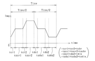
- FIG. 10 shows transitions of the coil current Img, the inverter current Iinv, and the d-axis current Id flowing through the coil in each mode. Note that FIG. 10 shows the transition when the electrical angle is zero.
- the coil charging mode is executed from time t1 to t2 in FIG.
- the coil charging mode is a control mode in which a current flows from the smoothing capacitor 24 and the storage battery 30 to the coil via the inverter 20 (specifically, the upper arm switch of the inverter 20).
- the upper arm switches of some of the phases are turned on, and the lower arm switches of at least one of the remaining phases are turned on.
- the U-phase upper arm switch SUH is turned on, and the V- and W-phase lower arm switches SVL and SWL are turned on.
- the coil charging mode is a control mode that outputs a constant d-axis voltage based on the electrical angle ⁇ detected by the angle sensor 42.
- the absolute value of the coil current Img and the absolute value of the d-axis current Id gradually increase, and the absolute value of the inverter current Iinv and the absolute value of the coil current Img become equal.
- the polarity of the inverter current Iinv is positive.
- the inverter current Iinv and the coil current Img in the coil charging mode are shown shifted slightly for easy viewing.
- the circulation mode is executed from time t2 to t3 in FIG.
- the freewheeling mode is a control mode in which current is circulated in a circuit including a switch in one of the upper and lower arms of the inverter 20 and a coil, as shown in FIG.
- the inverter current Iinv becomes 0 during the execution period of the freewheeling mode.
- all phase switches forming one of the upper and lower arms of the inverter 20 are turned off, and at least one phase switch forming the other arm is turned on.
- the upper arm switches of all phases are turned off and the lower arm switches of all phases are turned on. It should be noted that the switch of the phase through which the current flows through the freewheel diode may be turned off.
- the output voltage of the inverter 20 becomes zero. Also, ignoring the conduction loss, the coil current Img and the d-axis current Id are constant, and the inverter current Iinv is zero.
- the coil discharge mode is executed from time t3 to t4 in FIG.
- the coil discharge mode is a control mode in which current flows from the coil to the smoothing capacitor 24 and the storage battery 30 via the inverter 20, as shown in FIG.
- the upper and lower arm switches of all phases are turned off.
- the coil discharge mode is a control mode in which a d-axis voltage having the same magnitude as the d-axis voltage in the coil charge mode and opposite polarity to the d-axis voltage in the coil charge mode is output based on the electrical angle ⁇ .
- the absolute value of the coil current Img, the absolute value of the d-axis current Id, and the absolute value of the inverter current Iinv gradually decrease. be equal. In this case, the polarity of the inverter current Iinv becomes negative.
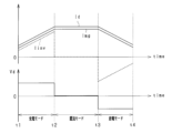
- Tinv shown in FIG. 14 is the above-described specified cycle, which is the reciprocal of the inverter command frequency finv*.
- One cycle of temperature increase control is repeatedly executed for each specified period.
- the specified period Tinv is divided into two equal periods, the first half period and the second half period.
- the control device 50 sequentially executes the coil charging mode and the freewheeling mode (corresponding to the "first freewheeling mode") in the first half cycle (Tinv/2).
- the execution time of the coil charging mode is set to the charging execution time tchr
- the execution time of the freewheeling mode is set to the first freewheeling execution time tzchr.
- the control device 50 sequentially executes the coil discharge mode and the freewheeling mode (corresponding to the "second freewheeling mode") in the second half cycle.
- the execution time of the coil discharge mode is set as the discharge execution time tdis
- the execution time of the freewheeling mode is set as the second freewheeling execution time tzdis.
- the coil current change amount ⁇ Img changes with respect to the coil average current value Imgave.
- the charging execution time tchr and the discharging execution time tdis are expressed as tact.
- the effective value of the inverter current Iinv (hereinafter referred to as the inverter current effective value Iinvrms) is the effective value of the coil current when the current flowing through the coil becomes the coil average current value Imgave for tact during the period of Tinv/2. Since they are equal, they are represented by the following equation (eq3).
- the inverter current effective value Iinvrms is proportional to the product of the coil average current value Imgave and the coil current change amount ⁇ Img.
- contour lines of the inverter current effective value Iinvrms are curves as shown in FIG. 15 .
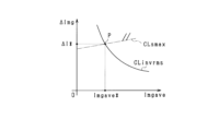
- FIG. 16 shows the contour lines shown in FIG. 15 and the contour lines shown in FIG. 9 in one two-dimensional area.
- the dashed-dotted line CLsmax indicates the contour line in FIG. 9
- the solid line CLinvrms indicates the contour line in FIG.
- the average coil current value Imgave that defines the intersection point P of the contour lines CLsmax and CLinvrms is the average command current value Imgave*
- the coil current change amount ⁇ Img that defines the intersection point P is the command current change amount ⁇ I*.
- the control device 50 calculates the command current average value Imgave* and the command current change amount ⁇ I* based on the allowable noise value Smax and the command inverter current effective value Iinvrms*. Specifically, map information in which the command current average value Imgave* and the command current change amount ⁇ I* are defined in association with the allowable noise value Smax and the command inverter current effective value Iinvrms* is stored in the storage unit 50b. . The control device 50 calculates the command current average value Imgave* and the command current change amount ⁇ I * is calculated.
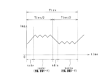
- step S17 the charging execution time tchr, the first circulation execution time tzchr, the discharge execution time tdis, and the second circulation execution time tzdis in one cycle are calculated.
- a method of calculating each time will be described below with reference to FIG.
- ⁇ Ichr be the amount of change in the coil current Img during the charging execution time tchr from time t1 to t2 in FIG. 20, and ⁇ Izchr be the amount of change in the coil current Img during the first return execution time tzchr from time t2 to t3.
- ⁇ Idis be the amount of change in the coil current Img during the discharge execution time tdis from time t3 to t4
- ⁇ Izdis be the amount of change in the coil current Img during the second freewheel execution time tzdis from time t4 to t5.
- equations (eq6) to (eq12) hold.
- Vbat indicates the voltage across the terminals of the storage battery 30
- Rmg indicates the resistance of the coil (specifically, the d-axis resistance)
- Lmg indicates the inductance of the coil (specifically, the d-axis inductance).
- the charging execution time tchr in the prescribed cycle Tinv is longer than the discharging execution time tdis. This is a setting in view of the fact that loss occurs due to current circulation in the freewheeling mode.
- switching control of the inverter 20 is performed in order to repeat the above one cycle.
- the d-axis voltage output by the inverter 20 is realized by adjusting the execution time of each of the two switching patterns according to the electrical angle ⁇ .
- FIG. 26 a vector space consisting of a U-phase voltage vector (100), a V-phase voltage vector (010), and a W-phase voltage vector (001), which are shifted by 120 electrical degrees, is an electrical It is divided into six sectors of every 60° angle.
- FIG. 27 shows switching patterns of the upper and lower arm switches of each phase when voltage vectors (110), (011) and (101) are realized in addition to voltage vectors (100), (010) and (001).
- the d-axis voltage is realized based on the information as to which sector the current electrical angle ⁇ belongs to and two effective voltage vectors that divide the sector and have a phase difference of 60 degrees.
- a case where the current electrical angle ⁇ belongs to sector 1 will be described below as an example.
- the d-axis voltage vector of the inverter 20 belongs to sector 1, and the d-axis voltage vector is located at a position rotated by ⁇ counterclockwise from the voltage vector (100).
- the d-axis voltage vector output in the coil charging mode can be realized by a composite vector of the voltage vector (100)Vt1 and the voltage vector (110)Vt2. Therefore, the d-axis voltage vector can be output by adjusting the ratio between the appearance time of the voltage vector (100) and the appearance time of the voltage vector (110) according to the electrical angle ⁇ .
- “appearance time of (100): appearance time of (110) sin(60°- ⁇ ):sin ⁇ ”.
- "appearance time of (100)+appearance time of (110) tchr”.
- the d-axis voltage vector output in the coil discharge mode has a phase difference of 180 degrees from the d-axis voltage vector output in the coil charge mode. Therefore, the d-axis voltage vector output in the coil discharge mode is a vector at a position rotated counterclockwise by ⁇ from the voltage vector (011) in the sector 4, and the voltage vector (011) and the voltage vector (001) are obtained. can be realized with a composite vector of Therefore, the d-axis voltage vector can be output by adjusting the ratio between the appearance time of the voltage vector (011) and the appearance time of the voltage vector (001) according to the electrical angle ⁇ .
- “appearance time of (011): appearance time of (001) sin (60°- ⁇ ):sin ⁇ ”.
- “appearance time of (011)+appearance time of (001) tdis”.
- switching control of the inverter 20 is performed so that the absolute value of the current flowing through the coil is greater than 0 in one cycle consisting of the coil charging mode, the freewheeling mode, the coil discharging mode, and the freewheeling mode. . Therefore, the DC component contained in the current flowing through the coil can be increased, and the charging/discharging current of the storage battery 30 can be increased in the coil charging/discharging mode. As a result, the temperature rising capability of the storage battery 30 can be enhanced.
- the charge/discharge current of the storage battery 30 can be increased without increasing the amount of change in the current flowing through the coil.
- the noise level generated in the rotary electric machine 10 due to the switching control by the temperature increase control section can be suppressed.
- one cycle of the present embodiment includes the reflux mode. Therefore, even when the change speed of the coil current Img is high, it is possible to prevent the coil current change amount ⁇ Img in the specified period Tinv from greatly exceeding the command current change amount ⁇ I*. As a result, noise can be suppressed accurately in temperature increase control.
- the control device 50 may perform switching control of the inverter 20 so that a stronger field current (Id>0) flows as the d-axis current in the temperature increase control.
- FIG. 29 shows the trajectory of one cycle of the d- and q-axis currents Id and Iq in this case, and the trajectory when a field-weakening current (Id ⁇ 0) flows as the d-axis current. Even if the q-axis current flows due to some factors such as sensor detection error, control error, etc., and torque is generated, the amount of torque fluctuation in the case of strong field current is reduced It can be smaller than the torque fluctuation amount. As a result, it is possible to suppress discomfort given to the user due to the temperature increase control.
- Information on the battery current and the inverter current used in the processing of FIGS. 2 and 7 is not limited to the current effective value, and may be, for example, the current amplitude.
- the control device 50 may set the allowable noise value Smax to be smaller as the traveling speed Vs of the vehicle is lower. This is because the lower the travel speed Vs, the more noticeable the noise generated by the rotating electric machine 10 to the user. Note that this setting may be performed, for example, during coasting, which is coasting of the vehicle.
- the coil charging mode, the freewheeling mode, and the coil discharging mode may be divided into N (N is an integer equal to or greater than 2).
- FIG. 31 shows an example of splitting into two.
- the total value of the divided charging execution times tcr1 and tcr2 should be the charging execution time tchr calculated in step S17.
- the total value of the divided first circulation execution times tzcr1 and tzcr2 should be the first circulation execution time tzchr calculated in step S17.
- the total value of the divided discharge execution times tds1 and tds2 should be the discharge execution time tdis calculated in step S17. Further, in the freewheeling mode following the coil discharge mode, the total value of the divided second freewheeling execution times tzds1 and tzds2 should be the second freewheeling execution time tzdis calculated in step S17.
- a mode in which the coil charging mode and the coil discharging mode are repeated at a cycle shorter than Tinv/2 may be executed as the freewheeling mode. Even in this case, the current flowing through the coil can be maintained.
- one cycle of the temperature increase control may not include the reflux mode, and may consist of the coil charge mode and the coil discharge mode.
- the command current average value Imgave* may change over time.
- 34 and 35 show an example in which one cycle shown in FIG. 33 is repeated.
- the control device 50 repeats one cycle of temperature increase control without setting the current flowing through the coil to 0 until it determines that the battery temperature Tbatr has reached the target temperature Tbat*.
- the control device 50 may provide a period during which the switching control of the inverter 20 is stopped and the current flowing through the coil is temporarily set to 0 between cycles of repeated temperature increase control.
- the chargeable/dischargeable power storage unit is not limited to a storage battery, and may be, for example, a large-capacity capacitor such as an electric double layer capacitor.
- control device 50 determines the command current average value Imgave* and the command The current change amount ⁇ I* and the like may be corrected.
- the prescribed cycle Tinv is not limited to being set to the same period during the temperature increase control, and may be changed during the temperature increase control.
- the prescribed period Tinv may be changed for each cycle.
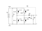
- the power converter is not limited to a multiphase inverter, and may be, for example, a full bridge circuit 70 shown in FIG. 36 or a DCDC converter 80 shown in FIG. These two configurations are described below. 36 and 37, illustration of the configuration of the control device 50 and the like shown in FIG. 1 is omitted.
- a full bridge circuit 70 shown in FIG. 36 includes a series connection of a first upper arm switch SAH and a first lower arm switch SAL, and a series connection of a second upper arm switch SBH and a second lower arm switch SBL.
- the switches SAH, SAL, SBH and SBL which are IGBTs, are illustrated in a simplified manner. Freewheel diodes DAH, DAL, DBH, and DBL are connected in anti-parallel to the switches SAH, SAL, SBH, and SBL.
- Each switch SAH, SAL, SBH, SBL is switching-controlled by a control device (not shown).
- the full bridge circuit 70 has a smoothing capacitor 71 and a coil 72 .
- a coil 72 connects a connection point between the first upper arm switch SAH and the first lower arm switch SAL and a connection point between the second upper arm switch SBH and the second lower arm switch SBL.
- the coil charging mode is a mode in which the first upper arm switch SAH and the second lower arm switch SBL are turned on, and the first lower arm switch SAL and the second upper arm switch SBH are turned off.
- the freewheeling mode following the coil charging mode is a mode in which the first upper arm switch SAH among the switches SAH, SAL, SBH, and SBL is turned on, or the second lower arm switch SBL among the switches SAH, SAL, SBH, and SBL is turned on. This is the mode to turn on.
- the coil discharge mode following the freewheeling mode is a mode in which the switches SAH, SAL, SBH and SBL are turned off.
- the freewheeling mode following the coil discharge mode is the same as the freewheeling mode following the coil charge mode.
- the DCDC converter 80 is a boost chopper circuit, and includes a series connection of a first upper arm switch S1H and a first lower arm switch S1L, and a series connection of a second upper arm switch S2H and a second lower arm switch S2L. ing.
- the switches S1H, S1L, S2H and S2L which are IGBTs, are illustrated in a simplified manner. Freewheel diodes D1H, D1L, D2H and D2L are connected in anti-parallel to the respective switches S1H, S1L, S2H and S2L.
- Each switch S1H, S1L, S2H, S2L is switching-controlled by a control device (not shown).
- the DCDC converter 80 includes a first smoothing capacitor 81 , a second smoothing capacitor 82 , a first coil 83 and a second coil 84 .
- the first coil 83 connects a connection point between the first upper arm switch S1H and the first lower arm switch S1L and one end of the second smoothing capacitor 82 .
- the second coil 84 connects a connection point between the second upper arm switch S2H and the second lower arm switch S2L and one end of the second smoothing capacitor 82 .
- the coil charging mode is a mode in which the first upper arm switch S1H and the second lower arm switch S2L are turned on, and the first lower arm switch S1L and the second upper arm switch S2H are turned off.
- the freewheeling mode following the coil charging mode is a mode in which the first upper arm switch S1H among the switches S1H, S1L, S2H, and S2L is turned on, or the second lower arm switch S2L among the switches S1H, S1L, S2H, and S2L is turned on.
- the coil discharge mode following the freewheeling mode is a mode in which the switches S1H, S1L, S2H and S2L are turned off.
- the freewheeling mode following the coil discharge mode is the same as the freewheeling mode following the coil charge mode.
- the rotating electric machine is not limited to a permanent magnet field type synchronous machine, and may be, for example, a wound field type synchronous machine having a field winding in a rotor.
- the control device 50 may apply the q-axis voltage to the coil in addition to the d-axis voltage during the temperature increase control, and control the field current flowing through the field winding to be zero. Since the field current becomes 0, no torque is generated even if the q-axis current flows through the coil with the application of the q-axis voltage. As a result, it is possible to prevent the rotor from rotating due to the temperature increase control.
- the rotating electric machine is not limited to a synchronous machine.
- the vehicle is equipped with a braking device (for example, a side brake) that applies braking torque to the wheels (driving wheels) of the vehicle.
- the control device 50 may apply the q-axis voltage to the coil in addition to the d-axis voltage on condition that the wheels are prevented from rotating by applying braking torque to the wheels by the braking device.
- the switches of the inverter are not limited to IGBTs, and may be, for example, N-channel MOSFETs with built-in body diodes. In this case, the high potential side terminal becomes the drain and the low potential side terminal becomes the source.
- the rotating electric machine is not limited to star-connected ones, but may be delta-connected ones.
- the mobile object on which the system is installed is not limited to a vehicle, and may be, for example, an aircraft or a ship. Moreover, the system is not limited to being mounted on a moving object, and may be of a stationary type.
- the controller and techniques described in this disclosure can be performed by a dedicated computer provided by configuring a processor and memory programmed to perform one or more functions embodied by a computer program; may be implemented.
- the controller and techniques described in this disclosure may be implemented by a dedicated computer provided by configuring the processor with one or more dedicated hardware logic circuits.
- the control units and techniques described in this disclosure can be implemented by a combination of a processor and memory programmed to perform one or more functions and a processor configured by one or more hardware logic circuits. It may also be implemented by one or more dedicated computers configured.
- the computer program may also be stored as computer-executable instructions on a computer-readable non-transitional tangible recording medium.
- a chargeable/dischargeable power storage unit (30); coils (11U to 11W, 72, 83, 84); a power converter (20, 70, 80) electrically connecting the coil and the power storage unit;
- a power converter control device (50) applied to a system comprising a determination unit that determines whether or not it is necessary to raise the temperature of the power storage unit; a coil charging mode for gradually increasing the magnitude of the current flowing through the coil when the determination unit determines that the temperature of the power storage unit needs to be increased; and a mode subsequent to the coil charging mode, wherein the coil One cycle including a coil discharge mode in which the magnitude of the current passed through the power converter gradually decreases at a specified cycle (Tinv), and the magnitude of the current passed through the coil is greater than zero a temperature rise control unit that performs switching control;
- a power converter control device comprising: [Configuration 2] The temperature rise control unit causes one cycle including the coil charging mode, the
- the system includes: A high-potential-side path (22H) electrically connecting the positive electrode side of the power storage unit and high-potential-side terminals of upper arm switches (SUH to SWH, SAH, SBH, S1H, S2H) constituting the power converter. and, A low potential side path (22L) electrically connecting the negative electrode side of the power storage unit and the low potential side terminals of the lower arm switches (SUL to SWL, SAL, SBL, S1L, S2L) constituting the power converter.
- a high-potential-side path (22H) electrically connecting the positive electrode side of the power storage unit and high-potential-side terminals of upper arm switches (SUH to SWH, SAH, SBH, S1H, S2H) constituting the power converter.
- a low potential side path (22L) electrically connecting the negative electrode side of the power storage unit and the low potential side terminals of the lower arm switches (SUL to SWL, SAL, SBL, S1L, S2L) constituting
- a switch-side current (Iinv) is defined as a current flowing in the upper arm switch side of the high-potential-side path from a connection point with the smoothing capacitor, and the switch-side current flowing in a direction toward the upper arm switch is positive.
- the coil charging mode is a mode in which the magnitude of the switch-side current and the magnitude of the current flowing through the coil are gradually increased while flowing the switch-side current of positive polarity
- the freewheeling mode is a mode in which the magnitude of the current flowing through the coil is maintained while the magnitude of the switch-side current is set to 0,
- the system includes: A high-potential-side path (22H) electrically connecting the positive electrode side of the power storage unit and high-potential-side terminals of upper arm switches (SUH to SWH, SAH, SBH, S1H, S2H) constituting the power converter. and, A low potential side path (22L) electrically connecting the negative electrode side of the power storage unit and the low potential side terminals of the lower arm switches (SUL to SWL, SAL, SBL, S1L, S2L) constituting the power converter.
- a high-potential-side path (22H) electrically connecting the positive electrode side of the power storage unit and high-potential-side terminals of upper arm switches (SUH to SWH, SAH, SBH, S1H, S2H) constituting the power converter.
- a low potential side path (22L) electrically connecting the negative electrode side of the power storage unit and the low potential side terminals of the lower arm switches (SUL to SWL, SAL, SBL, S1L, S2L) constituting
- the specified period is defined by the frequency characteristics of a circuit including the power storage unit, the smoothing capacitor, the power converter, the high potential side path, and the low potential side path, and the connection of the high potential side path to the smoothing capacitor.
- Any one of configurations 1 to 3, wherein the ratio of the current (Ibat) flowing in the power storage unit to the current (Iinv) flowing in the upper arm switch side of the point is set to a period corresponding to a frequency range exceeding 1. 3.
- the power converter control device according to 1.
- the system includes: A high-potential-side path (22H) electrically connecting the positive electrode side of the power storage unit and high-potential-side terminals of upper arm switches (SUH to SWH, SAH, SBH, S1H, S2H) constituting the power converter. and, A low potential side path (22L) electrically connecting the negative electrode side of the power storage unit and the low potential side terminals of the lower arm switches (SUL to SWL, SAL, SBL, S1L, S2L) constituting the power converter.
- a high-potential-side path (22H) electrically connecting the positive electrode side of the power storage unit and high-potential-side terminals of upper arm switches (SUH to SWH, SAH, SBH, S1H, S2H) constituting the power converter.
- a low potential side path (22L) electrically connecting the negative electrode side of the power storage unit and the low potential side terminals of the lower arm switches (SUL to SWL, SAL, SBL, S1L, S2L) constituting
- the frequency characteristic of the high potential side path is higher than the connection point with the smoothing capacitor.
- the ratio of the current (Ibat) flowing through the power storage unit to the current (Iinv) flowing through the arm switch becomes a substantially constant value in the first frequency range from 0 Hz to a predetermined frequency, and increases toward the high frequency side of the first frequency range.
- the power converter control device according to any one of configurations 1 to 3, wherein the prescribed period is set to a period corresponding to a frequency range in which the ratio is greater than the ratio at 1 Hz of the frequency characteristic.
- the coils (11U to 11W) are coils constituting a rotating electric machine (10),
- the power converter control device according to any one of configurations 1 to 5, wherein the temperature increase control unit performs the switching control so that the rotating electric machine does not generate torque due to the current flowing through the coil.
- a command current average value (Imgave*) that is a command value of the time average value of the current flowing through the coil when the coil charging mode and the coil discharging mode are repeated, and the amount of change in the current flowing through the coil in the coil charging mode
- a storage unit (50b) that stores information in which the command current change amount ( ⁇ I*), which is the command value of the current information, and the noise tolerance value are associated
- the temperature rise control unit calculates the command current average value and the command current change amount based on the current information acquired by the acquisition unit and the storage information of the storage unit, and calculates the command current average
- the power converter control device according to configuration 9, wherein the switching control is performed based on the value and the command current change amount.
- a chargeable/dischargeable power storage unit (30); coils (11U to 11W, 72, 83, 84); a power converter (20, 70, 80) electrically connecting the coil and the power storage unit; a computer (50a); In a program applied to a system with to the computer; a process of determining whether or not it is necessary to raise the temperature of the power storage unit; When it is determined that the temperature of the power storage unit needs to be raised, a coil charging mode for gradually increasing the magnitude of the current flowing through the coil, and a mode after the coil charging mode in which the current flowing through the coil is reduced. A process of performing switching control of the power converter so that the magnitude of the current flowing through the coil is greater than 0 while repeating one cycle including a coil discharge mode that gradually decreases in magnitude at a specified cycle; program to run.
Landscapes
- Engineering & Computer Science (AREA)
- Power Engineering (AREA)
- Transportation (AREA)
- Mechanical Engineering (AREA)
- Chemical Kinetics & Catalysis (AREA)
- General Chemical & Material Sciences (AREA)
- Electrochemistry (AREA)
- Manufacturing & Machinery (AREA)
- Chemical & Material Sciences (AREA)
- Sustainable Energy (AREA)
- Sustainable Development (AREA)
- Life Sciences & Earth Sciences (AREA)
- Automation & Control Theory (AREA)
- Inverter Devices (AREA)
- Electric Propulsion And Braking For Vehicles (AREA)
- Charge And Discharge Circuits For Batteries Or The Like (AREA)
- Dc-Dc Converters (AREA)
Abstract
充放電可能な蓄電部(30)と、コイル(11U~11W,72,83,84)と、コイルと蓄電部とを電気的に接続する電力変換器(20,70,80)と、を備えるシステムに適用される電力変換器の制御装置(50)は、蓄電部の昇温が必要であるか否かを判定する判定部と、判定部により蓄電部の昇温が必要であると判定された場合、コイルに流す電流の大きさを漸増させるコイル充電モードと、コイル充電モードの後のモードであって、コイルに流す電流の大きさを漸減させるコイル放電モードとを含む1サイクルを規定周期で繰り返し出現させつつ、コイルに流す電流の大きさが0よりも大きくなるように電力変換器のスイッチング制御を行う昇温制御部と、を備える。
Description
本出願は、2021年12月24日に出願された日本出願番号2021-210972号に基づくもので、ここにその記載内容を援用する。
本開示は、電力変換器の制御装置に関する。
従来、特許文献1に記載されているように、回転電機を構成するコイルとバッテリとを電気的に接続するインバータの制御装置が知られている。この制御装置は、インバータのスイッチング制御によってインバータを介してコイルとバッテリとの間に電流を行き来させることにより、バッテリに交流電流を流す。これにより、バッテリでジュール熱が発生し、バッテリを昇温させる。
特許文献1に記載の制御方法では、コイルに流れる電流の絶対値が周期的に0となり、バッテリの昇温能力が不十分となり得る。このように、バッテリ等の蓄電部の昇温能力を高めることについては、未だ改善の余地を残すものとなっている。
本開示は、蓄電部の昇温能力を高めることができる電力変換器の制御装置及びプログラムを提供することを主たる目的とする。
本開示は、充放電可能な蓄電部と、
コイルと、
前記コイルと前記蓄電部とを電気的に接続する電力変換器と、
を備えるシステムに適用される電力変換器の制御装置において、
前記蓄電部の昇温が必要であるか否かを判定する判定部と、
前記判定部により前記蓄電部の昇温が必要であると判定された場合、前記コイルに流す電流の大きさを漸増させるコイル充電モードと、該コイル充電モードの後のモードであって、前記コイルに流す電流の大きさを漸減させるコイル放電モードとを含む1サイクルを規定周期で繰り返し出現させつつ、前記コイルに流す電流の大きさが0よりも大きくなるように前記電力変換器のスイッチング制御を行う昇温制御部と、を備える。
コイルと、
前記コイルと前記蓄電部とを電気的に接続する電力変換器と、
を備えるシステムに適用される電力変換器の制御装置において、
前記蓄電部の昇温が必要であるか否かを判定する判定部と、
前記判定部により前記蓄電部の昇温が必要であると判定された場合、前記コイルに流す電流の大きさを漸増させるコイル充電モードと、該コイル充電モードの後のモードであって、前記コイルに流す電流の大きさを漸減させるコイル放電モードとを含む1サイクルを規定周期で繰り返し出現させつつ、前記コイルに流す電流の大きさが0よりも大きくなるように前記電力変換器のスイッチング制御を行う昇温制御部と、を備える。
本開示では、コイル充電モード及びコイル放電モードを含む1サイクルにおいてコイルに流す電流の大きさが0よりも大きくなるように電力変換器のスイッチング制御が行われる。このため、コイルに流れる電流に含まれる直流成分を大きくすることができ、コイル充放電モードにおいて蓄電部の充放電電流を増加させることができる。その結果、蓄電部の昇温能力を高めることができる。
また、本開示では、上記直流成分を大きくして蓄電部の昇温能力を高めているため、コイルに流れる電流変化量を大きくすることなく、蓄電部の充放電電流を増加させることができる。これにより、昇温制御部によるスイッチング制御に伴いコイル発生する騒音レベルを抑制することができる。
本開示についての上記目的およびその他の目的、特徴や利点は、添付の図面を参照しながら下記の詳細な記述により、より明確になる。その図面は、
図1は、制御システムの全体構成図であり、
図2は、昇温制御の手順を示すフローチャートであり、
図3は、等価回路を示す図であり、
図4は、周波数振幅応答特性を示す図であり、
図5は、騒音許容値の設定方法の一例を示す図であり、
図6は、電池温度及び電池の最大充放電可能電力の関係を示す図であり、
図7は、指令電池電流実効値Ibatrms*の算出処理の手順を示すフローチャートであり、
図8は、コイル平均電流値Imgave及びコイル電流変化量ΔImgの定義を示す図であり、
図9は、コイル平均電流値Imgave、コイル電流変化量ΔImg及び騒音の音圧レベルの関係を示す図であり、
図10は、コイル充電モード、還流モード及びコイル放電モードにおけるd軸電流、コイル電流及びインバータ電流の推移を示すタイムチャートであり、
図11は、コイル充電モードにおけるスイッチングパターンの一例を示す図であり、
図12は、還流モードにおけるスイッチングパターンの一例を示す図であり、
図13は、コイル放電モードにおけるスイッチングパターンの一例を示す図であり、
図14は、コイル充電モード、還流モード及びコイル放電モードを含む1サイクルにおけるコイル電流及びインバータ電流の推移を示すタイムチャートであり、
図15は、コイル平均電流値、コイル電流変化量及びインバータ電流実効値の関係を示す図であり、
図16は、指令電流平均値及び指令電流変化量の設定方法を示す図であり、
図17は、騒音許容値及び指令インバータ電流実効値と指令電流変化量との関係を示す図であり、
図18は、指令インバータ電流実効値と指令平均電流値との関係を示す図であり、
図19は、騒音許容値と指令平均電流値との関係を示す図であり、
図20は、コイル充電モード、還流モード及びコイル放電モードを含む1サイクルにおけるコイル電流の推移を示すタイムチャートであり、
図21は、指令電流平均値及び指令電流変化量と充電実行時間との関係を示す図であり、
図22は、充電実行時間及び指令インバータ周波数と第1還流実行時間との関係を示す図であり、
図23は、指令電流平均値と放電実行時間との関係を示す図であり、
図24は、指令電流平均値と放電実行時間との関係を示す図であり、
図25は、放電実行時間及び指令インバータ周波数と第2還流実行時間との関係を示す図であり、
図26は、各セクタ及び電圧ベクトルを示す図であり、
図27は、電圧ベクトルとスイッチングパターンとの関係を示す図であり、
図28は、現在の電気角がセクタ1に属する場合のd軸電圧ベクトルの生成方法を示す図であり、
図29は、dq軸電流座標系における昇温制御中のdq軸電流の軌跡を示す図であり、
図30は、その他の実施形態に係る車速と騒音許容値との関係を示す図であり、
図31は、その他の実施形態に係る昇温制御態様を示すタイムチャートであり、
図32は、その他の実施形態に係る昇温制御態様を示すタイムチャートであり、
図33は、その他の実施形態に係る昇温制御態様を示すタイムチャートであり、
図34は、その他の実施形態に係る昇温制御態様を示すタイムチャートであり、
図35は、その他の実施形態に係る昇温制御態様を示すタイムチャートであり、
図36は、その他の実施形態に係る電力変換器を示す図であり、
図37は、その他の実施形態に係る電力変換器を示す図である。
以下、本開示に係る制御装置を具体化した一実施形態について、図面を参照しつつ説明する。本実施形態の制御装置は、電気自動車やハイブリッド車等の車両に搭載されている。
図1に示すように、システムは、回転電機10、及び「電力変換器」としてのインバータ20を備えている。回転電機10は、ブラシレスの同期機であり、本実施形態では永久磁石同期機である。回転電機10は、図示しないロータと、ステータ巻線であるU,V,W相コイル11U,11V,11Wとを備えている。ロータは、車両の駆動輪と動力伝達可能になっている。つまり、回転電機10は、車両の走行動力源である。
インバータ20は、U,V,W相上アームスイッチSUH,SVH,SWHと、U,V,W相下アームスイッチSUL,SVL,SWLとの直列接続体を備えている。各相において、上アームスイッチの低電位側端子及び下アームスイッチの高電位側端子には、回転電機10のコイルの第1端が接続されている。U,V,W相コイル11U,11V,11Wの第2端は、中性点で接続されている。本実施形態において、U,V,W相コイル11U,11V,11Wは、電気角で120°ずつずれている。
本実施形態において、各スイッチSUH,SUL,SVH,SVL,SWH,SWLは、電圧制御形の半導体スイッチング素子であり、具体的にはIGBTである。このため、スイッチの高電位側端子はコレクタであり、低電位側端子はエミッタである。各スイッチSUH,SUL,SVH,SVL,SWH,SWLには、フリーホイールダイオードDUH,DUL,DVH,DVL,DWH,DWLが逆並列接続されている。
システムは、高電位側経路22H、低電位側経路22L、「蓄電部」としての蓄電池30、及び平滑コンデンサ24を備えている。蓄電池30は、リチウムイオン蓄電池又はニッケル水素蓄電池等の二次電池である。蓄電池30は、例えば、複数の電池セルの直列接続体を備える組電池である。蓄電池30の正極端子には、高電位側経路22Hを介して各上アームスイッチSUH,SVH,SWHのコレクタに接続されている。蓄電池30の負極端子には、低電位側経路22Lを介して各下アームスイッチSUL,SVL,SWLのエミッタに接続されている。高電位側経路22Hの中間部と低電位側経路22Lの中間部とは、平滑コンデンサ24により接続されている。
システムは、遮断スイッチ60及び外部充電器61を備えている。外部充電器61の正極側には、遮断スイッチ60を介して蓄電池30の正極端子が接続され、外部充電器61の負極側には、遮断スイッチ60を介して蓄電池30の負極端子が接続されている。
システムは、電池監視装置40を備えている。電池監視装置40は、蓄電池30の端子間電圧、蓄電池30に流れる電流、蓄電池30の温度及び蓄電池30のSOCを含む電池情報を検出する。
システムは、電流センサ41、角度センサ42、インバータ温度センサ43及びモータ温度センサ44を備えている。電流センサ41は、回転電機10に流れる各相電流のうち、少なくとも2相分の電流を検出する。角度センサ42は、回転電機10のロータの回転角(電気角)を検出する。インバータ温度センサ43は、インバータ20の温度(例えば、上,下アームスイッチの温度)を検出する。モータ温度センサ44は、回転電機10の温度(例えば、コイルの温度)を検出する。各センサ41~44及び電池監視装置40の検出値は、システムが備える制御装置50に入力される。
制御装置50は、マイコン50aを主体として構成され、マイコン50aは、CPUを備えている。マイコン50aが提供する機能は、実体的なメモリ装置に記録されたソフトウェアおよびそれを実行するコンピュータ、ソフトウェアのみ、ハードウェアのみ、あるいはそれらの組合せによって提供することができる。例えば、マイコン50aがハードウェアである電子回路によって提供される場合、それは多数の論理回路を含むデジタル回路、又はアナログ回路によって提供することができる。例えば、マイコン50aは、自身が備える記憶部50bとしての非遷移的実体的記録媒体(non-transitory tangible storage medium)に格納されたプログラムを実行する。プログラムには、例えば、図2等に示す処理のプログラムが含まれる。プログラムが実行されることにより、プログラムに対応する方法が実行される。記憶部50bは、例えば不揮発性メモリである。なお、記憶部50bに記憶されるプログラムは、OTA(Over The Air)等、インターネット等のネットワークを介して更新可能である。
制御装置50は、回転電機10の制御量(例えばトルク)を指令値に制御すべく、入力された検出値に基づいて、インバータ20を構成する各スイッチSUH~SWLのスイッチング制御を行う。これにより、回転電機10のロータが回転し、車両を走行させることができる。
制御装置50は、車両が停車してロータの回転が停止している場合、インバータ20のスイッチング制御により蓄電池30を昇温させる昇温制御を行う。本実施形態の昇温制御は、この制御に伴い回転電機10が発生する騒音を抑制しつつ、蓄電池30の昇温能力を高めた制御である。以下、図2を用いて、昇温制御について説明する。図2に示す処理は、例えば、所定の制御周期で繰り返し実行される。
ステップS10では、インバータ指令周波数finv*を設定する。インバータ指令周波数finv*の逆数である規定周期Tinvは、後述するコイル充電モード、還流モード、コイル放電モード及び還流モードからなる1サイクルの周期である。以下、インバータ指令周波数finv*の設定方法について説明する。
図1に示すように、高電位側経路22Hのうち、平滑コンデンサ24との接続点よりも上アームスイッチ側に流れる電流をインバータ電流Iinv(「スイッチ側電流」に相当)とし、蓄電池30に流れる電流を電池電流Ibatとし、平滑コンデンサ24に流れる電流をコンデンサ電流Icとする。インバータ電流Iinvは、平滑コンデンサ24との接続点から上アームスイッチへと向かう方向を正とし、電池電流Ibatは放電側を正とし、コンデンサ電流Icは高電位側経路22Hから低電位側経路22Lへと向かう方向を正とする。蓄電池30、平滑コンデンサ24、インバータ20、高電位側経路22H及び低電位側経路22Lを含む回路は、図3に示す等価回路として表される。等価回路において、インバータ20は、周波数finvの交流電流を出力する交流電流源とみなされる。図3において、Lbatは蓄電池30のインダクタンスを示し、Rbatは蓄電池30の内部抵抗を示し、Cは平滑コンデンサ24の静電容量を示す。
この場合において、インバータ電流Iinvに対する電池電流Ibatの周波数応答特性は下式(eq1)で表され、インバータ電流Iinvの振幅に対する電池電流Ibatの振幅の比率の周波数応答特性は図4で表される。なお、下式(eq1)において、「ω=2π×finv」であり、jは虚数である。この特性において、振幅の比率は、0Hzから所定周波数までの第1周波数範囲において略一定の値となり、第1周波数範囲の高周波数側に続く第2周波数範囲において単調増加し、第2周波数範囲の高周波数側に続く第3周波数範囲において単調減少する。
図2の説明に戻り、ステップS11では、騒音許容値Smaxを設定する。騒音許容値Smaxは、昇温制御時におけるインバータ20のスイッチング制御に伴い回転電機10が発生する騒音レベルの許容値である。
なお、騒音許容値Smaxを、ステップS10で設定したインバータ指令周波数finv*に基づいて可変としてもよい。この場合、例えば、図5に示すように、等ラウドネス曲線に従って規定されたインバータ指令周波数finv*及び騒音許容値Smaxのマップ情報が記憶部50bに記憶されていてもよい。このマップ情報と、インバータ指令周波数finv*とに基づいて、騒音許容値Smaxを設定する。
図2の説明に戻り、ステップS12では、蓄電池30の目標温度Tbat*(例えば25℃)を取得する。例えば、電池監視装置40から目標温度Tbat*を取得する。
ステップS13では、電池監視装置40から蓄電池30の温度(以下、電池温度Tbatr)を取得する。そして、取得した電池温度Tbatrが目標温度Tbat*未満であるか否かを判定する。電池温度Tbatrが目標温度Tbat*未満であると判定した場合には、ステップS14~S18において蓄電池30の昇温制御を実行する。なお、ステップS13の処理が「判定部」に相当する。また、ステップS14~S18の処理が「昇温制御部」に相当する。
図6に、蓄電池30の温度、蓄電池30の最大放電可能電力Woutlim及び最大充電可能電力Winlimの関係を示す。最大放電可能電力Woutlim及び最大充電可能電力Winlimは、蓄電池30の温度に依存し、温度が低いほど小さくなる傾向にある。このため、昇温制御が開始された後、ステップS13において電池温度Tbatrが目標温度Tbat*に到達したと判定されるまで昇温制御が継続される。
先の図2の説明に戻り、ステップS14では、蓄電池30に流す電流実効値の指令値である指令電池電流実効値Ibatrms*の算出処理を行う。以下、図7を用いて、この算出処理について説明する。
ステップS20では、電池昇温電力Pheatを設定する。本実施形態では、遮断スイッチ60がオフされて外部充電器61が蓄電池30と接続されていない場合、電池昇温電力Pheatを、蓄電池30の放電可能電力Wb(具体的には例えば、上記最大放電可能電力Woutlim)に設定する。一方、遮断スイッチ60がオンされ、外部充電器61と蓄電池30とが接続されて外部充電中の場合、電池昇温電力Pheatを、蓄電池30の放電可能電力Wbと、外部充電器61の出力可能電力Wcとの和に設定する。
ステップS21では、電池監視装置40から取得した電池温度Tbatr及びSOCに基づいて、蓄電池30の内部抵抗Rbatを推定する。例えば、電池温度Tbatr及びSOCと関係付けられて内部抵抗Rbatが規定されたマップ情報に基づいて、内部抵抗Rbatを推定してもよい。
なお、内部抵抗Rbatは、蓄電池30に流れる電流の周波数に応じて変化する。このため、上記マップ情報は、電池温度Tbatr、SOC及びインバータ指令周波数finv*と関係付けられて内部抵抗Rbatが規定された情報であってもよい。この場合、このマップ情報、インバータ指令周波数finv*、電池温度Tbatr及びSOCに基づいて内部抵抗Rbatを推定すればよい。
ステップS22では、設定した電池昇温電力Pheatと、推定した内部抵抗Rbatとに基づいて、指令電池電流実効値Ibatrms*を算出する。具体的には、「電力=抵抗×電流^2」の関係があることに鑑み、下式(eq2)に基づいて指令電池電流実効値Ibatrms*を算出すればよい。

先の図2の説明に戻り、続くステップS15では、インバータ指令周波数finv*と、指令電池電流実効値Ibatrms*とに基づいて、インバータ電流Iinvの実効値の指令値である指令インバータ電流実効値Iinvrms*を算出する。詳しくは、図4に示す応答特性において、ステップS14で算出した指令電池電流実効値Ibatrms*を分子とした場合、インバータ指令周波数finv*に対応する縦軸の値を実現する分母の値を指令インバータ電流実効値Iinvrms*として算出する。これにより、蓄電池30と回転電機10のコイルとの間でやりとりされる電流量を極力小さくしつつ、蓄電池30の昇温能力を高めることができる。
ステップS16では、指令電流平均値Imgave*と、指令電流変化量ΔI*とを算出する。指令電流平均値Imgave*は、昇温制御の1サイクルにおいてコイルに流す電流の時間平均値の指令値である。指令電流変化量ΔI*は、昇温制御の1サイクルのうち、後述するコイル充電モードの実行期間においてコイルに流す電流変化量の指令値である。指令電流平均値Imgave*及び指令電流変化量ΔI*は、インバータ電流Iinvの実効値を指令インバータ電流実効値Iinvrms*として、かつ、昇温制御に伴い回転電機10の発生する騒音レベルが騒音許容値Smaxを超えないように定められる。以下、指令電流平均値Imgave*及び指令電流変化量ΔI*の算出方法について説明する。
図8において、コイル電流Imgは、昇温制御において各相コイル11U,11V,11Wに流れる電流のうち、絶対値が最も大きい電流である。コイル電流Imgは、インバータ20から中性点へと向かう方向を正とする。コイル電流Imgの時間平均値をコイル平均電流値Imgaveとし、コイル電流Imgの変化量をコイル電流変化量ΔImgとする。
昇温制御に伴い回転電機10が発生する騒音は、コイルに流れる電流変化により生成される磁力変化Δφに起因して、回転電機10のステータが振動することで発生する。磁力変化Δφは、コイルのインダクタンスLmgと、コイル電流変化量ΔImgとの積によって決まる。このため、騒音の音圧レベルと、コイル電流変化量ΔImgとの間には正の相関がある。
一方、コイル平均電流値Imgaveの絶対値が増加することにより、コイルが磁気飽和する。これにより、コイルのインダクタンスLmgが若干減少する。このため、コイル電流変化量ΔImgが同じであっても、コイル平均電流値Imgaveの絶対値が大きいほど、騒音の音圧レベルは低くなる。したがって、騒音の音圧レベルは、「ΔImg/Imgave」と相関する。コイル平均電流値Imgave及びコイル電流変化量ΔImgで規定される2次元領域において、音圧レベルの等高線を表すと、図9に示すような曲線となる。
続いて、昇温制御の1サイクルを構成する制御モードについて説明する。制御モードは、コイル充電モード、還流モード及びコイル放電モードである。図10に、各モードにおけるコイル電流Img、インバータ電流Iinv及びコイルに流れるd軸電流Idの推移を示す。なお、図10は、電気角が0の場合の推移を示す。
図10の時刻t1~t2においてコイル充電モードが実行される。コイル充電モードは、図11に示すように、平滑コンデンサ24及び蓄電池30からインバータ20(詳しくは、インバータ20の上アームスイッチ)を介してコイルへと電流を流す制御モードである。コイル充電モードでは、各相のうち、一部の相の上アームスイッチがオンされ、残りの相の少なくとも1相の下アームスイッチがオンされる。図11に示す例では、U相上アームスイッチSUHがオンされ、V,W相下アームスイッチSVL,SWLがオンされている。
コイル充電モードは、角度センサ42により検出された電気角θに基づいて一定のd軸電圧を出力する制御モードである。この場合、図10に示すように、コイル電流Imgの絶対値及びd軸電流Idの絶対値が漸増し、インバータ電流Iinvの絶対値とコイル電流Imgの絶対値とが等しくなる。この場合において、インバータ電流Iinvの極性は正となる。なお、図10では、コイル充電モードにおけるインバータ電流Iinvとコイル電流Imgとを、見やすくするために少しずらして図示している。
図10の時刻t2~t3において還流モードが実行される。還流モードは、図12に示すように、インバータ20の上,下アームのうち一方のアームのスイッチと、コイルとを含む回路に電流を循環させる制御モードである。還流モードの実行期間においては、インバータ電流Iinvが0になる。還流モードでは、インバータ20の上,下アームのうち、一方のアームを構成する全相のスイッチがオフされ、他方のアームを構成する少なくとも1相のスイッチがオンされる。図12に示す例では、全相の上アームスイッチがオフされ、全相の下アームスイッチがオンされている。なお、フリーホイールダイオードに電流が流れる相のスイッチはオフにされていてもよい。
還流モードでは、インバータ20の出力電圧が0となる。また、導通損失を無視すると、コイル電流Img及びd軸電流Idが一定になり、インバータ電流Iinvが0になる。
図10の時刻t3~t4においてコイル放電モードが実行される。コイル放電モードは、図13に示すように、コイルからインバータ20を介して平滑コンデンサ24及び蓄電池30へと電流を流す制御モードである。本実施形態のコイル放電モードでは、全相の上,下アームスイッチがオフされる。
コイル放電モードは、電気角θに基づいて、コイル充電モードにおけるd軸電圧と同じ大きさであってかつコイル充電モードにおけるd軸電圧とは逆極性のd軸電圧を出力する制御モードである。この場合、図10に示すように、コイル電流Imgの絶対値、d軸電流Idの絶対値及びインバータ電流Iinvの絶対値が漸減し、インバータ電流Iinvの絶対値とコイル電流Imgの絶対値とが等しくなる。この場合において、インバータ電流Iinvの極性は負となる。
本実施形態では、コイル充電モード及びコイル放電モードにおいて、d,q軸電圧のうちd軸電圧のみが出力される。これにより、コイルにq軸電流が流れるのを防止し、昇温制御中にロータが回転することを防止できる。
図14を用いて、昇温制御の1サイクルについてより詳しく説明する。図14に示すTinvは、上述した規定周期であり、インバータ指令周波数finv*の逆数である。規定周期毎に昇温制御の1サイクルが繰り返し実行される。ここで、規定周期Tinvを前半周期及び後半周期に2等分する。制御装置50は、前半周期(Tinv/2)において、コイル充電モード及び還流モード(「第1還流モード」に相当)を順次実行する。前半周期のうち、コイル充電モードの実行時間を充電実行時間tchrとし、還流モードの実行時間を第1還流実行時間tzchrとする。制御装置50は、後半周期において、コイル放電モード及び還流モード(「第2還流モード」に相当)を順次実行する。後半周期のうち、コイル放電モードの実行時間を放電実行時間tdisとし、還流モードの実行時間を第2還流実行時間tzdisとする。
この場合において、コイル平均電流値Imgaveに対してコイル電流変化量ΔImgだけ電流変動が発生しているとする。また、充電実行時間tchr,放電実行時間tdisをtactとして表す。この場合、インバータ電流Iinvの実効値(以下、インバータ電流実効値Iinvrms)は、コイルに流れる電流が、Tinv/2の期間のうちtactだけコイル平均電流値Imgaveとなるときにおけるコイル電流の実効値に等しいため、下式(eq3)で表される。

図15に示す等高線と、図9に示す等高線とを1つの上記2次元領域に示すと、図16のようになる。図16において、一点鎖線CLsmaxは図9の等高線を示し、実線CLinvrmsは図15の等高線を示す。騒音許容値Smaxが決まると、等高線CLsmaxが決まり、インバータ電流実効値Iinvrmsが決まると、等高線CLinvrmsが決まる。この場合、2次元領域において、等高線CLsmax,CLinvrmsの交点Pを規定するコイル平均電流値Imgaveが指令電流平均値Imgave*となり、交点Pを規定するコイル電流変化量ΔImgが指令電流変化量ΔI*となる。
つまり、制御装置50は、騒音許容値Smax及び指令インバータ電流実効値Iinvrms*に基づいて、指令電流平均値Imgave*及び指令電流変化量ΔI*を算出する。具体的には、騒音許容値Smax及び指令インバータ電流実効値Iinvrms*と関係付けられて指令電流平均値Imgave*及び指令電流変化量ΔI*が規定されたマップ情報が記憶部50bに記憶されている。制御装置50は、このマップ情報と、ステップS11で設定した騒音許容値Smaxと、ステップS15で算出した指令インバータ電流実効値Iinvrms*とに基づいて、指令電流平均値Imgave*及び指令電流変化量ΔI*を算出する。
図17に示すように、騒音許容値Smax及び指令インバータ電流実効値Iinvrms*が大きいほど、指令電流変化量ΔI*を大きく設定する。また、図18に示すように、指令インバータ電流実効値Iinvrms*が大きいほど、指令電流平均値Imgave*を大きく設定する。また、図19に示すように、騒音許容値Smaxが大きいほど、指令電流平均値Imgave*を小さく設定する。
先の図2の説明に戻り、続くステップS17では、1サイクルにおける充電実行時間tchr、第1還流実行時間tzchr、放電実行時間tdis及び第2還流実行時間tzdisを算出する。以下、図20を参照しつつ、各時間の算出方法について説明する。
図20の時刻t1~t2の充電実行時間tchrにおけるコイル電流Imgの変化量をΔIchrとし、時刻t2~t3の第1還流実行時間tzchrにおけるコイル電流Imgの変化量をΔIzchrとする。また、時刻t3~t4の放電実行時間tdisにおけるコイル電流Imgの変化量をΔIdisとし、時刻t4~t5の第2還流実行時間tzdisにおけるコイル電流Imgの変化量をΔIzdisとする。この場合、下式(eq6)~(eq12)が成立する。

上式(eq14)に鑑み、図22に示すように、充電実行時間tchrが長かったり、インバータ指令周波数finv*が高かったりするほど、第1還流実行時間tzchrを短くする。
上式(eq15)に鑑み、図23に示すように、指令電流変化量ΔI*が大きいほど、放電実行時間tdisを長くする。また、図24に示すように、指令電流平均値Imgave*が大きいほど、放電実行時間tdisを短くする。また、蓄電池30の端子間電圧Vbatrが高いほど、放電実行時間tdisを短くする。
上式(eq16)に鑑み、図25に示すように、放電実行時間tdisが長かったり、インバータ指令周波数finv*が高かったりするほど、第2還流実行時間tzdisを短くする。
本実施形態では、規定周期Tinvにおける充電実行時間tchrが放電実行時間tdisよりも長い。これは、還流モードにおける電流の循環によって損失が発生することに鑑みた設定である。
先の図2の説明に戻り、続くステップS18では、ステップS16で算出した指令電流平均値Imgave*及び指令電流変化量ΔI*と、ステップS17で算出した各時間tchr,tzchr,tdis,tzdis、電気角θとに基づいて、上記1サイクルを繰り返すためにインバータ20のスイッチング制御を行う。この際、コイル充電モード及びコイル放電モードにおいて、インバータ20が出力するd軸電圧を、電気角θに応じて、2つのスイッチングパターンそれぞれの実行時間を調節することにより実現する。
詳しくは、図26に示すように、電気角で120度ずれたU相の電圧ベクトル(100)、V相の電圧ベクトル(010)及びW相の電圧ベクトル(001)からなるベクトル空間が、電気角60°ごとの6つのセクタに分けられている。電圧ベクトル(100),(010),(001)に加え、電圧ベクトル(110),(011),(101)を実現する場合における各相上,下アームスイッチのスイッチングパターンを図27に示す。
現在の電気角θがどのセクタに属するかの情報と、そのセクタを区画してかつ60度の位相差を有する2つの有効電圧ベクトルとに基づいて、d軸電圧を実現する。以下、現在の電気角θがセクタ1に属する場合を例にして説明する。
インバータ20のd軸電圧ベクトルがセクタ1に属しており、電圧ベクトル(100)から反時計回りにθだけ回転した位置にd軸電圧ベクトルがあるとする。コイル充電モードにおいて出力するd軸電圧ベクトルは、図28に示すように、電圧ベクトル(100)Vt1と電圧ベクトル(110)Vt2との合成ベクトルで実現できる。このため、電気角θに応じて、電圧ベクトル(100)の出現時間と電圧ベクトル(110)の出現時間との比率を調整することにより、d軸電圧ベクトルを出力可能である。ここで、「(100)の出現時間:(110)の出現時間=sin(60°-θ):sinθ」である。また、「(100)の出現時間+(110)の出現時間=tchr」である。
一方、コイル放電モードにおいて出力するd軸電圧ベクトルは、コイル充電モードにおいて出力されるd軸電圧ベクトルと180度の位相差を有する。このため、コイル放電モードにおいて出力するd軸電圧ベクトルは、セクタ4において電圧ベクトル(011)よりも反時計回りにθだけ回転した位置のベクトルとなり、電圧ベクトル(011)と電圧ベクトル(001)との合成ベクトルで実現できる。このため、電気角θに応じて、電圧ベクトル(011)の出現時間と電圧ベクトル(001)の出現時間との比率を調整することにより、d軸電圧ベクトルを出力可能である。ここで、「(011)の出現時間:(001)の出現時間=sin(60°-θ):sinθ」である。また、「(011)の出現時間+(001)の出現時間=tdis」である。
以上詳述した本実施形態では、コイル充電モード、還流モード、コイル放電モード及び還流モードからなる1サイクルにおいてコイルに流れる電流の絶対値が0よりも大きくなるようにインバータ20のスイッチング制御が行われる。このため、コイルに流れる電流に含まれる直流成分を大きくすることができ、コイル充放電モードにおいて蓄電池30の充放電電流を増加させることができる。その結果、蓄電池30の昇温能力を高めることができる。
また、上記直流成分を大きくして蓄電池30の昇温能力を高めているため、コイルに流れる電流変化量を大きくすることなく、蓄電池30の充放電電流を増加させることができる。これにより、昇温制御部によるスイッチング制御に伴い回転電機10で発生する騒音レベルを抑制することができる。
このように、本実施形態によれば、騒音を抑制しつつ、蓄電池30を迅速に昇温させることができる。
コイル充放電モードにおいてコイル電流Imgの変化速度が高い場合、規定周期Tinvにおけるコイル電流変化量ΔImgが指令電流変化量ΔI*を大きく超える懸念がある。この点、本実施形態の1サイクルには還流モードが含まれている。このため、コイル電流Imgの変化速度が高い場合であっても、規定周期Tinvにおけるコイル電流変化量ΔImgが指令電流変化量ΔI*を大きく超えることを防止できる。その結果、昇温制御において的確に騒音を抑制することができる。
<その他の実施形態>
なお、上記実施形態は、以下のように変更して実施してもよい。
なお、上記実施形態は、以下のように変更して実施してもよい。
・制御装置50は、昇温制御において、d軸電流として強め界磁電流(Id>0)を流すようにインバータ20のスイッチング制御を行ってもよい。この場合におけるd,q軸電流Id,Iqの1サイクルの軌跡と、d軸電流として弱め界磁電流(Id<0)を流す場合の軌跡とを図29に示す。センサの検出誤差や制御誤差等m、何等かの要因でq軸電流が流れてしまいトルクが発生する場合であっても、強め界磁電流の場合におけるトルク変動量を弱め界磁電流の場合におけるトルク変動量よりも小さくできる。その結果、昇温制御に伴いユーザに与える不快感を抑制できる。
・図2,図7の処理において用いられる電池電流及びインバータ電流の情報としては、電流実効値に限らず、例えば電流振幅であってもよい。
・図30に示すように、制御装置50は、車両の走行速度Vsが低いほど、騒音許容値Smaxを小さく設定してもよい。これは、走行速度Vsが低いほど、回転電機10が発生する騒音がユーザにとって顕著になるためである。なお、この設定は、例えば、車両の惰性走行であるコースティング中に実施されてもよい。
・1サイクルにおいて、コイル充電モード、還流モード及びコイル放電モードがN(Nは2以上の整数)分割されてもよい。図31には、2分割される例を示す。この場合、コイル充電モードにおいて、分割された充電実行時間tcr1,tcr2の合計値がステップS17で算出された充電実行時間tchrであればよい。また、コイル充電モードに続く還流モードにおいて、分割された第1還流実行時間tzcr1,tzcr2の合計値がステップS17で算出された第1還流実行時間tzchrであればよい。一方、コイル放電モードにおいて、分割された放電実行時間tds1,tds2の合計値がステップS17で算出された放電実行時間tdisであればよい。また、コイル放電モードに続く還流モードにおいて、分割された第2還流実行時間tzds1,tzds2の合計値がステップS17で算出された第2還流実行時間tzdisであればよい。
・図32に示すように、還流モードとして、コイル充電モード及びコイル放電モードがTinv/2よりも短い周期で繰り返されるモードが実行されてもよい。この場合であっても、コイルに流す電流を維持することはできる。
・図33に示すように、昇温制御の1サイクルに還流モードが含まれず、1サイクルがコイル充電モード及びコイル放電モードからなっていてもよい。
・上記各実施形態において、指令電流平均値Imgave*は時間とともに変化し得る。なお、図34及び図35には、図33に示した1サイクルが繰り返される例を示す。
・上記実施形態では、制御装置50は、電池温度Tbatrが目標温度Tbat*に到達したと判定するまで、コイルに流れる電流を0にすることなく、昇温制御の1サイクルを繰り返したがこれに限らない。例えば、制御装置50は、繰り返される昇温制御のサイクルの合間に、インバータ20のスイッチング制御を停止してコイルに流す電流を一時的に0にする期間を設けてもよい。
・充放電可能な蓄電部は、蓄電池に限らず、例えば、電気二重層コンデンサ等、大容量のコンデンサであってもよい。
・内部抵抗Rbatやd軸インダクタンスが温度依存性を有することに鑑み、制御装置50は、インバータ温度センサ43及びモータ温度センサ44の少なくとも一方の検出値に基づいて、指令電流平均値Imgave*及び指令電流変化量ΔI*等を補正してもよい。
・規定周期Tinvは、昇温制御中において同じ期間に設定されることに限らず、昇温制御中において変更されてもよい。例えば、規定周期Tinvは1サイクル毎に変更されてもよい。
・電力変換器としては多相インバータに限らず、例えば、図36に示すフルブリッジ回路70や、図37に示すDCDCコンバータ80であってもよい。以下、これら2つの構成について説明する。なお、図36及び図37において、先の図1に示した制御装置50等の構成の図示を省略している。
図36に示すフルブリッジ回路70は、第1上アームスイッチSAH及び第1下アームスイッチSALの直列接続体と、第2上アームスイッチSBH及び第2下アームスイッチSBLの直列接続体とを備えている。図36では、IGBTである各スイッチSAH,SAL,SBH,SBLを簡略化して図示している。各スイッチSAH,SAL,SBH,SBLには、フリーホイールダイオードDAH,DAL,DBH,DBLが逆並列接続されている。各スイッチSAH,SAL,SBH,SBLは、図示しない制御装置によりスイッチング制御される。
フルブリッジ回路70は、平滑コンデンサ71及びコイル72を備えている。コイル72は、第1上アームスイッチSAH及び第1下アームスイッチSALの接続点と、第2上アームスイッチSBH及び第2下アームスイッチSBLの接続点とを接続する。
制御装置により実行される昇温制御の一例について説明する。昇温制御の1サイクルにおいて、コイル充電モードは、第1上アームスイッチSAH及び第2下アームスイッチSBLをオンし、第1下アームスイッチSAL及び第2上アームスイッチSBHをオフするモードである。コイル充電モードに続く還流モードは、各スイッチSAH,SAL,SBH,SBLのうち第1上アームスイッチSAHをオンするモード、又は各スイッチSAH,SAL,SBH,SBLのうち第2下アームスイッチSBLをオンするモードである。還流モードに続くコイル放電モードは、各スイッチSAH,SAL,SBH,SBLをオフするモードである。コイル放電モードに続く還流モードは、コイル充電モードに続く還流モードと同じである。以上説明した1サイクルが繰り返されることにより、昇温制御に伴いコイル72で発生する騒音を抑制しつつ、蓄電池30を迅速に昇温させることができる。
続いて、図37に示すDCDCコンバータ80について説明する。DCDCコンバータ80は、昇圧チョッパ回路であり、第1上アームスイッチS1H及び第1下アームスイッチS1Lの直列接続体と、第2上アームスイッチS2H及び第2下アームスイッチS2Lの直列接続体とを備えている。図37では、IGBTである各スイッチS1H,S1L,S2H,S2Lを簡略化して図示している。各スイッチS1H,S1L,S2H,S2Lには、フリーホイールダイオードD1H,D1L,D2H,D2Lが逆並列接続されている。各スイッチS1H,S1L,S2H,S2Lは、図示しない制御装置によりスイッチング制御される。
DCDCコンバータ80は、第1平滑コンデンサ81、第2平滑コンデンサ82、第1コイル83及び第2コイル84を備えている。第1コイル83は、第1上アームスイッチS1H及び第1下アームスイッチS1Lの接続点と、第2平滑コンデンサ82の一端とを接続する。第2コイル84は、第2上アームスイッチS2H及び第2下アームスイッチS2Lの接続点と、第2平滑コンデンサ82の一端とを接続する。
制御装置により実行される昇温制御の一例について説明する。図37の第1コイル83及び第2コイル84の直列接続体を、図36のコイル72とみなすことができる。昇温制御の1サイクルにおいて、コイル充電モードは、第1上アームスイッチS1H及び第2下アームスイッチS2Lをオンし、第1下アームスイッチS1L及び第2上アームスイッチS2Hをオフするモードである。コイル充電モードに続く還流モードは、各スイッチS1H,S1L,S2H,S2Lのうち第1上アームスイッチS1Hをオンするモード、又は各スイッチS1H,S1L,S2H,S2Lのうち第2下アームスイッチS2Lをオンするモードである。還流モードに続くコイル放電モードは、各スイッチS1H,S1L,S2H,S2Lをオフするモードである。コイル放電モードに続く還流モードは、コイル充電モードに続く還流モードと同じである。以上説明した1サイクルが繰り返されることにより、昇温制御に伴い第1,第2コイル83,84で発生する騒音を抑制しつつ、蓄電池30を迅速に昇温させることができる。なお、図36及び図37で説明した昇温制御の1サイクルから還流モードを除いてもよい。
・回転電機としては、永久磁石界磁型の同期機に限らず、例えば、ロータに界磁巻線を備える巻線界磁型の同期機であってもよい。この場合、制御装置50は、昇温制御中において、d軸電圧に加えてq軸電圧をコイルに印加しつつ、界磁巻線に流す界磁電流を0にする制御を行ってもよい。界磁電流が0になるため、q軸電圧の印加に伴いコイルにq軸電流が流れたとしても、トルクが発生しない。その結果、昇温制御に伴いロータが回転することを防止できる。また、回転電機としては、同期機に限らない。
・車両の車輪(駆動輪)に制動トルクを付与する制動装置(例えばサイドブレーキ)が車両に備えられる。制御装置50は、制動装置により車輪に制動トルクが付与されて車輪が回転しないようにされていることを条件として、d軸電圧に加えてq軸電圧をコイルに印加してもよい。
・インバータのスイッチは、IGBTに限らず、例えば、ボディダイオードを内蔵したNチャネルMOSFETであってもよい。この場合、高電位側端子はドレインとなり、低電位側端子はソースとなる。
・回転電機としては、星形結線のものに限らず、デルタ結線のものであってもよい。
・システムが搭載される移動体としては、車両に限らず、例えば、航空機又は船舶であってもよい。また、システムは、移動体に搭載されるものに限らず、定置式のものであってもよい。
・本開示に記載の制御部及びその手法は、コンピュータプログラムにより具体化された一つ乃至は複数の機能を実行するようにプログラムされたプロセッサ及びメモリを構成することによって提供された専用コンピュータにより、実現されてもよい。あるいは、本開示に記載の制御部及びその手法は、一つ以上の専用ハードウェア論理回路によってプロセッサを構成することによって提供された専用コンピュータにより、実現されてもよい。もしくは、本開示に記載の制御部及びその手法は、一つ乃至は複数の機能を実行するようにプログラムされたプロセッサ及びメモリと一つ以上のハードウェア論理回路によって構成されたプロセッサとの組み合わせにより構成された一つ以上の専用コンピュータにより、実現されてもよい。また、コンピュータプログラムは、コンピュータにより実行されるインストラクションとして、コンピュータ読み取り可能な非遷移有形記録媒体に記憶されていてもよい。
本開示は、実施例に準拠して記述されたが、本開示は当該実施例や構造に限定されるものではないと理解される。本開示は、様々な変形例や均等範囲内の変形をも包含する。加えて、様々な組み合わせや形態、さらには、それらに一要素のみ、それ以上、あるいはそれ以下、を含む他の組み合わせや形態をも、本開示の範疇や思想範囲に入るものである。
以下、上述した各実施形態から抽出される特徴的な構成を記載する。
[構成1]
充放電可能な蓄電部(30)と、
コイル(11U~11W,72,83,84)と、
前記コイルと前記蓄電部とを電気的に接続する電力変換器(20,70,80)と、
を備えるシステムに適用される電力変換器の制御装置(50)において、
前記蓄電部の昇温が必要であるか否かを判定する判定部と、
前記判定部により前記蓄電部の昇温が必要であると判定された場合、前記コイルに流す電流の大きさを漸増させるコイル充電モードと、該コイル充電モードの後のモードであって、前記コイルに流す電流の大きさを漸減させるコイル放電モードとを含む1サイクルを規定周期(Tinv)で繰り返し出現させつつ、前記コイルに流す電流の大きさが0よりも大きくなるように前記電力変換器のスイッチング制御を行う昇温制御部と、
を備える電力変換器の制御装置。
[構成2]
前記昇温制御部は、前記コイル充電モード、前記コイルに流す電流の大きさを維持する還流モード、及び前記コイル放電モードを含む1サイクルを前記規定周期で繰り返し出現させつつ、前記1サイクルにおいて前記コイルに流す電流の大きさが0よりも大きくなるように前記スイッチング制御を行い、
前記規定周期における前記コイル充電モードの実行時間(tchr)が前記コイル放電モードの実行時間(tdis)よりも長い、構成1に記載の電力変換器の制御装置。
[構成3]
前記システムは、
前記蓄電部の正極側と、前記電力変換器を構成する上アームスイッチ(SUH~SWH,SAH,SBH,S1H,S2H)の高電位側端子とを電気的に接続する高電位側経路(22H)と、
前記蓄電部の負極側と、前記電力変換器を構成する下アームスイッチ(SUL~SWL,SAL,SBL,S1L,S2L)の低電位側端子とを電気的に接続する低電位側経路(22L)と、
前記高電位側経路と前記低電位側経路とを電気的に接続する平滑コンデンサ(24,71,81)と、を備え、
前記高電位側経路のうち前記平滑コンデンサとの接続点よりも前記上アームスイッチ側を流れる電流をスイッチ側電流(Iinv)とし、前記上アームスイッチ側へと向かう方向に流れる前記スイッチ側電流を正とする場合、前記コイル充電モードは、正極性の前記スイッチ側電流を流しつつ、前記スイッチ側電流の大きさと、前記コイルに流す電流の大きさとを漸増させるモードであり、
前記還流モードは、前記スイッチ側電流の大きさを0にしつつ、前記コイルに流す電流の大きさを維持するモードであり、
前記コイル放電モードは、負極性の前記スイッチ側電流を流しつつ、前記スイッチ側電流の大きさと、前記コイルに流す電流の大きさとを漸減させるモードである、構成2に記載の電力変換器の制御装置。
[構成4]
前記システムは、
前記蓄電部の正極側と、前記電力変換器を構成する上アームスイッチ(SUH~SWH,SAH,SBH,S1H,S2H)の高電位側端子とを電気的に接続する高電位側経路(22H)と、
前記蓄電部の負極側と、前記電力変換器を構成する下アームスイッチ(SUL~SWL,SAL,SBL,S1L,S2L)の低電位側端子とを電気的に接続する低電位側経路(22L)と、
前記高電位側経路と前記低電位側経路とを電気的に接続する平滑コンデンサ(24,71,81)と、を備え、
前記規定周期は、前記蓄電部、前記平滑コンデンサ、前記電力変換器、前記高電位側経路及び前記低電位側経路を含む回路の周波数特性において、前記高電位側経路のうち前記平滑コンデンサとの接続点よりも前記上アームスイッチ側を流れる電流(Iinv)に対する前記蓄電部に流れる電流(Ibat)の比率が1を超える周波数範囲に対応する周期に設定されている、構成1~3のいずれか1つに記載の電力変換器の制御装置。
[構成5]
前記システムは、
前記蓄電部の正極側と、前記電力変換器を構成する上アームスイッチ(SUH~SWH,SAH,SBH,S1H,S2H)の高電位側端子とを電気的に接続する高電位側経路(22H)と、
前記蓄電部の負極側と、前記電力変換器を構成する下アームスイッチ(SUL~SWL,SAL,SBL,S1L,S2L)の低電位側端子とを電気的に接続する低電位側経路(22L)と、
前記高電位側経路と前記低電位側経路とを電気的に接続する平滑コンデンサ(24,71,81)と、を備え、
前記蓄電部、前記平滑コンデンサ、前記電力変換器、前記高電位側経路及び前記低電位側経路を含む回路の周波数特性において、前記高電位側経路のうち前記平滑コンデンサとの接続点よりも前記上アームスイッチ側を流れる電流(Iinv)に対する前記蓄電部に流れる電流(Ibat)の比率は、0Hzから所定周波数までの第1周波数範囲において略一定の値となり、該第1周波数範囲の高周波数側に続く第2周波数範囲において単調増加し、該第2周波数範囲の高周波数側に続く第3周波数範囲において単調減少し、
前記規定周期は、前記周波数特性の1Hzにおける前記比率よりも大きい前記比率となる周波数範囲に対応する周期に設定されている、構成1~3のいずれか1つに記載の電力変換器の制御装置。
[構成6]
前記コイル(11U~11W)は、回転電機(10)を構成するコイルであり、
前記昇温制御部は、前記コイルに流れる電流によって前記回転電機がトルクを発生しないように前記スイッチング制御を行う、構成1~5のいずれか1つに記載の電力変換器の制御装置。
[構成7]
前記昇温制御部は、d軸電流及びq軸電流のうちd軸電流を前記コイルに流すように前記スイッチング制御を行う、構成6に記載の電力変換器の制御装置。
[構成8]
前記昇温制御部は、d軸電流として強め界磁電流を流すように前記スイッチング制御を行う、構成6又は7に記載の電力変換器の制御装置。
[構成9]
前記昇温制御部は、前記昇温制御部による前記スイッチング制御に伴い発生する騒音レベルが騒音許容値(Smax)を超えないように、前記1サイクルにおける前記コイルの電流変化量を設定する、構成1~8のいずれか1つに記載の電力変換器の制御装置。
[構成10]
前記蓄電部から前記電力変換器へと流れる電流実効値又は電流振幅の情報である電流情報を取得する取得部と、
前記コイル充電モード及び前記コイル放電モードが繰り返される場合において前記コイルに流す電流の時間平均値の指令値である指令電流平均値(Imgave*)、前記コイル充電モードにおいて前記コイルに流す電流の変化量の指令値である指令電流変化量(ΔI*)、前記電流情報並びに前記騒音許容値が関係付けられた情報を記憶する記憶部(50b)と、を備え、
前記昇温制御部は、前記取得部により取得した前記電流情報と、前記記憶部の記憶情報とに基づいて、前記指令電流平均値及び前記指令電流変化量を算出し、算出した前記指令電流平均値及び前記指令電流変化量に基づいて前記スイッチング制御を行う、構成9に記載の電力変換器の制御装置。
[構成11]
充放電可能な蓄電部(30)と、
コイル(11U~11W,72,83,84)と、
前記コイルと前記蓄電部とを電気的に接続する電力変換器(20,70,80)と、
コンピュータ(50a)と、
を備えるシステムに適用されるプログラムにおいて、
前記コンピュータに、
前記蓄電部の昇温が必要であるか否かを判定する処理と、
前記蓄電部の昇温が必要であると判定された場合、前記コイルに流す電流の大きさを漸増させるコイル充電モードと、該コイル充電モードの後のモードであって、前記コイルに流す電流の大きさを漸減させるコイル放電モードとを含む1サイクルを規定周期で繰り返し出現させつつ、前記コイルに流す電流の大きさが0よりも大きくなるように前記電力変換器のスイッチング制御を行う処理と、
を実行させるプログラム。
Claims (11)
- 充放電可能な蓄電部(30)と、
コイル(11U~11W,72,83,84)と、
前記コイルと前記蓄電部とを電気的に接続する電力変換器(20,70,80)と、
を備えるシステムに適用される電力変換器の制御装置(50)において、
前記蓄電部の昇温が必要であるか否かを判定する判定部と、
前記判定部により前記蓄電部の昇温が必要であると判定された場合、前記コイルに流す電流の大きさを漸増させるコイル充電モードと、該コイル充電モードの後のモードであって、前記コイルに流す電流の大きさを漸減させるコイル放電モードとを含む1サイクルを規定周期(Tinv)で繰り返し出現させつつ、前記コイルに流す電流の大きさが0よりも大きくなるように前記電力変換器のスイッチング制御を行う昇温制御部と、
を備える電力変換器の制御装置。 - 前記昇温制御部は、前記コイル充電モード、前記コイルに流す電流の大きさを維持する還流モード、及び前記コイル放電モードを含む1サイクルを前記規定周期で繰り返し出現させつつ、前記1サイクルにおいて前記コイルに流す電流の大きさが0よりも大きくなるように前記スイッチング制御を行い、
前記規定周期における前記コイル充電モードの実行時間(tchr)が前記コイル放電モードの実行時間(tdis)よりも長い、請求項1に記載の電力変換器の制御装置。 - 前記システムは、
前記蓄電部の正極側と、前記電力変換器を構成する上アームスイッチ(SUH~SWH,SAH,SBH,S1H,S2H)の高電位側端子とを電気的に接続する高電位側経路(22H)と、
前記蓄電部の負極側と、前記電力変換器を構成する下アームスイッチ(SUL~SWL,SAL,SBL,S1L,S2L)の低電位側端子とを電気的に接続する低電位側経路(22L)と、
前記高電位側経路と前記低電位側経路とを電気的に接続する平滑コンデンサ(24,71,81)と、を備え、
前記高電位側経路のうち前記平滑コンデンサとの接続点よりも前記上アームスイッチ側を流れる電流をスイッチ側電流(Iinv)とし、前記上アームスイッチ側へと向かう方向に流れる前記スイッチ側電流を正とする場合、前記コイル充電モードは、正極性の前記スイッチ側電流を流しつつ、前記スイッチ側電流の大きさと、前記コイルに流す電流の大きさとを漸増させるモードであり、
前記還流モードは、前記スイッチ側電流の大きさを0にしつつ、前記コイルに流す電流の大きさを維持するモードであり、
前記コイル放電モードは、負極性の前記スイッチ側電流を流しつつ、前記スイッチ側電流の大きさと、前記コイルに流す電流の大きさとを漸減させるモードである、請求項2に記載の電力変換器の制御装置。 - 前記システムは、
前記蓄電部の正極側と、前記電力変換器を構成する上アームスイッチ(SUH~SWH,SAH,SBH,S1H,S2H)の高電位側端子とを電気的に接続する高電位側経路(22H)と、
前記蓄電部の負極側と、前記電力変換器を構成する下アームスイッチ(SUL~SWL,SAL,SBL,S1L,S2L)の低電位側端子とを電気的に接続する低電位側経路(22L)と、
前記高電位側経路と前記低電位側経路とを電気的に接続する平滑コンデンサ(24,71,81)と、を備え、
前記規定周期は、前記蓄電部、前記平滑コンデンサ、前記電力変換器、前記高電位側経路及び前記低電位側経路を含む回路の周波数特性において、前記高電位側経路のうち前記平滑コンデンサとの接続点よりも前記上アームスイッチ側を流れる電流(Iinv)に対する前記蓄電部に流れる電流(Ibat)の比率が1を超える周波数範囲に対応する周期に設定されている、請求項1~3のいずれか1項に記載の電力変換器の制御装置。 - 前記システムは、
前記蓄電部の正極側と、前記電力変換器を構成する上アームスイッチ(SUH~SWH,SAH,SBH,S1H,S2H)の高電位側端子とを電気的に接続する高電位側経路(22H)と、
前記蓄電部の負極側と、前記電力変換器を構成する下アームスイッチ(SUL~SWL,SAL,SBL,S1L,S2L)の低電位側端子とを電気的に接続する低電位側経路(22L)と、
前記高電位側経路と前記低電位側経路とを電気的に接続する平滑コンデンサ(24,71,81)と、を備え、
前記蓄電部、前記平滑コンデンサ、前記電力変換器、前記高電位側経路及び前記低電位側経路を含む回路の周波数特性において、前記高電位側経路のうち前記平滑コンデンサとの接続点よりも前記上アームスイッチ側を流れる電流(Iinv)に対する前記蓄電部に流れる電流(Ibat)の比率は、0Hzから所定周波数までの第1周波数範囲において略一定の値となり、該第1周波数範囲の高周波数側に続く第2周波数範囲において単調増加し、該第2周波数範囲の高周波数側に続く第3周波数範囲において単調減少し、
前記規定周期は、前記周波数特性の1Hzにおける前記比率よりも大きい前記比率となる周波数範囲に対応する周期に設定されている、請求項1~3のいずれか1項に記載の電力変換器の制御装置。 - 前記コイル(11U~11W)は、回転電機(10)を構成するコイルであり、
前記昇温制御部は、前記コイルに流れる電流によって前記回転電機がトルクを発生しないように前記スイッチング制御を行う、請求項1に記載の電力変換器の制御装置。 - 前記昇温制御部は、d軸電流及びq軸電流のうちd軸電流を前記コイルに流すように前記スイッチング制御を行う、請求項6に記載の電力変換器の制御装置。
- 前記昇温制御部は、d軸電流として強め界磁電流を流すように前記スイッチング制御を行う、請求項6又は7に記載の電力変換器の制御装置。
- 前記昇温制御部は、前記昇温制御部による前記スイッチング制御に伴い発生する騒音レベルが騒音許容値(Smax)を超えないように、前記1サイクルにおける前記コイルの電流変化量を設定する、請求項1に記載の電力変換器の制御装置。
- 前記蓄電部から前記電力変換器へと流れる電流実効値又は電流振幅の情報である電流情報を取得する取得部と、
前記コイル充電モード及び前記コイル放電モードが繰り返される場合において前記コイルに流す電流の時間平均値の指令値である指令電流平均値(Imgave*)、前記コイル充電モードにおいて前記コイルに流す電流の変化量の指令値である指令電流変化量(ΔI*)、前記電流情報並びに前記騒音許容値が関係付けられた情報を記憶する記憶部(50b)と、を備え、
前記昇温制御部は、前記取得部により取得した前記電流情報と、前記記憶部の記憶情報とに基づいて、前記指令電流平均値及び前記指令電流変化量を算出し、算出した前記指令電流平均値及び前記指令電流変化量に基づいて前記スイッチング制御を行う、請求項9に記載の電力変換器の制御装置。 - 充放電可能な蓄電部(30)と、
コイル(11U~11W,72,83,84)と、
前記コイルと前記蓄電部とを電気的に接続する電力変換器(20,70,80)と、
コンピュータ(50a)と、
を備えるシステムに適用されるプログラムにおいて、
前記コンピュータに、
前記蓄電部の昇温が必要であるか否かを判定する処理と、
前記蓄電部の昇温が必要であると判定された場合、前記コイルに流す電流の大きさを漸増させるコイル充電モードと、該コイル充電モードの後のモードであって、前記コイルに流す電流の大きさを漸減させるコイル放電モードとを含む1サイクルを規定周期で繰り返し出現させつつ、前記コイルに流す電流の大きさが0よりも大きくなるように前記電力変換器のスイッチング制御を行う処理と、
を実行させるプログラム。
Priority Applications (3)
| Application Number | Priority Date | Filing Date | Title |
|---|---|---|---|
| CN202280085051.1A CN118451645A (zh) | 2021-12-24 | 2022-11-25 | 电力转换器的控制装置、程序 |
| EP22910748.7A EP4456405A4 (en) | 2021-12-24 | 2022-11-25 | CONTROL DEVICE FOR POWER CONVERTER AND PROGRAM |
| US18/750,115 US20240347806A1 (en) | 2021-12-24 | 2024-06-21 | Control device for power converter, and storage medium |
Applications Claiming Priority (2)
| Application Number | Priority Date | Filing Date | Title |
|---|---|---|---|
| JP2021-210972 | 2021-12-24 | ||
| JP2021210972A JP7830932B2 (ja) | 2021-12-24 | 2021-12-24 | 電力変換器の制御装置、プログラム、制御方法 |
Related Child Applications (1)
| Application Number | Title | Priority Date | Filing Date |
|---|---|---|---|
| US18/750,115 Continuation US20240347806A1 (en) | 2021-12-24 | 2024-06-21 | Control device for power converter, and storage medium |
Publications (1)
| Publication Number | Publication Date |
|---|---|
| WO2023120030A1 true WO2023120030A1 (ja) | 2023-06-29 |
Family
ID=86902340
Family Applications (1)
| Application Number | Title | Priority Date | Filing Date |
|---|---|---|---|
| PCT/JP2022/043527 Ceased WO2023120030A1 (ja) | 2021-12-24 | 2022-11-25 | 電力変換器の制御装置、プログラム |
Country Status (5)
| Country | Link |
|---|---|
| US (1) | US20240347806A1 (ja) |
| EP (1) | EP4456405A4 (ja) |
| JP (1) | JP7830932B2 (ja) |
| CN (1) | CN118451645A (ja) |
| WO (1) | WO2023120030A1 (ja) |
Cited By (1)
| Publication number | Priority date | Publication date | Assignee | Title |
|---|---|---|---|---|
| WO2026004478A1 (ja) * | 2024-06-26 | 2026-01-02 | 三菱電機株式会社 | 充電装置 |
Families Citing this family (2)
| Publication number | Priority date | Publication date | Assignee | Title |
|---|---|---|---|---|
| JP2025058475A (ja) * | 2023-09-28 | 2025-04-09 | トヨタ自動車株式会社 | 電池システム |
| CN118074588A (zh) * | 2023-11-08 | 2024-05-24 | 华为数字能源技术有限公司 | 电机控制器、电机控制器的控制方法、动力总成、电动车辆 |
Citations (8)
| Publication number | Priority date | Publication date | Assignee | Title |
|---|---|---|---|---|
| JP2001197607A (ja) * | 2000-01-14 | 2001-07-19 | Daihatsu Motor Co Ltd | ハイブリッド自動車の制御装置 |
| JP2007012568A (ja) * | 2005-07-04 | 2007-01-18 | Toyota Motor Corp | 二次電池の制御装置 |
| JP2007026700A (ja) * | 2005-07-12 | 2007-02-01 | Toyota Motor Corp | 二次電池の制御装置 |
| JP2010093969A (ja) * | 2008-10-09 | 2010-04-22 | Denso Corp | バッテリの昇温制御装置 |
| JP2013242110A (ja) * | 2012-05-22 | 2013-12-05 | Toyota Industries Corp | インバータの暖機制御装置 |
| JP2014124076A (ja) * | 2012-11-26 | 2014-07-03 | Toyota Industries Corp | インバータの暖機制御装置 |
| JP5849917B2 (ja) | 2012-09-28 | 2016-02-03 | 株式会社豊田自動織機 | 電気自動車におけるバッテリ昇温制御装置 |
| JP2020072554A (ja) * | 2018-10-31 | 2020-05-07 | 株式会社豊田自動織機 | 電動圧縮機 |
Family Cites Families (4)
| Publication number | Priority date | Publication date | Assignee | Title |
|---|---|---|---|---|
| JP2012186917A (ja) | 2011-03-04 | 2012-09-27 | Fujitsu Ten Ltd | モータ制御装置及びモータ制御方法 |
| JP2015216708A (ja) | 2014-05-07 | 2015-12-03 | 株式会社Ihi | モータ駆動装置 |
| JP7191951B2 (ja) * | 2018-06-18 | 2022-12-19 | 正一 田中 | 電気自動車のパワーシステム |
| CN111404246B (zh) * | 2020-06-04 | 2020-10-23 | 比亚迪股份有限公司 | 电池能量处理装置、方法和车辆 |
-
2021
- 2021-12-24 JP JP2021210972A patent/JP7830932B2/ja active Active
-
2022
- 2022-11-25 WO PCT/JP2022/043527 patent/WO2023120030A1/ja not_active Ceased
- 2022-11-25 CN CN202280085051.1A patent/CN118451645A/zh active Pending
- 2022-11-25 EP EP22910748.7A patent/EP4456405A4/en active Pending
-
2024
- 2024-06-21 US US18/750,115 patent/US20240347806A1/en active Pending
Patent Citations (8)
| Publication number | Priority date | Publication date | Assignee | Title |
|---|---|---|---|---|
| JP2001197607A (ja) * | 2000-01-14 | 2001-07-19 | Daihatsu Motor Co Ltd | ハイブリッド自動車の制御装置 |
| JP2007012568A (ja) * | 2005-07-04 | 2007-01-18 | Toyota Motor Corp | 二次電池の制御装置 |
| JP2007026700A (ja) * | 2005-07-12 | 2007-02-01 | Toyota Motor Corp | 二次電池の制御装置 |
| JP2010093969A (ja) * | 2008-10-09 | 2010-04-22 | Denso Corp | バッテリの昇温制御装置 |
| JP2013242110A (ja) * | 2012-05-22 | 2013-12-05 | Toyota Industries Corp | インバータの暖機制御装置 |
| JP5849917B2 (ja) | 2012-09-28 | 2016-02-03 | 株式会社豊田自動織機 | 電気自動車におけるバッテリ昇温制御装置 |
| JP2014124076A (ja) * | 2012-11-26 | 2014-07-03 | Toyota Industries Corp | インバータの暖機制御装置 |
| JP2020072554A (ja) * | 2018-10-31 | 2020-05-07 | 株式会社豊田自動織機 | 電動圧縮機 |
Non-Patent Citations (1)
| Title |
|---|
| See also references of EP4456405A4 |
Cited By (1)
| Publication number | Priority date | Publication date | Assignee | Title |
|---|---|---|---|---|
| WO2026004478A1 (ja) * | 2024-06-26 | 2026-01-02 | 三菱電機株式会社 | 充電装置 |
Also Published As
| Publication number | Publication date |
|---|---|
| CN118451645A (zh) | 2024-08-06 |
| EP4456405A4 (en) | 2025-04-02 |
| JP2023095217A (ja) | 2023-07-06 |
| EP4456405A1 (en) | 2024-10-30 |
| US20240347806A1 (en) | 2024-10-17 |
| JP7830932B2 (ja) | 2026-03-17 |
Similar Documents
| Publication | Publication Date | Title |
|---|---|---|
| US20250096664A1 (en) | Power conversion apparatus | |
| WO2023120030A1 (ja) | 電力変換器の制御装置、プログラム | |
| JP5435292B2 (ja) | 制御装置 | |
| JP7377083B2 (ja) | 制御装置、プログラム | |
| JP6398890B2 (ja) | 回転電機の制御装置 | |
| JP6390446B2 (ja) | 回転電機の制御装置 | |
| CN105553368A (zh) | 旋转电机的控制装置及控制方法 | |
| US20250167705A1 (en) | Control device for power converter and tangible computer readable storage medium | |
| WO2022209794A1 (ja) | 電力変換装置の制御装置 | |
| JP2019068598A (ja) | 可変磁力モータの制御方法および制御装置 | |
| CN114731114B (zh) | 电动机控制装置 | |
| EP4525297A1 (en) | Control device for rotary electric machine | |
| WO2016189671A1 (ja) | モータ制御装置及びその停止方法 | |
| JP7564615B2 (ja) | 回転電機の制御装置、プログラム、回転電機の制御方法 | |
| WO2023228680A1 (ja) | 3レベルインバータの制御装置及びプログラム | |
| US20240204702A1 (en) | Control apparatus of rotating electric machine and program | |
| WO2025216012A1 (ja) | 電力変換装置、プログラム、及び電力変換装置の制御方法 | |
| CN117897902A (zh) | 旋转电机的控制装置和程序 | |
| JP2023036535A (ja) | 回転電機の制御装置、及びプログラム | |
| WO2025142363A1 (ja) | 回転電機の制御装置、プログラム、及び回転電機の制御方法 | |
| WO2024053459A1 (ja) | 回転電機の制御装置、及びプログラム | |
| WO2025243796A1 (ja) | 回転電機の制御装置、プログラム、及び回転電機の制御方法 | |
| JP2025126509A (ja) | インバータ制御装置、プログラム、インバータ制御方法 | |
| WO2025169737A1 (ja) | 回転電機の制御装置、プログラム、及び回転電機の制御方法 | |
| WO2026042488A1 (ja) | 電力変換装置、プログラム、制御方法 |
Legal Events
| Date | Code | Title | Description |
|---|---|---|---|
| 121 | Ep: the epo has been informed by wipo that ep was designated in this application |
Ref document number: 22910748 Country of ref document: EP Kind code of ref document: A1 |
|
| WWE | Wipo information: entry into national phase |
Ref document number: 202280085051.1 Country of ref document: CN |
|
| NENP | Non-entry into the national phase |
Ref country code: DE |
|
| ENP | Entry into the national phase |
Ref document number: 2022910748 Country of ref document: EP Effective date: 20240724 |