WO2023120281A1 - 電池監視装置、バッテリマネージメントユニット - Google Patents
電池監視装置、バッテリマネージメントユニット Download PDFInfo
- Publication number
- WO2023120281A1 WO2023120281A1 PCT/JP2022/045716 JP2022045716W WO2023120281A1 WO 2023120281 A1 WO2023120281 A1 WO 2023120281A1 JP 2022045716 W JP2022045716 W JP 2022045716W WO 2023120281 A1 WO2023120281 A1 WO 2023120281A1
- Authority
- WO
- WIPO (PCT)
- Prior art keywords
- battery
- lithium
- lithium ion
- deposition amount
- amount
- Prior art date
- Legal status (The legal status is an assumption and is not a legal conclusion. Google has not performed a legal analysis and makes no representation as to the accuracy of the status listed.)
- Ceased
Links
Images













Classifications
-
- H—ELECTRICITY
- H01—ELECTRIC ELEMENTS
- H01M—PROCESSES OR MEANS, e.g. BATTERIES, FOR THE DIRECT CONVERSION OF CHEMICAL ENERGY INTO ELECTRICAL ENERGY
- H01M10/00—Secondary cells; Manufacture thereof
- H01M10/42—Methods or arrangements for servicing or maintenance of secondary cells or secondary half-cells
- H01M10/44—Methods for charging or discharging
-
- G—PHYSICS
- G01—MEASURING; TESTING
- G01R—MEASURING ELECTRIC VARIABLES; MEASURING MAGNETIC VARIABLES
- G01R31/00—Arrangements for testing electric properties; Arrangements for locating electric faults; Arrangements for electrical testing characterised by what is being tested not provided for elsewhere
- G01R31/36—Arrangements for testing, measuring or monitoring the electrical condition of accumulators or electric batteries, e.g. capacity or state of charge [SoC]
- G01R31/392—Determining battery ageing or deterioration, e.g. state of health
-
- G—PHYSICS
- G01—MEASURING; TESTING
- G01R—MEASURING ELECTRIC VARIABLES; MEASURING MAGNETIC VARIABLES
- G01R31/00—Arrangements for testing electric properties; Arrangements for locating electric faults; Arrangements for electrical testing characterised by what is being tested not provided for elsewhere
- G01R31/36—Arrangements for testing, measuring or monitoring the electrical condition of accumulators or electric batteries, e.g. capacity or state of charge [SoC]
- G01R31/367—Software therefor, e.g. for battery testing using modelling or look-up tables
-
- G—PHYSICS
- G01—MEASURING; TESTING
- G01R—MEASURING ELECTRIC VARIABLES; MEASURING MAGNETIC VARIABLES
- G01R31/00—Arrangements for testing electric properties; Arrangements for locating electric faults; Arrangements for electrical testing characterised by what is being tested not provided for elsewhere
- G01R31/36—Arrangements for testing, measuring or monitoring the electrical condition of accumulators or electric batteries, e.g. capacity or state of charge [SoC]
- G01R31/374—Arrangements for testing, measuring or monitoring the electrical condition of accumulators or electric batteries, e.g. capacity or state of charge [SoC] with means for correcting the measurement for temperature or ageing
-
- G—PHYSICS
- G01—MEASURING; TESTING
- G01R—MEASURING ELECTRIC VARIABLES; MEASURING MAGNETIC VARIABLES
- G01R31/00—Arrangements for testing electric properties; Arrangements for locating electric faults; Arrangements for electrical testing characterised by what is being tested not provided for elsewhere
- G01R31/36—Arrangements for testing, measuring or monitoring the electrical condition of accumulators or electric batteries, e.g. capacity or state of charge [SoC]
- G01R31/378—Arrangements for testing, measuring or monitoring the electrical condition of accumulators or electric batteries, e.g. capacity or state of charge [SoC] specially adapted for the type of battery or accumulator
-
- G—PHYSICS
- G01—MEASURING; TESTING
- G01R—MEASURING ELECTRIC VARIABLES; MEASURING MAGNETIC VARIABLES
- G01R31/00—Arrangements for testing electric properties; Arrangements for locating electric faults; Arrangements for electrical testing characterised by what is being tested not provided for elsewhere
- G01R31/36—Arrangements for testing, measuring or monitoring the electrical condition of accumulators or electric batteries, e.g. capacity or state of charge [SoC]
- G01R31/385—Arrangements for measuring battery or accumulator variables
- G01R31/386—Arrangements for measuring battery or accumulator variables using test-loads
-
- G—PHYSICS
- G01—MEASURING; TESTING
- G01R—MEASURING ELECTRIC VARIABLES; MEASURING MAGNETIC VARIABLES
- G01R31/00—Arrangements for testing electric properties; Arrangements for locating electric faults; Arrangements for electrical testing characterised by what is being tested not provided for elsewhere
- G01R31/36—Arrangements for testing, measuring or monitoring the electrical condition of accumulators or electric batteries, e.g. capacity or state of charge [SoC]
- G01R31/389—Measuring internal impedance, internal conductance or related variables
-
- H—ELECTRICITY
- H01—ELECTRIC ELEMENTS
- H01M—PROCESSES OR MEANS, e.g. BATTERIES, FOR THE DIRECT CONVERSION OF CHEMICAL ENERGY INTO ELECTRICAL ENERGY
- H01M10/00—Secondary cells; Manufacture thereof
- H01M10/05—Accumulators with non-aqueous electrolyte
- H01M10/052—Li-accumulators
- H01M10/0525—Rocking-chair batteries, i.e. batteries with lithium insertion or intercalation in both electrodes; Lithium-ion batteries
-
- H—ELECTRICITY
- H01—ELECTRIC ELEMENTS
- H01M—PROCESSES OR MEANS, e.g. BATTERIES, FOR THE DIRECT CONVERSION OF CHEMICAL ENERGY INTO ELECTRICAL ENERGY
- H01M10/00—Secondary cells; Manufacture thereof
- H01M10/42—Methods or arrangements for servicing or maintenance of secondary cells or secondary half-cells
- H01M10/425—Structural combination with electronic components, e.g. electronic circuits integrated to the outside of the casing
-
- H—ELECTRICITY
- H01—ELECTRIC ELEMENTS
- H01M—PROCESSES OR MEANS, e.g. BATTERIES, FOR THE DIRECT CONVERSION OF CHEMICAL ENERGY INTO ELECTRICAL ENERGY
- H01M10/00—Secondary cells; Manufacture thereof
- H01M10/42—Methods or arrangements for servicing or maintenance of secondary cells or secondary half-cells
- H01M10/4285—Testing apparatus
-
- H—ELECTRICITY
- H01—ELECTRIC ELEMENTS
- H01M—PROCESSES OR MEANS, e.g. BATTERIES, FOR THE DIRECT CONVERSION OF CHEMICAL ENERGY INTO ELECTRICAL ENERGY
- H01M10/00—Secondary cells; Manufacture thereof
- H01M10/42—Methods or arrangements for servicing or maintenance of secondary cells or secondary half-cells
- H01M10/44—Methods for charging or discharging
- H01M10/443—Methods for charging or discharging in response to temperature
-
- H—ELECTRICITY
- H01—ELECTRIC ELEMENTS
- H01M—PROCESSES OR MEANS, e.g. BATTERIES, FOR THE DIRECT CONVERSION OF CHEMICAL ENERGY INTO ELECTRICAL ENERGY
- H01M10/00—Secondary cells; Manufacture thereof
- H01M10/42—Methods or arrangements for servicing or maintenance of secondary cells or secondary half-cells
- H01M10/48—Accumulators combined with arrangements for measuring, testing or indicating the condition of cells, e.g. the level or density of the electrolyte
-
- H—ELECTRICITY
- H01—ELECTRIC ELEMENTS
- H01M—PROCESSES OR MEANS, e.g. BATTERIES, FOR THE DIRECT CONVERSION OF CHEMICAL ENERGY INTO ELECTRICAL ENERGY
- H01M10/00—Secondary cells; Manufacture thereof
- H01M10/42—Methods or arrangements for servicing or maintenance of secondary cells or secondary half-cells
- H01M10/48—Accumulators combined with arrangements for measuring, testing or indicating the condition of cells, e.g. the level or density of the electrolyte
- H01M10/486—Accumulators combined with arrangements for measuring, testing or indicating the condition of cells, e.g. the level or density of the electrolyte for measuring temperature
-
- H—ELECTRICITY
- H01—ELECTRIC ELEMENTS
- H01M—PROCESSES OR MEANS, e.g. BATTERIES, FOR THE DIRECT CONVERSION OF CHEMICAL ENERGY INTO ELECTRICAL ENERGY
- H01M10/00—Secondary cells; Manufacture thereof
- H01M10/60—Heating or cooling; Temperature control
- H01M10/61—Types of temperature control
- H01M10/615—Heating or keeping warm
-
- H—ELECTRICITY
- H01—ELECTRIC ELEMENTS
- H01M—PROCESSES OR MEANS, e.g. BATTERIES, FOR THE DIRECT CONVERSION OF CHEMICAL ENERGY INTO ELECTRICAL ENERGY
- H01M10/00—Secondary cells; Manufacture thereof
- H01M10/60—Heating or cooling; Temperature control
- H01M10/62—Heating or cooling; Temperature control specially adapted for specific applications
- H01M10/625—Vehicles
-
- H—ELECTRICITY
- H01—ELECTRIC ELEMENTS
- H01M—PROCESSES OR MEANS, e.g. BATTERIES, FOR THE DIRECT CONVERSION OF CHEMICAL ENERGY INTO ELECTRICAL ENERGY
- H01M10/00—Secondary cells; Manufacture thereof
- H01M10/60—Heating or cooling; Temperature control
- H01M10/63—Control systems
-
- H—ELECTRICITY
- H01—ELECTRIC ELEMENTS
- H01M—PROCESSES OR MEANS, e.g. BATTERIES, FOR THE DIRECT CONVERSION OF CHEMICAL ENERGY INTO ELECTRICAL ENERGY
- H01M10/00—Secondary cells; Manufacture thereof
- H01M10/60—Heating or cooling; Temperature control
- H01M10/65—Means for temperature control structurally associated with the cells
- H01M10/657—Means for temperature control structurally associated with the cells by electric or electromagnetic means
- H01M10/6571—Resistive heaters
-
- H—ELECTRICITY
- H02—GENERATION; CONVERSION OR DISTRIBUTION OF ELECTRIC POWER
- H02J—ELECTRIC POWER NETWORKS; CIRCUIT ARRANGEMENTS OR SYSTEMS FOR SUPPLYING OR DISTRIBUTING ELECTRIC POWER; SYSTEMS FOR STORING ELECTRIC ENERGY
- H02J7/00—Circuit arrangements for charging or discharging batteries or for supplying loads from batteries
-
- H—ELECTRICITY
- H02—GENERATION; CONVERSION OR DISTRIBUTION OF ELECTRIC POWER
- H02J—ELECTRIC POWER NETWORKS; CIRCUIT ARRANGEMENTS OR SYSTEMS FOR SUPPLYING OR DISTRIBUTING ELECTRIC POWER; SYSTEMS FOR STORING ELECTRIC ENERGY
- H02J7/00—Circuit arrangements for charging or discharging batteries or for supplying loads from batteries
- H02J7/80—Circuit arrangements for charging or discharging batteries or for supplying loads from batteries including monitoring or indicating arrangements
-
- B—PERFORMING OPERATIONS; TRANSPORTING
- B60—VEHICLES IN GENERAL
- B60L—PROPULSION OF ELECTRICALLY-PROPELLED VEHICLES; SUPPLYING ELECTRIC POWER FOR AUXILIARY EQUIPMENT OF ELECTRICALLY-PROPELLED VEHICLES; ELECTRODYNAMIC BRAKE SYSTEMS FOR VEHICLES IN GENERAL; MAGNETIC SUSPENSION OR LEVITATION FOR VEHICLES; MONITORING OPERATING VARIABLES OF ELECTRICALLY-PROPELLED VEHICLES; ELECTRIC SAFETY DEVICES FOR ELECTRICALLY-PROPELLED VEHICLES
- B60L58/00—Methods or circuit arrangements for monitoring or controlling batteries or fuel cells, specially adapted for electric vehicles
- B60L58/10—Methods or circuit arrangements for monitoring or controlling batteries or fuel cells, specially adapted for electric vehicles for monitoring or controlling batteries
-
- G—PHYSICS
- G01—MEASURING; TESTING
- G01R—MEASURING ELECTRIC VARIABLES; MEASURING MAGNETIC VARIABLES
- G01R31/00—Arrangements for testing electric properties; Arrangements for locating electric faults; Arrangements for electrical testing characterised by what is being tested not provided for elsewhere
- G01R31/36—Arrangements for testing, measuring or monitoring the electrical condition of accumulators or electric batteries, e.g. capacity or state of charge [SoC]
- G01R31/385—Arrangements for measuring battery or accumulator variables
- G01R31/387—Determining ampere-hour charge capacity or SoC
-
- G—PHYSICS
- G01—MEASURING; TESTING
- G01R—MEASURING ELECTRIC VARIABLES; MEASURING MAGNETIC VARIABLES
- G01R31/00—Arrangements for testing electric properties; Arrangements for locating electric faults; Arrangements for electrical testing characterised by what is being tested not provided for elsewhere
- G01R31/36—Arrangements for testing, measuring or monitoring the electrical condition of accumulators or electric batteries, e.g. capacity or state of charge [SoC]
- G01R31/396—Acquisition or processing of data for testing or for monitoring individual cells or groups of cells within a battery
-
- Y—GENERAL TAGGING OF NEW TECHNOLOGICAL DEVELOPMENTS; GENERAL TAGGING OF CROSS-SECTIONAL TECHNOLOGIES SPANNING OVER SEVERAL SECTIONS OF THE IPC; TECHNICAL SUBJECTS COVERED BY FORMER USPC CROSS-REFERENCE ART COLLECTIONS [XRACs] AND DIGESTS
- Y02—TECHNOLOGIES OR APPLICATIONS FOR MITIGATION OR ADAPTATION AGAINST CLIMATE CHANGE
- Y02E—REDUCTION OF GREENHOUSE GAS [GHG] EMISSIONS, RELATED TO ENERGY GENERATION, TRANSMISSION OR DISTRIBUTION
- Y02E60/00—Enabling technologies; Technologies with a potential or indirect contribution to GHG emissions mitigation
- Y02E60/10—Energy storage using batteries
Definitions
- the present disclosure relates to a battery monitoring device and a battery management unit.
- the present inventors have focused on the fact that there is a correlation between the amount of lithium deposited in a lithium ion battery and the behavior of the current and voltage when both ends of the lithium ion battery are short-circuited. We considered estimating the amount of precipitation.
- Battery monitoring device Including a short circuit in which both ends of the lithium ion battery are temporarily shorted to discharge, and estimation of the amount of lithium deposition based on changes in at least one of the current and voltage when both ends of the lithium ion battery are shorted in the short circuit.
- a precipitation amount detection unit that calculates the value, a temperature sensor that detects the battery temperature of the lithium ion battery, The deposition amount detection unit calculates a correction value obtained by correcting the estimated value with the battery temperature as the deposition amount of lithium.
- the influence of the battery temperature included in the estimated value of the lithium deposition amount can be reduced, and the detection accuracy of the lithium deposition amount can be improved, so the reliability of the deposition amount detection unit can be ensured.
- Battery monitoring device Including a short circuit in which both ends of the lithium ion battery are temporarily shorted to discharge, and estimation of the amount of lithium deposition based on changes in at least one of the current and voltage when both ends of the lithium ion battery are shorted in the short circuit.
- a precipitation amount detection unit that calculates the value, a storage unit in which a parasitic resistance value generated between the lithium ion battery and the short circuit is stored in advance; The precipitation amount detection unit calculates a correction value obtained by correcting the estimated value with the parasitic resistance value as the lithium precipitation amount.
- the influence of the parasitic impedance included in the estimated value of the lithium deposition amount can be reduced, and the detection accuracy of the lithium deposition amount can be improved, so the reliability of the deposition amount detection unit can be ensured.
- Battery monitoring device Including a short circuit in which both ends of the lithium ion battery are temporarily shorted to discharge, and estimation of the amount of lithium deposition based on changes in at least one of the current and voltage when both ends of the lithium ion battery are shorted in the short circuit.
- a precipitation amount detection unit that calculates the value, a diagnostic unit that compares a predetermined battery state estimated from the amount of lithium deposition with a battery state estimated from factors other than the amount of lithium deposition, and diagnoses whether the deposition amount detection unit is appropriate.
- the reliability of the precipitation amount detection unit can be ensured because the diagnosis unit can diagnose the likelihood of the precipitation amount detection unit.
- Battery monitoring device a deposition amount detection unit that calculates the amount of lithium deposition using the output of a sensor installed in the storage battery; a storage unit that stores a time change in the amount of deposited lithium as one of usage histories of the lithium ion battery.
- the amount of deposited lithium can be detected non-destructively and appropriately in a short time, and the state of deposited lithium can be inspected.
- a sensor for detecting deposition of lithium is installed in the battery module BM, the deposition state of lithium can be detected regardless of time and place.
- the temporal change in the amount of deposited lithium in the storage unit as one of the usage histories of the lithium ion battery, it is possible to clearly grasp when lithium is deposited. This has the advantage of clarifying where the responsibility for lithium deposition lies.
- battery management unit a sensor unit that monitors the battery state including the amount of lithium deposition in the lithium ion battery; Equipped with a battery control device that controls charging of the storage battery, The battery control device heats the storage battery with a heating element that raises the temperature of the storage battery when the lithium deposition amount increases beyond a predetermined threshold.
- the lithium ion battery is heated at the timing when the lithium deposition amount increases, and the increase in the lithium deposition amount is appropriately suppressed, so the lithium ion battery can be used in a safe and highly efficient manner.
- the battery management unit of the present invention is suitable for large-scale power storage facilities where the temperature distribution tends to expand.
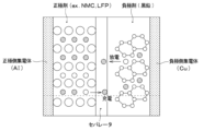
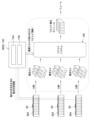
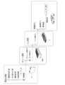
- FIG. 1 is a schematic diagram showing a battery pack to which a battery monitoring device according to a first embodiment is applied; FIG. It is an explanatory view for explaining a lithium ion battery.
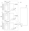
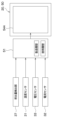
- 1 is a schematic configuration diagram of a battery management unit including a battery monitoring device; FIG. It is an explanatory view for explaining a battery monitoring device.
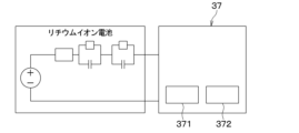
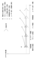
- FIG. 4 is an explanatory diagram for explaining a deposition amount detection unit included in the battery monitoring device; It is an explanatory view for explaining a calculation method of the amount of lithium deposition.
- FIG. 4 is an explanatory diagram for explaining how to obtain a parasitic resistance value;
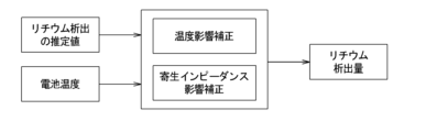
- FIG. 4 is an explanatory diagram for explaining the flow of calculation of the amount of deposited lithium.
- FIG. 4 is an explanatory diagram for explaining diagnosis of a precipitation amount detection unit by a diagnosis unit;
- FIG. 4 is an explanatory diagram for explaining a method of calculating a volumetric ratio SOH of a battery; 4 is a timing chart showing output changes of various sensors before and after occurrence of abnormal heat generation.
- FIG. 4 is an explanatory diagram for explaining the flow of control processing executed by the battery monitoring device;
- 1 is a schematic configuration diagram of a battery management system including a battery monitoring device;
- FIG. 1 is a schematic configuration diagram of a charging system including a battery monitoring device;
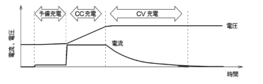
- FIG. 5 is an explanatory diagram for explaining currents and voltages during charging of a battery module in a charging system that is a comparative example of the first embodiment;
- FIG. 4 is an explanatory diagram for explaining the flow of control processing executed by the battery monitoring device when charging of a battery module is started;
- FIG. 4 is an explanatory diagram for explaining the flow of control processing executed by the charger;
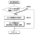
- FIG. 4 is an explanatory diagram for explaining the flow of control processing executed by the battery monitoring device during charging of the battery module;
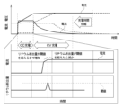
- FIG. 4 is an explanatory diagram for explaining currents and voltages during charging of a battery module in the charging system of the first embodiment;
- 1 is a schematic configuration diagram of a battery evaluation system;
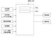
- FIG. FIG. 2 is a schematic block diagram for explaining the value calculation and usage proposal of a battery module by the battery evaluation system;
- FIG. 4 is an explanatory diagram for explaining rebuild information generated by the battery evaluation system;
- FIG. 4 is an explanatory diagram for explaining a manufacturing process up to mounting the battery pack on a vehicle;
- FIG. 7 is an explanatory diagram for explaining some functions of the battery monitoring device according to the second embodiment;
- FIG. 4 is an explanatory diagram for explaining when lithium is deposited in a lithium ion battery;
- FIG. 11 is a schematic configuration diagram of a large-capacity power storage system according to a third embodiment; It is an explanatory view for explaining an internal configuration of a large-capacity electricity storage system.
- 1 is a schematic system configuration diagram of a large-capacity power storage system;
- FIG. 11 is an explanatory diagram for explaining temperature control of a large-capacity power storage system that is a comparative example of the third embodiment; It is an explanatory view for explaining temperature control of a large-capacity electricity storage system concerning a 3rd embodiment. It is an explanatory view for explaining a modification of temperature control.
- FIG. 4 is an explanatory diagram for explaining a time suitable for battery replacement;
- FIG. 4 is an explanatory diagram for explaining the relationship between the charging rate, temperature, and the amount of deposited lithium; It is a schematic block diagram of the battery transportation equipment which concerns on 4th Embodiment.
- 1 is a schematic system configuration diagram of a battery transportation device; FIG.
- the BMU has a battery pack 1 shown in FIG.
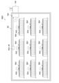
- the battery pack 1 includes a sealed container 11 forming an outer shell, and a plurality of battery modules BM, a battery monitoring device 20, and a battery ECU 100 are housed inside the sealed container 11 .
- the sealed container 11 is provided with a high-pressure protection valve HPV for discharging the gas inside to the outside when the internal pressure increases.
- HPV high-pressure protection valve
- each battery module BM is adjusted to an appropriate temperature by a temperature controller (not shown).
- the plurality of battery modules BM is a power supply that is connected to electrical equipment such as an electric motor (not shown) for running the vehicle and supplies power to the electrical equipment.
- a plurality of battery modules BM are electrically connected in series.
- the plurality of battery modules BM is an assembled battery in which a plurality of battery cells C are electrically connected in series.
- the battery pack 1 including three battery modules BM is illustrated in the present embodiment, the number of battery modules BM is not limited to this, and can be any number.
- the number of battery cells C constituting the battery module BM can also be an arbitrary number.
- a part of the battery modules BM may be electrically connected in parallel.
- the battery cells C and the battery modules BM may be simply referred to as batteries.
- the battery module BM of this embodiment is a storage battery including a lithium ion battery.
- the battery cell C is a rechargeable secondary battery.
- the battery cell C is composed of a lithium ion battery.
- Lithium ion batteries for example, as shown in FIG. 2, are configured by employing lithium iron phosphate LFP or nickel-manganese-cobalt NMC as a positive electrode agent and graphite as a negative electrode agent.
- the positive electrode side current collector is made of aluminum and the negative electrode side current collector is made of copper.
- a lithium-ion battery constructed in this way has excellent charge-discharge cycle characteristics, but the electrode potential is very close to the deposition potential of lithium, and lithium is easily deposited in a charged state.
- the battery monitoring device 20 is electrically connected to each battery module BM via a connection member 21 .
- the connection member 21 includes a flexible substrate FPC on which a wiring pattern is printed.
- the battery monitoring device 20 includes the same number of sensor units 30A, 30B, 30C as the battery modules BM, and the same number of monitoring modules 50A, 50B, 50C as the battery modules BM. Since the sensor units 30A, 30B, and 30C have the same basic configuration, they will be collectively described as the sensor unit 30 instead of being described individually. Also, since the monitoring modules 50A, 50B, and 50C have the same basic configuration, they will be collectively described as the monitoring module 50 instead of being described individually.
- the sensor unit 30 detects the battery state of each battery module BM.
- the sensor section 30 includes a temperature sensor 31, a current sensor 32, a voltage sensor 33, a strain sensor 34, a gas sensor 35, a pack internal pressure sensor 36, a deposition amount detection section 37, and a film detection section 38.
- At least some of the various sensors that constitute the sensor section 30 are mounted on the flexible substrate FPC. It should be noted that not all of the various sensors forming the sensor section 30 need to be mounted on the flexible substrate FPC. However, since the temperature sensor 31, the strain sensor 34, and the gas sensor 35 are preferably located near the battery cell C, it is desirable to mount them on the flexible substrate FPC.
- the temperature sensor 31 is a sensor that detects the battery temperature of the lithium ion battery.
- a plurality of temperature sensors 31 are mounted on the flexible substrate FPC, as shown in FIG.
- the flexible substrate FPC is mounted with temperature sensors 31 the same number as the battery cells C or slightly less than the battery cells C so that the battery temperatures of all the lithium-ion batteries constituting the battery module BM can be grasped.
- the battery temperature may be estimated from the measurement result of the internal impedance of the battery cell C.
- the means for estimating the battery temperature functions as the temperature sensor 31 .
- the current sensor 32 is a sensor that detects current flowing through the battery module BM. If each battery module BM is electrically connected in series, one current sensor 32 in the battery pack 1 is sufficient.
- the voltage sensor 33 can detect the voltage of the battery module BM as a block voltage in addition to the function of detecting the cell voltage of each battery cell C.
- the voltage sensor 33 can be composed of, for example, a flying capacitor type circuit that sequentially charges a capacitor with the cell voltage of each battery cell C and detects the voltage between the terminals of the capacitor as the cell voltage.
- the strain sensor 34 is a sensor that detects strain in each battery cell C caused by gas generation inside each battery cell C or the like.
- the strain of the battery cell C may be detected by another sensor such as an ultrasonic sensor instead of the strain sensor 34 .
- the gas sensor 35 is a sensor for detecting gas leakage from each battery cell C.
- the gas sensor 35 is configured to be capable of detecting at least one of hydrogen, carbon monoxide, carbon dioxide, and hydrogen fluoride, which are generated when, for example, the lithium ion battery malfunctions.
- the pack internal pressure sensor 36 is a sensor that detects the pressure inside the sealed container 11 of the battery pack 1 as the pack internal pressure.
- the pack internal pressure sensor 36 is composed of, for example, an atmospheric pressure range type pressure sensor based on the atmospheric pressure.
- the deposition amount detection unit 37 is a device that detects lithium deposition in the lithium ion battery.
- the deposition amount detection unit 37 uses the correlation between the lithium deposition amount in the lithium ion battery and the behavior of the current and voltage when both ends of the lithium ion battery are short-circuited, and determines the lithium deposition amount from the behavior. presume.
- the deposition amount detection unit 37 detects a short circuit 371 that temporarily short-circuits both ends of the lithium ion battery to discharge it, and a current and voltage when the lithium ion battery is short-circuited by the short circuit 371. It has a calculator 372 for estimating the lithium deposition amount based on the behavior.
- the short circuit 371 is mounted on the flexible substrate FPC. Also, the calculator 372 is mounted on the monitoring module 50 .
- the short circuit 371 has a short circuit switch, a coil, and a capacitor for shorting both ends of the lithium ion battery.
- a self-resonant circuit is configured by the internal resistance of the lithium ion battery, the coil of the short circuit 371, and the capacitor.
- the arithmetic unit 372 extracts a resistance change component correlated with the lithium deposition amount included in the signal waveform of at least one of the current and voltage flowing through the short circuit 371 when both ends of the lithium ion battery are short-circuited, An estimated value of the lithium deposition amount is calculated from the extracted components.
- the above estimation method has a very simple configuration, and is a very useful method in that it can detect specific battery deterioration modes by adjusting the discharge frequency from the lithium-ion battery.
- the internal resistance of lithium-ion batteries is on the order of several m ⁇ to several hundred m ⁇ , and is easily affected by disturbances such as temperature and parasitic impedance. I found it difficult. This was found out after the inventors' intensive studies.
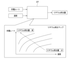
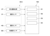
- the computing unit 372 of the precipitation amount detection unit 37 pre-stores the above estimated value in the storage unit 51 of the battery temperature detected by the temperature sensor 31 and the monitoring module 50, as shown in FIG. A corrected value corrected by both of the parasitic resistance values thus obtained is calculated as the lithium deposition amount.
- the parasitic resistance value is part of the parasitic impedance that occurs between the lithium ion battery and the short circuit 371.
- the parasitic resistance value changes according to the battery temperature. Therefore, the computing unit 372 corrects the parasitic resistance value stored in the storage unit 51 according to the battery temperature, and calculates the lithium deposition amount using the corrected parasitic resistance value.
- the calculator 372 also functions as calibration means for correcting the estimated value of the amount of deposited lithium.
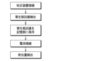
- the parasitic resistance value is obtained by connecting the precipitation amount detection unit 37 to a calibration device CD having a known impedance Z before connecting it to the lithium ion battery.
- the short circuit 371 is connected to the calibrating device CD, and the parasitic resistance value is obtained in this state. Then, the parasitic resistance value is stored in the storage unit 51 of the monitoring module 50 . Next, the short circuit 371 is connected to the battery module BM, and the lithium deposition amount is calculated in this state.
- the precipitation amount detection unit 37 configured in this manner can ensure robustness against parasitic impedance and temperature changes. This is very effective in accurately detecting the amount of deposited lithium.
- the short circuit 371 of the present embodiment includes a coil and has a large physique, so it is necessary to appropriately reduce the size in consideration of mountability. Downsizing can be achieved, for example, by improving the saturation magnetic flux density of the coil. Specific means for miniaturization include, for example, using a coil made of a material with a high magnetic flux density and improving the saturation magnetic flux density by providing a gap.
- the coating detection unit 38 detects the thickness of the coating formed at the interface between the negative electrode and the electrolyte during charging of the lithium ion battery.
- This coating is also called the SEI layer.
- SEI is an abbreviation for Solid Electrolyte Interphase.
- the thickness of the SEI layer has a correlation with current and voltage behavior when both ends of the lithium-ion battery are short-circuited with a short circuit 371.
- the film detection unit 38 estimates the thickness of the SEI layer from the current and voltage behavior when both ends of the lithium ion battery are short-circuited by the short circuit 371 .
- the coating detection unit 38 detects the correlation between the thickness of the SEI layer included in the signal waveform of at least one of the current and voltage flowing through the short-circuit 371. extract a certain component, and estimate the thickness of the SEI layer from the extracted component. It should be noted that when detecting the thickness of the SEI layer, it is desirable to correct the thickness using the battery temperature, as in the case of detecting the amount of deposited lithium.
- the amount of deposited lithium and the thickness of the SEI layer are physical quantities that have a higher correlation with battery capacity deterioration than battery voltage and current.
- the deposition amount detection unit 37 and the film detection unit 38 constitute a "deterioration detection unit” that detects a physical quantity that has a higher correlation with battery capacity deterioration than battery voltage and current.
- the amount of deposited lithium is one of the factors leading to abnormal heat generation in which the temperature of the battery continues to rise unintentionally.
- the precipitation amount detection unit 37 constitutes a "factor monitoring unit” that monitors factors leading to the abnormal heat generation phenomenon.
- the flexible substrate FPC is mounted with a battery state detection unit 39 that detects the battery state. For example, based on the sensor outputs of the temperature sensor 31, the current sensor 32, and the voltage sensor 33, the battery state detection unit 39 detects a battery state in which the battery temperature is excessive, a battery state in which the battery is overcharged, and a battery state in which the internal resistance is large. Detects changing battery status, etc.
- the monitoring module 50 is a satellite module attached directly to the battery module BM.
- the monitor module 50 is the device on the high voltage side of the BMU.
- the monitoring module 50 constitutes an "abnormality detection unit" that is electrically connected to the battery and detects an abnormality in the battery.
- the monitoring module 50 includes a storage unit 51, a wireless communication unit 52, an internal resistance detection unit 53, a monitoring IC 54, and the like.
- the storage unit 51 stores various types of information such as a unique ID set for each monitoring module 50, the monitoring result of the battery module BM, the aforementioned parasitic resistance value, and the like.
- the storage unit 51 is composed of a non-transitional substantive storage medium.
- the wireless communication unit 52 is a communication device for enabling two-way communication with the battery ECU 100.
- the monitoring module 50 receives various signals from the battery ECU 100 and transmits monitoring results of the monitoring module 50 and the like to the battery ECU 100 .
- the internal resistance detection section 53 is a device that detects the internal resistance of the battery based on various information output from the sensor section 30 . Also, a change in the internal resistance of the battery is one of the factors leading to abnormal heat generation. Therefore, the internal resistance detection section 53 constitutes a "factor monitoring section" that monitors factors leading to abnormal heat generation.
- the monitoring IC 54 is electrically connected to the battery to detect battery abnormalities.
- the monitoring IC 54 suppresses the occurrence of the abnormal heat phenomenon based on the results of monitoring factors that lead to the abnormal heat phenomenon, detects an abnormal state that occurs in the battery at the initial stage of the occurrence of the abnormal heat phenomenon, and monitors the abnormal state detection result.
- the monitoring IC 54 includes an ASIC circuit having an algorithm that performs at least part of the monitoring of factors leading to abnormal heat generation and the detection of an abnormal state that occurs in the battery at the initial stage of occurrence of the abnormal heat generation.
- the monitoring IC 54 is configured to have a diagnostic section 541, an SOH estimating section 542, and a monitoring control section 543 as functional sections for executing various controls.
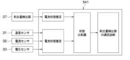
- Diagnosis section 541 compares a predetermined battery state estimated from the amount of deposited lithium with a battery state estimated from factors other than the amount of deposited lithium to diagnose suitability of deposition amount detection section 37 .
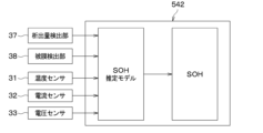
- the diagnostic unit 541 estimates the volumetric ratio SOH of the battery from the lithium deposition amount detected by the deposition amount detection unit 37, as shown in FIG. Moreover, the diagnosis unit 541 estimates the volumetric ratio SOH of the battery based on the sensor outputs of the temperature sensor 31 , the current sensor 32 , and the voltage sensor 33 .
- SOH is an abbreviation for State of Health.
- the diagnosis unit 541 compares the volume ratio SOH estimated from the amount of lithium deposition with the volume ratio SOH estimated from the temperature, current, and voltage of the battery using a state comparator, Diagnose suitability. For example, if the discrepancy between the volume ratio SOH estimated from the lithium deposition amount and the volume ratio SOH estimated from the temperature, current, and voltage of the battery is within a predetermined range, the diagnosis unit 541 determines that the deposition amount detection unit 37 is appropriate. Diagnose.
- the diagnosis unit 541 determines that the deposition amount detection unit 37 is diagnosed as unsuitable.
- the monitoring IC 54 prohibits the detection of the amount of lithium deposition and control processing using the amount of lithium deposition, or detects the failure of the deposition amount detection unit 37 via the wireless communication unit 52. to the battery ECU 100.
- the battery volume ratio SOH was exemplified as the battery state estimated by the diagnostic unit 541, but the diagnostic unit 541 may estimate a battery state other than the volume ratio.
- Japanese Patent Application Laid-Open No. 2014-102076 discloses a method for calculating the fully charged amount of the battery.
- the current value of the output current of the battery is time-integrated to calculate the amount of change in charge/discharge amount between the first point in time and the second point in time.
- the OCV at the first time point and the second time point are measured, the SOC-OCV curve is used to calculate the remaining capacity SOC at the first time point and the second time point, and the deviation of the remaining capacity SOC at each time point is calculated.
- a change amount ⁇ SOC calculated as follows is calculated.
- the full charge amount of the battery is calculated by dividing the amount of change in charge/discharge amount by the amount of change ⁇ SOC in remaining capacity SOC. Further, the volume ratio SOH of the battery is obtained by dividing the full charge amount of the battery by the initial value of the full charge amount.
- the method of calculating the remaining capacity SOC and the volume ratio SOH described above does not calculate the charge/discharge amount of the battery unless there is a scene in which a certain amount of charge or discharge occurs. It cannot be calculated, lacks real-time performance, and has problems in practicality. There is also a problem that the calculation error of the volume ratio SOH increases with time due to the offset error of the current sensor 32 when calculating the charge/discharge amount.
- the SOH estimating unit 542 estimates the volumetric ratio SOH of the battery based on a physical quantity that has a higher correlation with the deterioration of the capacity of the battery than the voltage and current of the battery.
- the SOH estimator 542 constitutes a "volume ratio estimator”.
- the internal resistance of a battery has a strong correlation with physical quantities such as the amount of lithium deposition and the internal resistance of the battery. Also, the internal resistance of the battery is temperature dependent and affects the current and voltage of the battery.
- the SOH estimating unit 542 of the present embodiment estimates the rate SOH.
- the model for estimating the volume ratio SOH is, for example, a control map or a function that defines the relationship between the volume ratio SOH, the lithium deposition amount, the thickness of the SEI layer, the temperature of the battery, the current, and the voltage.
- the estimation model may be, for example, a model obtained by deep learning, reinforcement learning, or deep reinforcement learning using a neural network.
- the monitoring control unit 543 suppresses the occurrence of the abnormal heat phenomenon based on the monitoring results of the factors leading to the abnormal heat phenomenon, detects an abnormal state that occurs in the battery at the initial stage of occurrence of the abnormal heat phenomenon, and controls the abnormal state. Implement countermeasures against abnormal heat generation based on the detection results.
- the monitoring IC 54 controls a circuit for equalizing the voltages of the plurality of battery cells C, and the like.
- the battery ECU 100 is a main module in the BMU and controls charging and discharging of each battery module BM.
- the battery ECU 100 is a device on the low voltage side of the BMU.
- the battery ECU 100 is configured by a microcomputer including a processor, memory, I/O, wireless communication device 110, and the like.
- the battery ECU 100 is configured to be able to communicate with each monitoring module 50A, 50B, 50C via the wireless communication device 110 .
- the battery ECU 100 is connected to various ECUs via communication paths such as CAN. Examples of various ECUs include a heat management ECU for controlling a battery temperature control device, an ECU for an HMI device mounted on a vehicle, and the like.
- the battery ECU 100 can notify the outside of various battery states via an HMI device or the like.
- the battery pack 1 configured in this manner includes a chargeable/dischargeable battery such as a lithium ion battery.
- a chargeable/dischargeable battery such as a lithium ion battery.
- a specific member inside the battery generates heat for some reason, and that heat generation further causes other members to heat up.
- the thermal reliability of the battery is significantly lowered, which is not preferable. Therefore, it is important for lithium ion batteries and the like to ensure thermal reliability by detecting the presence or absence of abnormal heat generation in the battery.
- FIG. 11 shows an example of the results of verification by the inventors of the output changes of various sensors before and after an abnormal heat generation phenomenon.
- the battery volume starts to change due to an increase in the gas pressure inside the battery cell.
- the output of the strain sensor 34 tends to increase.
- the battery breaks and the gas inside the battery cell begins to leak.
- the output of the gas sensor 35 tends to increase.
- the gas pressure inside the battery decreases and the output of the strain sensor 34 tends to decrease.
- the battery monitoring device 20 executes control processing for preventing and early detection of abnormal heat generation.
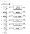
- An example of control processing executed by the battery monitoring device 20 will be described below with reference to FIG. 12 .
- the control process shown in FIG. 12 is executed by the battery monitoring device 20 periodically or irregularly, for example, while the vehicle is starting up and until a predetermined period of time has elapsed since the vehicle was stopped.
- Each processing shown in this flowchart is implemented by each functional unit of the battery monitoring device 20 . Further, each step for realizing this processing can also be grasped as each step for realizing the battery monitoring method.
- the battery monitoring device 20 reads various signals from the sensor section 30 and the like in step S100. Then, in step S105, the battery monitoring device 20 determines whether or not an abnormal heat generation phenomenon has occurred. As described above, in the initial stage of abnormal heat generation, the battery temperature, the pack internal pressure, and the output of the gas sensor 35 rapidly increase, and the battery voltage rapidly drops. Taking this into consideration, the battery monitoring device 20 determines whether or not an abnormal heat generation phenomenon has occurred based on at least some of the sensor outputs of the temperature sensor 31, the voltage sensor 33, the gas sensor 35, and the pack internal pressure sensor 36.
- the battery monitoring device 20 proceeds to step S110 and takes measures against the abnormal heat generation phenomenon.
- This countermeasure includes external notification processing for informing the outside of the occurrence of the abnormal heat phenomenon, and battery protection processing by at least one of battery cooling and charge/discharge control.
- a signal indicating the occurrence of an abnormal heat generation phenomenon is output to the battery ECU 100, and a device having a notification function such as an HMI device is operated via the battery ECU 100 to inform the user or battery manager of the abnormal heat generation phenomenon. to notify the occurrence of
- a signal instructing battery cooling is output to the battery ECU 100, and the temperature control device for the battery is operated via the battery ECU 100 to cool the battery.
- Such battery cooling makes it possible to delay the progress of abnormal heat generation in the battery.
- a signal instructing restriction of charging and discharging of the battery is output to the battery ECU 100 to restrict battery operation, thereby suppressing self-heating of the battery.
- charge/discharge control also makes it possible to delay the progress of abnormal heat generation in the battery.
- the battery protection process constitutes an extension process that extends the life of the battery.
- the battery monitoring device 20 detects an abnormality in a plurality of battery cells C based on at least one of the monitoring result of each of the plurality of battery cells C and the detection result of an abnormal state of the battery. are identified as abnormal cells. According to this, it is possible to limit the use of abnormal cells and delay the progress of abnormal heat generation.
- countermeasures against abnormal heat generation are not limited to the above processes, and may be realized by processes other than those described above.
- Countermeasures against the abnormal heating phenomenon may be, for example, turning on a warning light or sounding an alarm.
- step S115 the processing after step S115 is processing for preventing occurrence of an abnormal heat generation phenomenon.
- step S115 the battery monitoring device 20 determines whether overcharging of the battery has been detected. Overcharging of the battery can be detected by monitoring the sensor output of the voltage sensor 33, for example. When overcharging of the battery is detected, the battery monitoring device 20 executes charging suppression processing in step S120, and returns to step S115. In this charging suppression process, charging of the battery is suppressed or the battery is discharged.
- the battery monitoring device 20 determines in step S125 whether an excessive temperature rise of the battery has been detected. Excessive temperature rise of the battery can be detected by monitoring the sensor output of the temperature sensor 31, for example. When the excessive temperature rise of the battery is detected, the battery monitoring device 20 performs output limitation and cooling control in step S130, and returns to step S115. In the output limitation, for example, battery charge/discharge is suppressed. In cooling control, for example, the battery is cooled by a battery temperature control device.
- the battery monitoring device 20 determines in step S135 whether lithium deposition has been newly detected.
- Lithium deposition can be detected, for example, by monitoring the amount of increase in the amount of lithium deposition detected by the deposition amount detection unit 37 .
- the battery monitoring device 20 When lithium deposition is newly detected, the battery monitoring device 20 performs charging, regeneration control, and heating control in step S140, and returns to step S115.
- charging/regenerative control for example, battery charging is suppressed.
- heating control for example, the battery is warmed by a battery temperature control device.
- the battery monitoring device 20 determines in step S145 whether or not a change in internal resistance of the battery has been detected.
- the internal resistance of the battery can be detected, for example, by monitoring the increase in internal resistance detected by the internal resistance detector 53 .
- the battery monitoring device 20 When a change in the internal resistance of the battery is detected, the battery monitoring device 20 performs battery output limitation, temperature control, and notification of the degree of deterioration in step S150, and returns to step S115.
- output control for example, battery discharge is suppressed.
- temperature regulation control for example, the battery temperature is adjusted by a temperature regulation device so that the battery temperature is maintained within an appropriate range.
- notification of the degree of deterioration the degree of deterioration of the battery is determined from the internal resistance of the battery, and the determination result of the degree of deterioration or the time to replace the battery estimated from the determination result is notified to the outside.
- Each process performed when a change in internal resistance is detected constitutes an extension process for extending the life of the battery.
- the battery monitoring device 20 determines in step S155 whether or not deformation of the battery has been detected. Deformation of the battery can be detected by monitoring the sensor output amount of the strain sensor 34 .
- the battery monitoring device 20 limits the output of the battery in step S160, and returns to step S115. In output control, for example, battery charge/discharge is suppressed.
- the battery monitoring device 20 terminates the control process shown in FIG. 12 .
- the battery monitoring device 20 of the present embodiment can obtain the remaining capacity SOC and volume ratio SOH in real time. Taking this into consideration, it is desirable to use the battery module BM and the battery monitoring device 20 as a battery unit UT, and distribute the market in units of the battery unit UT. And it is desirable to manage the battery module BM by, for example, a battery management system BMS shown in FIG.
- the battery management system BMS includes a battery monitoring device 20 and a battery management device 60 attached to the battery module BM.
- Battery management device 60 includes performance determination unit 61 , value setting unit 62 , and performance notification unit 63 .
- the performance determination unit 61 determines whether secondary use of the battery is possible based on the volumetric ratio SOH estimated by the SOH estimation unit 542 of the battery monitoring device 20 . For example, if the floor area ratio SOH estimated by the SOH estimating unit 542 is equal to or greater than a predetermined value, the performance determination unit 61 determines that secondary use is permitted, and if it is less than the predetermined value, secondary use is not permitted. Note that the performance determination unit 61 may determine whether or not the secondary use of the battery is possible based on the battery state other than the volume ratio SOH.
- the value setting unit 62 determines whether there is an abnormality in the battery based on the volumetric ratio SOH estimated by the SOH estimation unit 542 of the battery monitoring device 20, and sets the residual value of the battery when there is an abnormality in the battery. .
- the value setting unit 62 for example, underestimates the remaining value of the battery as the volumetric ratio SOH decreases. Note that the value setting unit 62 may set the residual value of the battery based on the battery state other than the volumetric ratio SOH.
- the performance notification unit 63 determines whether the volume ratio SOH estimated by the SOH estimation unit 542 of the battery monitoring device 20 is within the allowable range of the volume ratio SOH indicated in the battery specification data, and notifies the result of this determination to an external device. output to
- the performance notification unit 63 acquires battery specification data provided by the battery manufacturer or the like and stores it in the memory. Then, for example, when the floor area ratio SOH estimated by the SOH estimating unit 542 is within the allowable range indicated by the specification data, the performance notification unit 63 notifies the battery distributor, the secondary user, etc. to that effect. . Further, for example, when the volume ratio SOH estimated by the SOH estimation unit 542 is out of the allowable range shown in the specification data, the performance notification unit 63 notifies the battery dealer that the secondary use of the battery is difficult. Notify secondary users, etc.
- the battery monitoring device 20 and the battery monitoring method monitor factors leading to abnormal heat generation, and prevent the occurrence of abnormal heat generation based on the monitoring results of the factors.
- the battery monitoring device 20 and the battery monitoring method detect an abnormal state occurring in the battery at an early stage of occurrence of the abnormal heat generation phenomenon, and take countermeasures against the abnormal heat generation phenomenon based on the detection result of the abnormal state. According to this, it is possible to prevent the occurrence of an abnormal heat generation phenomenon, and even if an abnormal heat generation phenomenon occurs, it is possible to implement effective countermeasures against heat, such as implementing countermeasures from the initial stage of occurrence.
- the battery monitoring device 20 has the following effects.
- the monitoring module 50 of the battery monitoring device 20 monitors factors leading to abnormal heat generation and detects an abnormal state of the battery in parallel. In other words, the monitoring module 50 detects an abnormal state of the battery regardless of the monitoring results of the factors leading to the abnormal heat phenomenon. According to this, an abnormal state can be detected earlier than, for example, when an abnormal state is detected after monitoring factors leading to an abnormal heat generation phenomenon, so countermeasures against the abnormal heat generation phenomenon can be implemented early. can.
- Countermeasures against abnormal heat generation include external notification processing to inform the outside of the occurrence of abnormal heat generation, or battery protection processing by at least one of battery temperature adjustment control and charge/discharge control.
- external notification processing is included in measures against abnormal heat generation, in addition to measures that can be taken by the battery monitoring device 20 itself, measures by external devices of the battery monitoring device 20 or measures in cooperation with external devices can be easily implemented. . Also, if battery protection processing is included in measures against abnormal heat generation, the battery can be appropriately protected.
- the monitoring module 50 performs an extension process for extending the life of the battery according to the monitoring result of the factor of the abnormal heat phenomenon. In this way, if the battery life extension process is executed according to the monitoring result of the factor leading to the abnormal heat generation phenomenon, the battery life can be appropriately extended.
- Factors leading to abnormal heat generation include at least one of lithium deposition inside the battery and internal resistance of the battery. Deposition of lithium inside a lithium-ion battery and an increase in internal resistance are factors that cause an abnormal heat generation phenomenon in the battery. Therefore, by monitoring the deposition of lithium and the internal resistance, it becomes easier to prevent the occurrence of abnormal heat generation in the battery.
- the monitoring module 50 identifies an abnormal cell in the plurality of battery cells C as an abnormal cell based on at least one of the monitoring results of each of the plurality of battery cells C and the detection result of the abnormal state of the plurality of battery cells C. Identify. In this way, with a configuration that can identify an abnormal cell from among a plurality of battery cells C, for example, the use of abnormal cells is restricted to prevent the occurrence of an abnormal heat generation phenomenon, or to prevent the abnormal heat generation phenomenon from progressing. can be delayed.
- the monitoring module 50 is configured to be able to detect at least one of abnormal battery conditions, such as abnormal internal pressure of the sealed container 11, abnormal battery temperature, abnormal battery voltage, and abnormal gas in the sealed container 11.
- abnormal battery conditions such as abnormal internal pressure of the sealed container 11, abnormal battery temperature, abnormal battery voltage, and abnormal gas in the sealed container 11.
- the internal pressure of the sealed container 11 containing the battery, the temperature of the battery, the voltage of the battery, and the gas state in the sealed container 11 become abnormal. Therefore, if the monitoring module 50 is configured to be able to detect at least one of abnormal internal pressure of the sealed container 11, abnormal battery temperature, abnormal battery voltage, and abnormal gas in the sealed container 11, the abnormal heat generation phenomenon can be detected. Easier to detect in the early stages of development.
- the battery monitoring device 20 includes an ASIC circuit having an algorithm that performs at least part of monitoring of factors leading to abnormal heat generation and detection of an abnormal state of the battery. According to this, it is possible to monitor factors leading to abnormal heat generation and detect abnormal conditions with a simple configuration.
- the monitoring module 50 can determine the degree of deterioration of the battery based on the results of monitoring factors leading to abnormal heat generation, and notify the outside of the determination result of the degree of deterioration or the battery replacement time estimated from the determination result. is configured to In this way, if the degree of deterioration of the battery is determined from the results of monitoring the factors leading to the abnormal heat generation phenomenon, a dedicated device for determining the degree of deterioration of the battery is not required. This contributes to simplification of the battery monitoring device 20 .
- connection member 21 that connects the battery and the monitoring module 50 includes a flexible substrate FPC on which a part of the sensor section 30 is mounted.
- the deposition amount detection unit 37 of the battery monitoring device 20 calculates an estimated value of the deposition amount of lithium based on changes in at least one of the current and voltage when both ends of the lithium ion battery are short-circuited by the short circuit 371 . Then, the deposition amount detection unit 37 corrects the estimated value of the deposition amount of lithium with the battery temperature. According to this, the influence of the battery temperature included in the estimated value of the lithium deposition amount can be reduced, and the detection accuracy of the lithium deposition amount can be improved, so the reliability of the deposition amount detection unit 37 can be ensured. .
- the deposition amount detection unit 37 corrects the estimated value of the deposition amount of lithium with the parasitic resistance value stored in the storage unit 51 . According to this, the influence of the parasitic impedance included in the estimated value of the deposited lithium amount can be reduced, and the detection accuracy of the deposited lithium amount can be improved, so the reliability of the deposited amount detection unit 37 can be ensured. .
- the deposition amount detection unit 37 corrects the parasitic resistance value stored in the storage unit 51 according to the battery temperature, and calculates the lithium deposition amount using the corrected parasitic resistance value. According to this, the influence of the battery temperature and the parasitic impedance included in the estimated value of the lithium deposition amount can be reduced, and the detection accuracy of the lithium deposition amount can be improved.
- the parasitic resistance value is obtained by connecting the short circuit 371 to a calibration device CD having a known impedance Z before connecting it to the lithium ion battery. According to this, the parasitic resistance value of the precipitation amount detection unit 37 can be obtained with high accuracy. This greatly contributes to improving the detection accuracy of the amount of deposited lithium.
- the battery monitoring device 20 compares a predetermined battery state estimated from the amount of lithium deposition with a predetermined battery state estimated from factors other than the amount of lithium deposition, and determines whether the deposition amount detection unit 37 is appropriate or not.
- a diagnosis unit 541 for diagnosing is provided. According to this, since the reliability of the precipitation amount detection unit 37 can be diagnosed by the diagnosis unit 541, the reliability of the precipitation amount detection unit 37 can be ensured.
- the battery monitoring device 20 is not the same as that described above, and may be partially different from that described above. Moreover, the technical matters described above can be diverted to devices and systems other than in-vehicle devices.
- the battery monitoring device 20 detects a physical quantity that has a higher correlation with battery capacity deterioration than the battery voltage and current, and estimates the volumetric ratio SOH of the battery based on the physical quantity. In this way, if the volume ratio SOH is estimated by a physical quantity that is highly correlated with battery capacity deterioration, there is a need to avoid the influence of errors compared to the case where the volume ratio SOH is obtained from the current and voltage of the battery. Since it is small, the volume ratio SOH can be estimated in a short time. Therefore, according to the battery monitoring device 20 of the present invention, it is possible to grasp the battery state in a practical manner.
- the amount of lithium deposition and the thickness of the SEI layer are physical quantities that directly affect the capacity deterioration of the battery. Therefore, by detecting the amount of deposited lithium and the thickness of the SEI layer and obtaining the volume ratio SOH based on the amount of deposited lithium and the thickness of the SEI layer, it is possible to ensure real-time performance.
- the degree of cracking of the positive electrode active material inside the battery is a physical quantity that directly affects the capacity deterioration of the battery. Therefore, the detection accuracy of the volume ratio SOH can be improved by adopting a configuration in which the volume ratio SOH is determined based on not only the amount of lithium deposition and the thickness of the SEI layer but also the degree of cracking of the positive electrode active material.
- the degree of cracking of the positive electrode active material can be estimated based on the behavior of current and voltage when both ends of the lithium ion battery are short-circuited, or the sensor output of the strain sensor 34 or ultrasonic sensor.
- the amount of deposited lithium and the thickness of the SEI layer in a lithium ion battery are correlated with the behavior of current and voltage when both ends of the lithium ion battery are short-circuited. Taking this into account, the battery monitoring device 20 determines at least the amount of deposited lithium and the thickness of the SEI layer based on changes in at least one of the current and voltage when both ends of the lithium ion battery are short-circuited by the short circuit 371. Calculate one.
- the battery monitoring device 20 corrects at least one of the amount of lithium deposition and the thickness of the SEI layer with the battery temperature. According to this, the influence of the battery temperature included in the estimated value of the lithium deposition amount and the thickness of the SEI layer can be reduced, and the detection accuracy of the lithium deposition amount and the thickness of the SEI layer can be improved.
- the battery management system BMS determines whether secondary use of the battery is possible based on the volume ratio SOH estimated by the SOH estimation unit 542 of the battery monitoring device 20 . This makes it easier to determine which of reuse, rebuild, and recycle should be selected when the battery is to be used for secondary purposes. This greatly contributes to the construction of a battery ecosystem suitable for a recycling-oriented society.
- the battery management system BMS determines whether there is an abnormality in the battery based on the volumetric ratio SOH estimated by the SOH estimation unit 542 of the battery monitoring device 20. set. This also makes it easier to determine which of reuse, rebuild, and recycle should be selected when the battery is to be used for secondary purposes, contributing to the construction of a battery ecosystem adapted to a recycling-oriented society.
- the battery management system BMS determines whether the volumetric ratio SOH estimated by the SOH estimating unit 542 of the battery monitoring device 20 is within the allowable range of the volumetric ratio SOH indicated in the battery specification data. Output the result externally. This also makes it easier to decide which of reuse, rebuild, and recycle should be selected when the battery is to be used for secondary purposes.
- the battery management system BMS is not the same as the one described above, and may be partially different from the one described above. Moreover, the technical matters described above can be diverted to devices and systems other than in-vehicle devices.
- the charging system BCS will be described below with reference to FIGS. 14 to 19.
- the charging system BCS is a system for charging the battery modules BM included in the battery pack 1 .
- the charging system BCS is applied, for example, to a charging station for vehicles.
- the charging system BCS includes a battery monitoring device 20, a battery ECU 100, a charger 120, and a charging cable CC.
- the battery monitoring device 20 and the battery ECU 100 included in the battery pack 1 constitute battery-side equipment that monitors the battery state including the amount of lithium deposited in the lithium-ion battery.
- the battery module BM is connected to the vehicle's power control unit PCU and motor generator MG via a switch SW2 such as a system main relay. For example, when the start switch of the vehicle is turned on, the switch SW2 is turned on, and the battery module BM is electrically connected to the motor generator MG via the power control unit PCU and becomes chargeable/dischargeable.
- a switch SW2 such as a system main relay.
- the battery monitoring device 20 and the battery ECU 100 are basically configured in the same manner as described above.
- Battery ECU 100 can communicate with charger 120 via communication device CE.
- battery ECU 100 When battery ECU 100 becomes ready to communicate with charger 120 , battery ECU 100 notifies charger 120 of battery information including the battery state such as the lithium deposition amount and remaining capacity SOC. Battery ECU 100 also determines whether or not the battery is in a chargeable state, and notifies charger 120 of the determination result as one piece of battery information. Furthermore, battery ECU 100 sets a CC charging current, which is a target current amount during constant-current charging, and a CV charging voltage, which is a target voltage during constant-voltage charging, and notifies charger 120 of these set values. . Communication between communication device CE and charger 120 is performed via communication lines included in CAN and charging cable CC.
- the charging cable CC electrically connects the battery module BM and the charger 120 .
- the charging cable CC includes a cable, a charging connector (not shown), a control box (not shown), and the like.
- the charger 120 is a device that charges the battery module BM.
- the charger 120 is composed of a device complying with charging standards such as CHAdeMO, CCS, and GB/T.
- a switch SW1 is provided between the charger 120 and the battery module BM to turn on/off electrical connection between the charger 120 and the battery module BM. This switch SW1 may be provided on the charger 120 side, or may be provided on the vehicle side.
- the charger 120 includes an information acquisition unit 121, a charge determination unit 122, a charge control unit 123, and a charge time calculation unit 124.
- the information acquisition unit 121, the charge determination unit 122, the charge control unit 123, and the charge time calculation unit 124 are configured by, for example, a microcomputer having a processor, memory, I/O, and the like.
- the information acquisition unit 121 acquires battery information including the battery state such as the lithium deposition amount and the remaining capacity SOC from the battery monitoring device 20 and the battery ECU 100 when the battery module BM is charged. Information acquisition unit 121 also acquires the CC charging current and the CV charging voltage from battery ECU 100 .
- the lithium deposition amount is important information indicating the safety of the battery module BM.
- the information acquisition unit 121 of this embodiment notifies the outside of the battery information including the information indicating the amount of deposited lithium by the notification device ND.
- the notification device ND is composed of devices such as a display, a speaker, and a lamp, for example.
- the charge determination unit 122 determines whether or not the battery module BM can be charged based on the battery information acquired by the information acquisition unit 121 . For example, the charge determination unit 122 determines whether or not the battery module BM can be charged based on the result of the determination whether the battery ECU 100 is in a chargeable state or not. Note that the charge determination unit 122 may determine whether or not charging is possible based on the amount of lithium deposition and the like acquired by the information acquisition unit 121 .
- the charge control unit 123 charges the battery module BM based on the determination result of the charge determination unit 122 .
- the charge control unit 123 charges the battery module BM when the determination result of the charge determination unit 122 indicates that the battery module BM can be charged, and the determination result indicates that the battery module BM cannot be charged. When indicating that the battery module BM is not charged.
- the charging control unit 123 of this embodiment is configured to charge the battery module BM by a CCCV charging method in which charging is performed at a constant voltage after charging at a constant current.
- CC charging constant-current charging
- CV charging constant-voltage charging
- the charging time calculation unit 124 estimates the required charging time required for charging based on the battery state acquired by the information acquiring unit 121, and notifies the information indicating the estimated required charging time to the outside via the notification device ND.
- the charging time calculator 124 can be configured to estimate the required charging time using, for example, a control map that defines the relationship between the remaining capacity of the battery module BM and the required charging time.
- the notification includes how much the current quick charging is shortened compared to the normal charging. is desirable.
- the charging system BCS configured as described above is required to be capable of high-speed charging with higher energy density. Recently, attempts have been made to shorten the charging time of the battery module BM by supporting 50 kW for the CHAdeMO 1.0 specification, 400 kW for the CHAdeMO 2.0 specification, and 900 kW for the CHAdeMO 3.0 specification on the charger 120 side.
- Charging time can be shortened by increasing charging output, but the increased charging current due to high-output charging accelerates the deposition of lithium on the negative electrode of the battery, which significantly impairs battery life and safety. there is a possibility.
- pre-charging with a small current is performed before CC charging, thereby preventing deterioration and unsafe conditions such as detection of abnormalities such as deep discharge of the battery.
- a charging profile such as
- the charging time will be lengthened accordingly, which may be inconvenient for the user. Also, the user may feel anxious or irritated if the charging time is longer than expected.
- the charging system BCS of the present embodiment is configured such that the charger 120 determines whether or not the battery module BM can be charged based on the battery information acquired from the battery monitoring device 20 and the battery ECU 100 .
- each control step of the control process shown in FIG. 16 constitutes a function implementation unit that implements various functions executed by the battery ECU 100 .
- the battery ECU 100 determines whether or not the charger 120 is connected in step S200. Battery ECU 100 waits until charger 120 is connected, and when charger 120 is connected, the process proceeds to step S210.
- the battery ECU 100 executes initial processing in step S210.
- initial processing the battery ECU 100 initializes flags and the like, and acquires the monitoring results of the battery monitoring device 20 .
- the battery ECU 100 determines whether or not the battery module BM is in a chargeable state. For example, the battery ECU 100 determines that the battery can be charged if the lithium deposition amount is within a predetermined value, and determines that the battery cannot be charged if the lithium deposition amount exceeds the predetermined value. Note that the battery ECU 100 may determine that charging is not possible even when the battery is in an overcharged state or a deep discharged state.
- the battery ECU 100 sets the amount of charge to the battery module BM in step S230.
- the battery ECU 100 obtains the amount of charge to the battery module BM, for example, based on the remaining capacity SOC, volumetric ratio SOH, etc. of the battery module BM.
- Battery ECU 100 also sets the CV charging voltage in step S240.
- the battery ECU 100 sets, for example, a voltage value recommended as the charging voltage of the battery module BM as the CV charging voltage.
- battery ECU 100 sets the CC charging current in step S250.
- the battery ECU 100 for example, sets a current value recommended as the charging current for the battery module BM as the CC charging current.
- battery ECU 100 notifies charger 120 of battery information indicating the battery state including the amount of lithium deposition, various settings including CV charging voltage and CC charging current, and exits this control process.
- the battery ECU 100 notifies the charger 120 in step S270 that the battery module BM cannot be charged, and ends this control process.
- control processing on the charger 120 side when charging the battery module BM will be described with reference to FIG.
- This control process is performed by charger 120 periodically or irregularly.
- each control step of the control process shown in FIG. 17 constitutes a function implementation unit that implements various functions executed by charger 120 .
- charger 120 determines whether or not a notification issued by battery ECU 100 has been received in step S300.
- Charger 120 waits until receiving a notification from battery ECU 100, and upon receiving the notification from battery ECU 100, proceeds to step S310.
- Charger 120 determines whether battery module BM can be charged based on the notification from battery ECU 100 in step S310. It should be noted that the process of step S310 is performed by charging determination unit 122 of charger 120 .
- the charger 120 When the notification from the battery ECU 100 indicates that charging is not possible, the charger 120 outputs information indicating that the battery module BM cannot be charged and information indicating the lithium deposition amount to the outside via the notification device ND in step S320. notifies and does not charge the battery module BM.
- the charger 120 starts CC charging in step S330.
- the charger 120 charges the battery module BM using the CC charging current set by the battery ECU 100 as a target current amount.
- step S340 the charger 120 determines whether or not the voltage of the battery module BM has reached a predetermined voltage. This determination process determines whether or not it is time to switch from CC charging to CV charging.
- the predetermined voltage is set, for example, to the CV charging voltage.
- the charger 120 determines in step S350 whether or not it has received a CC charging current setting update notification from the battery ECU 100 .
- the battery ECU 100 periodically or irregularly executes the setting update process shown in FIG. 18 during CC charging. Specifically, as shown in FIG. 18, battery ECU 100 determines in step S500 whether or not the lithium deposition amount is greater than a predetermined threshold value. This threshold is set to a value that assumes the amount of lithium deposited when the battery is abnormal. Battery ECU 100 skips subsequent steps and exits the setting update process when the lithium deposition amount is equal to or less than the predetermined threshold value, and proceeds to step S510 when the lithium deposition amount is greater than the predetermined threshold value. In step S510, battery ECU 100 resets the CC charging current to be smaller than the current value. Battery ECU 100 resets, for example, the current value before the amount of lithium deposition exceeds a predetermined threshold as CC charging current. Then, in step S520, battery ECU 100 notifies charger 120 of the setting update of the CC charging current.
- a predetermined threshold value is set to a value that assumes the amount of lithium deposited when the battery is abnormal. Battery E
- step S360 when the charger 120 receives the CC charging current setting update notification from the battery ECU 100, the CC charging current is updated to the current amount notified from the battery ECU 100 in step S360. That is, charger 120 reduces the current amount of the constant current when the lithium deposition amount increases beyond a predetermined threshold value during CC charging. Note that the process of step S ⁇ b>360 is performed by charging control unit 123 of charger 120 .
- the charger 120 proceeds to step S370 and starts CV charging.
- the charger 120 charges the battery module BM using the CV charging voltage set by the battery ECU 100 as a target voltage.
- step S380 the charger 120 determines whether or not the current flowing through the battery module BM is equal to or less than a predetermined value, or whether or not the elapsed time from the start of charging the battery module BM is equal to or greater than a predetermined time. do.
- the charger 120 When the current flowing through the battery module BM is greater than a predetermined value and the elapsed time from the start of charging is within the predetermined time, the charger 120 continues CV charging. Further, when the current flowing through the battery module BM is equal to or less than the predetermined value, or when the elapsed time from the start of charging exceeds the predetermined time, the charger 120 executes the charging termination process in step S390, and then executes this control process. Exit. In the charging end process, for example, the completion of charging, the amount of charge, the battery state, etc. are notified to the user by the notification device ND.
- the charging system BCS described above includes a charger 120 for battery modules BM containing lithium ion batteries.
- the charger 120 includes an information acquisition unit 121 that acquires battery information from the battery-side device, a charge determination unit 122 that determines whether the battery module BM can be charged based on the battery information, and a and a charging control unit 123 for charging the battery module BM.
- the charger 120 is configured to determine whether or not the battery module BM can be charged based on the battery information acquired from the battery-side device, it can be determined whether or not the battery module BM can be charged by performing preliminary charging.
- the charging time can be shortened compared to the determination.
- the charging control unit 123 of the charger 120 is configured to charge the battery module BM by a CCCV charging method in which charging is performed at a constant voltage after charging at a constant current. Then, for example, as shown in FIG. 19, the charge control unit 123 reduces the current amount of the constant current when the lithium deposition amount increases beyond a predetermined threshold value during CC charging. According to this, the amount of lithium deposited during CC charging is suppressed, so that the charging time of the battery module BM can be suppressed while ensuring the safety of the battery module BM.
- the battery-side device When charging by the charger 120 is started, the battery-side device periodically determines whether or not the lithium deposition amount has increased beyond the threshold. Then, when the amount of lithium deposition increases beyond the threshold, the battery-side device sets the target current amount during constant-current charging to a value smaller than the current amount of current, and sends the target current amount to the charger 120. Notice.
- the charge control unit 123 adjusts the constant current amount based on the target current amount. In this way, if the battery-side device periodically monitors the amount of lithium deposition and the charger 120 side adjusts the amount of current suitable for charging at a constant current based on the monitoring results, lithium It becomes possible to control the charge rate to maximize it so that no deposition occurs. As a result, it is possible to appropriately shorten the waiting time due to the user's charging time.
- the charger 120 estimates the required charging time required for charging based on the battery state, and notifies the outside of information indicating the estimated required charging time through the notification device ND. According to this, since the user can roughly grasp the waiting time, it is possible to reduce the psychological burden on the user when charging the battery module BM.
- the charger 120 notifies the information indicating the lithium deposition amount to the outside by the notification device ND. In this way, if it is possible to provide the user with not only the information indicating the required charging time but also the information indicating the amount of lithium deposition, the user will be able to grasp the safety of the lithium ion battery. It is possible to reduce user's anxiety.
- the charging system BCS is not the same as that described above, and may differ in part from that described above. Moreover, the technical matters described above can be diverted to devices and systems other than in-vehicle devices.
- lithium may precipitate due to charging at low temperatures or high-speed charging. As lithium deposition progresses, an internal short circuit may occur, leading to ignition and smoke generation. Therefore, when reusing a storage battery including a lithium-ion battery, it is desirable to understand the safety considering not only the degree of deterioration but also the degree of deposition of lithium.
- the battery evaluation system BRS and the battery evaluation method of this embodiment determine the safety of the storage battery based on the lithium deposition amount. Also, the battery evaluation system BRS functions as a support system that supports reuse and rebuilding of the battery module BM. The battery evaluation system BRS and the battery evaluation method will be described below with reference to FIGS. 20 to 22. FIG.
- the battery evaluation system BRS includes a battery monitoring device 20 as a battery monitoring unit that monitors the battery state of the battery module BM, and an evaluation device 130 that evaluates the battery module BM.
- the battery monitoring device 20 is basically configured in the same manner as described above.
- the battery monitoring device 20 is configured to be able to calculate the amount of deposited lithium in the lithium ion battery included in the battery module BM as one index indicating the battery state.
- the battery monitoring device 20 is capable of outputting battery status information including monitoring results of the battery status including the amount of deposited lithium to the outside.
- This battery state information includes, in addition to the amount of lithium deposition, battery form information indicating the application of the battery module BM, usage history of the battery module BM, and the like.
- the battery monitoring device 20 may be configured to output battery state information and the like to the outside by a communication device other than the wireless communication unit 52 of the monitoring module 50 .
- the evaluation device 130 is connected via a wired or wireless communication network to the battery monitoring device 20, a data center in which market trading information of reusable batteries is stored, information terminals UA and UB owned by users, dealers, secondary users, etc. , UC and the like.
- the evaluation device 130 acquires battery state information from the battery monitoring device 20 and evaluates the battery module BM based on the battery state information.
- the evaluation device 130 of this embodiment includes a safety determination unit 131 , a value calculation unit 132 , a usage proposal unit 133 , a reuse determination unit 134 and an information output unit 135 .
- the safety determination unit 131 determines the safety of the battery module BM based on the lithium deposition amount of the lithium ion battery included in the battery module BM. The safety determination unit 131 determines that the safety is higher as the lithium deposition amount is smaller, and that the safety is lower as the lithium deposition amount is larger. If the battery module BM contains even one unsafe lithium battery, the safety of the battery module BM is compromised. Therefore, the safety determination unit 131 can rank the safety of each of the plurality of lithium ion batteries included in the battery module BM based on the lithium deposition amount.
- the value calculation unit 132 calculates the value of the battery module BM in consideration of the safety judgment result of the battery module BM.
- the value calculation unit 132 calculates the value, for example, assuming that the battery module BM with high safety is more expensive than the battery module BM with low safety.
- the value calculation unit 132 acquires the deterioration state based on the volume ratio SOH, the safety based on the lithium deposition amount, the battery form information including the application, and the usage history from the battery monitoring device 20, Acquire market trading information for reused batteries from the data center. Then, the value calculation unit 132 calculates the purchase price of the battery module BM based on the deterioration state, safety, battery form information, usage history, and market trading information.
- the value calculation unit 132 refers to a map that associates, for example, deterioration state, safety, battery form information, usage history, market trading information, and purchase price of the battery module BM, and information obtained from the battery monitoring device 20 and the data center. , the purchase price of the battery module BM is calculated. Note that the value calculation unit 132 may calculate the sales price of the battery module BM.
- the usage proposal unit 133 proposes a transitional usage of the battery module BM during reuse, taking into consideration the determination result of the safety of the battery module BM. For example, as shown in FIG. 21, the application proposal unit 133 proposes recommended applications for reuse of the battery module BM based on the deterioration state, safety, battery type information, and usage history.
- the usage proposal unit 133 refers to, for example, a map that associates the deterioration state, safety, battery form information, usage history, and reuse usage, and based on the information acquired from the battery monitoring device 20, recommends reuse of the battery module BM. Ask for recommended uses of the time.
- the reuse determination unit 134 determines whether or not the lithium ion batteries can be reused, taking into consideration the safety of each of the plurality of lithium ion batteries that make up the battery module BM. For example, the reuse determining unit 134 determines that the battery is reusable if the lithium deposition amount is equal to or less than a predetermined value, and determines that the battery cannot be reused if the lithium deposition amount exceeds the predetermined value.
- the information output unit 135, as shown in FIG. Outputs the combination of lithium-ion batteries as rebuild information.
- the information output unit 135 outputs a combination corresponding to the usage mode of the battery after rebuilding to the rebuilding system RS that manufactures the rebuilding battery.
- the information output unit 135 outputs a combination of long life and high safety as rebuild information, for example, when the usage mode of the batteries after rebuilding is a stationary type or the like that is used for a long period of time. For example, if the rebuilt battery is to be used in a short period of time, the information output unit 135 outputs a combination that emphasizes items other than life as rebuild information.
- the battery evaluation system BRS and the battery evaluation method described above monitor the battery state of the battery module BM, and evaluate the battery module BM based on the battery state information including the battery state monitoring result.
- the battery monitoring device 20 calculates the lithium deposition amount in the lithium ion battery as one index indicating the battery state.
- Evaluation device 130 determines the safety of battery module BM based on the amount of lithium deposition. According to this, since the indicator related to the safety of the battery module BM, such as the lithium deposition state, is determined, it is possible to appropriately perform the evaluation including whether or not the safety requirement is satisfied.
- the battery evaluation system BRS and the battery evaluation method of this embodiment have the following features.
- the evaluation device 130 includes a value calculation unit 132 that calculates the value of the battery module BM in consideration of the safety judgment result of the battery module BM. According to this, it is possible to provide the appropriate value of the battery module BM to the user as information.
- the evaluation device 130 includes a usage proposal unit 133 that proposes a usage of the battery module BM when it is reused, taking into consideration the determination result of the safety of the battery module BM. According to this, it is possible to provide the user with appropriate usage of the battery module BM as information.
- the evaluation device 130 ranks the safety of each of the plurality of lithium ion batteries included in the battery module BM based on the amount of lithium deposition. According to this, it is possible to provide the user with the appropriate state of the plurality of lithium ion batteries that constitute the battery module BM as information.
- the evaluation device 130 includes a reuse determination unit 134 that determines whether the lithium ion batteries can be reused, taking into consideration the safety of each of the plurality of lithium ion batteries. According to this, even if the battery module BM as a whole cannot be reused, it becomes easy to reuse the highly safe lithium ion battery in the battery module BM.
- the evaluation device 130 considers the safety of the lithium-ion battery, A suitable combination of lithium-ion batteries is output as rebuild information. According to this, even if the battery module BM as a whole cannot be reused, it becomes easy to reuse by constructing another storage battery using the highly safe lithium ion battery in the battery module BM.
- the battery state information includes at least one of the usage, usage history, and deterioration state of the lithium ion battery, in addition to the lithium deposition amount. In this way, if the battery module BM is evaluated using various information, multifaceted evaluation of the battery module BM becomes possible.
- the battery evaluation system BRS and the battery evaluation method are not the same as those described above, and may be partially different from those described above. Moreover, the technical matters described above can be diverted to devices and systems other than in-vehicle devices.
- FIG. 23 an example will be described in which the cause of the abnormality of the battery module BM is identified based on the usage history and manufacturing history of the battery module BM.
- the manufacturing process up to mounting the battery pack 1 on the vehicle will be described with reference to FIG.
- the battery pack 1 is mounted on the vehicle through the steps of manufacturing the battery cell C ⁇ manufacturing the battery module BM ⁇ manufacturing the battery pack 1 ⁇ mounting to the vehicle.
- the formation of the electrode assembly, cell assembly, electrolyte injection, initial charge/discharge, and performance inspection are carried out in this order.
- performance inspection for example, an appearance inspection, a foreign substance inspection, a battery characteristic inspection, and the like of the battery cell C alone are performed by inspection equipment.
- lithium ions may be reduced at the negative electrode and deposited.
- the lithium ions released from the positive electrode active material cannot completely enter the negative electrode active material, and the negative electrode surface easily precipitated.
- the amount of lithium ions that contribute to the battery reaction is reduced, which may lead to a decrease in capacity or an internal short circuit.
- the manufacturing process of the battery cell C the current and temperature conditions under which lithium deposition does not occur are calculated and mapped, and manufacturing devises and inspections are carried out so that the battery cell C is not contaminated with metallic foreign matter.
- the manufacturing process of the battery cell C for example, by exposing the electrode surface of the battery cell C to light to inspect whether lithium is deposited, or by measuring the resistance distribution on the surface of the negative electrode active material, lithium deposition Ease of application is inspected.
- module assembly for assembling the battery cells C together and sensor assembly for assembling the sensor unit 30 and the like to the assembly of the battery cells C are performed.
- the battery monitoring device 20 is attached to the battery module BM. As a result, the amount of deposited lithium and the like can be monitored by the battery monitoring device 20 at the manufacturing stage of the battery module BM.
- pack assembly is carried out in which the assembled battery modules BM are accommodated in the sealed container 11. In this step, an inspection such as continuity confirmation is appropriately performed.
- the battery pack 1 is assembled into the vehicle and the vehicle is inspected. In the vehicle inspection, we will check the continuity with the onboard equipment. After that, the vehicle equipped with the battery pack 1 is shipped from the factory to the user.
- the battery monitoring device 20 includes a deposition amount detection unit 37 that calculates the amount of deposited lithium using the output of a sensor installed in the battery module BM, and a time change of the amount of deposited lithium. as one of battery usage histories.
- the battery monitoring device 20 stores, for example, the amount of lithium deposition and the like as one of the usage histories in the storage unit 51, which is a storage medium, when the user is driving the vehicle. In addition, the battery monitoring device 20 stores the amount of lithium deposited in the manufacturing process of the battery module BM, the manufacturing process of the battery pack 1, the vehicle assembly process, etc. as one of the manufacturing histories in the storage unit 51 or an external storage device. .
- the battery monitoring device 20 detects the lithium ion battery based on the usage history stored in the storage unit 51 and the manufacturing history stored in the storage unit 51 or an external storage device.
- An abnormality identification unit 544 is provided to identify the cause of the abnormality.
- the abnormality identification unit 544 uses the manufacturing history as reference data, compares the manufacturing history and the usage history, identifies the time when the abnormality occurred in the lithium ion battery, and verifies the battery state before and after the occurrence time. , to identify the cause of the abnormality in the lithium-ion battery. For example, as shown in FIG. 25, the abnormality identifying unit 544 identifies the timing at which the lithium deposition amount increases as the timing of occurrence of abnormality in the lithium ion battery.
- the battery monitoring device 20 of the present embodiment can obtain the same effects as those of the first embodiment due to the configuration common to or equivalent to that of the first embodiment.
- the battery monitoring device 20 of the present embodiment has the following features.
- the battery monitoring device 20 includes a storage unit 51 that stores the change in the amount of lithium deposition over time as one of the history of use or manufacture of the lithium ion battery.
- the amount of deposited lithium can be detected non-destructively and appropriately in a short period of time, and the state of deposited lithium can be inspected.
- a sensor for detecting deposition of lithium is installed in the battery module BM, the deposition state of lithium can be detected regardless of time and place.
- by storing the temporal change in the amount of deposited lithium in the storage unit 51 as one of the usage history or manufacturing history of the lithium ion battery it is possible to clearly grasp when lithium is deposited. This has the advantage of clarifying where the responsibility for lithium deposition lies.
- the battery monitoring device 20 also has an abnormality identification unit 544 that identifies the cause of the abnormality in the lithium ion battery based on the usage history and the manufacturing history of the lithium ion battery when an abnormality occurs in the lithium ion battery. Prepare. In this way, if it is possible to identify the cause of an abnormality in a lithium-ion battery based on history information, including not only the usage history but also the manufacturing history, the search for the cause of the abnormality can be made not only at the usage stage but also at the usage stage. , can be traced back to the manufacturing stage. This greatly contributes to clarifying where responsibility lies.
- the battery monitoring device 20 of the second embodiment is not the same as the one described above, and may be partially different from the one described above. Also, the technical matters described in the second embodiment can be diverted to devices and systems other than in-vehicle devices.
- FIG. 26 to 33 An example in which the battery management unit BMU of the present disclosure is applied to a stationary large-capacity power storage system BSS will be described.
- the large-capacity power storage system BSS includes a container SC, a plurality of battery modules BM, an air blower CM, a heater device HM, a battery management unit BMU, and the like.
- a plurality of battery modules BM are storage batteries each including a lithium ion battery.
- a sensor unit 30 is installed in each of the plurality of battery modules BM. This sensor section 30 is configured in the same manner as described in the first embodiment.
- the storage container SC is a container that stores a plurality of battery modules BM.
- the storage container SC is appropriately provided with an opening for ensuring air permeability.
- the storage container SC is provided with an air blower CM and a heater device HM.
- the air blower CM is a cooling element for the battery module BM, and generates airflow inside the container SC.
- the air blower CM may be configured as a type of device that sucks air into the container SC, or may be configured as a type of device that pushes air into the container SC.
- the operation of the blower CM is controlled according to a control signal from a battery control device 140, which will be described later.
- the heater device HM is a heating element for the battery module BM, and includes a heating element that generates heat when energized. Heater device HM may be configured to directly heat battery module BM, or may be configured to indirectly heat battery module BM. The operation of the blower CM is controlled according to a control signal from a battery control device 140, which will be described later.
- the battery management unit BMU manages a plurality of battery modules BM.
- the battery management unit BMU includes a sensor section 30 that monitors the battery state including the amount of lithium deposited in the lithium ion battery, and a battery control device 140 that controls charging of the plurality of battery modules BM.
- the battery control device 140 controls charging of the plurality of battery modules BM based on the battery state monitored by the sensor unit 30.
- the battery control device 140 charges the plurality of battery modules BM using, for example, power obtained from solar power generation or the like or power during times when electricity prices are low.
- a notification device ND is also connected to the battery control device 140 .
- the battery control device 140 notifies the battery state and the like monitored by the sensor unit 30 to the outside using the notification device ND.
- the electrode potential during charging decreases to near the oxidation-reduction potential of lithium, so lithium is likely to precipitate in situations such as low-temperature charging, high-capacity charging, and overcharging.
- Lithium deposition reduces the available lithium ions inside the battery, causing rapid battery capacity degradation.
- an internal short circuit may occur, and in the worst case, it may develop into thermal runaway of the battery.
- the electric power stored in the battery is used as the power source, and the battery is heated by a heating element such as the heater device HM. It is conceivable to raise the temperature.
- the above method is a control method that focuses only on the battery temperature, and depending on the charge/discharge rate of the battery, it may not always be necessary to raise the temperature of the battery. Also, if only the temperature of the battery is focused, the temperature of the battery may be excessively controlled, and as a result, the electric power stored in the battery may be excessively used. In addition, in the case of a large-scale power storage facility such as a large-capacity power storage system BSS, the temperature distribution of the battery becomes complicated, and it becomes difficult to properly grasp the temperature of the battery. In addition, it is difficult to detect battery failures such as internal short circuits at an early stage based only on the temperature information of lithium-ion batteries. Downtime may occur. Note that the charge/discharge rate is the speed of charge and discharge.
- the battery control device 140 heats the lithium ion battery according to the amount of lithium deposited during charge control. Note that deposition of lithium may occur at times other than during charge control. For this reason, it is desirable that the battery control device 140 heats the lithium-ion battery in accordance with not only charging control but also the amount of deposited lithium.
- the battery control device 140 starts energizing the heater device HM to heat the battery module BM.
- the heating of the battery module BM reduces the lithium deposition amount.
- the battery control device 140 stops energizing the heater device HM to stop heating the battery module BM.
- deposition of lithium occurs not only during low-temperature charging, but also in situations such as high-capacity charging and overcharging.
- the battery temperature of the battery module BM may be high to some extent.
- the battery control device 140 may heat the lithium ion battery according to the amount of lithium deposition and the temperature of the battery module BM. For example, as shown in FIG. 31, the battery control device 140 controls the heater device HM to to heat the battery module BM.
- the battery control device 140 limits charging and discharging of the battery module BM, or , the abnormality of the battery is notified to the outside.
- the period from when the volume ratio SOH of the battery decreases to some extent due to deterioration until the lithium deposition amount reaches the amount that causes the internal short circuit of the battery It is desirable to replace the battery at
- the battery control device 140 of the present embodiment estimates a desirable battery replacement period from changes in the volumetric ratio SOH output by the sensor unit 30 and changes in the lithium deposition amount, and sets the battery replacement period to the recommended period. , and is notified to the outside by the notification device ND. According to this, since the business operators can know the recommended period for battery replacement, it is possible to reduce downtime due to system failure including maintenance and battery failure.
- the battery management unit BMU of the present embodiment can obtain the same effects as in the first embodiment from the same or equivalent configuration as that of the first embodiment.
- the battery management unit BMU of this embodiment has the following features. (1) The battery management unit BMU heats the battery module BM by the heater device HM that raises the temperature of the battery module BM when the lithium deposition amount increases beyond a predetermined threshold. According to this, the lithium ion battery is heated at the timing when the lithium deposition amount increases, and the increase in the lithium deposition amount is appropriately suppressed, so the lithium ion battery can be used in a safe and highly efficient manner.
- the battery management unit of the present invention is suitable for large-scale power storage facilities where the temperature distribution tends to expand.
- the sensor unit 30 includes a temperature sensor 31 that detects the battery temperature of the lithium ion battery.
- the battery control device 140 may heat the battery module BM with the heater device HM when the lithium deposition amount increases beyond a predetermined threshold and the battery temperature drops below a predetermined low temperature threshold. This also allows the lithium ion battery to be used in a safe and highly efficient manner.
- the battery management unit BMU of the large-capacity power storage system BSS has been described in detail in the third embodiment, the battery management unit BMU is not the same as the one described above, and may be partially different from the one described above. .
- the technical matters described in the third embodiment can be diverted to devices and systems other than the large-capacity power storage system BSS.
- the battery management unit BMU can be diverted, for example, to power management of mobile objects such as vehicles.
- the heating element is composed of the heater device HM, but the present invention is not limited to this, and the heating element may be composed of a load device around the battery. Also, the heating element may be heated by power supply from other than the battery module BM.
- the deposition amount detection unit 37 calculates the deposition amount of lithium with reference to a control map that defines the correlation between the deposition amount of lithium, the charge rate, and the battery temperature, as shown in FIG. 33, for example. It can be like this. This also applies to embodiments other than the present embodiment.
- FIG. 34 a battery transportation device BSC that transports batteries in a storage container SC will be described.
- Lithium-ion batteries also contain toxic and flammable chemicals, so they must be transported safely.
- international regulations stipulate packaging standards according to the lithium content.
- Assembled batteries such as those used in electric vehicles have a high lithium content and are legally difficult to transport by air, and are generally transported by sea by ship.
- sea transportation takes a long time. For example, in summer, the transportation is carried out for a long time under high temperature and humidity conditions, and in winter, the transportation is carried out for a long time under low temperature conditions. Under such a stressful environment, once the lithium-ion battery shifts to an unsafe condition, the lithium-ion battery becomes uncontrollable and may cause damage to other cargo and passengers. It is important to monitor safety conditions.
- the cooling mechanism It is conceivable to deactivate the ion battery.
- the chemical reaction that causes the lithium-ion battery to become unsafe is a chain reaction of exothermic reactions, and when the gas sensor 35 is used to detect an unsafe event in the battery as in the above method, the gas is ejected from the lithium-ion battery.
- the chain reaction has already started. At such a point, it is difficult to deactivate a lithium-ion battery because the chain reaction proceeds rapidly.
- the escaping gas is toxic and can cause damage to the cargo and crew.
- the battery transportation equipment BSC of the present embodiment monitors the factors that lead to the abnormal heat phenomenon in which the temperature of the battery continues to rise unintentionally, and based on the monitoring results, It is configured to be able to detect an abnormal state occurring in the battery.
- the battery transportation equipment BSC includes a storage container SC that houses a plurality of battery modules BM, a sensor section 30A that detects the battery state of the plurality of battery modules BM, and an abnormality detection section 150.
- the sensor section 30A includes a humidity sensor HS and an acceleration sensor GS in addition to the temperature sensor 31, gas sensor 35, and precipitation amount detection section 37 described in the first embodiment.
- the humidity sensor HS is installed inside the storage container SC and detects the humidity inside the storage container SC.
- the acceleration sensor GS is set in the container SC to detect vibrations and shocks applied to the container SC. Note that the sensor unit 30A may include other sensors.
- the sensor unit 30A of this embodiment includes a wireless communication device (not shown) for wirelessly communicating with the abnormality detection unit 150.
- the sensor unit 30A may include a communication device for wired communication with the abnormality detection unit 150 .
- the abnormality detection unit 150 suppresses the occurrence of abnormal heat generation based on the results of monitoring of factors leading to abnormal heat generation, detects an abnormal state that occurs in the battery at the initial stage of occurrence of the abnormal heat generation, and detects the abnormal state. Implement countermeasures against abnormal heat generation based on the results.
- the abnormality detection unit 150 is configured similarly to the monitoring module 50 described in the first embodiment. That is, the abnormality detection unit 150 includes a storage unit 51, a wireless communication unit 52, an internal resistance detection unit 53, a monitoring IC 54, and the like.
- the anomaly detection unit 150 executes the control process shown in FIG. 12 described in the first embodiment in order to prevent and early detect an abnormal heat generation phenomenon.
- the abnormality detection unit 150 performs the external notification process, the battery protection process, and the like described in the first embodiment as countermeasures against the abnormal heat generation phenomenon.
- a signal indicating the occurrence of an abnormal heat generation phenomenon is output to the notification device ND, and the occurrence of the abnormal heat generation phenomenon is notified to the outside via the notification device ND.
- this external notification process for example, at least one of the sensor outputs of the temperature sensor 31, the humidity sensor HS, the acceleration sensor GS, and the positional information of the battery module BM in which the abnormal heat generation phenomenon has occurred is notified to the outside. is desirable. The reason is that it becomes easier to clarify where the responsibility for the occurrence of the abnormal heat phenomenon lies.
- the position information of the battery module BM for example, information specified based on the radio wave intensity of the signal emitted by the sensor unit 30A can be used.
- the battery transportation equipment BSC of the present embodiment can obtain the same effects as those of the first embodiment due to the common configuration or the equivalent configuration of the first embodiment.
- the battery transportation equipment BSC of this embodiment has the following features.
- the battery transportation equipment BSC includes a storage container SC, a factor monitoring unit that monitors factors leading to an abnormal heat generation phenomenon in which the temperature of the battery continues to rise unintentionally, and an abnormality detection unit 150 that detects an abnormality in the battery. , provided. Then, the abnormality detection unit 150 suppresses the occurrence of abnormal heat generation based on the monitoring result of the factor monitoring unit, detects an abnormal state that occurs in the battery at the initial stage of occurrence of the abnormal heat generation, and detects the abnormal state detection result.
- the battery monitoring device 20 of the present invention is essential for detecting the lithium deposition amount of the lithium ion battery by the battery monitoring device 20, but it is not essential for measures against abnormal heat generation of the battery, estimation of the volume ratio SOH of the battery, and the like.
- the amount of lithium deposited and the internal resistance of the battery are monitored as factors leading to the abnormal heat generation phenomenon, but physical quantities other than these are monitored as factors leading to the abnormal heat generation phenomenon. good too.
- a plurality of processes are illustrated as countermeasures against the abnormal heating phenomenon, but the battery monitoring device 20 may carry out some of the processes. Further, measures other than those described above may be used as countermeasures against the abnormal heat generation phenomenon.
- abnormal conditions occurring in the battery at the initial stage of occurrence of abnormal heat generation include abnormal internal pressure of the sealed container 11, abnormal battery temperature, abnormal battery voltage, and abnormal gas in the sealed container 11. It is not limited to this. A battery state other than these may be detected as an abnormal state occurring in the initial stage of occurrence of an abnormal heat generation phenomenon.
- the battery monitoring device 20 described above includes a flexible substrate FPC and an ASIC circuit, it is not limited to this.
- the flexible printed circuit board FPC and ASIC circuit are not essential components in the battery monitoring device 20 .
- the battery monitoring device 20 is preferably adapted to correct the estimated lithium deposition amount by the battery temperature or the parasitic resistance value, but it does not have to be.
- the battery monitoring device 20 compares the predetermined battery state estimated from the lithium deposition amount with the predetermined battery state estimated from other factors, and determines whether the deposition amount detection unit 37 is appropriate. It is desirable to be able to diagnose, but it does not have to be.
- the volume ratio SOH is estimated based on the amount of lithium deposited and the thickness of the SEI layer of the battery, but the volume ratio SOH is estimated based on other physical quantities.
- the battery monitoring device 20 may, for example, detect a deterioration state including cracks in the positive electrode of the battery, and calculate the volumetric ratio SOH based on the deterioration state.
- the battery monitoring device 20 be able to form a battery management system BMS that manages the battery modules BM together with the battery management device 60, but it does not have to be. This also applies to the charging system BCS and the battery evaluation system BRS. Note that the battery evaluation system BRS may be configured as one functional unit in the battery management system BMS.
- the monitoring target of the battery monitoring device 20 is not limited to the vehicle-mounted battery mounted on the vehicle.
- the battery monitoring device 20 can also be used, for example, as a device for monitoring stationary storage batteries and portable storage batteries.
- the battery monitoring device 20 basically monitors lithium-ion batteries, but it is not limited to this, and if there is a battery that can cause the same problem as a lithium-ion battery, the battery can also be monitored. It should be noted that the battery to be monitored by the battery monitoring device 20 does not have to be formed by modularizing a plurality of battery cells C. FIG.
- the battery monitoring device 20 may be connected to the battery ECU 100 not wirelessly, but wiredly.
- the battery monitoring device 20 is not limited to one that completely matches the one described above, and may be partially different from the one described above.
- the controller and techniques of the present disclosure may be implemented on a dedicated computer provided by configuring a processor and memory programmed to perform one or more functions embodied by the computer program. good too.
- the controller and techniques of the present disclosure may be implemented in a dedicated computer provided by configuring the processor with one or more dedicated hardware logic circuits.
- the control unit and method of the present disclosure is a combination of a processor and memory programmed to perform one or more functions and a processor configured by one or more hardware logic circuits. It may be implemented on one or more dedicated computers.
- the computer program may also be stored as computer-executable instructions on a computer-readable non-transitional tangible recording medium.
- a battery monitoring device for monitoring the amount of lithium deposition in a lithium ion battery, a short circuit (371) for temporarily shorting both ends of the lithium ion battery to discharge, based on a change in at least one of current and voltage when both ends of the lithium ion battery are shorted in the short circuit; a deposition amount detection unit (37) for calculating an estimated value of the lithium deposition amount by A temperature sensor (31) that detects the battery temperature of the lithium ion battery, The battery monitoring device, wherein the deposition amount detection unit calculates a correction value obtained by correcting the estimated value with the battery temperature as the lithium deposition amount.
- a battery monitoring device for monitoring the amount of lithium deposition in a lithium ion battery, a short circuit (371) for temporarily shorting both ends of the lithium ion battery to discharge, based on a change in at least one of current and voltage when both ends of the lithium ion battery are shorted in the short circuit; a deposition amount detection unit (37) for calculating an estimated value of the lithium deposition amount by A storage unit (51) in which a parasitic resistance value generated between the lithium ion battery and the short circuit is stored in advance, The battery monitoring device, wherein the deposition amount detection unit calculates a correction value obtained by correcting the estimated value with the parasitic resistance value as the lithium deposition amount.
- [Disclosure 4] 3. The method according to Disclosure 3, wherein the deposition amount detection unit corrects the parasitic resistance value stored in the storage unit according to the battery temperature, and calculates the lithium deposition amount using the corrected parasitic resistance value. Battery monitor.
- the battery monitoring device according to any one of Disclosures 1 to 5, comprising:
- a battery monitoring device for monitoring the amount of lithium deposition in a lithium ion battery, a short circuit (371) for temporarily shorting both ends of the lithium ion battery to discharge, based on a change in at least one of current and voltage when both ends of the lithium ion battery are shorted in the short circuit; a deposition amount detection unit (37) for calculating an estimated value of the lithium deposition amount by A diagnostic unit (541) for diagnosing whether the deposition amount detection unit is appropriate by comparing a predetermined battery state estimated from the lithium deposition amount with the battery state estimated from factors other than the lithium deposition amount. and, A battery monitoring device comprising:
- Disclosure 8 The battery monitoring device according to any one of Disclosures 1 to 7, comprising a storage medium (51) that stores the time change of the lithium deposition amount as one of usage histories or one of manufacturing histories of the lithium ion battery. .
- a battery monitoring device for monitoring the amount of lithium deposition in a lithium ion battery, a deposition amount detection unit (37) for calculating the lithium deposition amount using the output of a sensor installed in a storage battery including the lithium ion battery;
- a battery monitoring device comprising a storage unit (51) that stores the time change of the lithium deposition amount as one of usage histories or one of manufacturing histories of the lithium ion battery.
- Disclosure 10 10.
- Disclosure 11 10. The battery according to any one of Disclosures 1 to 9, wherein the lithium ion battery is heated by a heating element (HM) that raises the temperature of the lithium ion battery when the lithium deposition amount increases beyond a predetermined threshold. surveillance equipment.
- HM heating element
- a battery management unit that manages a storage battery including a lithium ion battery, a sensor unit (30) for monitoring the battery state including the amount of lithium deposition in the lithium ion battery;
- a battery control device 140) that controls charging of the storage battery,
- a battery management unit wherein the battery control device heats the storage battery with a heating element (HM) that raises the temperature of the storage battery when the lithium deposition amount increases beyond a predetermined threshold.
- HM heating element
- the sensor unit includes a temperature sensor (31) that detects the battery temperature of the lithium ion battery, The battery control device heats the storage battery with the heating element when the amount of lithium deposition increases beyond a predetermined threshold and the battery temperature drops below a predetermined low temperature threshold during the charging control. 13.
- the battery management unit according to 12.
Landscapes
- Engineering & Computer Science (AREA)
- Chemical & Material Sciences (AREA)
- General Chemical & Material Sciences (AREA)
- Manufacturing & Machinery (AREA)
- Chemical Kinetics & Catalysis (AREA)
- Electrochemistry (AREA)
- Physics & Mathematics (AREA)
- General Physics & Mathematics (AREA)
- Power Engineering (AREA)
- Materials Engineering (AREA)
- Electromagnetism (AREA)
- Automation & Control Theory (AREA)
- Secondary Cells (AREA)
- Microelectronics & Electronic Packaging (AREA)
- Tests Of Electric Status Of Batteries (AREA)
- Charge And Discharge Circuits For Batteries Or The Like (AREA)
Abstract
Description
本開示は、リチウム析出量を算出する析出量検出部の信頼性を確保可能な電池監視装置を提供することを1つの目的とする。また、本開示は、リチウム析出量を適切に検出可能な電池監視装置を提供すことや、リチウム析出量の増加を適切に抑制可能なバッテリマネージメントユニットを提供することを別の目的とする。
電池監視装置は、
リチウムイオン電池の両端を一時的に短絡させて放電させる短絡回路を含み、短絡回路にてリチウムイオン電池の両端を短絡させた際の電流および電圧の少なくとも一方の変化に基づいてリチウム析出量の推定値を算出する析出量検出部と、
リチウムイオン電池の電池温度を検出する温度センサと、を備え、
析出量検出部は、推定値を電池温度で補正した補正値をリチウム析出量として算出する。
電池監視装置は、
リチウムイオン電池の両端を一時的に短絡させて放電させる短絡回路を含み、短絡回路にてリチウムイオン電池の両端を短絡させた際の電流および電圧の少なくとも一方の変化に基づいてリチウム析出量の推定値を算出する析出量検出部と、
リチウムイオン電池と短絡回路との間に生ずる寄生抵抗値が予め記憶された記憶部と、を備え、
析出量検出部は、推定値を寄生抵抗値で補正した補正値をリチウム析出量として算出する。
電池監視装置は、
リチウムイオン電池の両端を一時的に短絡させて放電させる短絡回路を含み、短絡回路にてリチウムイオン電池の両端を短絡させた際の電流および電圧の少なくとも一方の変化に基づいてリチウム析出量の推定値を算出する析出量検出部と、
リチウム析出量から推定される所定の電池状態とリチウム析出量以外の他の要素から推定される電池状態とを比較して、析出量検出部の適否を診断する診断部と、を備える。
電池監視装置は、
蓄電池に設置されるセンサの出力を用いてリチウム析出量を算出する析出量検出部と、
リチウム析出量の時間変化をリチウムイオン電池の使用履歴の1つとして記憶する記憶部と、を備える。
バッテリマネージメントユニットは、
リチウムイオン電池におけるリチウム析出量を含む電池状態を監視するセンサ部と、
蓄電池の充電制御を行う電池制御装置を備え、
電池制御装置は、リチウム析出量が所定の閾値を超えて増加すると、蓄電池を昇温させる加熱要素によって蓄電池を加熱する。
(第1実施形態)
本実施形態では、まず、高圧バッテリである電池パック1を搭載した車両のバッテリマネージメントユニット(以下、BMUとも呼ぶ)に本開示の電池監視装置20および電池監視方法を適用した例について、図1~図13を参照しつつ説明する。その後に、本実施形態では、電池監視装置20を含む充電システムBCSおよび電池評価システムBRSについて説明する。
BMUは、図1に示す電池パック1を備える。電池パック1は、外殻を構成する密閉容器11を備え、当該密閉容器11の内側に、複数の電池モジュールBM、電池監視装置20、電池ECU100が収容されたものである。密閉容器11には、その内部の圧力が高まった際に、内側にあるガスを外部に排気するための高圧保護バルブHPVが設けられている。電池パック1は、図示しない温調機器によって各電池モジュールBMを適温に調整される。
電池監視装置20および電池監視方法は、異常発熱現象につながる因子を監視し、当該因子の監視結果に基づいて異常発熱現象の発生を未然に抑える。加えて、電池監視装置20および電池監視方法は、異常発熱現象の発生初期段階に電池に生ずる異常状態を検知し、異常状態の検知結果に基づいて異常発熱現象に対する対策を実施する。これによると、異常発熱現象の発生を未然に防ぎつつ、万が一、異常発熱現象が生じたとしても、その発生初期段階から対策を実施するといった有効な熱対策を実施することができる。
電池監視装置20の析出量検出部37は、短絡回路371にてリチウムイオン電池の両端を短絡させた際の電流および電圧の少なくとも一方の変化に基づいてリチウム析出量の推定値を算出する。そして、析出量検出部37は、リチウム析出量の推定値を電池温度で補正する。これによると、リチウム析出量の推定値に含まれる電池温度の影響を小さくして、リチウム析出量の検出精度を向上させることができるので、析出量検出部37の信頼性を確保することができる。
電池監視装置20は、上述したものと同一ではなく、上述したものとは一部が異なっていてもよい。また、上述の技術的事項は、車載機器以外の機器やシステムにも転用可能である。
電池監視装置20は、電池の電圧および電流よりも電池の容量劣化に相関性が高い物理量を検出し、当該物理量に基づいて電池の容積率SOHを推定する。このように、電池の容量劣化に相関性が高い物理量によって容積率SOHを推定する構成とすれば、電池の電流および電圧から容積率SOHを求める場合に比べて、誤差の影響を避ける必要性が小さいので、短時間で容積率SOHを推定することができる。したがって、本案の電池監視装置20によれば、実用的な態様で電池状態を把握することが可能となる。
電池管理システムBMSは、上述したものと同一ではなく、上述したものとは一部が異なっていてもよい。また、上述の技術的事項は、車載機器以外の機器やシステムにも転用可能である。
以下、充電システムBCSについて、図14~図19を参照しつつ説明する。充電システムBCSは、電池パック1に含まれる電池モジュールBMを充電するシステムである。充電システムBCSは、例えば、車両用の充電ステーションに適用される。
(1)充電器120の充電制御部123は、定電流での充電の後に定電圧で充電を行うCCCV充電方式によって電池モジュールBMを充電するように構成されている。そして、充電制御部123は、例えば、図19に示すように、CC充電中にリチウム析出量が所定の閾値を超えて増加すると、定電流の電流量を減少させる。これによると、CC充電中におけるリチウム析出量が抑制されるので、電池モジュールBMの安全性を確保しつつ、電池モジュールBMの充電時間が長くなることを抑制することができる。
充電システムBCSは、上述したものと同一ではなく、上述したものとは一部が異なっていてもよい。また、上述の技術的事項は、車載機器以外の機器やシステムにも転用可能である。
リチウムイオン電池は、低温での充電や高速充電により、リチウムが析出する場合がある。リチウム析出が進行すると、内部短絡が発生し、発火・発煙に至る虞がある。そのため、リチウムイオン電池を含む蓄電池を再利用する際には、劣化度合いだけでなく、リチウム析出具合を加味した安全性を把握することが望ましい。
(1)評価装置130は、電池モジュールBMの安全性の判定結果を加味して、電池モジュールBMの価値を算定する価値算定部132を備える。これによると、ユーザに対して電池モジュールBMの適正な価値を情報として提供することができる。
電池評価システムBRSおよび電池評価方法は、上述したものと同一ではなく、上述したものとは一部が異なっていてもよい。また、上述の技術的事項は、車載機器以外の機器やシステムにも転用可能である。
次に、第2実施形態について、図23~図25を参照して説明する。本実施形態では、電池モジュールBMの使用履歴と製造履歴に基づいて電池モジュールBMの異常の発生要因を特定する例について説明する。
(1)電池監視装置20は、リチウム析出量の時間変化をリチウムイオン電池の使用履または製造履歴の1つとして記憶する記憶部51を備える。このようになっていれば、リチウム析出量を非破壊、且つ、短時間に適切に検出して、リチウム析出状態の検査を実施することができる。特に、電池モジュールBMに対してリチウム析出を検出するためのセンサを設置する構成になっているので、時間や場所を問わずリチウムの析出状態の検出を可能となる。さらに、リチウム析出量の時間変化をリチウムイオン電池の使用履歴または製造履歴の1つとして記憶部51に記憶しておくことで、いつリチウムが析出したかを明確に把握することができる。このことは、リチウム析出の責任の所在を明確にできるといった利点がある。
第2実施形態の電池監視装置20は、上述したものと同一ではなく、上述したものとは一部が異なっていてもよい。また、第2実施形態で説明した技術的事項は、車載機器以外の機器やシステムにも転用可能である。
次に、第3実施形態について、図26~図33を参照して説明する。本実施形態では、定置型の大容量蓄電システムBSSに本開示のバッテリマネージメントユニットBMUを適用した例について説明する。
(1)バッテリマネージメントユニットBMUは、リチウム析出量が所定の閾値を超えて増加すると、電池モジュールBMを昇温させるヒータ装置HMによって電池モジュールBMを加熱する。これによると、リチウム析出量が増えるタイミングでリチウムイオン電池を加熱するして、リチウム析出量の増加を適切に抑制するので、安全かつ高効率な態様でリチウムイオン電池を使用することができる。特に、本案のバッテリマネージメントユニットは、温度分布が拡大し易い大規模な蓄電設に好適である。
第3実施形態では、大容量蓄電システムBSSのバッテリマネージメントユニットBMUについて詳細について説明したが、バッテリマネージメントユニットBMUは、上述したものと同一ではなく、上述したものとは一部が異なっていてもよい。
次に、第4実施形態について、図34、図35を参照して説明する。本実施形態では、電池を収容容器SCに収容して輸送する電池輸送機器BSCについて説明する。
(1)電池輸送機器BSCは、収容容器SCと、電池の温度が意図せずに上昇し続ける異常発熱現象につながる因子を監視する因子監視部と、電池の異常を検知する異常検知部150と、を備える。そして、異常検知部150は、因子監視部の監視結果に基づいて異常発熱現象の発生を未然に抑えるとともに、異常発熱現象の発生初期段階に電池に生ずる異常状態を検知し、異常状態の検知結果に基づいて異常発熱現象に対する対策を実施する。これによると、電池を輸送する際に、異常発熱現象の発生を未然に防ぎつつ、万が一、異常発熱現象が生じたとしても、その発生初期段階から対策を実施するといった有効な熱対策を実施することができる。
第4実施形態では、電池輸送機器BSCについて詳細について説明したが、電池輸送機器BSCは、上述したものと同一ではなく、上述したものとは一部が異なっていてもよい。また、第4実施形態で説明した技術的事項は、電池輸送機器BSC以外の機器やシステムにも転用可能である。
(他の実施形態)
以上、本開示の代表的な実施形態について説明したが、本開示は、上述の実施形態に限定されることなく、例えば、以下のように種々変形可能である。
本開示は以下の特徴を備える。
[開示1]
リチウムイオン電池におけるリチウム析出量を監視する電池監視装置であって、
前記リチウムイオン電池の両端を一時的に短絡させて放電させる短絡回路(371)を含み、前記短絡回路にて前記リチウムイオン電池の両端を短絡させた際の電流および電圧の少なくとも一方の変化に基づいて前記リチウム析出量の推定値を算出する析出量検出部(37)と、
前記リチウムイオン電池の電池温度を検出する温度センサ(31)と、を備え、
前記析出量検出部は、前記推定値を前記電池温度で補正した補正値を前記リチウム析出量として算出する、電池監視装置。
リチウムイオン電池におけるリチウム析出量を監視する電池監視装置であって、
前記リチウムイオン電池の両端を一時的に短絡させて放電させる短絡回路(371)を含み、前記短絡回路にて前記リチウムイオン電池の両端を短絡させた際の電流および電圧の少なくとも一方の変化に基づいて前記リチウム析出量の推定値を算出する析出量検出部(37)と、
前記リチウムイオン電池と前記短絡回路との間に生ずる寄生抵抗値が予め記憶された記憶部(51)と、を備え、
前記析出量検出部は、前記推定値を前記寄生抵抗値で補正した補正値を前記リチウム析出量として算出する、電池監視装置。
前記リチウムイオン電池の電池温度を検出する温度センサ(31)を備え、
前記析出量検出部は、前記推定値を前記寄生抵抗値および前記電池温度の双方を用いて補正した補正値を前記リチウム析出量として算出する、開示2に記載の電池監視装置。
前記析出量検出部は、前記記憶部に記憶された前記寄生抵抗値を前記電池温度に応じて補正し、補正した前記寄生抵抗値を用いて前記リチウム析出量を算出する、開示3に記載の電池監視装置。
前記寄生抵抗値は、前記短絡回路を前記リチウムイオン電池に接続する前に既知のインピーダンスを有する校正装置に対して接続して求める、開示2ないし4のいずれか1つに記載の電池監視装置。
前記リチウム析出量から推定される所定の電池状態と前記リチウム析出量以外の他の要素から推定される前記電池状態とを比較して、前記析出量検出部の適否を診断する診断部(541)を備える、開示1ないし5のいずれか1つに記載の電池監視装置。
リチウムイオン電池におけるリチウム析出量を監視する電池監視装置であって、
前記リチウムイオン電池の両端を一時的に短絡させて放電させる短絡回路(371)を含み、前記短絡回路にて前記リチウムイオン電池の両端を短絡させた際の電流および電圧の少なくとも一方の変化に基づいて前記リチウム析出量の推定値を算出する析出量検出部(37)と、
前記リチウム析出量から推定される所定の電池状態と前記リチウム析出量以外の他の要素から推定される前記電池状態とを比較して、前記析出量検出部の適否を診断する診断部(541)と、
を備える電池監視装置。
前記リチウム析出量の時間変化を前記リチウムイオン電池の使用履歴の1つまたは製造履歴の1つとして記憶する記憶媒体(51)を備える、開示1ないし7のいずれか1つに記載の電池監視装置。
リチウムイオン電池におけるリチウム析出量を監視する電池監視装置であって、
前記リチウムイオン電池を含む蓄電池に設置されるセンサの出力を用いて前記リチウム析出量を算出する析出量検出部(37)と、
前記リチウム析出量の時間変化を前記リチウムイオン電池の使用履歴の1つまたは製造履歴の1つとして記憶する記憶部(51)と、を備える、電池監視装置。
前記リチウムイオン電池に異常が生じた際に、前記使用履歴および前記製造履歴に基づいて、前記異常の発生要因を特定する異常特定部(544)を備える、開示8または9に記載の電池監視装置。
前記リチウム析出量が所定の閾値を超えて増加すると、前記リチウムイオン電池を昇温させる加熱要素(HM)によって前記リチウムイオン電池が加熱される、開示1ないし9のいずれか1つに記載の電池監視装置。
リチウムイオン電池を含む蓄電池を管理するバッテリマネージメントユニットであって、
前記リチウムイオン電池におけるリチウム析出量を含む電池状態を監視するセンサ部(30)と、
前記蓄電池の充電制御を行う電池制御装置(140)を備え、
前記電池制御装置は、前記リチウム析出量が所定の閾値を超えて増加すると、前記蓄電池を昇温させる加熱要素(HM)によって前記蓄電池を加熱する、バッテリマネージメントユニット。
前記センサ部は、前記リチウムイオン電池の電池温度を検出する温度センサ(31)を含んでおり、
前記電池制御装置は、前記充電制御時に、前記リチウム析出量が所定の閾値を超えて増加し、且つ、前記電池温度が所定の低温閾値以下になると、前記加熱要素によって前記蓄電池を加熱する、開示12に記載のバッテリマネージメントユニット。
31 温度センサ
37 析出量検出部
371 短絡回路
Claims (13)
- リチウムイオン電池におけるリチウム析出量を監視する電池監視装置であって、
前記リチウムイオン電池の両端を一時的に短絡させて放電させる短絡回路(371)を含み、前記短絡回路にて前記リチウムイオン電池の両端を短絡させた際の電流および電圧の少なくとも一方の変化に基づいて前記リチウム析出量の推定値を算出する析出量検出部(37)と、
前記リチウムイオン電池の電池温度を検出する温度センサ(31)と、を備え、
前記析出量検出部は、前記推定値を前記電池温度で補正した補正値を前記リチウム析出量として算出する、電池監視装置。 - リチウムイオン電池におけるリチウム析出量を監視する電池監視装置であって、
前記リチウムイオン電池の両端を一時的に短絡させて放電させる短絡回路(371)を含み、前記短絡回路にて前記リチウムイオン電池の両端を短絡させた際の電流および電圧の少なくとも一方の変化に基づいて前記リチウム析出量の推定値を算出する析出量検出部(37)と、
前記リチウムイオン電池と前記短絡回路との間に生ずる寄生抵抗値が予め記憶された記憶部(51)と、を備え、
前記析出量検出部は、前記推定値を前記寄生抵抗値で補正した補正値を前記リチウム析出量として算出する、電池監視装置。 - 前記リチウムイオン電池の電池温度を検出する温度センサ(31)を備え、
前記析出量検出部は、前記推定値を前記寄生抵抗値および前記電池温度の双方を用いて補正した補正値を前記リチウム析出量として算出する、請求項2に記載の電池監視装置。 - 前記析出量検出部は、前記記憶部に記憶された前記寄生抵抗値を前記電池温度に応じて補正し、補正した前記寄生抵抗値を用いて前記リチウム析出量を算出する、請求項3に記載の電池監視装置。
- 前記寄生抵抗値は、前記短絡回路を前記リチウムイオン電池に接続する前に既知のインピーダンスを有する校正装置に対して接続して求める、請求項2ないし4のいずれか1つに記載の電池監視装置。
- 前記リチウム析出量から推定される所定の電池状態と前記リチウム析出量以外の他の要素から推定される前記電池状態とを比較して、前記析出量検出部の適否を診断する診断部(541)を備える、請求項1ないし4のいずれか1つに記載の電池監視装置。
- リチウムイオン電池におけるリチウム析出量を監視する電池監視装置であって、
前記リチウムイオン電池の両端を一時的に短絡させて放電させる短絡回路(371)を含み、前記短絡回路にて前記リチウムイオン電池の両端を短絡させた際の電流および電圧の少なくとも一方の変化に基づいて前記リチウム析出量の推定値を算出する析出量検出部(37)と、
前記リチウム析出量から推定される所定の電池状態と前記リチウム析出量以外の他の要素から推定される前記電池状態とを比較して、前記析出量検出部の適否を診断する診断部(541)と、
を備える電池監視装置。 - 前記リチウム析出量の時間変化を前記リチウムイオン電池の使用履歴の1つまたは製造履歴の1つとして記憶する記憶媒体(51)を備える、請求項1、2、3、4、7のいずれか1つに記載の電池監視装置。
- リチウムイオン電池におけるリチウム析出量を監視する電池監視装置であって、
前記リチウムイオン電池を含む蓄電池に設置されるセンサの出力を用いて前記リチウム析出量を算出する析出量検出部(37)と、
前記リチウム析出量の時間変化を前記リチウムイオン電池の使用履歴の1つまたは製造履歴の1つとして記憶する記憶部(51)と、を備える、電池監視装置。 - 前記リチウムイオン電池に異常が生じた際に、前記使用履歴および前記製造履歴に基づいて、前記異常の発生要因を特定する異常特定部(544)を備える、請求項9に記載の電池監視装置。
- 前記リチウム析出量が所定の閾値を超えて増加すると、前記リチウムイオン電池を昇温させる加熱要素(HM)によって前記リチウムイオン電池が加熱される、請求項1、2、7、9のいずれかに記載の電池監視装置。
- リチウムイオン電池を含む蓄電池を管理するバッテリマネージメントユニットであって、
前記リチウムイオン電池におけるリチウム析出量を含む電池状態を監視するセンサ部(30)と、
前記蓄電池の充電制御を行う電池制御装置(140)を備え、
前記電池制御装置は、前記リチウム析出量が所定の閾値を超えて増加すると、前記蓄電池を昇温させる加熱要素(HM)によって前記蓄電池を加熱する、バッテリマネージメントユニット。 - 前記センサ部は、前記リチウムイオン電池の電池温度を検出する温度センサ(31)を含んでおり、
前記電池制御装置は、前記充電制御時に、前記リチウム析出量が所定の閾値を超えて増加し、且つ、前記電池温度が所定の低温閾値以下になると、前記加熱要素によって前記蓄電池を加熱する、請求項12に記載のバッテリマネージメントユニット。
Priority Applications (4)
| Application Number | Priority Date | Filing Date | Title |
|---|---|---|---|
| KR1020247024037A KR102942991B1 (ko) | 2021-12-24 | 2022-12-12 | 전지 감시 장치, 배터리 매니지먼트 유닛 |
| CN202280085076.1A CN118435071A (zh) | 2021-12-24 | 2022-12-12 | 电池监视装置、电池管理单元 |
| EP22910989.7A EP4455700B1 (en) | 2021-12-24 | 2022-12-12 | Battery monitoring device, and battery management unit |
| US18/750,795 US20240345174A1 (en) | 2021-12-24 | 2024-06-21 | Battery monitoring device, and battery management unit |
Applications Claiming Priority (4)
| Application Number | Priority Date | Filing Date | Title |
|---|---|---|---|
| JP2021211047 | 2021-12-24 | ||
| JP2021-211047 | 2021-12-24 | ||
| JP2022104707A JP7715087B2 (ja) | 2021-12-24 | 2022-06-29 | 電池監視装置 |
| JP2022-104707 | 2022-06-29 |
Related Child Applications (1)
| Application Number | Title | Priority Date | Filing Date |
|---|---|---|---|
| US18/750,795 Continuation US20240345174A1 (en) | 2021-12-24 | 2024-06-21 | Battery monitoring device, and battery management unit |
Publications (1)
| Publication Number | Publication Date |
|---|---|
| WO2023120281A1 true WO2023120281A1 (ja) | 2023-06-29 |
Family
ID=87002779
Family Applications (1)
| Application Number | Title | Priority Date | Filing Date |
|---|---|---|---|
| PCT/JP2022/045716 Ceased WO2023120281A1 (ja) | 2021-12-24 | 2022-12-12 | 電池監視装置、バッテリマネージメントユニット |
Country Status (6)
| Country | Link |
|---|---|
| US (1) | US20240345174A1 (ja) |
| EP (1) | EP4455700B1 (ja) |
| JP (2) | JP7715087B2 (ja) |
| KR (1) | KR102942991B1 (ja) |
| CN (1) | CN118435071A (ja) |
| WO (1) | WO2023120281A1 (ja) |
Cited By (1)
| Publication number | Priority date | Publication date | Assignee | Title |
|---|---|---|---|---|
| CN117352879A (zh) * | 2023-12-05 | 2024-01-05 | 深圳市特普生科技有限公司 | 锂电池分容化成温度监控方法及装置 |
Families Citing this family (5)
| Publication number | Priority date | Publication date | Assignee | Title |
|---|---|---|---|---|
| CN117239264B (zh) * | 2023-11-15 | 2024-01-26 | 深圳市百酷新能源有限公司 | 一种电池的安全控制方法、装置、智能电池和介质 |
| CN119069843B (zh) * | 2024-11-01 | 2025-01-24 | 四川凯迈新能源有限公司 | 基于近场无线通信的电池管理系统、电池通信控制方法、计算机可读存储介质及动力电池包 |
| CN119780728B (zh) * | 2024-12-25 | 2025-10-31 | 中电科创智联(武汉)有限责任公司 | 一种电池eis电化学参数识别与能量均衡方法及设备 |
| KR102875458B1 (ko) * | 2025-01-23 | 2025-10-24 | (주)청광테크 | Ai기능이 내장된 화재에 안전한 소형 에너지저장장치 모듈 시스템 |
| CN119705213B (zh) * | 2025-02-28 | 2025-06-10 | 深圳市钜力能科技有限公司 | 叉车动力电池组管理方法、装置、设备及存储介质 |
Citations (7)
| Publication number | Priority date | Publication date | Assignee | Title |
|---|---|---|---|---|
| JP2010086901A (ja) * | 2008-10-02 | 2010-04-15 | Nissan Motor Co Ltd | リチウム二次電池の劣化診断装置および劣化診断方法 |
| JP2010212019A (ja) * | 2009-03-09 | 2010-09-24 | Toyota Motor Corp | リチウムイオン電池用制御装置、及びリチウムイオン電池用制御装置を有する自動車 |
| WO2013057765A1 (ja) * | 2011-10-20 | 2013-04-25 | トヨタ自動車株式会社 | リチウムイオン二次電池の制御装置および制御方法 |
| JP2014032826A (ja) * | 2012-08-02 | 2014-02-20 | Toyota Motor Corp | 二次電池の状態推定装置 |
| JP2014102076A (ja) | 2012-11-16 | 2014-06-05 | Denso Corp | 電池システム |
| JP2020169968A (ja) * | 2019-04-05 | 2020-10-15 | 本田技研工業株式会社 | 二次電池の金属リチウム析出検知装置および方法 |
| US11152652B2 (en) | 2018-09-07 | 2021-10-19 | University Of Florida Research Foundation, Incorporated | Fast and precise detection of an internal short circuit on a lithium-ion battery |
Family Cites Families (8)
| Publication number | Priority date | Publication date | Assignee | Title |
|---|---|---|---|---|
| CN103636048B (zh) * | 2012-02-29 | 2016-12-14 | 新神户电机株式会社 | 锂离子电池 |
| KR101897859B1 (ko) * | 2015-08-24 | 2018-09-12 | 주식회사 엘지화학 | 리튬 석출 탐지 방법, 이를 이용한 이차전지 충전 방법과 장치 및 이차전지 시스템 |
| JP7042228B2 (ja) | 2019-02-28 | 2022-03-25 | 本田技研工業株式会社 | 監視装置および監視方法 |
| CN111077456A (zh) | 2019-12-25 | 2020-04-28 | 深圳市比克动力电池有限公司 | 一种锂离子电池析锂的无损检测方法 |
| KR102900642B1 (ko) | 2020-04-10 | 2025-12-15 | 주식회사 엘지에너지솔루션 | 리튬 석출 거동 평가용 전지셀 및 이의 제조방법 |
| JP7490921B2 (ja) * | 2020-04-30 | 2024-05-28 | ホアウェイ・テクノロジーズ・カンパニー・リミテッド | リチウムメッキを検出するための方法及び装置、並びに分極比率を取得するための方法及び装置 |
| KR102913787B1 (ko) * | 2020-08-12 | 2026-01-15 | 주식회사 엘지에너지솔루션 | 퇴화 셀 제조방법 및 퇴화 셀 평가 방법 |
| KR20230018208A (ko) | 2021-07-29 | 2023-02-07 | 주식회사 엘지에너지솔루션 | 리튬 이차전지 및 이의 제조방법 |
-
2022
- 2022-06-29 JP JP2022104707A patent/JP7715087B2/ja active Active
- 2022-12-12 CN CN202280085076.1A patent/CN118435071A/zh active Pending
- 2022-12-12 EP EP22910989.7A patent/EP4455700B1/en active Active
- 2022-12-12 WO PCT/JP2022/045716 patent/WO2023120281A1/ja not_active Ceased
- 2022-12-12 KR KR1020247024037A patent/KR102942991B1/ko active Active
-
2024
- 2024-06-21 US US18/750,795 patent/US20240345174A1/en active Pending
-
2025
- 2025-04-09 JP JP2025064369A patent/JP7852771B2/ja active Active
Patent Citations (7)
| Publication number | Priority date | Publication date | Assignee | Title |
|---|---|---|---|---|
| JP2010086901A (ja) * | 2008-10-02 | 2010-04-15 | Nissan Motor Co Ltd | リチウム二次電池の劣化診断装置および劣化診断方法 |
| JP2010212019A (ja) * | 2009-03-09 | 2010-09-24 | Toyota Motor Corp | リチウムイオン電池用制御装置、及びリチウムイオン電池用制御装置を有する自動車 |
| WO2013057765A1 (ja) * | 2011-10-20 | 2013-04-25 | トヨタ自動車株式会社 | リチウムイオン二次電池の制御装置および制御方法 |
| JP2014032826A (ja) * | 2012-08-02 | 2014-02-20 | Toyota Motor Corp | 二次電池の状態推定装置 |
| JP2014102076A (ja) | 2012-11-16 | 2014-06-05 | Denso Corp | 電池システム |
| US11152652B2 (en) | 2018-09-07 | 2021-10-19 | University Of Florida Research Foundation, Incorporated | Fast and precise detection of an internal short circuit on a lithium-ion battery |
| JP2020169968A (ja) * | 2019-04-05 | 2020-10-15 | 本田技研工業株式会社 | 二次電池の金属リチウム析出検知装置および方法 |
Non-Patent Citations (1)
| Title |
|---|
| See also references of EP4455700A4 |
Cited By (2)
| Publication number | Priority date | Publication date | Assignee | Title |
|---|---|---|---|---|
| CN117352879A (zh) * | 2023-12-05 | 2024-01-05 | 深圳市特普生科技有限公司 | 锂电池分容化成温度监控方法及装置 |
| CN117352879B (zh) * | 2023-12-05 | 2024-02-20 | 深圳市特普生科技有限公司 | 锂电池分容化成温度监控方法及装置 |
Also Published As
| Publication number | Publication date |
|---|---|
| JP2025100664A (ja) | 2025-07-03 |
| JP7852771B2 (ja) | 2026-04-28 |
| EP4455700A4 (en) | 2025-04-23 |
| JP7715087B2 (ja) | 2025-07-30 |
| US20240345174A1 (en) | 2024-10-17 |
| CN118435071A (zh) | 2024-08-02 |
| EP4455700A1 (en) | 2024-10-30 |
| EP4455700B1 (en) | 2026-02-04 |
| JP2023095745A (ja) | 2023-07-06 |
| KR20240125629A (ko) | 2024-08-19 |
| KR102942991B1 (ko) | 2026-03-24 |
Similar Documents
| Publication | Publication Date | Title |
|---|---|---|
| KR102942991B1 (ko) | 전지 감시 장치, 배터리 매니지먼트 유닛 | |
| JP7639782B2 (ja) | 電池評価システム、電池評価方法 | |
| JP7683553B2 (ja) | 電池監視装置、電池輸送機器、電池監視方法 | |
| KR102937556B1 (ko) | 전지 감시 장치, 전지 수송 기기, 전지 감시 방법 | |
| US20210055355A1 (en) | Method for monitoring the status of a plurality of battery cells in a battery pack | |
| US20080125932A1 (en) | Abnormality detecting device, abnormality detecting method, and computer readable medium storing an abnormality detecting program | |
| US9688159B2 (en) | Methods, apparatus, and systems for preventing over-temperature battery operation | |
| US20250123335A1 (en) | Charging system and charger | |
| JP2014509174A (ja) | 自動車車両の充電式バッテリの充電管理方法 | |
| US20240345173A1 (en) | Battery monitoring device, and battery management system | |
| CN118435072A (zh) | 电池监视装置、电池运输设备、电池监视方法 | |
| KR102961048B1 (ko) | 전지 감시 장치, 전지 관리 시스템 | |
| KR20250050189A (ko) | 친환경차 배터리 셀의 용접 상태를 진단하는 방법 및 장치 |
Legal Events
| Date | Code | Title | Description |
|---|---|---|---|
| 121 | Ep: the epo has been informed by wipo that ep was designated in this application |
Ref document number: 22910989 Country of ref document: EP Kind code of ref document: A1 |
|
| WWE | Wipo information: entry into national phase |
Ref document number: 202280085076.1 Country of ref document: CN |
|
| ENP | Entry into the national phase |
Ref document number: 20247024037 Country of ref document: KR Kind code of ref document: A |
|
| WWE | Wipo information: entry into national phase |
Ref document number: 202417055736 Country of ref document: IN |
|
| NENP | Non-entry into the national phase |
Ref country code: DE |
|
| ENP | Entry into the national phase |
Ref document number: 2022910989 Country of ref document: EP Effective date: 20240724 |
|
| WWG | Wipo information: grant in national office |
Ref document number: 2022910989 Country of ref document: EP |