WO2023120381A1 - 容器処理設備(container processing facility) - Google Patents
容器処理設備(container processing facility) Download PDFInfo
- Publication number
- WO2023120381A1 WO2023120381A1 PCT/JP2022/046238 JP2022046238W WO2023120381A1 WO 2023120381 A1 WO2023120381 A1 WO 2023120381A1 JP 2022046238 W JP2022046238 W JP 2022046238W WO 2023120381 A1 WO2023120381 A1 WO 2023120381A1
- Authority
- WO
- WIPO (PCT)
- Prior art keywords
- container
- stacking
- section
- stacked
- containers
- Prior art date
- Legal status (The legal status is an assumption and is not a legal conclusion. Google has not performed a legal analysis and makes no representation as to the accuracy of the status listed.)
- Ceased
Links
Images


Classifications
-
- B—PERFORMING OPERATIONS; TRANSPORTING
- B65—CONVEYING; PACKING; STORING; HANDLING THIN OR FILAMENTARY MATERIAL
- B65G—TRANSPORT OR STORAGE DEVICES, e.g. CONVEYORS FOR LOADING OR TIPPING, SHOP CONVEYOR SYSTEMS OR PNEUMATIC TUBE CONVEYORS
- B65G60/00—Simultaneously or alternatively stacking and de-stacking of articles
-
- B—PERFORMING OPERATIONS; TRANSPORTING
- B65—CONVEYING; PACKING; STORING; HANDLING THIN OR FILAMENTARY MATERIAL
- B65G—TRANSPORT OR STORAGE DEVICES, e.g. CONVEYORS FOR LOADING OR TIPPING, SHOP CONVEYOR SYSTEMS OR PNEUMATIC TUBE CONVEYORS
- B65G37/00—Combinations of mechanical conveyors of the same kind, or of different kinds, of interest apart from their application in particular machines or use in particular manufacturing processes
- B65G37/02—Flow-sheets for conveyor combinations in warehouses, magazines or workshops
-
- B—PERFORMING OPERATIONS; TRANSPORTING
- B65—CONVEYING; PACKING; STORING; HANDLING THIN OR FILAMENTARY MATERIAL
- B65G—TRANSPORT OR STORAGE DEVICES, e.g. CONVEYORS FOR LOADING OR TIPPING, SHOP CONVEYOR SYSTEMS OR PNEUMATIC TUBE CONVEYORS
- B65G57/00—Stacking of articles
- B65G57/30—Stacking of articles by adding to the bottom of the stack
- B65G57/305—Stacking of articles by adding to the bottom of the stack by means of rotary devices or endless elements
- B65G57/308—Stacking of articles by adding to the bottom of the stack by means of rotary devices or endless elements by means of endless elements
-
- B—PERFORMING OPERATIONS; TRANSPORTING
- B65—CONVEYING; PACKING; STORING; HANDLING THIN OR FILAMENTARY MATERIAL
- B65G—TRANSPORT OR STORAGE DEVICES, e.g. CONVEYORS FOR LOADING OR TIPPING, SHOP CONVEYOR SYSTEMS OR PNEUMATIC TUBE CONVEYORS
- B65G59/00—De-stacking of articles
- B65G59/06—De-stacking from the bottom of the stack
- B65G59/061—De-stacking from the bottom of the stack articles being separated substantially along the axis of the stack
- B65G59/066—De-stacking from the bottom of the stack articles being separated substantially along the axis of the stack by means of rotary devices or endless elements
-
- B—PERFORMING OPERATIONS; TRANSPORTING
- B65—CONVEYING; PACKING; STORING; HANDLING THIN OR FILAMENTARY MATERIAL
- B65G—TRANSPORT OR STORAGE DEVICES, e.g. CONVEYORS FOR LOADING OR TIPPING, SHOP CONVEYOR SYSTEMS OR PNEUMATIC TUBE CONVEYORS
- B65G2201/00—Indexing codes relating to handling devices, e.g. conveyors, characterised by the type of product or load being conveyed or handled
- B65G2201/02—Articles
- B65G2201/0235—Containers
-
- B—PERFORMING OPERATIONS; TRANSPORTING
- B65—CONVEYING; PACKING; STORING; HANDLING THIN OR FILAMENTARY MATERIAL
- B65G—TRANSPORT OR STORAGE DEVICES, e.g. CONVEYORS FOR LOADING OR TIPPING, SHOP CONVEYOR SYSTEMS OR PNEUMATIC TUBE CONVEYORS
- B65G2203/00—Indexing code relating to control or detection of the articles or the load carriers during conveying
- B65G2203/02—Control or detection
- B65G2203/0208—Control or detection relating to the transported articles
- B65G2203/0258—Weight of the article
-
- B—PERFORMING OPERATIONS; TRANSPORTING
- B65—CONVEYING; PACKING; STORING; HANDLING THIN OR FILAMENTARY MATERIAL
- B65G—TRANSPORT OR STORAGE DEVICES, e.g. CONVEYORS FOR LOADING OR TIPPING, SHOP CONVEYOR SYSTEMS OR PNEUMATIC TUBE CONVEYORS
- B65G2814/00—Indexing codes relating to loading or unloading articles or bulk materials
- B65G2814/03—Loading or unloading means
- B65G2814/0301—General arrangements
- B65G2814/0304—Stacking devices
-
- B—PERFORMING OPERATIONS; TRANSPORTING
- B65—CONVEYING; PACKING; STORING; HANDLING THIN OR FILAMENTARY MATERIAL
- B65G—TRANSPORT OR STORAGE DEVICES, e.g. CONVEYORS FOR LOADING OR TIPPING, SHOP CONVEYOR SYSTEMS OR PNEUMATIC TUBE CONVEYORS
- B65G2814/00—Indexing codes relating to loading or unloading articles or bulk materials
- B65G2814/03—Loading or unloading means
- B65G2814/0301—General arrangements
- B65G2814/0308—Destacking devices
Definitions
- the present invention is a container processing facility that transfers a group of stacked containers to and from a transport vehicle that transports a group of stacked containers in which a plurality of containers are stacked, and processes the containers that constitute the group of stacked containers. Regarding.
- Patent Document 1 discloses an unstacker that sequentially separates containers from a multi-level container group in which a plurality of containers are stacked. As described in paragraphs 0002 to 0003 of Patent Document 1, Patent Document 1 assumes an unstacker provided in a food factory. A group of multi-tiered containers, in which contents such as food to be delivered are stored inside the containers and stacked in multiple tiers, are delivered from a food factory to a retail store, etc., and empty containers after delivery are stacked in multiple tiers. returned to the food factory in good condition. Then, the unstacker performs destacking processing for sequentially separating the containers from the returned multilevel container group, and the containers separated from the multilevel container group are transported for food storage.
- Patent Document 1 In a container processing facility (a food factory in Patent Document 1) that processes containers that make up a stack of containers, it is naturally desirable that the containers can be efficiently transported and that the containers can be processed appropriately. However, Patent Document 1 does not describe this point.
- the container processing equipment transfers the stacked container group to and from a transport vehicle that transports the stacked container group in which a plurality of containers are stacked, and the above-mentioned
- a container processing facility for processing containers comprising: a carry-in unit arranged adjacent to a travel route of the transport vehicle and receiving the stacked container group from the transport vehicle; a carry-out unit that delivers the stacked container group to the transport vehicle; and a work station that includes a device that performs work on the containers or an output device that outputs work instructions to workers who work on the containers.
- a destacking device for performing destacking processing for sequentially separating the containers from the stacked container group; a stacking device for performing the stacking processing for generating the stacked container group by sequentially stacking a plurality of the containers; A first transport for transporting the stacked container group received from the transport vehicle in the carry-in section to the destacking device, and transporting the containers sequentially separated from the stacked container group in the destacking device to the work station. and a second conveying device that conveys the containers from the work station to the stacking device, and conveys the stacked container group generated by sequentially stacking a plurality of the containers in the stacking device to the unloading section. and, the carrying-in section and the carrying-out section are arranged so as to be spaced apart from each other in the traveling direction, with the direction along the traveling route being the traveling direction.
- the stacked container group received from the transport vehicle at the carry-in section is transported to the destacking device by the first transport device, and the containers separated from the stacked container group by the destacking device are transferred to the first transport. It can be transported to a work station by the device. Therefore, the work stations can work on containers one by one.
- the containers after work at the work station are conveyed to the stacking device by the second conveying device, and the stacked container group generated by sequentially stacking the plurality of containers by the stacking device is It can be transported to the outlet by means of a second transport device. Therefore, the stacked container group can be handed over to the transport vehicle at the unloading section.
- the work station is capable of transporting containers separated from the stacked container group, while permitting transport of the stacked container group of a plurality of stacked containers. Therefore, in the container processing facility of this configuration, it is possible to carry out the processing of the containers appropriately while transporting the containers efficiently.
- the work device 82 corresponds to "a device that performs work on containers"
- the second transport direction T2 corresponds to "a transport direction of the second transport device”.
- the container processing equipment 100 transfers the stacked container group 9 to and from a transport vehicle 60 that transports the stacked container group 9 in which a plurality of containers 90 are stacked, and also processes the containers constituting the stacked container group 9. It is a facility for processing for 90.
- the processing for the containers 90 forming the stacked container group 9 includes operations performed on the containers 90 separated from the stacked container group 9 at a work station 80 to be described later.
- the container 90 is configured to be stackable (that is, stackable) in the vertical direction V (vertical direction). As shown in FIG. 6, the container 90 is shaped like a box with an open top. As shown in FIG. 1, in the present embodiment, the container 90 is formed in a rectangular shape when viewed in the vertical direction V (planar view). The container 90 is configured so that it can be stacked on another container 90 by fitting the bottom of the container 90 into the opening at the top of the other container 90 . In this embodiment, the container 90 is configured to be stackable on another container 90 in which a content (not shown) is stored. Stacked container group 9 is generated by sequentially stacking a plurality of containers 90 such that the bottom of another container 90 fits into the opening at the top of container 90 .
- the transport vehicle 60 travels along the specified travel route 6 to transport the stacked container group 9 .
- the carrier 60 is configured to travel on the floor.
- the transport vehicle 60 includes a power storage device 64 (for example, a lithium ion battery) that can be charged from the outside. Operates on power supply.
- the travel route 6 of the transport vehicle 60 may be physically formed using rails or the like, or may be set virtually. In this embodiment, the travel route 6 is set virtually.
- the carrier 60 includes a support portion 61 that supports the stacked container group 9 . That is, the containers 90 are supported in a stacked state on the support portion 61 .
- the supporting portion 61 is provided with a conveyor (a roller conveyor in the example shown in FIG. 1) that conveys the stacked container group 9 in the lateral direction of the vehicle body (horizontal direction H perpendicular to the traveling direction of the transport vehicle 60).
- a support 61 is formed on the conveyor.
- the stacked container group 9 can be moved between the support section 61 and the outside of the transport vehicle 60 (for example, the carry-in section 2 and the carry-out section 3, which will be described later). can.
- a conveyor (specifically, a drive unit of the conveyor such as an electric motor) provided on the support portion 61 receives power supply from the power storage device 64 and operates.
- the transport vehicle 60 includes a transfer machine 62 that transfers the container 90 between the support portion 61 and the transfer target location.
- the container processing facility 100 is provided with a container shelf that accommodates the containers 90, and the traveling route 6 of the transport vehicle 60 is set so as to pass through the container shelf.
- a container shelf is included in a transfer target location of the container 90 by the transfer machine 62 , and the transfer machine 62 transfers the container 90 accommodated in the container shelf to the support portion 61 and supports the container 90 on the support portion 61 . and transferring the container 90 that has been stored to the container shelf.
- the conveying vehicle 60 takes out the stacked containers 90 constituting the stacked container group 9 to be transported into the carry-in section 2 described later from the container shelf using the transfer machine 62, and the stacked container group transported from the carry-out section 3 described later.
- the container 90 constituting 9 is accommodated on the container shelf using the transfer machine 62 .
- the transfer machine 62 (specifically, a drive unit of the transfer machine 62 such as an electric motor) receives power supply from the power storage device 64 and operates.
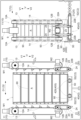
- the container processing facility 100 includes a loading unit 2 that receives the stacked container group 9 from the transport vehicle 60, an unloading unit 3 that delivers the stacked container group 9 to the transport vehicle 60, a work station 80, It includes a destacking device 1A, a stacking device 1B, a first transport device 41, and a second transport device .
- a work station 80 In the example shown in FIG. 1, only one work station 80 is arranged on the transport path of the container 90 or the stacked container group 9 between the loading section 2 and the unloading section 3.
- a plurality of work stations 80 may be arranged on the transport path of the container 90 or the stacked container group 9 between the unit 3 .
- the container processing facility 100 includes a control device 8, as shown in a simplified manner in FIG.
- Each function of the control device 8 is realized by cooperation between hardware such as an arithmetic processing unit and a program executed on the hardware.
- the control device 8 may be configured not by one piece of hardware but by a set of multiple pieces of hardware (a plurality of separate pieces of hardware) that can communicate with each other by wire or wirelessly.
- the control device 8 controls the operation of each part of the container processing facility 100 .
- a control unit equipment controller
- a driving force source for example, an electric motor
- the operation of each part of the container processing facility 100 controlled by the control device 8 includes the receiving operation of the stacked container group 9 from the transport vehicle 60 by the carry-in unit 2, delivery operation, destacking operation by the destacking device 1A (operation for performing destacking processing), stacking operation by the stacking device 1B (operation for performing stacking processing), container 90 or stacking container by the first conveying device 41
- the transport operation of the group 9 and the transport operation of the container 90 or the stacked container group 9 by the second transport device 42 are included.
- a work device 82 which will be described later
- the operation of each part of the container processing facility 100 controlled by the control device 8 includes the operation of the work device 82 for working on the container 90.
- an output device 84 which will be described later, is arranged in the work station 80, the operation of each part of the container processing facility 100 controlled by the control device 8 includes the operation of outputting a work instruction by the output device 84.
- the carry-in section 2 is arranged adjacent to the traveling route 6 of the carrier 60 .
- the direction along the running route 6 is the running direction R
- the direction perpendicular to both the running direction R and the vertical direction V is the route width direction W.
- the position of the transport vehicle 60 on the right side of the two transport vehicles 60 is the position corresponding to the carry-in section 2 on the travel route 6 .
- up, down, left, and right in the drawings mean up, down, left, and right when the reference numerals in the drawings are viewed in a readable direction.
- the loading section 2 receives the stacked container group 9 from the transporting vehicle 60 while the transporting vehicle 60 is stopped at a position corresponding to the loading section 2 on the traveling path 6 .
- the carry-in section 2 is provided with a conveyor (a belt conveyor C2 in the example shown in FIG. 1) that conveys the stacked container group 9 in the horizontal direction H.
- a conveyor a belt conveyor C2 in the example shown in FIG. 1
- the carry-in section 2 receives the stacked container group 9 from the transport vehicle 60
- the conveyor provided in the carry-in section 2 is operated and the conveyor provided at the support section 61 of the transport vehicle 60 is operated.
- the stacked container group 9 is moved from the transport vehicle 60 (specifically, the support section 61 ) to the carry-in section 2 .
- the unloading section 3 is arranged adjacent to the traveling route 6 of the transport vehicle 60 .
- the carry-out section 3 is arranged adjacent to the travel route 6 in the route width direction W.
- the section formed in a straight line as viewed in the vertical direction in the traveling route 6 is defined as a straight section, and in the example shown in FIG. are arranged to
- the position of the transport vehicle 60 on the left side of the two transport vehicles 60 is the position corresponding to the unloading section 3 on the travel route 6 .
- the carry-out section 3 delivers the stacked container group 9 to the carrier 60 while the carrier 60 is stopped at a position corresponding to the carry-out section 3 on the travel route 6 .
- the carry-out section 3 is provided with a conveyor (a belt conveyor C2 in the example shown in FIG. 1) that conveys the stacked container group 9 in the horizontal direction H. As shown in FIG.
- the carry-out section 3 delivers the stacked container group 9 to the carrier 60, the conveyor provided in the carry-out section 3 is operated and the conveyor provided at the support section 61 of the carrier 60 is operated. Then, the stacked container group 9 is moved from the unloading section 3 to the transport vehicle 60 (specifically, the support section 61).
- the carry-in section 2 and the carry-out section 3 are arranged on the same side in the route width direction W with respect to the travel route 6 .
- the loading section 2 and the unloading section 3 are arranged at the same position in the width direction W of the route with a space therebetween in the running direction R.
- the carrying-in section 2 and the carrying-out section 3 are arranged side by side with a space therebetween in the traveling direction R. As shown in FIG.
- the distance between the carrying-in section 2 and the carrying-out section 3 in the traveling direction R is the transport vehicle 60 (on the right side in FIG. The transport vehicle 60) and the transport vehicle 60 (left transport vehicle 60 in FIG. 1) receiving the stacked container group 9 from the unloading section 3 can be arranged side by side in the traveling direction R without interfering with each other. is set.
- the distance in the traveling direction R between the loading section 2 and the unloading section 3 is the transport vehicle 60 that is delivering the stacked container group 9 to the loading section 2 and the stacked container group 9 from the unloading section 3.
- At least one of the loading section 2 and the unloading section 3 is the target section 4 , and in the present embodiment, the target section 4 supplies electric power to the transport vehicle 60 stopped for delivery of the stacked container group 9 to and from the target section 4 .
- a power supply unit 5 for supplying
- both the loading section 2 and the unloading section 3 are the target section 4
- both the loading section 2 and the unloading section 3 are provided with the power feeding section 5 .
- only one of the loading section 2 and the unloading section 3 may be the target section 4
- only one of the loading section 2 and the unloading section 3 may be provided with the power supply section 5 . .
- the transport vehicle 60 includes a power receiving unit 63 electrically connected to a power storage device 64 .
- Electric power is supplied from the power supply unit 5 to the transport vehicle 60 while the power supply unit 5 and the power receiving unit 63 are electrically connected, and the power storage device 64 is charged with the electric power.
- the power supply unit 5 is arranged below the support surface of the stacked container group 9 in the target unit 4 (specifically, the conveying surface of the conveyor provided in the target unit 4) V2.
- the power receiving unit 63 is disposed on the lower side V2 than the support surface of the stacked container group 9 in the support unit 61 of the transport vehicle 60 (specifically, the conveying surface of the conveyor provided in the support unit 61).
- power is supplied from the power supply unit 5 to the transport vehicle 60 in a state in which the power supply coil provided in the power supply unit 5 and the power reception coil provided in the power reception unit 63 are electrically connected in a non-contact manner.
- a work device 82 or an output device 84 is arranged in the work station 80 .
- the work device 82 is a device that performs work on the container 90 .
- the output device 84 is a device that outputs work instructions to the worker 83 who works on the container 90 .
- a work subject 81 including at least one of a work device 82 and a worker 83 is arranged at the work station 80 .
- an output device 84 is arranged in the work station 80 .
- the output device 84 is, for example, a display (monitor) that displays work instructions on a screen.
- the output device 84 may be a monitor of a mobile terminal possessed by the worker 83, or if the worker 83 is wearing smart glasses (a display device integrated with glasses), a smart It can be glass.
- the work station 80 performs a picking operation of taking out the contents contained in the container 90 from the container 90 .
- the contents stored in the container 90 are taken out through the opening on the upper surface of the container 90 .
- the contents taken out of the container 90 are stored in, for example, a shipping container.
- the work device 82 is arranged in the work station 80
- the work device 82 is a picking device (picking robot) that picks up the container 90 .
- an output device 84 is arranged in the work station 80
- the work instruction output by the output device 84 includes the number of items to be taken out from the container 90 .
- the first transport device 41 transports the stacked container group 9 received from the transport vehicle 60 in the carry-in section 2 to the destacking device 1A, and the containers 90 sequentially separated from the stacked container group 9 in the destacking device 1A are processed. It is a device for transporting to station 80 .
- the first conveying device 41 conveys the container 90 or the stacked container group 9 along the horizontal plane. That is, in the present embodiment, the first transport direction T1, which is the transport direction of the first transport device 41, is the horizontal direction H. As shown in FIG. Here, as shown in FIG.
- the section between the carry-in section 2 and the deleveling device 1A in the first transport device 41 is defined as a first upstream section 41A
- the deleveling device 1A and the work in the first transport device 41 A section to the station 80 is defined as a first downstream section 41B.
- the step removing device 1A is not included in either the first upstream section 41A or the first downstream section 41B.
- a plurality of containers 90 are transported together in a stacked state, and in the first downstream section 41B, the containers 90 are transported one by one.
- the second conveying device 42 conveys the containers 90 from the work station 80 to the stacking device 1B, and conveys the stacked container group 9 generated by sequentially stacking the plurality of containers 90 in the stacking device 1B to the unloading section 3. It is a device.
- the second conveying device 42 conveys the container 90 or the stacked container group 9 along the horizontal plane. That is, in the present embodiment, the second conveying direction T2, which is the conveying direction of the second conveying device 42, is the horizontal direction H. As shown in FIG. Here, as shown in FIG.
- the section between the work station 80 and the stacking device 1B in the second conveying device 42 is defined as a second upstream section 42A, and the stacking device 1B in the second conveying device 42 and the unloading section 42A Let the section between the part 3 be the 2nd downstream section 42B. Note that the stacking device 1B is not included in either the second upstream section 42A or the second downstream section 42B.
- the containers 90 are conveyed one by one, and in the second downstream section 42B, the containers 90 are collectively conveyed in a stacked state.
- a specific horizontal direction H (here, a horizontal direction H parallel to the running direction R) is defined as a first horizontal direction H1
- a horizontal direction H orthogonal to the first horizontal direction H1 (here, a route A horizontal direction H) parallel to the width direction W is defined as a second horizontal direction H2.
- the first conveying device 41 and the second conveying device 42 are configured such that the conveying route of the container 90 or the stacked container group 9 between the loading unit 2 and the unloading unit 3 is vertically arranged. They are arranged in an angular U shape when viewed from the direction.
- a destacking device 1A is arranged at a portion corresponding to one side of the two opposing sides of the U shape, and a stacking device 1B is arranged at a portion corresponding to the other side.
- a work station 80 is arranged at a portion corresponding to the bottom of the U shape.
- the destacking device 1A and the stacking device 1B are arranged at the same position in the second horizontal direction H2.
- the first upstream section 41A is arranged to convey the stacked container group 9 to the side away from the travel route 6 along the second horizontal direction H2.
- the first downstream section 41B conveys the container 90 along the second horizontal direction H2 to the side away from the travel path 6, and then conveys the container 90 along the first horizontal direction H1 toward the work station 80 side.
- the second upstream section 42A transports the container 90 away from the work station 80 along the first horizontal direction H1, and then transports the container 90 toward the travel path 6 along the second horizontal direction H2.
- the second downstream section 42B is arranged to transport the containers 90 (specifically, the stacked container group 9) to the side closer to the travel route 6 along the second horizontal direction H2.
- the first conveying device 41 and the second conveying device 42 are configured using a roller conveyor C1, a belt conveyor C2, and a direction changing conveyor C3.
- the roller conveyor C1 includes a plurality of rollers 51 that are driven to rotate.
- a plane (virtual plane) that includes the upper ends of the plurality of rollers 51 is the conveying plane of the roller conveyor C1.
- the belt conveyor C2 has a belt 52 that is driven to rotate (circulate). The upper surface of the belt 52 serves as the conveying surface of the belt conveyor C2.
- the belt conveyor C2 is a belt conveyor provided with two (a pair of) belts 52 arranged separately on both sides in the conveying width direction (a direction orthogonal to the conveying direction when viewed in the vertical direction) (two belt conveyor ).
- the direction change conveyor C3 is a conveyor that can change the conveying direction to a right angle when viewed in the vertical direction.
- the direction-changing conveyor C3 includes a first transport section that transports the container 90 in the first horizontal direction H1 and a second transport section that transports the container 90 in the second horizontal direction H2. .
- the direction changing conveyor C3 conveys the container 90 in the first horizontal direction H1 by raising the first conveying portion to the conveying surface and lowering the second conveying portion below the conveying surface, and moving the second conveying portion to the first horizontal direction H1. It is configured to transport the container 90 in the second horizontal direction H2 by raising it to the transport surface and lowering the first transport unit below the transport surface.
- the first upstream section 41A is configured so that a plurality of stacked container groups 9 can be arranged side by side along the transport direction (that is, the first transport direction T1).
- the first upstream section 41A includes three belt conveyors C2 arranged along the conveying direction, and the three stacked container groups 9 are divided into these three belt conveyors C2. It is configured so that it can be placed. That is, the first upstream section 41A is configured so that three stacked container groups 9 can be arranged side by side along the transport direction.
- the conveyor arranged on the most upstream side in the first conveying direction T ⁇ b>1 is provided in the carry-in section 2 .
- these three belt conveyors C2 are configured to be able to carry out the conveying operation independently of each other.
- the three belt conveyors C2 provided in the first upstream section 41A perform the conveying operation independently of the roller conveyor C1 provided at the de-tiering target position P (see FIG. 1) described later. configured to be able to do so.
- the first upstream section 41A is configured to be able to transport and stop the stacked container group 9 without affecting the destacking process by the destacking device 1A. .
- the first downstream section 41B includes a roller conveyor C1, a turning conveyor C3, and a roller conveyor C1 in order from the upstream side along the transport direction (that is, the first transport direction T1). It has And these three conveyors with which the 1st downstream section 41B is provided are comprised so that conveyance operation can be performed independently of the roller conveyor C1 provided in the deleveling object position P. As shown in FIG. Thus, in the present embodiment, the first downstream section 41B is configured so that the containers 90 can be transported and stopped without affecting the destacking process by the destacking device 1A. Of the three conveyors, the conveyor arranged on the most downstream side in the first transport direction T1 is provided in the work station 80. As shown in FIG.
- the second downstream section 42B is configured so that a plurality of stacked container groups 9 can be arranged side by side along the transport direction (that is, the second transport direction T2).
- the second downstream section 42B includes three belt conveyors C2 arranged along the conveying direction, and the three stacked container groups 9 are divided into these three belt conveyors C2. It is configured so that it can be placed. That is, the second downstream section 42B is configured so that three stacked container groups 9 can be arranged side by side along the transport direction.
- the conveyor arranged on the most downstream side in the second conveying direction T ⁇ b>2 is provided in the unloading section 3 .
- these three belt conveyors C2 are configured to be able to carry out the conveying operation independently of each other.
- the three belt conveyors C2 provided in the second downstream section 42B perform the conveying operation independently of the belt conveyor C2 provided at the stacking target position Q (see FIG. 1) described later. configured to be able to do so.
- the second downstream section 42B is configured to be able to transport and stop the stacked container group 9 without affecting the stacking process by the stacking device 1B. .
- the second upstream section 42A includes two roller conveyors C1, a direction changing conveyor C3, and roller It has a conveyor C1.
- These four conveyors provided in the second upstream section 42A are configured to be able to carry out a conveying operation independently of the belt conveyor C2 provided at the stacking target position Q.
- the second upstream section 42A is configured so that the container 90 can be transported and stopped without affecting the stacking process by the stacking device 1B.
- the conveyor arranged on the most upstream side in the second conveying direction T2 is provided in the work station 80. As shown in FIG.
- the conveyor provided in the first downstream section 41B and arranged in the work station 80 and the conveyor provided in the second upstream section 42A and arranged in the work station 80 are common.
- a conveyor in this example, a roller conveyor C1 is used.
- the first transport device 41 and the second transport device 42 are at least conceptually distinguished, and as in the example shown in FIG. 1, the first transport device 41 and the second transport device 42 are common devices. (Here, the roller conveyor C1) may be used.
- the weight of the container 90 being transported by the second transport device 42 is measured between the work station 80 and the stacking device 1B on the transport path of the second transport device 42.
- a weighing unit 7 is provided for weighing.
- a work station 80 is also included between the work station 80 and the stacking device 1B on the transport path of the second transport device 42 .
- the weighing section 7 is provided with a weighing device 53 for measuring the weight of the container 90 placed on the conveying surface 42S of the second conveying device 42 .
- the weighing unit 7 is provided downstream of the work station 80 in the second transport direction T2. Specifically, the weighing unit 7 is provided on the roller conveyor C1 provided adjacent to the roller conveyor C1 provided in the work station 80 on the downstream side in the second conveying direction T2.
- the control device 8 determines that the weight of the container 90 measured by the weighing unit 7 is the weight obtained by subtracting the total weight of the contents to be taken out from the container 90 from the weight of the container 90 before the picking operation is performed. If the weight corresponds to a certain criterion weight, it is determined that the work at the work station 80 has been properly performed.
- control device 8 allows the work at the work station 80 to be completed when the weight of the container 90 measured by the weighing unit 7 corresponds to the above-mentioned criterion weight. Determined as complete.
- the destacking device 1A is a device that performs destacking processing for sequentially separating the containers 90 from the stacked container group 9 .
- the destacking device 1A performs destacking processing on the stacked container group 9 arranged at the destacking target position P (see FIG. 1) on the transport path of the first transport device 41 .
- the stacking device 1B is a device that performs a stacking process of sequentially stacking a plurality of containers 90 to form a stacked container group 9 .
- the stacking device 1B stacks the containers 90 arranged at the stacking position Q (see FIG. 1) on the transport path of the second transport device 42 .
- a portion including at least the de-tiering target position P in the first conveying device 41 is configured using a roller conveyor C1.
- the stacked container group 9 can be transported at the target position P for de-leveling. It is easy to move in the conveying width direction (the direction perpendicular to the first conveying direction T1 when viewed in the vertical direction). Therefore, for example, when aligning the transport width direction of the stacked container group 9 carried into the de-leveling target position P before the de-leveling process by the de-leveling device 1A, the transport width of the stacked container group 9 Easy to adjust the direction position.
- the roller conveyor C1 is also provided in part of the first downstream section 41B. Therefore, in the example shown in FIG. 1, a portion including the de-tiering target position P and part of the first downstream section 41B in the first conveying device 41 are configured using the roller conveyor C1.
- a portion including at least the stacking target position Q in the second conveying device 42 is configured using a belt conveyor C2.
- the stacking container group 9 at the stacking target position Q and the It is easy to suppress slippage between the second conveying device 42 and the second conveying device 42 . Therefore, even when the weight of the stacked container group 9 generated by the stacking device 1B is heavy, the slippage between the stacked container group 9 and the second conveying device 42 is suppressed to a small extent, and the object stacking position is maintained. From Q, the stacked container group 9 can be carried out appropriately.
- the belt conveyor C2 is also provided throughout the second downstream section 42B. Therefore, in the example shown in FIG. 1, the portion including the stacking target position Q and the entire second downstream section 42B in the second conveying device 42 are configured using the belt conveyor C2.
- the second conveying position is positioned at a position corresponding to the downstream edge of the stacking target position Q (the downstream edge in the second conveying direction T2) in the second conveying direction T2.
- a stopper 50 is arranged to extend and retract with respect to the conveying surface 42S of the device 42 .
- the portion including the stacking target position Q in the second conveying device 42 is configured using the belt conveyor C2. Therefore, the upper surface of the belt 52 of the belt conveyor C2 serves as the conveying surface 42S of the second conveying device 42 at the stacking target position Q (see FIG. 12). As shown in FIG.
- the containers 90 conveyed by the second conveying device 42 can be properly stacked at the stacking position Q (see FIG. 1). can be stopped. Further, as shown in FIG. 20, by retracting the stopper 50 to the lower side V2 so as not to protrude to the upper side V1 with respect to the conveying surface 42S, the stacked container group 9 is moved to the stacking target position Q (see FIG. 1). can be suitably unloaded by the second transport device 42 from the .
- the belt conveyor C ⁇ b>2 that constitutes the portion including the stacking target position Q in the second conveying device 42 is a double belt conveyor provided with a pair of belts 52 .
- the stopper 50 is arranged between the pair of belts 52 when viewed in the vertical direction. 12 to 20 to be referred to later, the stopper 50 is positioned in the second conveying direction T2 with respect to the belt conveyor C2, which constitutes the portion including the stacking target position Q in the second conveying device 42. It can also be configured to be arranged adjacently on the downstream side.
- the destacking device 1A and the stacking device 1B have a common configuration. That is, in this embodiment, one container processing apparatus 1 is used as the destacking apparatus 1A, and another container processing apparatus 1 having the same configuration as the container processing apparatus 1 is used as the stacking apparatus 1B. .
- the container processing device 1 when describing a configuration common to the destacking device 1A and the stacking device 1B, they will be described as the container processing device 1 without distinguishing between them.
- the container processing apparatus 1 performs a stacking process of sequentially stacking a plurality of containers 90 to form a stacked container group 9, and a stacking process of sequentially separating the containers 90 from the stacked container group 9 formed by stacking the plurality of containers 90.
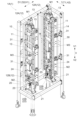
- the container processing apparatus 1 includes a conveying device 40, a first lifting device 10, and a second lifting device 20.
- the conveying device 40 is omitted.
- the container processing apparatus 1 further includes a support 30 that supports the conveying device 40 , the first lifting device 10 and the second lifting device 20 .
- the support 30 is formed by connecting frame members.
- the transport device 40 is a device that transports the container 90 placed on the placement surface 40S along the transport direction T intersecting the vertical direction V.
- a container group arrangement area A which is an arrangement area for the stacked container group 9, is set on the upper side V1 of the mounting surface 40S.
- the transport operation of the transport device 40 is controlled by a controller (not shown) provided in the container processing apparatus 1 .
- the container processing apparatus 1 shown in FIGS. 2 to 4 is a container processing apparatus 1 used as a destacking device 1A. Therefore, a portion of the first transport device 41 including the de-leveling target position P (see FIG. 1) constitutes a transport device 40 provided in the de-leveling device 1A.
- the transport direction T of the container 90 by the transport device 40 coincides with the first transport direction T1.
- the roller conveyor C1 which constitutes the portion including the de-leveling target position P in the first transporting device 41, constitutes the transporting device 40 provided in the de-leveling device 1A, and the conveying surface of the roller conveyor C1 is , and a mounting surface 40S of the conveying device 40 (see FIGS. 5 and 6).
- the portion including the stacking target position Q (see FIG. 1) in the second conveying device 42 is the stacking device 1B. constitutes a transport device 40 provided with.
- the transport direction T of the container 90 by the transport device 40 coincides with the second transport direction T2.
- the belt conveyor C2 which constitutes the portion including the stacking target position Q in the second conveying device 42, constitutes the conveying device 40 provided in the stacking device 1B. serves as the mounting surface 40S of the conveying device 40.
- the first lifting device 10 is a device that holds and lifts the stacked container group 9 . That is, the first lifting device 10 can collectively hold and lift a plurality of stacked containers 90 .
- the first lifting device 10 is arranged to hold and lift the container 90 on the upper side V1 of the mounting surface 40S.
- the first lifting device 10 includes a pair of first locking units 11 arranged to face each other across the container group arrangement region A, and a pair of first locking units 11 and a first drive unit M1 (an electric motor in this embodiment) that drives the .
- the driving of the pair of first locking units 11 by the first driving unit M1 is controlled by a controller (not shown) provided in the container processing apparatus 1. As shown in FIG.
- the first drive unit M1 is separately provided in each of the pair of first locking units 11, and the pair of first drive units M1 operates the pair of first drive units M1.
- the first locking unit 11 is driven. There is no difference in the driving mode of the first locking units 11 between the pair of first driving units M1, and the driving mode of the pair of first locking units 11 by the pair of first driving units M1 is It is the same as the case where the common first drive unit M1 for driving the first locking units 11 is provided. Therefore, in the following description, the pair of first drive units M1 is regarded as one first drive unit M1.
- the second lifting device 20 is a device that holds and lifts the lowest container 90 of the stacked container group 9 . That is, the second lifting device 20 can hold and lift one container 90 (specifically, the lowest container 90 of the stacked container group 9).
- the second lifting device 20 is arranged to hold and lift the container 90 on the upper side V1 of the placement surface 40S.
- the second lifting device 20 includes a pair of second locking units 21 arranged to face each other across the container group disposition area A, and a pair of second locking units 21 and a second drive unit M2 (an electric motor in this embodiment) that drives the .
- the driving of the pair of second locking units 21 by the second driving unit M2 is controlled by a controller (not shown) provided in the container processing apparatus 1. As shown in FIG.
- the second drive unit M2 is separately provided in each of the pair of second locking units 21, and the pair of second drive units M2 causes the pair of The second locking unit 21 is driven.
- the driving mode of the second locking units 21 between the pair of second driving units M2 is It is the same as the case where the common second drive unit M2 for driving the second locking unit 21 is provided. Therefore, in the following description, the pair of second drive units M2 is regarded as one second drive unit M2.
- the direction in which the pair of first locking units 11 face each other is defined as a first facing direction D1
- the direction in which the pair of second locking units 21 face each other is defined as a second facing direction. D2.
- the first opposing direction D1 and the second opposing direction D2 are arranged in parallel (parallel or substantially parallel).
- the transport direction T is a direction perpendicular to the first facing direction D1 when viewed from the top and bottom (see FIG. 4).
- the first facing direction D1 and the second facing direction D2 are along the first horizontal direction H1
- the conveying direction T is along the second horizontal direction H2.
- the first lifting device 10 operates to move the pair of first locking units 11 toward and away from each other along the first facing direction D1. It further comprises a 3-drive unit M3 (an electric motor in this embodiment). The movement of the pair of first locking units 11 toward and away from each other by the third drive unit M3 is controlled by a controller (not shown) provided in the container processing apparatus 1. As shown in FIG.
- the third drive unit M3 is separately provided in each of the pair of first locking units 11, and the pair of third drive units M3 causes the pair of By moving both of the first locking units 11 in the first opposing direction D1, the pair of first locking units 11 are moved closer to each other and away from each other along the first opposing direction D1. Note that there is no difference in the driving mode for moving the first locking unit 11 in the first opposing direction D1 between the pair of third driving units M3, and the pair of first locking units driven by the pair of third driving units M3 does not differ. 11 is the same as the case where the common third drive unit M3 for moving the pair of first locking units 11 toward and away from each other is provided. Therefore, in the following description, the pair of third drive units M3 is regarded as one third drive unit M3.
- the third drive unit M3 is configured to move the pair of first locking units 11 upward V1 while bringing the pair of first locking units 11 closer to each other along the first facing direction D1. It is Specifically, as shown in FIGS. 2 to 4, each of the pair of first locking units 11 is connected to the support 30 via a connecting mechanism 31 (here, a link mechanism). The 3-drive unit M3 causes the pair of first locking units 11 to approach and separate from each other along the first facing direction D1 via the connecting mechanism 31 .
- a connecting mechanism 31 here, a link mechanism
- the connecting mechanism 31 as the pair of first locking units 11 approach each other along the first facing direction D1, the pair of first locking units 11 move upward V1, and the pair of first locking units 11 Each of the pair of first locking units 11 is supported so that the pair of first locking units 11 move downward V2 as the locking units 11 move away from each other along the first opposing direction D1. It is connected to body 30 .
- the first locking unit 11 includes a first endless member 13 spanned between a pair of first rotors 12 spaced apart in the vertical direction V, and a first A plurality of first locking portions 14 are fixed to the outer peripheral portion of the first endless member 13 at regular intervals along the extending direction of the endless member 13 .
- a toothed pulley can be used as the first rotor 12 and a toothed belt can be used as the first endless member 13 .
- each of the pair of first locking units 11 includes a pair of first rotating bodies 12 and a first endless member 13 spanned therebetween. Equipped with two one-rotation units. These two first rotation units are configured such that the respective first endless members 13 rotate (circulate) in synchronization with each other. In this embodiment, these two first rotating units are spaced apart in the transport direction T. As shown in FIG.
- the first drive unit M1 is configured to synchronously rotate (circulate) the pair of first endless members 13 associated with the pair of first locking units 11 . That is, the first drive unit M1 includes a first endless member 13 provided in one of the pair of first locking units 11 (in this embodiment, the first endless members 13 of each of the two first rotation units). , and the first endless member 13 provided by the other of the pair of first locking units 11 (in this embodiment, the first endless members 13 of each of the two first rotating units) are synchronously driven to rotate. do.
- the first drive unit M1 is configured to rotationally drive the upper first rotor 12A. That is, in this embodiment, the upper first rotating body 12A is a driving rotating body, and the lower first rotating body 12B is a driven rotating body.
- each of the pair of first locking units 11 has a plurality of first locking portions 14 arranged in the vertical direction V facing the container group arrangement region A, and each of the first locking units 11 5 and 6) of each of the plurality of containers 90 constituting the stacked container group 9 arranged in the container group arrangement area A. placed in As a result, the plurality of containers 90 forming the stacked container group 9 can be collectively held and lifted by the first lifting device 10 .
- the container 90 includes the first locking portion 14 fixed to the first endless member 13 included in one first locking unit 11 of the pair of first locking units 11 and the other first locking portion 14 .
- the first locking portion 14 descends as the first endless member 13 rotates (in the container group arrangement region A). lowering), the lowermost container 90 is locked to the side surface S (locked by the first locking portion 14) before the lowermost container 90 is placed on the mounting surface 40S. is set to be released.
- the second locking unit 21 includes a second endless member 23 that spans a pair of second rotors 22 spaced apart in the vertical direction V, and a second and a second locking portion 24 fixed to the outer peripheral portion of the endless member 23 .
- a plurality of (specifically, two) second locking portions 24 are fixed. are fixed to the outer peripheral portion of the second endless member 23 at regular intervals along the extending direction of the second endless member 23 .
- a toothed pulley can be used as the second rotor 22 and a toothed belt can be used as the second endless member 23 .
- each of the pair of second locking units 21 includes a pair of second rotating bodies 22 and a second endless member 23 that spans them. It has two 2-rotation units. These two second rotation units are configured such that the respective second endless members 23 rotate (circulate) in synchronization with each other. In this embodiment, these two second rotating units are spaced apart in the transport direction T. As shown in FIG.
- the second drive unit M2 is configured to synchronously rotate (circulate) the pair of second endless members 23 associated with the pair of second locking units 21 . That is, the second drive unit M2 includes the second endless member 23 provided in one of the pair of second locking units 21 (in this embodiment, the second endless members 23 of each of the two second rotation units). , and the second endless member 23 provided by the other of the pair of second locking units 21 (in this embodiment, the second endless members 23 of the two second rotating units) are synchronously driven to rotate. do.
- the one arranged on the upper side V1 is referred to as an upper second rotating body 22A
- the one arranged on the lower side V2 is the lower side. It is referred to as a second rotating body 22B.
- the second drive unit M2 is configured to rotationally drive the upper second rotor 22A. That is, in this embodiment, the upper second rotating body 22A is a driving rotating body, and the lower second rotating body 22B is a driven rotating body.
- the lower second rotating body 22B is arranged lower V2 than the lower first rotating body 12B.
- the fact that the lower second rotating body 22B is disposed on the lower side V2 than the lower first rotating body 12B means that at least the lowest part of the lower second rotating body 22B 12B is arranged on the lower side V2 than the lowest part of 12B.
- the entire lower second rotating body 22B is arranged on the lower side V2 than the lowermost portion of the lower first rotating body 12B.
- each of the pair of second locking units 21 is arranged in the container group arrangement area A with the second locking portions 24 facing the container group arrangement area A. 5 and 6) of the lowermost container 90 of the stacked container group 9.
- the container 90 includes the second locking portion 24 fixed to the second endless member 23 included in one of the pair of second locking units 21 and the other second locking portion 24 . It is held from both sides in the second facing direction D2 by the second locking portion 24 fixed to the second endless member 23 provided in the locking unit 21 .
- the second locking portion 24 descends as the second endless member 23 rotates (in the container group arrangement region A). ), at the same time when the lowest container 90 is placed on the placement surface 40S, the lowermost container 90 is locked to the side surface S (locked by the second locking portion 24). ) is released.
- “simultaneous period” does not necessarily have to be strictly simultaneous, but means a period with a certain width (for example, a width that can be said to be simultaneous).
- the plurality of containers 90 forming the stacked container group 9 can be collectively held and lifted by the first elevating device 10, and the second elevating device 20 enables the stacking of the containers. Only the lowest container 90 of the stacked container group 9 can be held and lifted.
- the first drive unit M1 and the second drive unit M2 are configured to operate independently of each other. Therefore, the pair of first locking units 11 of the first lifting device 10 and the pair of second locking units 21 of the second lifting device 20 can be operated independently of each other. As a result, the second lifting device 20 can smoothly move the lowermost container 90 between the stacked container group 9 and the transport device 40 in the de-tiering process and the stacking process, which will be described later. It has become.
- the side surface S of the container 90 has a first locked portion 91 to which the first locking portion 14 is locked and a second locked portion to which the second locking portion 24 is locked.
- 2 to-be-engaged portions 92 are formed.
- a protrusion (rib) projecting outward from the side surface S is formed on the side surface S of the container 90 so as to extend in the horizontal direction H.
- a second locked portion 92 is formed.
- the protrusions formed on the side surface S of the container 90 are used as the first engaged portion 91 and the second engaged portion 92 .
- the first locking portion 14 is engaged with the lower surface of the first locked portion 91, as indicated by the two-dot chain line in FIG. be stopped. Similarly, as shown by the two-dot chain line in FIG. Locked to the bottom surface.
- the first locking unit 11 is fixed to the first endless member 13 of one of the two first rotating units of the first locking unit 11 .
- the stop portion 14 and the first locking portion 14 fixed to the first endless member 13 of the other first rotation unit are arranged to move the container 90 at different positions in the horizontal direction H (here, the second horizontal direction H2). is locked to the side surface S of the
- the second locking portion 24 fixed to the second endless member 23 of one of the two second rotating units included in the second locking unit 21 and the , and the second engaging portion 24 fixed to the second endless member 23 of the other second rotating unit are positioned on the side surface S of the container 90 at different positions in the horizontal direction H (here, the second horizontal direction H2). Locked.
- the side surface S of the container 90 to which the first locking portion 14 is locked is referred to as a first target side surface S1
- the side surface S of the container 90 to which the second locking portion 24 is locked is referred to as a second target side surface S2.
- two side surfaces S facing both sides in the first opposing direction D1 are the first target side surfaces S1.
- Two side surfaces S of the four side surfaces S of the container 90 facing both sides in the second facing direction D2 are the second target side surfaces S2.
- the first facing direction D1 and the second facing direction D2 are arranged in parallel. Therefore, as shown in FIG. 6, the side surface S is common to the first target side surface S1 and the second target side surface S2.
- two first cover surfaces in the horizontal direction H (here, the second horizontal direction H2)
- Two second locked portions 92 are arranged between the locking portions 91 .
- the second locked portion 92 is arranged at a different position in the horizontal direction H (here, the second horizontal direction H2) from the first locked portion 91 .
- the second locked portion 92 is arranged below the first locked portion 91 V2.
- the first rotation axis X1 which is the rotation axis of the first rotor 12, is arranged along the second horizontal direction H2.
- the first target side surface S1 and the second target side surface S2 are surfaces orthogonal to the first horizontal direction H1. Therefore, in the present embodiment, the rotation axes (first rotation axes X1) of the pair of first rotating bodies 12 are arranged along the horizontal direction H and parallel to the first target side surface S1.
- the rotation axes (second rotation axes X2) of the pair of second rotors 22 are arranged along the horizontal direction H and parallel to the second target side surface S2. there is Accordingly, by rotating the second endless member 23 , it is possible to engage and disengage the second engaging portion 24 with the second engaged portion 92 .
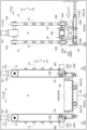
- FIG. A control unit provided in the destacking device 1A controls the driving of the first driving unit M1, the second driving unit M2, the third driving unit M3, etc. so as to perform each operation described below, thereby destacking Processing is performed.
- 7 to 11 chronologically show scenes in which the step breaking process is executed, and as the figure number increases, the situation at a later point in time is shown.
- 7 to 11 show a front view and a side view of the container processing apparatus 1 (destacking apparatus 1A) side by side for easy understanding.
- the stacked container group 9 to be destacked is carried into the destacking target position P (see FIG. 1) by the transport operation of the transport device 40 (first transport device 41).
- the stacked container group 9 transported to the de-tiering target position P is arranged in the container group arrangement area A.
- the pair of first locking units 11 is arranged so that the first locking unit 11 and the stacked container group 9 do not interfere with each other. in the first facing direction D1 is widened to such an interval that the first locking portion 14 fixed to the first endless member 13 does not interfere with the stacked container group 9 .
- the second endless member 23 is arranged so that the second locking unit 21 and the stacked container group 9 do not interfere with each other. is set to a position where the second locking portion 24 does not interfere with the stacked container group 9 .
- the second lifting device 20 includes a fourth drive unit (for example, an electric motor) that moves the pair of second locking units 21 toward and away from each other along the second facing direction D2.
- a fourth drive unit for example, an electric motor
- the distance between the pair of second locking units 21 in the second facing direction D2 should be widened to such an interval that the second locking portions 24 fixed to the second endless members 23 do not interfere with the stacked container group 9 .
- interference between the second locking unit 21 and the stacked container group 9 may be avoided.
- the first locking portion 14 fixed to the first endless member 13 is the first locked portion when viewed from the top and bottom, and the first locking portion 14 fixed to the first endless member 13 separates the pair of first locking units 11 from each other in the first facing direction D1. 91 (see FIG. 6), the pair of first endless members 13 related to the pair of first locking units 11 are moved in the direction in which the first locking portions 14 rise in the container group arrangement region A.
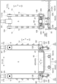
- a plurality of first locking portions 14 are fixed to the outer peripheral portion of the first endless member 13 at regular intervals along the extending direction of the first endless member 13. It corresponds to the space in the vertical direction V between the first engaged portion 91 of one of two containers 90 adjacent to each other in the vertical direction V and the first engaged portion 91 of the other. Therefore, as shown in FIG. 8, the first locking portions 14 are locked to the side surfaces S of the containers 90 other than the container 90 in the lowest stage.
- the pair of first endless members 13 associated with the pair of first locking units 11 are arranged so that the container 90 on the second stage from the bottom
- the lowermost container 90 is disengaged from the container 90 and is rotated until it reaches a height (hereinafter referred to as "unloadable height") at which the lowermost container 90 can be unloaded in the transport direction T (first transport direction T1).
- the lowest container 90 is carried out in the transport direction T (see the right side of FIG. 8).
- the pair of first locking units 11 moves upward V1, but the pair of first locking units 11 moves to the upper side V1.
- the first engaging portion 14 does not engage with the first engaged portion 91 of the container 90 by narrowing the space between the units 11 in the first facing direction D1.
- the first locking portion 14 is locked to the first locked portion 91 of the container 90 by narrowing the distance between the pair of first locking units 11 in the first facing direction D1.
- the container 90 on the second stage from the bottom can be lifted to the above-described unloadable height.
- the lowermost container 90 can be carried out without rotating the pair of first endless members 13 associated with the first locking unit 11 .
- the new lowermost container 90 (the second container 90 from the bottom at the time of being carried in to the de-tiering target position P) is removed.
- the pair of second endless members 23 related to the pair of second locking units 21 are arranged so that the second locking portions 24 are arranged at positions where they can be locked to the locked portions 92 (see FIG. 6). rotate.
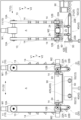
- the pair of first endless members 13 associated with the pair of first locking units 11 is rotated in the direction in which the first locking portion 14 descends in the container group arrangement area A, and the new lowermost container 90 ( Hereinafter, simply referred to as the lowermost container 90) is the height at which the second locking portion 24 is locked to the second locked portion 92 of the container 90 (the same height as the container 90 in FIG. 14). ).
- the second locking portion 24 is locked to the second locked portion 92 of the lowermost container 90 where the first locking portion 14 is locked to the first locked portion 91 .
- the pair of first endless members 13 associated with the pair of first locking units 11 is rotated in the direction in which the first locking portions 14 descend in the container group arrangement region A, and the second locking portions 24 are moved to the containers.
- the pair of second endless members 23 associated with the pair of second locking units 21 is rotated in the downward direction in the group arrangement area A, the first cover of the first locking portion 14 is moved as shown in FIG.
- the lowermost container 90 which has been released from the engagement with the engagement portion 91, can be lowered while being held by the second elevating device 20 and placed on the mounting surface 40S.
- the vertical position of the lower V2 is lower than the lower limit position where the container 90 can be held by the first lifting device 10.
- container 90 can be raised and lowered by second lifting device 20 . Therefore, even after the locking of the first locking portion 14 to the first locked portion 91 is released, the lowermost container 90 can be lowered while being held by the second lifting device 20 .
- the state in which the second engaging portion 24 is engaged with the second engaged portion 92 is maintained until the lowermost container 90 is lowered onto the mounting surface 40S, and the lowermost container 90 is lowered. As the weight of 90 is supported by the mounting surface 40S, the locking of the second locking portion 24 to the second locked portion 92 is released.
- the first locking unit 11 when the first locking portion 14 descends as the first endless member 13 rotates, the lowest container 90 is placed on the placement surface 40S. It is provided so that locking (locking of the first locking portion 14) to the side surface S of the lowermost container 90 is released before the lowermost container 90.
- the second locking unit 21 when the second locking portion 24 descends with the rotation of the second endless member 23, the second locking unit 21 is arranged such that the lowest container 90 is mounted on the mounting surface 40S. At the same time, the locking (locking of the second locking portion 24) to the side surface S of the lowermost container 90 is released. In this manner, before the lowermost container 90 is placed on the placing surface 40S, the first locking portion 14 is released from the side surface S of the lowermost container 90. It is possible to separate the lowermost container 90 from the group of other containers 90 held by the first lifting device 10 to the lower side V2 and lower it onto the placement surface 40S.
- the pair of second engaging portions 24 are kept in a fixed position until the second engaging portion 24 is disposed at a position where it does not interfere with the lowermost container 90, as shown in FIG.
- the lowest container 90 can be carried out (see the right side of FIG. 11).
- the lowest container 90 can be sequentially separated and carried out.
- FIG. A control unit provided in the stacking device 1B controls the driving of the first driving unit M1, the second driving unit M2, the third driving unit M3, etc. so as to perform each operation described below, thereby stacking Processing is performed.
- 12 to 20 show scenes in which the stacking process is executed in chronological order. 12 to 20, a front view and a side view of the container processing apparatus 1 (stacking apparatus 1B) are shown side by side for easy understanding.
- the container 90 to be stacked is carried into the stacking target position Q (see FIG. 1) by the transport operation of the transport device 40 (second transport device 42).
- the rotation position of the first endless member 13 is adjusted so that the first locking portion 14 does not interfere with the containers 90 so that the first locking unit 11 and the containers 90 do not interfere with each other.
- the rotation position of the second endless member 23 is set to a position where the second locking portion 24 does not interfere with the container 90 so that the second locking unit 21 and the container 90 do not interfere with each other.
- the stopper 50 is caused to protrude upward V1 with respect to the placement surface 40S (conveyance surface 42S).
- the pair of second locking units 21 are driven so that the container 90 placed on the placement surface 40S is lifted by the second lifting device 20.
- the mounting surface 40S is rotated.
- the second lifting device 20 holds and lifts the container 90 placed on the .
- the container 90 is held by the second lifting device 20 with the second locking portion 24 locked to the second locked portion 92 of the container 90 .
- the pair of second endless members 23 associated with the pair of second locking units 21 is set at a height at which the container 90 can be held by the first lifting device 10 (in other words, the first cover of the container 90). It is rotated until it rises to a height at which the locking portion 91 can lock the first locking portion 14 .
- the first locking portion 14 is positioned in the container group arrangement area A.
- the container 90 can be held by the first lifting device 10 by causing the first engaging portion 14 to engage with the first engaged portion 91 of the container 90 that is engaged with the container 90 .
- the pair of first locking units is held.
- the pair of first endless members 13 associated with 11 are rotated, and the pair of second engaging units 21 associated with the pair of second engaging units 21 are rotated until the second engaging portion 24 is positioned so as not to interfere with the new container 90 .
- the second endless member 23 is rotated.
- a new container 90 to be stacked is carried in. Note that the new container 90 to be stacked is added as the lowest container 90 to the container 90 held by the first lifting device 10 or to the stacked container group 9.
- the new container 90 is called the lowermost container 90 .
- the pair of second endless members 23 associated with the pair of second locking units 21 are rotated in the direction in which the second locking portion 24 rises in the container group arrangement area A, thereby
- the lowermost container 90 placed on 40S is raised to a height where the bottom of the container 90 held by the first lifting device 10 fits into the upper opening of the lowermost container 90 .
- the pair of first endless members 13 associated with the pair of first locking units 11 is rotated in the direction in which the first locking portions 14 rise in the container group arrangement region A, and the second locking portions 24 move toward the containers.
- the first engaging portion 14 is engaged with the first engaged portion 91 of the lowest container 90 that is engaged with the engaging portion 92 , and the lowest container 90 is lifted by the first lifting device 10 . can hold. After that, although not shown in the drawings, the stacking container group 9 held by the first lifting device 10 is raised to a height at which a new container 90 to be stacked can be carried in, and the pair of first latches are lifted. While rotating the pair of first endless members 13 associated with the stop unit 11 , the pair of second engaging units 21 are rotated until the second engaging portion 24 is positioned so as not to interfere with the new container 90 . The pair of second endless members 23 are rotated.
- the containers 90 to be stacked can be sequentially added as the lowest container 90 to the stacked container group 9 held by the first lifting device 10 . Then, as shown in FIG. 18, when the last container 90 to be stacked is carried in, the stacking process is completed as follows.
- the first locking portion 14 engages the pair of first locking units 11 in the descending direction in the container group arrangement area A until the bottom of the lower container 90 fits into the upper opening of the last container 90 .
- the pair of first endless members 13 are rotated, and then the first locking portions 14 fixed to the first endless members 13 are stepped to separate the pair of first locking units 11 in the first facing direction D1.
- the space is widened so as not to interfere with the stacking container group 9. ⁇ Then, as shown in FIG.
- the conveying device 40 (second conveying device 42) is moved.
- the stacked container group 9 generated by the stacking process is carried out from the stacking target position Q (see FIG. 1).
- the first lifting device 10 includes the third driving unit M3 that moves the pair of first locking units 11 toward and away from each other along the first opposing direction D1. , the third driving unit M3 moves the pair of first locking units 11 to the upper side V1 while bringing the pair of first locking units 11 closer to each other along the first opposing direction D1.
- the present disclosure is not limited to such a configuration, and the third drive unit M3 moves the pair of first locking units 11 along the first opposing direction D1 while maintaining their positions in the vertical direction V. It is also possible to adopt a configuration in which they approach and separate from each other.
- the stacking container group 9 can be carried in between the pair of first locking units 11, or the pair of first locking units 11 can be moved. If the stacked container group 9 can be properly carried out from between the stopping units 11, the first lifting device 10 can be configured without the third drive unit M3.
- the first facing direction D1 and the second facing direction D2 are arranged in parallel, and the transport direction T is a direction perpendicular to the first facing direction D1 when viewed from above.
- the first facing direction D1 and the conveying direction T may be arranged in parallel, and the conveying direction T may be a direction perpendicular to the second facing direction D2 when viewed from above.
- the second facing direction D2 and the conveying direction T are parallel to each other.
- the conveying direction T is a direction orthogonal to the first facing direction D1 when viewed from above.
- the first opposing direction D1, the second opposing direction D2, and the transport direction T may be arranged in parallel.
- the distance in the traveling direction R between the loading section 2 and the unloading section 3 is the transport vehicle 60 that is delivering the stacked container group 9 to the loading section 2 and the stacked container from the unloading section 3.
- a configuration has been described as an example in which the transport vehicles 60 that are receiving the group 9 can be arranged side by side in the traveling direction R without interfering with each other.
- the present disclosure is not limited to such a configuration. It is also possible to set the distance narrower than the distance at which the two transport vehicles 60 can be arranged.
- the first upstream section 41A can arrange a plurality of stacked container groups 9 side by side along the conveying direction without affecting the destacking process by the destacking device 1A.
- a configuration capable of transporting and stopping the stacked container group 9 has been described as an example.
- the present disclosure is not limited to such a configuration. It is also possible to adopt a configuration in which the stacking container group 9 cannot be conveyed and stopped without being affected.
- the first upstream section 41A cannot arrange a plurality of stacked container groups 9 side by side along the transport direction, and a configuration in which only one stacked container group 9 can be arranged in the first upstream section 41A. You can also
- the second downstream section 42B can arrange a plurality of stacked container groups 9 side by side along the conveying direction without affecting the stacking process by the stacking device 1B.
- a configuration capable of transporting and stopping the stacked container group 9 has been described as an example.
- the present disclosure is not limited to such a configuration. It is also possible to adopt a configuration in which the stacking container group 9 cannot be conveyed and stopped without being affected.
- the second downstream section 42B cannot arrange a plurality of stacked container groups 9 side by side along the transport direction, and a configuration in which only one stacked container group 9 can be arranged in the second downstream section 42B. You can also
- the portion including at least the destacking target position P in the first transport device 41 is configured using the roller conveyor C1
- at least the stacking target position Q in the second transport device 42 is
- the part including is configured using the belt conveyor C2
- the present disclosure is not limited to such a configuration. may be configured.
- the part including the stacking target position Q in the second conveying device 42 may be configured using a conveyor of a different type from the belt conveyor C2 (for example, the roller conveyor C1).
- the configuration in which the stopper 50 is arranged at the position corresponding to the downstream edge of the stacking target position Q in the second transport direction T2 has been described as an example.
- the present disclosure is not limited to such a configuration, and a configuration in which the stopper 50 is not arranged at a position corresponding to the downstream edge of the stacking target position Q in the second conveying direction T2 may be employed.
- At least one of the loading section 2 and the unloading section 3 is the target section 4 , and the configuration in which the target section 4 includes the power feeding section 5 has been described as an example.
- the present disclosure is not limited to such a configuration, and a configuration in which neither the loading unit 2 nor the unloading unit 3 includes the power feeding unit 5 is also possible.
- the configurations of the destacking device 1A and the stacking device 1B described in the above embodiment are examples, and container processing apparatuses 1 having various configurations can be used as the destacking device 1A and the stacking device 1B.
- the container processing apparatus 1 used as the destacking device 1A or the stacking device 1B uses the second endless member 23 to hold and lift the lowest container 90 of the stacked container group 9.
- the container processing device 1 mounts and supports the lowest container 90 of the stacked container group 9 and moves up and down. It can also be configured to include a lifting platform.
- a container processing facility that transfers a group of stacked containers to and from a transport vehicle that transports a group of stacked containers formed by stacking a plurality of containers, and performs processing on the containers that constitute the group of stacked containers.
- a carry-in unit arranged adjacent to a travel route of the transport vehicle and receiving the stacked container group from the transport vehicle; and a work station in which a device for performing work on the container or an output device for outputting a work instruction to a worker who performs work on the container is arranged, and the container from the stacked container group a stacking device for performing stacking processing for sequentially stacking a plurality of containers to generate the stacking container group; a first conveying device for conveying the stacked container group to the de-stacking device, and conveying the containers sequentially separated from the stacked container group by the de-stacking device to the work station; to the stacking device, and transports the stacked container group generated by sequentially stacking the plurality of containers in the stacking device to the carry
- the stacked container group received from the transport vehicle at the carry-in section is transported to the destacking device by the first transport device, and the containers separated from the stacked container group by the destacking device are transferred to the first transport. It can be transported to a work station by the device. Therefore, the work stations can work on containers one by one.
- the containers after work at the work station are conveyed to the stacking device by the second conveying device, and the stacked container group generated by sequentially stacking the plurality of containers by the stacking device is It can be transported to the outlet by means of a second transport device. Therefore, the stacked container group can be handed over to the transport vehicle at the unloading section.
- the work station is capable of transporting containers separated from the stacked container group, while permitting transport of the stacked container group of a plurality of stacked containers. Therefore, in the container processing facility of this configuration, it is possible to carry out the processing of the containers appropriately while transporting the containers efficiently.
- the distance between the carrying-in section and the carrying-out section in the running direction is determined by the transport vehicle that is delivering the stacked container group to the carrying-in section and the transport vehicle that is receiving the stacked container group from the carrying-out section. It is preferable that the transport vehicles are set so that they can be arranged side by side in the traveling direction without interfering with each other.
- a section between the carrying-in section and the de-leveling device in the first conveying device is defined as a first upstream section
- the first upstream section includes a plurality of the stacked container groups along the conveying direction. can be arranged side by side, and the stacked container group can be conveyed and stopped without affecting the de-stacking process by the de-stacking device, and the stacking device in the second conveying device and the carry-out section as a second downstream section, and in the second downstream section, a plurality of stacked container groups can be arranged side by side along the conveying direction, and the It is preferable that the stacked container group can be transported and stopped without affecting the stacking process.
- the stacked container group is temporarily arranged in the first upstream section of the first conveying device until the stacked container group carried into the carry-in section is conveyed to the de-stacking device.
- the second downstream section of the second conveying device is used for temporarily arranging the stacked container group generated by the stacking device until the stacked container group is transferred from the carry-out section to the transport vehicle. , can act as a buffer. Since the first upstream section and the second downstream section can function as buffers in this way, according to this configuration, it is easy to increase the container processing efficiency of the container processing facility as a whole.
- the stacking device performs the stacking process on the containers arranged at a stacking target position on the transport path of the second transport device, and performs the stacking process on the containers in the transport direction of the second transport device. It is preferable that a stopper extending and retracting with respect to the conveying surface of the second conveying device is arranged at a position corresponding to the downstream edge of the stacking target position.
- the stopper while the stacking process is being performed by the stacking device, the stopper is caused to protrude upward with respect to the transport surface of the second transport device, thereby stacking the containers transported by the second transport device. It is easy to stop appropriately at the loading target position. After the stacking process by the stacking device is completed, the stopper is retracted downward so as not to protrude upward with respect to the conveying surface of the second conveying device, thereby moving the stacked container group to the stacking target position. can be suitably unloaded from the second transport device.
- the destacking device performs the destacking process on the stacked container group arranged at a destacking target position on the transport path of the first transport device, and the stacking device performs the destacking process on the stacked container group.
- the stacking process is performed on the containers arranged at the stacking target position on the transport path of the first transport device, and a portion of the first transport device including at least the destacking target position includes a roller conveyor. It is preferable that a portion including at least the stacking target position in the second conveying device is configured using a belt conveyor.
- the portion including the de-leveling target position in the first conveying device is configured using the roller conveyor, compared to the case where the portion is configured using the belt conveyor, the de-leveling target position , it is easy to move the stacked container group in the transport width direction (the direction perpendicular to the transport direction when viewed in the vertical direction). Therefore, when aligning the transport width direction of the stacked container group carried in to the destacking target position before the destacking process by the destacking device, the position of the stacked container group in the transport width direction is adjusted. Cheap.
- the portion including the stacking target position in the second conveying device is configured using the belt conveyor, stacking is easier than when the portion is configured using the roller conveyor. It is easy to reduce slippage between the stacked container group at the target position and the second conveying device. Therefore, even when the weight of the stacked container group generated by the stacking device is heavy, the slippage between the stacked container group and the second conveying device is suppressed to a small extent, and the stacked container can be moved from the stacking target position. Flocks can be properly exported.
- a weighing unit for measuring the weight of the container being transported by the second transporting device is provided between the work station and the stacking device on the transport path of the second transporting device. is.
- At least one of the carrying-in part and the carrying-out part is a target part, and the target part is a power supply part that supplies power to the transport vehicle stopped for delivery of the stacked container group to and from the target part. It is preferable to have
- the container processing equipment according to the present disclosure should be able to achieve at least one of the effects described above.
Landscapes
- Engineering & Computer Science (AREA)
- Mechanical Engineering (AREA)
- Intermediate Stations On Conveyors (AREA)
- Stacking Of Articles And Auxiliary Devices (AREA)
- De-Stacking Of Articles (AREA)
- Warehouses Or Storage Devices (AREA)
- Loading Or Unloading Of Vehicles (AREA)
Abstract
Description
(1)上記の実施形態では、第1昇降装置10が、一対の第1係止ユニット11を、第1対向方向D1に沿って互いに接近及び離間させるように動作させる第3駆動ユニットM3を備え、第3駆動ユニットM3が、一対の第1係止ユニット11を第1対向方向D1に沿って互いに接近させながら一対の第1係止ユニット11を上側V1へ移動させる構成を例として説明した。しかし、本開示はそのような構成に限定されず、第3駆動ユニットM3が、一対の第1係止ユニット11を、これらの上下方向Vの位置を維持しつつ、第1対向方向D1に沿って互いに接近及び離間させる構成とすることもできる。なお、一対の第1係止ユニット11の第1対向方向D1の間隔を広げなくても、一対の第1係止ユニット11の間への段積み容器群9の搬入や、一対の第1係止ユニット11の間からの段積み容器群9の搬出を適切に行える場合には、第1昇降装置10が第3駆動ユニットM3を備えない構成とすることもできる。
以下、上記において説明した容器処理設備の概要について説明する。
1B:段積み装置
2:搬入部
3:搬出部
4:対象部
5:給電部
6:走行経路
7:秤量部
9:段積み容器群
41:第1搬送装置
41A:第1上流側区間
42:第2搬送装置
42B:第2下流側区間
42S:搬送面
50:ストッパ
60:搬送車
80:作業ステーション
82:作業装置(容器に対する作業を行う装置)
83:作業者
84:出力装置
90:容器
100:容器処理設備
C1:ローラコンベヤ
C2:ベルトコンベヤ
P:段ばらし対象位置
Q:段積み対象位置
R:走行方向
T2:第2搬送方向(第2搬送装置の搬送方向)
Claims (7)
- 複数の容器が積み重ねられてなる段積み容器群を搬送する搬送車との間で前記段積み容器群の受け渡しを行うと共に、前記段積み容器群を構成する前記容器に対する処理を行う容器処理設備であって、
前記搬送車の走行経路に隣接して配置され、前記搬送車から前記段積み容器群を受け取る搬入部と、
前記走行経路に隣接して配置され、前記搬送車に前記段積み容器群を引き渡す搬出部と、
前記容器に対する作業を行う装置、又は、前記容器に対する作業を行う作業者への作業指示を出力する出力装置が配置されている作業ステーションと、
前記段積み容器群から前記容器を順次分離する段ばらし処理を行う段ばらし装置と、
複数の前記容器を順次積み重ねて前記段積み容器群を生成する段積み処理を行う段積み装置と、
前記搬入部において前記搬送車から受け取った前記段積み容器群を前記段ばらし装置まで搬送し、前記段ばらし装置において前記段積み容器群から順次分離された前記容器を前記作業ステーションまで搬送する第1搬送装置と、
前記容器を前記作業ステーションから前記段積み装置まで搬送し、前記段積み装置において複数の前記容器を順次積み重ねて生成された前記段積み容器群を前記搬出部まで搬送する第2搬送装置と、を備え、
前記走行経路に沿う方向を走行方向として、
前記搬入部と前記搬出部とが、前記走行方向に間隔を空けて並ぶように配置されている、容器処理設備。 - 前記搬入部と前記搬出部との前記走行方向の間隔は、前記搬入部へ前記段積み容器群を引き渡し中の前記搬送車と、前記搬出部から前記段積み容器群を受け取り中の前記搬送車とが、前記走行方向に並んで互いに干渉することなく配置できるように設定されている、請求項1に記載の容器処理設備。
- 前記第1搬送装置における前記搬入部と前記段ばらし装置との間の区間を第1上流側区間として、
前記第1上流側区間は、その搬送方向に沿って複数の前記段積み容器群を並べて配置できると共に、前記段ばらし装置による前記段ばらし処理に影響を与えずに前記段積み容器群の搬送及び停止を行うことができるように構成され、
前記第2搬送装置における前記段積み装置と前記搬出部との間の区間を第2下流側区間として、
前記第2下流側区間は、その搬送方向に沿って複数の前記段積み容器群を並べて配置できると共に、前記段積み装置による前記段積み処理に影響を与えずに前記段積み容器群の搬送及び停止を行うことができるように構成されている、請求項1又は2に記載の容器処理設備。 - 前記段積み装置は、前記第2搬送装置の搬送経路上における段積み対象位置に配置された前記容器に対して前記段積み処理を実行し、
前記第2搬送装置の搬送方向における、前記段積み対象位置の下流側縁に対応する位置に、前記第2搬送装置の搬送面に対して出退するストッパが配置されている、請求項1から3のいずれか一項に記載の容器処理設備。 - 前記段ばらし装置は、前記第1搬送装置の搬送経路上における段ばらし対象位置に配置された前記段積み容器群に対して前記段ばらし処理を実行し、
前記段積み装置は、前記第2搬送装置の搬送経路上における段積み対象位置に配置された前記容器に対して前記段積み処理を実行し、
前記第1搬送装置における、少なくとも前記段ばらし対象位置を含む部分が、ローラコンベヤを用いて構成され、
前記第2搬送装置における、少なくとも前記段積み対象位置を含む部分が、ベルトコンベヤを用いて構成されている、請求項1から4のいずれか一項に記載の容器処理設備。 - 前記第2搬送装置の搬送経路上における前記作業ステーションと前記段積み装置との間に、前記第2搬送装置により搬送中の前記容器の重量を測定する秤量部が設けられている、請求項1から5のいずれか一項に記載の容器処理設備。
- 前記搬入部と前記搬出部との少なくとも一方を対象部として、前記対象部は、当該対象部との前記段積み容器群の受け渡しのために停止した前記搬送車に電力を供給する給電部を備えている、請求項1から6のいずれか一項に記載の容器処理設備。
Priority Applications (4)
| Application Number | Priority Date | Filing Date | Title |
|---|---|---|---|
| US18/721,725 US12509312B2 (en) | 2021-12-22 | 2022-12-15 | Container processing facility |
| KR1020247021205A KR20240126039A (ko) | 2021-12-22 | 2022-12-15 | 용기 처리 설비 |
| CN202280085192.3A CN118434650A (zh) | 2021-12-22 | 2022-12-15 | 容器处理设备 |
| EP22911089.5A EP4450433A4 (en) | 2021-12-22 | 2022-12-15 | Container processing facility |
Applications Claiming Priority (2)
| Application Number | Priority Date | Filing Date | Title |
|---|---|---|---|
| JP2021208044A JP7574792B2 (ja) | 2021-12-22 | 2021-12-22 | 容器処理設備 |
| JP2021-208044 | 2021-12-22 |
Publications (1)
| Publication Number | Publication Date |
|---|---|
| WO2023120381A1 true WO2023120381A1 (ja) | 2023-06-29 |
Family
ID=86902583
Family Applications (1)
| Application Number | Title | Priority Date | Filing Date |
|---|---|---|---|
| PCT/JP2022/046238 Ceased WO2023120381A1 (ja) | 2021-12-22 | 2022-12-15 | 容器処理設備(container processing facility) |
Country Status (7)
| Country | Link |
|---|---|
| US (1) | US12509312B2 (ja) |
| EP (1) | EP4450433A4 (ja) |
| JP (1) | JP7574792B2 (ja) |
| KR (1) | KR20240126039A (ja) |
| CN (1) | CN118434650A (ja) |
| TW (1) | TW202332646A (ja) |
| WO (1) | WO2023120381A1 (ja) |
Families Citing this family (2)
| Publication number | Priority date | Publication date | Assignee | Title |
|---|---|---|---|---|
| JP7537420B2 (ja) * | 2021-12-22 | 2024-08-21 | 株式会社ダイフク | 容器処理装置 |
| JP2023105056A (ja) * | 2022-01-05 | 2023-07-28 | 株式会社三洋物産 | 遊技機 |
Citations (3)
| Publication number | Priority date | Publication date | Assignee | Title |
|---|---|---|---|---|
| JPS5342997B2 (ja) * | 1975-10-31 | 1978-11-16 | ||
| JP3047732U (ja) | 1997-10-02 | 1998-04-24 | 株式会社三協 | コンテナ引離し装置付きアンスタッカー |
| WO2021171709A1 (ja) * | 2020-02-26 | 2021-09-02 | 村田機械株式会社 | 電池検査システム |
Family Cites Families (20)
| Publication number | Priority date | Publication date | Assignee | Title |
|---|---|---|---|---|
| US3448867A (en) | 1964-12-11 | 1969-06-10 | Rex Chainbelt Inc | Material handling system |
| DE1920999B1 (de) | 1969-04-24 | 1970-07-02 | Schaefer Foerderanlagen | Palettier- und Beschickungs- sowie Entladevorrichtung fuer auf Paletten stapelbare Flaschenkaesten |
| DE2107489C3 (de) * | 1971-02-17 | 1975-02-27 | Mannesmann Ag, 4000 Duesseldorf | Palettenförderanlage für Handgepäck auf Flughäfen |
| US3937335A (en) * | 1972-04-11 | 1976-02-10 | Lanham Machinery Company, Inc. | Automatic bread pan control system |
| CH620170A5 (ja) * | 1977-06-03 | 1980-11-14 | Bobst Fils Sa J | |
| GB2086831A (en) * | 1980-11-05 | 1982-05-19 | Vickers Ltd | Device for stacking and destacking containers |
| JPH03106721A (ja) * | 1989-09-21 | 1991-05-07 | Mitsubishi Electric Corp | 縦型ウエーハ搬送装置 |
| US5281080A (en) * | 1992-07-13 | 1994-01-25 | Slave Lake Pulp Corporation | Pulp slab stacker |
| KR100191130B1 (ko) | 1992-10-01 | 1999-06-15 | 이도 스스므 | 물품 반송설비 |
| US5501571A (en) * | 1993-01-21 | 1996-03-26 | International Business Machines Corporation | Automated palletizing system |
| US20050002772A1 (en) * | 2003-07-03 | 2005-01-06 | Stone Robert L. | Mail container handling system |
| US20100086939A1 (en) | 2007-03-12 | 2010-04-08 | The University Of Tokushima | Determination method for allergic disease |
| US20100101430A1 (en) * | 2008-10-24 | 2010-04-29 | Cremona Inoxidable S.R.L. | Stackable mold unit for obtaining a molded cooked food product |
| NO340313B1 (no) * | 2014-01-08 | 2017-03-27 | Jakob Hatteland Logistics As | Fjernstyrt kjøretøy for å plukke opp lagringsbeholdere fra et lagringssystem, lagringssystem for lagring av beholdere og fremgangsmåte for å bytte en strømkilde |
| US9242796B1 (en) * | 2014-09-10 | 2016-01-26 | International Business Machines Corporation | Dynamic tape storage library for data management |
| US11407588B2 (en) * | 2015-06-24 | 2022-08-09 | Hds Mercury, Inc. | Multiple degree of freedom mobile robot loader-unloader system and method |
| US20190352047A1 (en) * | 2018-05-15 | 2019-11-21 | Cannon Equipment Llc | Systems, apparatuses, and methods for loading containers onto pallets and dollies |
| CN109110511B (zh) | 2018-09-20 | 2020-03-17 | 北京机械设备研究所 | 一种托盘自动拆码垛机构及自动拆码垛方法 |
| CN111217113B (zh) * | 2020-02-17 | 2021-10-22 | 浙江捷创智能技术有限公司 | 一种周转箱上料装置及上料方法 |
| CN111620134B (zh) | 2020-05-15 | 2024-11-26 | 天津长荣科技集团股份有限公司 | 一种纸垛自动输送系统 |
-
2021
- 2021-12-22 JP JP2021208044A patent/JP7574792B2/ja active Active
-
2022
- 2022-12-15 KR KR1020247021205A patent/KR20240126039A/ko active Pending
- 2022-12-15 US US18/721,725 patent/US12509312B2/en active Active
- 2022-12-15 EP EP22911089.5A patent/EP4450433A4/en active Pending
- 2022-12-15 WO PCT/JP2022/046238 patent/WO2023120381A1/ja not_active Ceased
- 2022-12-15 CN CN202280085192.3A patent/CN118434650A/zh active Pending
- 2022-12-20 TW TW111148944A patent/TW202332646A/zh unknown
Patent Citations (3)
| Publication number | Priority date | Publication date | Assignee | Title |
|---|---|---|---|---|
| JPS5342997B2 (ja) * | 1975-10-31 | 1978-11-16 | ||
| JP3047732U (ja) | 1997-10-02 | 1998-04-24 | 株式会社三協 | コンテナ引離し装置付きアンスタッカー |
| WO2021171709A1 (ja) * | 2020-02-26 | 2021-09-02 | 村田機械株式会社 | 電池検査システム |
Non-Patent Citations (1)
| Title |
|---|
| See also references of EP4450433A4 |
Also Published As
| Publication number | Publication date |
|---|---|
| JP2023092818A (ja) | 2023-07-04 |
| CN118434650A (zh) | 2024-08-02 |
| EP4450433A1 (en) | 2024-10-23 |
| JP7574792B2 (ja) | 2024-10-29 |
| US12509312B2 (en) | 2025-12-30 |
| TW202332646A (zh) | 2023-08-16 |
| KR20240126039A (ko) | 2024-08-20 |
| EP4450433A4 (en) | 2025-12-17 |
| US20250051110A1 (en) | 2025-02-13 |
Similar Documents
| Publication | Publication Date | Title |
|---|---|---|
| CN101641270B (zh) | 三维自动拣选模块 | |
| CN102923427B (zh) | 物品运送设备 | |
| CN103201068B (zh) | 具有工件转送装置的制造单元及用于工件和工件支架的运输装置 | |
| US12473143B2 (en) | Storage system | |
| JP6509150B2 (ja) | 自動倉庫システム及びスタッカークレーン | |
| JP6183714B2 (ja) | コンテナ昇降搬送装置 | |
| WO2023120381A1 (ja) | 容器処理設備(container processing facility) | |
| KR20120106618A (ko) | 물품 반송 설비 | |
| JP6179729B2 (ja) | コンテナ昇降搬送装置 | |
| EP4532381B1 (en) | Apparatus and method for making combined load units | |
| US20220363529A1 (en) | Transport Apparatus | |
| TW201348100A (zh) | 搬送系統 | |
| KR20230161461A (ko) | 반송차 | |
| US11492161B2 (en) | Bag supply system | |
| WO2023120380A1 (ja) | 容器処理装置(container processing apparatus) | |
| CN103268850A (zh) | 一种太阳能电池片离子注入机 | |
| CN108996155A (zh) | 一种晾衣机全自动化生产线 | |
| WO2021234755A1 (en) | Automated warehouse | |
| JP2022097231A (ja) | 段ばらし装置における積み荷の横移動搬送機構 | |
| JP2019081663A (ja) | 自動倉庫システム | |
| KR20190013199A (ko) | 포장용 로봇시스템 | |
| CN121843879A (zh) | 物品分类设备 |
Legal Events
| Date | Code | Title | Description |
|---|---|---|---|
| 121 | Ep: the epo has been informed by wipo that ep was designated in this application |
Ref document number: 22911089 Country of ref document: EP Kind code of ref document: A1 |
|
| WWE | Wipo information: entry into national phase |
Ref document number: 18721725 Country of ref document: US |
|
| WWE | Wipo information: entry into national phase |
Ref document number: 202280085192.3 Country of ref document: CN |
|
| ENP | Entry into the national phase |
Ref document number: 20247021205 Country of ref document: KR Kind code of ref document: A |
|
| WWE | Wipo information: entry into national phase |
Ref document number: 2022911089 Country of ref document: EP |
|
| ENP | Entry into the national phase |
Ref document number: 2022911089 Country of ref document: EP Effective date: 20240716 |
|
| NENP | Non-entry into the national phase |
Ref country code: DE |
|
| WWG | Wipo information: grant in national office |
Ref document number: 18721725 Country of ref document: US |