WO2023120436A1 - 電池パック - Google Patents
電池パック Download PDFInfo
- Publication number
- WO2023120436A1 WO2023120436A1 PCT/JP2022/046501 JP2022046501W WO2023120436A1 WO 2023120436 A1 WO2023120436 A1 WO 2023120436A1 JP 2022046501 W JP2022046501 W JP 2022046501W WO 2023120436 A1 WO2023120436 A1 WO 2023120436A1
- Authority
- WO
- WIPO (PCT)
- Prior art keywords
- cells
- battery pack
- heat insulating
- battery
- battery block
- Prior art date
- Legal status (The legal status is an assumption and is not a legal conclusion. Google has not performed a legal analysis and makes no representation as to the accuracy of the status listed.)
- Ceased
Links
Images


Classifications
-
- H—ELECTRICITY
- H01—ELECTRIC ELEMENTS
- H01M—PROCESSES OR MEANS, e.g. BATTERIES, FOR THE DIRECT CONVERSION OF CHEMICAL ENERGY INTO ELECTRICAL ENERGY
- H01M10/00—Secondary cells; Manufacture thereof
- H01M10/60—Heating or cooling; Temperature control
- H01M10/65—Means for temperature control structurally associated with the cells
- H01M10/658—Means for temperature control structurally associated with the cells by thermal insulation or shielding
-
- H—ELECTRICITY
- H01—ELECTRIC ELEMENTS
- H01M—PROCESSES OR MEANS, e.g. BATTERIES, FOR THE DIRECT CONVERSION OF CHEMICAL ENERGY INTO ELECTRICAL ENERGY
- H01M50/00—Constructional details or processes of manufacture of the non-active parts of electrochemical cells other than fuel cells, e.g. hybrid cells
- H01M50/20—Mountings; Secondary casings or frames; Racks, modules or packs; Suspension devices; Shock absorbers; Transport or carrying devices; Holders
- H01M50/204—Racks, modules or packs for multiple batteries or multiple cells
-
- H—ELECTRICITY
- H01—ELECTRIC ELEMENTS
- H01M—PROCESSES OR MEANS, e.g. BATTERIES, FOR THE DIRECT CONVERSION OF CHEMICAL ENERGY INTO ELECTRICAL ENERGY
- H01M10/00—Secondary cells; Manufacture thereof
- H01M10/60—Heating or cooling; Temperature control
- H01M10/61—Types of temperature control
- H01M10/613—Cooling or keeping cold
-
- H—ELECTRICITY
- H01—ELECTRIC ELEMENTS
- H01M—PROCESSES OR MEANS, e.g. BATTERIES, FOR THE DIRECT CONVERSION OF CHEMICAL ENERGY INTO ELECTRICAL ENERGY
- H01M10/00—Secondary cells; Manufacture thereof
- H01M10/60—Heating or cooling; Temperature control
- H01M10/64—Heating or cooling; Temperature control characterised by the shape of the cells
- H01M10/643—Cylindrical cells
-
- H—ELECTRICITY
- H01—ELECTRIC ELEMENTS
- H01M—PROCESSES OR MEANS, e.g. BATTERIES, FOR THE DIRECT CONVERSION OF CHEMICAL ENERGY INTO ELECTRICAL ENERGY
- H01M10/00—Secondary cells; Manufacture thereof
- H01M10/60—Heating or cooling; Temperature control
- H01M10/65—Means for temperature control structurally associated with the cells
- H01M10/653—Means for temperature control structurally associated with the cells characterised by electrically insulating or thermally conductive materials
-
- H—ELECTRICITY
- H01—ELECTRIC ELEMENTS
- H01M—PROCESSES OR MEANS, e.g. BATTERIES, FOR THE DIRECT CONVERSION OF CHEMICAL ENERGY INTO ELECTRICAL ENERGY
- H01M10/00—Secondary cells; Manufacture thereof
- H01M10/60—Heating or cooling; Temperature control
- H01M10/65—Means for temperature control structurally associated with the cells
- H01M10/655—Solid structures for heat exchange or heat conduction
-
- H—ELECTRICITY
- H01—ELECTRIC ELEMENTS
- H01M—PROCESSES OR MEANS, e.g. BATTERIES, FOR THE DIRECT CONVERSION OF CHEMICAL ENERGY INTO ELECTRICAL ENERGY
- H01M50/00—Constructional details or processes of manufacture of the non-active parts of electrochemical cells other than fuel cells, e.g. hybrid cells
- H01M50/20—Mountings; Secondary casings or frames; Racks, modules or packs; Suspension devices; Shock absorbers; Transport or carrying devices; Holders
- H01M50/204—Racks, modules or packs for multiple batteries or multiple cells
- H01M50/207—Racks, modules or packs for multiple batteries or multiple cells characterised by their shape
- H01M50/213—Racks, modules or packs for multiple batteries or multiple cells characterised by their shape adapted for cells having curved cross-section, e.g. round or elliptic
-
- H—ELECTRICITY
- H01—ELECTRIC ELEMENTS
- H01M—PROCESSES OR MEANS, e.g. BATTERIES, FOR THE DIRECT CONVERSION OF CHEMICAL ENERGY INTO ELECTRICAL ENERGY
- H01M50/00—Constructional details or processes of manufacture of the non-active parts of electrochemical cells other than fuel cells, e.g. hybrid cells
- H01M50/20—Mountings; Secondary casings or frames; Racks, modules or packs; Suspension devices; Shock absorbers; Transport or carrying devices; Holders
- H01M50/244—Secondary casings; Racks; Suspension devices; Carrying devices; Holders characterised by their mounting method
-
- H—ELECTRICITY
- H01—ELECTRIC ELEMENTS
- H01M—PROCESSES OR MEANS, e.g. BATTERIES, FOR THE DIRECT CONVERSION OF CHEMICAL ENERGY INTO ELECTRICAL ENERGY
- H01M50/00—Constructional details or processes of manufacture of the non-active parts of electrochemical cells other than fuel cells, e.g. hybrid cells
- H01M50/20—Mountings; Secondary casings or frames; Racks, modules or packs; Suspension devices; Shock absorbers; Transport or carrying devices; Holders
- H01M50/262—Mountings; Secondary casings or frames; Racks, modules or packs; Suspension devices; Shock absorbers; Transport or carrying devices; Holders with fastening means, e.g. locks
- H01M50/264—Mountings; Secondary casings or frames; Racks, modules or packs; Suspension devices; Shock absorbers; Transport or carrying devices; Holders with fastening means, e.g. locks for cells or batteries, e.g. straps, tie rods or peripheral frames
-
- H—ELECTRICITY
- H01—ELECTRIC ELEMENTS
- H01M—PROCESSES OR MEANS, e.g. BATTERIES, FOR THE DIRECT CONVERSION OF CHEMICAL ENERGY INTO ELECTRICAL ENERGY
- H01M50/00—Constructional details or processes of manufacture of the non-active parts of electrochemical cells other than fuel cells, e.g. hybrid cells
- H01M50/20—Mountings; Secondary casings or frames; Racks, modules or packs; Suspension devices; Shock absorbers; Transport or carrying devices; Holders
- H01M50/289—Mountings; Secondary casings or frames; Racks, modules or packs; Suspension devices; Shock absorbers; Transport or carrying devices; Holders characterised by spacing elements or positioning means within frames, racks or packs
-
- H—ELECTRICITY
- H01—ELECTRIC ELEMENTS
- H01M—PROCESSES OR MEANS, e.g. BATTERIES, FOR THE DIRECT CONVERSION OF CHEMICAL ENERGY INTO ELECTRICAL ENERGY
- H01M50/00—Constructional details or processes of manufacture of the non-active parts of electrochemical cells other than fuel cells, e.g. hybrid cells
- H01M50/20—Mountings; Secondary casings or frames; Racks, modules or packs; Suspension devices; Shock absorbers; Transport or carrying devices; Holders
- H01M50/289—Mountings; Secondary casings or frames; Racks, modules or packs; Suspension devices; Shock absorbers; Transport or carrying devices; Holders characterised by spacing elements or positioning means within frames, racks or packs
- H01M50/291—Mountings; Secondary casings or frames; Racks, modules or packs; Suspension devices; Shock absorbers; Transport or carrying devices; Holders characterised by spacing elements or positioning means within frames, racks or packs characterised by their shape
-
- H—ELECTRICITY
- H01—ELECTRIC ELEMENTS
- H01M—PROCESSES OR MEANS, e.g. BATTERIES, FOR THE DIRECT CONVERSION OF CHEMICAL ENERGY INTO ELECTRICAL ENERGY
- H01M50/00—Constructional details or processes of manufacture of the non-active parts of electrochemical cells other than fuel cells, e.g. hybrid cells
- H01M50/20—Mountings; Secondary casings or frames; Racks, modules or packs; Suspension devices; Shock absorbers; Transport or carrying devices; Holders
- H01M50/289—Mountings; Secondary casings or frames; Racks, modules or packs; Suspension devices; Shock absorbers; Transport or carrying devices; Holders characterised by spacing elements or positioning means within frames, racks or packs
- H01M50/293—Mountings; Secondary casings or frames; Racks, modules or packs; Suspension devices; Shock absorbers; Transport or carrying devices; Holders characterised by spacing elements or positioning means within frames, racks or packs characterised by the material
-
- Y—GENERAL TAGGING OF NEW TECHNOLOGICAL DEVELOPMENTS; GENERAL TAGGING OF CROSS-SECTIONAL TECHNOLOGIES SPANNING OVER SEVERAL SECTIONS OF THE IPC; TECHNICAL SUBJECTS COVERED BY FORMER USPC CROSS-REFERENCE ART COLLECTIONS [XRACs] AND DIGESTS
- Y02—TECHNOLOGIES OR APPLICATIONS FOR MITIGATION OR ADAPTATION AGAINST CLIMATE CHANGE
- Y02E—REDUCTION OF GREENHOUSE GAS [GHG] EMISSIONS, RELATED TO ENERGY GENERATION, TRANSMISSION OR DISTRIBUTION
- Y02E60/00—Enabling technologies; Technologies with a potential or indirect contribution to GHG emissions mitigation
- Y02E60/10—Energy storage using batteries
Definitions
- the present disclosure relates to battery packs.
- Non-aqueous electrolyte secondary batteries such as lithium ion batteries are used in the form of battery packs in which multiple cells (batteries) are electrically connected and housed in a case.
- battery packs in which multiple cells (batteries) are electrically connected and housed in a case.
- the heat spreads to the surrounding cells through the side of the cell, causing a chain reaction of abnormal heat generation (heat transfer combustion).
- heat transfer combustion There is In particular, in battery packs with narrow spaces between adjacent cells, such as ultra-small battery packs, the problem of heat transfer spreading is conspicuous.
- Patent Document 1 describes a battery pack comprising a core made of a resin material that is thermally deformed between cells and a sheet body made of a material having higher heat insulation than the core.
- An object of the present disclosure is to provide a battery pack that suppresses the spread of heat transfer to adjacent cells even when heat is generated in the cells.
- a battery pack according to the present disclosure includes a battery block and an exterior case that houses the battery block.
- the battery block is arranged in contact with a plurality of cells, a heat insulating member provided between adjacent cells of the plurality of cells, and a side surface of the plurality of cells excluding a portion where the heat insulating member is provided, and is arranged in contact with the heat insulating member. and a side member having a high modulus.
- the battery pack according to the present disclosure can suppress heat transfer to adjacent cells and spread fire even when heat is generated in the cells.
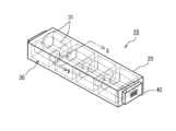
- FIG. 1 is an external view of a battery pack according to the present disclosure
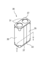
- FIG. 1 is an external view of a battery block according to the present disclosure, and a perspective view of the entire battery block
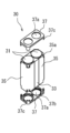
- FIG. FIG. 2 is an external view and partially exploded view of a battery block according to the present disclosure
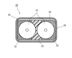
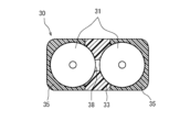
- FIG. FIG. 2 is a cross-sectional view of the battery pack according to the present disclosure in FIG. 1 taken along line XX
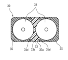
- FIG. 3B is a cross-sectional view taken along the line XX of the battery pack according to the present disclosure in FIG. 1, showing an example of a battery block structure different from that in FIG. 3A
- FIG. 3B is a diagram corresponding to FIGS. 3A and 3B of another battery pack according to the present disclosure
- FIG. 2A and 2B of the battery block according to the present disclosure FIG.
- FIG. 1 is an external view of a battery pack 10 according to the present disclosure.
- the battery pack 10 includes an exterior case 20 made of metal such as aluminum, and one or more battery blocks 30 housed inside the exterior case 20 .
- the exterior case 20 is not limited to being made of metal, and may be made of resin.
- the battery block 30 has a plurality of cells 31 arranged in line, and the plurality of cells 31 are electrically connected to each other.
- the battery block 30 has, for example, a plurality of cells 31 connected in parallel.
- the battery pack 10 is configured such that a plurality of battery blocks 30 are connected in series or in parallel to output a voltage suitable for the device to be used.
- Cell 31 is, for example, a cylindrical battery. In the present disclosure, a cylindrical battery is exemplified as the cell 31, but the battery is not limited to a cylindrical battery, and may be a prismatic battery or the like.
- the cell 31 is a cylindrical battery having a bottomed cylindrical outer can and a sealing member that closes the opening of the outer can.
- An insulating gasket is provided between the outer can and the sealing member.
- the sealing member serves as a positive electrode terminal
- the outer can serves as a negative electrode terminal.
- the sealing member is provided with an exhaust valve for discharging gas when an abnormality occurs in the cell 31 and the internal pressure rises.
- the exhaust valve may be provided at the bottom of the outer can.
- a plurality of cells 31 in the battery block 30 are accommodated in holders.
- the holder of the battery block 30 is composed of a heat insulating member 33, a side member 35 with high thermal conductivity, and the like, which will be described later.
- the holder fixes the arrangement of the plurality of cells 31 and maintains the shape of the battery block 30 .
- the battery pack 10 also includes terminal plates (collector plates) that electrically connect the plurality of battery blocks 30 .
- a positive terminal and a negative terminal of the battery block 30 are connected to the terminal plate, respectively.
- the terminal board may be integrated with the holder.
- An external terminal 40 electrically connected to the battery block 30 is provided at the end of the exterior case 20 .
- the external terminal 40 is used as a terminal for supplying a DC voltage when the battery pack 10 is installed in a device in which it is used.
- the external terminal 40 is also used when charging the battery pack 10 (cell 31).
- the external terminal 40 may be provided only at one end of the battery pack 10, or may be provided at a plurality of locations.
- the heat insulating member 33 or the side member 35 that constitutes the battery block 30 may also serve as the exterior case.
- the battery block 30 has a plurality of cells 31 , heat insulating members 33 , side members 35 and position fixing members 37 .
- the battery block 30 has a heat insulating member 33 arranged between two cells 31, a side member 35 arranged on the side surface of the two cells 31 in the alignment direction, and fixed by a position fixing member 37 sandwiched from above and below.
- FIG. 2A shows a state in which the battery blocks 30 are fixed together.
- FIG. 2B shows the state before the position fixing member 37 is attached.
- the heat insulating member 33 is arranged between the two cells 31 so as to be in contact along the cylindrical side surfaces of the cells 31 .
- the side members 35 are arranged so as to cover the side surfaces of the cells 31 from the opposite side surfaces of the two cells 31 on which the heat insulating members 33 are arranged.
- the side member 35 is divided into a plurality of cells 31 so as to be separated from each other by the heat insulating member 33 .
- the lengths of the heat insulating member 33 and the side member 35 along the axial direction of the cells 31 are formed to be smaller than the lengths of the cells 31 in the axial direction. Therefore, as shown in FIG. 2B, both ends of the cell 31 in the axial direction protrude.
- the position fixing member 37 has a substantially flat plate shape and is mounted on the upper and lower surfaces of the two cells 31 .
- the position fixing member 37 has openings 37 a at positions corresponding to the upper and lower surfaces of the two cells 31 .
- a receiving portion 37 b in which the ends of the cells 31 projecting from the heat insulating member 33 and the side member 35 are received is provided on the side of the opening 37 a of the position fixing member 37 with which the cells 31 abut.
- both ends of the cylindrical axis of the cell 31 constitute electrodes.
- the electrodes of the two cells 31 are electrically connected by a collector plate through the opening 37a of the position fixing member 37 (not shown).
- a fitting claw 37 c is formed at the corner of the position fixing member 37 .
- a fitting concave portion 35 a is formed at a position corresponding to the side member 35 when the position fixing member 37 is placed on the upper surface of the cell 31 .
- the fitting claws 37c of the position fixing member 37 are fitted into the fitting recesses 35a of the side member 35 with the two cells 31 and the heat insulating member 33 sandwiched from both sides, and the ends of the cells 31 are housed in the housing portions 37b. , the battery block 30 is fixed.
- the number of cells 31 in the battery block 30 is not limited to two, and may be three or more. Regarding the arrangement of the plurality of cells 31, it is preferable to arrange them so that the cross-sectional area of the battery block 30 is small, but they may be arranged so as to be arranged in a straight line.
- 2A and 2B show a structure in which the battery block 30 is fixed by the position fixing member 37, but as described later, the battery block 30 is not provided with the position fixing member 37 and is attached to the heat insulating member 33. It is good also as a structure fixed by the side member 35 (refer FIG. 5A, FIG. 5B).
- FIGS. 3A and 3B are cross-sectional views of the battery pack 10 of FIG. 1 taken along line XX.
- the battery block 30 has, for example, the configuration shown in FIG. 2A, but is not limited to this.
- a heat insulating member 33 with low heat conductivity is arranged between the two cells 31 .
- the heat insulating member 33 is made of heat insulating material such as heat insulating resin, foamed resin, foamed concrete, gypsum board, glass wool, or silica airgel.
- the heat-insulating member 33 makes it difficult for the heat generated in the cell 31 to be transmitted to the adjacent adjacent cell 31 .
- a side member 35 having a higher thermal conductivity than the heat insulating member 33 is arranged on the side surface of the cell 31 that is not in contact with the heat insulating member 33 .
- the side member 35 is made of, for example, a highly thermally conductive material containing a thermosetting resin and a thermally conductive filler and/or an endothermic filler. With this configuration, the heat generated in the cells 31 is less likely to be transmitted to the adjacent cells 31 by the heat insulating member 33, and is transmitted to the side members 35 having high thermal conductivity.
- Thermosetting resin is preferable as the resin forming the side member 35 . Since the side members 35 are made of a thermosetting resin, it is possible to prevent the side members 35 from spreading fire when the cells 31 generate abnormal heat, and to ensure the holding function of the cells 31 by the side members 35. can.
- thermosetting unsaturated polyester epoxy resin, melamine resin, phenol resin, thermoplastic polycarbonate, polyethylene, polypropylene, polyvinyl chloride, polystyrene, or the like is used.
- thermally conductive filler metal oxides (eg, aluminum oxide, zinc oxide), metal nitrides (eg, aluminum nitride, boron nitride), and metal oxynitrides (eg, aluminum oxynitride) are used.
- the endothermic filler exhibits an endothermic effect during thermal decomposition, and aluminum hydroxide, magnesium hydroxide, and sodium hydrogen carbonate are used, for example.
- the endothermic filler has the effect of reducing heat generation when the cells 31 generate abnormal heat.
- the battery block 30 is housed so that the side member 35 is in contact with the inner surface of the exterior case 20 on at least one surface. As described above, the heat generated from the cells 31 is transferred to the side member 35 and absorbed. Furthermore, the heat absorbed by the side member 35 is transmitted to the exterior case 20 and radiated from the exterior case 20 to the outside.
- the battery block 30 is configured to fit within the cross section of the exterior case 20.
- a line connecting the centers of the two cells 31 in cross section (alignment direction of the plurality of cells 31)
- An air layer 38 is formed on the side surface perpendicular to the outer case 20 without being in close contact with the exterior case 20 . Since the air layer 38 has a low thermal conductivity, the heat generated from the cells 31 transmitted to the side member 35 is difficult to be transmitted to the air layer 38, and propagates in the lateral direction of FIGS. 3A and 3B in the side member 35. , and is transmitted to the exterior case 20 .
- the heat transferred to the exterior case 20 propagates through the interior of the exterior case 20 and radiates to the outside from the entire periphery of the exterior case 20 .
- the air layer 38 is advantageous in securing the length of the heat conduction path by the outer case 20 between the side member 35 contacting one cell 31 and the side member 35 contacting the other cell 31 . This is advantageous in suppressing heat conduction between the cells 31 when abnormal heat is generated through the heat conduction path of the .
- the exterior case 20 can be formed by connecting a plurality of members. This structure is not particularly limited.
- the heat insulating member 33 may be divided into two, and an air layer 38 may be formed between the two cells 31.
- illustration of the exterior case 20 is omitted.
- FIG. 4 is a diagram showing another heat transfer structure of the battery pack 10.
- a low heat conductive plate member 34 is provided between adjacent cells 31 as a heat insulating member.
- the plate member 34 is made of, for example, heat insulating resin, foam resin, foam concrete, gypsum board, glass wool, or silica airgel material, and is arranged between adjacent cells 31 over the entire axial length of the cells 31 . ing.
- a side member 35 with high thermal conductivity is arranged on the side surface of the cell 31 where the plate member 34 is not arranged.
- the side member 35 of the battery block 30 of the present embodiment has an extending portion 35b that extends from the side surface opposite to the cell 31 where the plate member 34 is arranged, in the direction of the adjacent cell 31. As shown in FIG.
- the extending portions 35b of the two side members 35 are configured to face each other.
- the extending portion 35b has a groove 35c on the tip side and is arranged so as to face each other.
- the plate members 34 are fixed by the side members 35 by fitting the plate members 34 into the grooves 35c provided in the two side members 35 .
- the battery block 30 is fixed with the two cells 31 held between the two side members 35 and the plate member 34 held between the grooves 35c of the two extensions 35b.
- the side member 35 is thermally connected to the inner surface of the exterior case 20 via the high heat conductive adhesive 36 .
- the high thermal conductive adhesive 36 for example, a silicone adhesive containing a high thermal conductive filler is used.
- the high thermal conductive adhesive 36 fixes the battery block 30 inside the outer case 20 and forms a heat transfer path between the side member 35 and the outer case 20 .
- the heat generated in the cells 31 is difficult to transfer due to the heat insulating plates 34 between the adjacent cells 31 .
- a side member 35 is arranged on the opposite side surface of the cell 31 where the plate member 34 is arranged. is transmitted to
- an air layer 38 is formed between the plate member 34 of the battery block 30 and the exterior case 20 other than the side member 35 .
- FIGS. 5A and 5B are diagrams showing the fixing structure of the battery block 30 according to the present disclosure.
- the battery block 30 shown in FIGS. 2A and 2B it is fixed by the position fixing member 37 .
- the battery block 30 of this embodiment has a structure in which it is fixed by a heat insulating member 33 and side members 35 .
- FIG. 5A further includes a connection structure (recessed portion 33a, protruded portion 35d) that fixes the heat insulating member 33 and the side member 35 together.
- the side member 35 has a convex portion 35d that protrudes on the surface facing the heat insulating member 33.
- the convex portion 35d may be provided over the entire length of the cell 31 in the axial direction, or may be provided separately in the axial direction.
- a concave portion 33a is formed in the heat insulating member 33 at a position corresponding to the convex portion 35d.
- FIG. 5B Another fixing structure of the battery block 30 is shown in FIG. 5B.
- the protrusion 35d of the side member 35 is provided along the edge.
- the heat insulating member 33 is provided with a concave portion 33a at a position corresponding to the convex portion 35d.
- the convex portion 35d and the concave portion 33a may be provided over the entire length of the cell 31 in the axial direction, or may be divided in the axial direction, similarly to the battery block 30 of FIG. 5A.
- the plurality of cells 31 in contact with the heat insulating member 33 are sandwiched between the side members 35 from both side surfaces, and the protrusions 35d are fitted into the recesses 33a, whereby the plurality of cells 31 are sandwiched and fixed.
- the battery block 30 shown in FIGS. 5A and 5B can be accommodated in the exterior case 20 to form the battery pack 10, like the battery pack 10 shown in FIGS. 3A and 3B. Alternatively, it may also serve as the exterior case 20 .
Landscapes
- Chemical & Material Sciences (AREA)
- Chemical Kinetics & Catalysis (AREA)
- Electrochemistry (AREA)
- General Chemical & Material Sciences (AREA)
- Engineering & Computer Science (AREA)
- Manufacturing & Machinery (AREA)
- Battery Mounting, Suspending (AREA)
- Secondary Cells (AREA)
Abstract
Description
Claims (10)
- 電池ブロックと、
前記電池ブロックを収納する外装ケースと、
を備え、
前記電池ブロックは、整列配置された複数のセルと、
前記複数のセルの隣接するセル間に設けられる断熱部材と、
前記複数のセルの前記断熱部材が設けられた部位を除く側面に接触して配置される前記断熱部材より熱伝導率が高い側面部材と、を有する、
電池パック。 - 電池ブロックと、
外装ケースと、
を備え、
前記電池ブロックは、整列配置された複数のセルと、
前記複数のセルの隣接するセル間に設けられる断熱部材と、
前記複数のセルの前記断熱部材が設けられた部位を除く側面に接触して配置される前記断熱部材より熱伝導率が高い側面部材と、を有し、
前記側面部材は、前記外装ケースを構成する、
電池パック。 - 前記側面部材は、前記複数のセルにそれぞれ分割して設けられる、
請求項1または2に記載の電池パック。 - 前記側面部材は、前記外装ケースと熱的に接続される、
請求項1に記載の電池パック。 - 前記側面部材は、前記外装ケースの内面に接触している、
請求項1に記載の電池パック。 - 前記側面部材は、前記外装ケースの内面に高熱伝導接着剤を介して熱的に接続されている、
請求項1に記載の電池パック。 - 前記電池ブロックは、前記複数のセルが整列配置される方向に対して垂直方向から、前記複数のセルと前記断熱部材と前記側面部材とを挟んで固定する位置固定部材を有する、
請求項1~6の何れか一項に記載の電池パック。 - 前記断熱部材と前記側面部材は、前記複数のセルを挟持して固定する位置固定部を有する、
請求項1~6の何れか一項に記載の電池パック。 - 前記断熱部材は、前記隣接するセル間の中央に配置される板材であり、
前記側面部材は、前記板材が配置された前記セルの反対側の側面から隣接するセルの方向に回り込んで延び、先端側に溝を有する延出部を有し、
前記板材は、前記溝に嵌めて固定される、
請求項1~8の何れか一項に記載の電池パック。 - 前記隣接するセルの間に空気層を有する、
請求項1~9のいずれか一項に記載の電池パック。
Priority Applications (4)
| Application Number | Priority Date | Filing Date | Title |
|---|---|---|---|
| EP22911139.8A EP4456264A4 (en) | 2021-12-24 | 2022-12-16 | BATTERY PACK |
| CN202280081827.2A CN118369811A (zh) | 2021-12-24 | 2022-12-16 | 电池组 |
| US18/718,522 US20250055076A1 (en) | 2021-12-24 | 2022-12-16 | Battery pack |
| JP2023569409A JPWO2023120436A1 (ja) | 2021-12-24 | 2022-12-16 |
Applications Claiming Priority (2)
| Application Number | Priority Date | Filing Date | Title |
|---|---|---|---|
| JP2021-210755 | 2021-12-24 | ||
| JP2021210755 | 2021-12-24 |
Publications (1)
| Publication Number | Publication Date |
|---|---|
| WO2023120436A1 true WO2023120436A1 (ja) | 2023-06-29 |
Family
ID=86902705
Family Applications (1)
| Application Number | Title | Priority Date | Filing Date |
|---|---|---|---|
| PCT/JP2022/046501 Ceased WO2023120436A1 (ja) | 2021-12-24 | 2022-12-16 | 電池パック |
Country Status (5)
| Country | Link |
|---|---|
| US (1) | US20250055076A1 (ja) |
| EP (1) | EP4456264A4 (ja) |
| JP (1) | JPWO2023120436A1 (ja) |
| CN (1) | CN118369811A (ja) |
| WO (1) | WO2023120436A1 (ja) |
Families Citing this family (1)
| Publication number | Priority date | Publication date | Assignee | Title |
|---|---|---|---|---|
| CN119890626A (zh) * | 2025-03-27 | 2025-04-25 | 宁德时代新能源科技股份有限公司 | 电池单体、电池装置及用电设备 |
Citations (4)
| Publication number | Priority date | Publication date | Assignee | Title |
|---|---|---|---|---|
| JP2012033464A (ja) | 2010-07-02 | 2012-02-16 | Sanyo Electric Co Ltd | パック電池 |
| JP2020181740A (ja) * | 2019-04-25 | 2020-11-05 | パナソニックIpマネジメント株式会社 | 電動工具用の電池パック、電動工具 |
| WO2021019970A1 (ja) * | 2019-07-29 | 2021-02-04 | 三洋電機株式会社 | 電池パック |
| WO2021256093A1 (ja) * | 2020-06-18 | 2021-12-23 | 阿波製紙株式会社 | 断熱シート及びこれを備える電源装置 |
Family Cites Families (3)
| Publication number | Priority date | Publication date | Assignee | Title |
|---|---|---|---|---|
| CN106716675B (zh) * | 2014-10-17 | 2020-02-28 | 三洋电机株式会社 | 电池组 |
| JP2019053816A (ja) * | 2016-01-28 | 2019-04-04 | 三洋電機株式会社 | 電池パック |
| JP6846689B2 (ja) * | 2016-08-24 | 2021-03-24 | パナソニックIpマネジメント株式会社 | 電池モジュール |
-
2022
- 2022-12-16 CN CN202280081827.2A patent/CN118369811A/zh active Pending
- 2022-12-16 EP EP22911139.8A patent/EP4456264A4/en active Pending
- 2022-12-16 JP JP2023569409A patent/JPWO2023120436A1/ja active Pending
- 2022-12-16 WO PCT/JP2022/046501 patent/WO2023120436A1/ja not_active Ceased
- 2022-12-16 US US18/718,522 patent/US20250055076A1/en active Pending
Patent Citations (4)
| Publication number | Priority date | Publication date | Assignee | Title |
|---|---|---|---|---|
| JP2012033464A (ja) | 2010-07-02 | 2012-02-16 | Sanyo Electric Co Ltd | パック電池 |
| JP2020181740A (ja) * | 2019-04-25 | 2020-11-05 | パナソニックIpマネジメント株式会社 | 電動工具用の電池パック、電動工具 |
| WO2021019970A1 (ja) * | 2019-07-29 | 2021-02-04 | 三洋電機株式会社 | 電池パック |
| WO2021256093A1 (ja) * | 2020-06-18 | 2021-12-23 | 阿波製紙株式会社 | 断熱シート及びこれを備える電源装置 |
Non-Patent Citations (1)
| Title |
|---|
| See also references of EP4456264A4 |
Also Published As
| Publication number | Publication date |
|---|---|
| EP4456264A1 (en) | 2024-10-30 |
| CN118369811A (zh) | 2024-07-19 |
| EP4456264A4 (en) | 2025-04-09 |
| US20250055076A1 (en) | 2025-02-13 |
| JPWO2023120436A1 (ja) | 2023-06-29 |
Similar Documents
| Publication | Publication Date | Title |
|---|---|---|
| US11936022B2 (en) | Battery module | |
| JP6847864B2 (ja) | 電池パック | |
| KR102555088B1 (ko) | 이차 전지의 제조 방법 | |
| WO2019151037A1 (ja) | 電池モジュール及び電池パック | |
| CN212991189U (zh) | 电池盒、电池单体、电池和用电设备 | |
| WO2017125985A1 (ja) | 電池モジュール | |
| WO2013021573A1 (ja) | 電池ブロック及び該電池ブロックを有する電池モジュール | |
| JP2019091628A (ja) | リチウムイオン電池モジュール | |
| US20250174810A1 (en) | Battery pack | |
| WO2017130260A1 (ja) | 電池パック | |
| KR20220036171A (ko) | 배터리 모듈 | |
| KR20180071983A (ko) | 파우치형 이차 전지 및 이의 제조 방법 | |
| CN111684621A (zh) | 包括通气构件的袋型电池单元和包括其的电池组 | |
| US20240204347A1 (en) | Battery device | |
| CN112909396B (zh) | 电池单元壳体部及包括该电池单元壳体部的电池模块 | |
| KR20220118635A (ko) | 배터리 팩 | |
| US20200067037A1 (en) | Battery module | |
| JP7216079B2 (ja) | 電源装置 | |
| WO2023120436A1 (ja) | 電池パック | |
| JP2019197662A (ja) | 蓄電装置 | |
| CN219811573U (zh) | 电池及用电装置 | |
| JP4761856B2 (ja) | パック電池 | |
| WO2023162908A1 (ja) | 電池パック | |
| WO2017029865A1 (ja) | 電池パック | |
| US20250132422A1 (en) | Battery pack |
Legal Events
| Date | Code | Title | Description |
|---|---|---|---|
| 121 | Ep: the epo has been informed by wipo that ep was designated in this application |
Ref document number: 22911139 Country of ref document: EP Kind code of ref document: A1 |
|
| WWE | Wipo information: entry into national phase |
Ref document number: 2023569409 Country of ref document: JP |
|
| WWE | Wipo information: entry into national phase |
Ref document number: 18718522 Country of ref document: US Ref document number: 202280081827.2 Country of ref document: CN |
|
| NENP | Non-entry into the national phase |
Ref country code: DE |
|
| ENP | Entry into the national phase |
Ref document number: 2022911139 Country of ref document: EP Effective date: 20240724 |