WO2023120437A1 - 電池パック - Google Patents
電池パック Download PDFInfo
- Publication number
- WO2023120437A1 WO2023120437A1 PCT/JP2022/046502 JP2022046502W WO2023120437A1 WO 2023120437 A1 WO2023120437 A1 WO 2023120437A1 JP 2022046502 W JP2022046502 W JP 2022046502W WO 2023120437 A1 WO2023120437 A1 WO 2023120437A1
- Authority
- WO
- WIPO (PCT)
- Prior art keywords
- height direction
- battery
- partition
- battery pack
- batteries
- Prior art date
- Legal status (The legal status is an assumption and is not a legal conclusion. Google has not performed a legal analysis and makes no representation as to the accuracy of the status listed.)
- Ceased
Links
Images






Classifications
-
- H—ELECTRICITY
- H01—ELECTRIC ELEMENTS
- H01M—PROCESSES OR MEANS, e.g. BATTERIES, FOR THE DIRECT CONVERSION OF CHEMICAL ENERGY INTO ELECTRICAL ENERGY
- H01M50/00—Constructional details or processes of manufacture of the non-active parts of electrochemical cells other than fuel cells, e.g. hybrid cells
- H01M50/20—Mountings; Secondary casings or frames; Racks, modules or packs; Suspension devices; Shock absorbers; Transport or carrying devices; Holders
- H01M50/204—Racks, modules or packs for multiple batteries or multiple cells
- H01M50/207—Racks, modules or packs for multiple batteries or multiple cells characterised by their shape
- H01M50/213—Racks, modules or packs for multiple batteries or multiple cells characterised by their shape adapted for cells having curved cross-section, e.g. round or elliptic
-
- H—ELECTRICITY
- H01—ELECTRIC ELEMENTS
- H01M—PROCESSES OR MEANS, e.g. BATTERIES, FOR THE DIRECT CONVERSION OF CHEMICAL ENERGY INTO ELECTRICAL ENERGY
- H01M50/00—Constructional details or processes of manufacture of the non-active parts of electrochemical cells other than fuel cells, e.g. hybrid cells
- H01M50/20—Mountings; Secondary casings or frames; Racks, modules or packs; Suspension devices; Shock absorbers; Transport or carrying devices; Holders
- H01M50/262—Mountings; Secondary casings or frames; Racks, modules or packs; Suspension devices; Shock absorbers; Transport or carrying devices; Holders with fastening means, e.g. locks
- H01M50/264—Mountings; Secondary casings or frames; Racks, modules or packs; Suspension devices; Shock absorbers; Transport or carrying devices; Holders with fastening means, e.g. locks for cells or batteries, e.g. straps, tie rods or peripheral frames
-
- H—ELECTRICITY
- H01—ELECTRIC ELEMENTS
- H01M—PROCESSES OR MEANS, e.g. BATTERIES, FOR THE DIRECT CONVERSION OF CHEMICAL ENERGY INTO ELECTRICAL ENERGY
- H01M10/00—Secondary cells; Manufacture thereof
- H01M10/60—Heating or cooling; Temperature control
- H01M10/61—Types of temperature control
- H01M10/613—Cooling or keeping cold
-
- H—ELECTRICITY
- H01—ELECTRIC ELEMENTS
- H01M—PROCESSES OR MEANS, e.g. BATTERIES, FOR THE DIRECT CONVERSION OF CHEMICAL ENERGY INTO ELECTRICAL ENERGY
- H01M10/00—Secondary cells; Manufacture thereof
- H01M10/60—Heating or cooling; Temperature control
- H01M10/65—Means for temperature control structurally associated with the cells
- H01M10/653—Means for temperature control structurally associated with the cells characterised by electrically insulating or thermally conductive materials
-
- H—ELECTRICITY
- H01—ELECTRIC ELEMENTS
- H01M—PROCESSES OR MEANS, e.g. BATTERIES, FOR THE DIRECT CONVERSION OF CHEMICAL ENERGY INTO ELECTRICAL ENERGY
- H01M50/00—Constructional details or processes of manufacture of the non-active parts of electrochemical cells other than fuel cells, e.g. hybrid cells
- H01M50/20—Mountings; Secondary casings or frames; Racks, modules or packs; Suspension devices; Shock absorbers; Transport or carrying devices; Holders
- H01M50/204—Racks, modules or packs for multiple batteries or multiple cells
-
- H—ELECTRICITY
- H01—ELECTRIC ELEMENTS
- H01M—PROCESSES OR MEANS, e.g. BATTERIES, FOR THE DIRECT CONVERSION OF CHEMICAL ENERGY INTO ELECTRICAL ENERGY
- H01M50/00—Constructional details or processes of manufacture of the non-active parts of electrochemical cells other than fuel cells, e.g. hybrid cells
- H01M50/20—Mountings; Secondary casings or frames; Racks, modules or packs; Suspension devices; Shock absorbers; Transport or carrying devices; Holders
- H01M50/244—Secondary casings; Racks; Suspension devices; Carrying devices; Holders characterised by their mounting method
-
- H—ELECTRICITY
- H01—ELECTRIC ELEMENTS
- H01M—PROCESSES OR MEANS, e.g. BATTERIES, FOR THE DIRECT CONVERSION OF CHEMICAL ENERGY INTO ELECTRICAL ENERGY
- H01M50/00—Constructional details or processes of manufacture of the non-active parts of electrochemical cells other than fuel cells, e.g. hybrid cells
- H01M50/20—Mountings; Secondary casings or frames; Racks, modules or packs; Suspension devices; Shock absorbers; Transport or carrying devices; Holders
- H01M50/289—Mountings; Secondary casings or frames; Racks, modules or packs; Suspension devices; Shock absorbers; Transport or carrying devices; Holders characterised by spacing elements or positioning means within frames, racks or packs
- H01M50/291—Mountings; Secondary casings or frames; Racks, modules or packs; Suspension devices; Shock absorbers; Transport or carrying devices; Holders characterised by spacing elements or positioning means within frames, racks or packs characterised by their shape
-
- H—ELECTRICITY
- H01—ELECTRIC ELEMENTS
- H01M—PROCESSES OR MEANS, e.g. BATTERIES, FOR THE DIRECT CONVERSION OF CHEMICAL ENERGY INTO ELECTRICAL ENERGY
- H01M50/00—Constructional details or processes of manufacture of the non-active parts of electrochemical cells other than fuel cells, e.g. hybrid cells
- H01M50/20—Mountings; Secondary casings or frames; Racks, modules or packs; Suspension devices; Shock absorbers; Transport or carrying devices; Holders
- H01M50/289—Mountings; Secondary casings or frames; Racks, modules or packs; Suspension devices; Shock absorbers; Transport or carrying devices; Holders characterised by spacing elements or positioning means within frames, racks or packs
- H01M50/293—Mountings; Secondary casings or frames; Racks, modules or packs; Suspension devices; Shock absorbers; Transport or carrying devices; Holders characterised by spacing elements or positioning means within frames, racks or packs characterised by the material
-
- H—ELECTRICITY
- H01—ELECTRIC ELEMENTS
- H01M—PROCESSES OR MEANS, e.g. BATTERIES, FOR THE DIRECT CONVERSION OF CHEMICAL ENERGY INTO ELECTRICAL ENERGY
- H01M50/00—Constructional details or processes of manufacture of the non-active parts of electrochemical cells other than fuel cells, e.g. hybrid cells
- H01M50/30—Arrangements for facilitating escape of gases
- H01M50/342—Non-re-sealable arrangements
- H01M50/3425—Non-re-sealable arrangements in the form of rupturable membranes or weakened parts, e.g. pierced with the aid of a sharp member
-
- H—ELECTRICITY
- H01—ELECTRIC ELEMENTS
- H01M—PROCESSES OR MEANS, e.g. BATTERIES, FOR THE DIRECT CONVERSION OF CHEMICAL ENERGY INTO ELECTRICAL ENERGY
- H01M50/00—Constructional details or processes of manufacture of the non-active parts of electrochemical cells other than fuel cells, e.g. hybrid cells
- H01M50/30—Arrangements for facilitating escape of gases
- H01M50/375—Vent means sensitive to or responsive to temperature
-
- H—ELECTRICITY
- H01—ELECTRIC ELEMENTS
- H01M—PROCESSES OR MEANS, e.g. BATTERIES, FOR THE DIRECT CONVERSION OF CHEMICAL ENERGY INTO ELECTRICAL ENERGY
- H01M50/00—Constructional details or processes of manufacture of the non-active parts of electrochemical cells other than fuel cells, e.g. hybrid cells
- H01M50/50—Current conducting connections for cells or batteries
- H01M50/502—Interconnectors for connecting terminals of adjacent batteries; Interconnectors for connecting cells outside a battery casing
- H01M50/505—Interconnectors for connecting terminals of adjacent batteries; Interconnectors for connecting cells outside a battery casing comprising a single busbar
-
- H—ELECTRICITY
- H01—ELECTRIC ELEMENTS
- H01M—PROCESSES OR MEANS, e.g. BATTERIES, FOR THE DIRECT CONVERSION OF CHEMICAL ENERGY INTO ELECTRICAL ENERGY
- H01M2200/00—Safety devices for primary or secondary batteries
- H01M2200/10—Temperature sensitive devices
-
- H—ELECTRICITY
- H01—ELECTRIC ELEMENTS
- H01M—PROCESSES OR MEANS, e.g. BATTERIES, FOR THE DIRECT CONVERSION OF CHEMICAL ENERGY INTO ELECTRICAL ENERGY
- H01M50/00—Constructional details or processes of manufacture of the non-active parts of electrochemical cells other than fuel cells, e.g. hybrid cells
- H01M50/30—Arrangements for facilitating escape of gases
- H01M50/342—Non-re-sealable arrangements
-
- Y—GENERAL TAGGING OF NEW TECHNOLOGICAL DEVELOPMENTS; GENERAL TAGGING OF CROSS-SECTIONAL TECHNOLOGIES SPANNING OVER SEVERAL SECTIONS OF THE IPC; TECHNICAL SUBJECTS COVERED BY FORMER USPC CROSS-REFERENCE ART COLLECTIONS [XRACs] AND DIGESTS
- Y02—TECHNOLOGIES OR APPLICATIONS FOR MITIGATION OR ADAPTATION AGAINST CLIMATE CHANGE
- Y02E—REDUCTION OF GREENHOUSE GAS [GHG] EMISSIONS, RELATED TO ENERGY GENERATION, TRANSMISSION OR DISTRIBUTION
- Y02E60/00—Enabling technologies; Technologies with a potential or indirect contribution to GHG emissions mitigation
- Y02E60/10—Energy storage using batteries
Definitions
- the present disclosure relates to battery packs.
- Patent Document 1 there is one described in Patent Document 1 as a battery pack.
- This battery pack includes a resin partition member and two heat insulating sheet members made of mica.
- the partition member is arranged between two adjacent cylindrical cells.
- the partition member includes a first curved surface having a shape corresponding to a portion of the side surface of one cylindrical battery, and a second curved surface having a shape corresponding to a portion of the side surface of the other cylindrical battery.
- One sheet member is sandwiched between the side surface of one cylindrical battery and the first curved surface, and the other sheet member is sandwiched between the side surface of the other cylindrical battery and the second curved surface.
- a partition member whose both sides are sandwiched by two heat-insulating sheet members is arranged between two adjacent cylindrical batteries. Therefore, when one cylindrical battery generates abnormal heat, the two sheet members can prevent the heat generated in that cylindrical battery from being conducted to the other cylindrical battery. Therefore, even if one of the cylindrical batteries in the battery pack generates abnormal heat, the other cylindrical batteries are less likely to be affected by the abnormal heat generation.
- an object of the present disclosure is to provide a battery pack that is easy to make compact and easy to improve safety.
- a battery pack includes a restraining member including a side portion arranged to surround at least a portion of a plurality of aligned batteries in the height direction, and two adjacent and a partition member having a head connected to at least one end of the partition in the height direction, wherein the head extends in the height direction of the exhaust valve of the battery. It includes a portion that protrudes from the position, protrudes in the thickness direction of the partition, and overlaps at least one of the two batteries in the height direction. Note that the height direction may be defined as the axial direction of any one battery.
- the distance between adjacent batteries can be easily shortened and the size can be easily reduced, the influence of abnormal heat generation of batteries can be effectively suppressed from affecting other batteries, and safety can be enhanced. easy.
- FIG. 1 is a perspective view showing the internal structure of a battery pack according to an embodiment of the present disclosure
- FIG. 3 is a schematic cross-sectional view of the battery pack
- FIG. 4 is a plan view of the first restraint member of the battery pack when viewed from the outside on one side in the height direction
- FIG. 3 is a cross-sectional view taken along line AA of FIG. 2
- FIG. 4 is a cross-sectional view of the periphery of a projecting terminal in a battery pack of a reference example
- FIG. 4 is a cross-sectional view of the vicinity of the protruding terminal in the battery pack of the embodiment
- FIG. 11 is a cross-sectional view of the vicinity of the protruding terminal of the battery pack of the modified example
- FIG. 8 is a cross-sectional view corresponding to FIG. 7 in a battery pack of another modified example
- FIG. 11 is a plan view of a partition member of a battery pack of another modification when viewed from the opposite side of the head in the height direction
- FIG. 11 is a perspective view of a restraining member of a battery pack of a further modified example
- FIG. 11 is a plan view of the outer surface of the top plate portion of the restraining member of the battery pack of the further modified example when viewed from the height direction
- FIG. 10 is a plan view of the inner surface of the top plate portion of the battery pack of the further modified example when viewed from the height direction
- FIG. 11 is a perspective view of a partition member of a battery pack of a further modified example
- the height direction is a direction parallel to the axial direction of the battery 40 partitioned by the partition members 70, 170, 270, 370 and parallel to the central axis of the battery.
- the battery includes a bottomed cylindrical outer can 41 (see FIG. 2), an electrode body (not shown) arranged in the outer can 41, and an insulating gasket (A cylindrical battery 40 (see FIG. 2) having a sealing body 42 (see FIG. 2) that seals via a (not shown) will be described. Also, a case where the sealing member 42 has an exhaust valve that is broken when the cylindrical battery 40 is abnormally heated to exhaust high-temperature gas in the cylindrical battery 40 will be described.
- the battery may be a cylindrical battery having exhaust valves on both the sealing member and the bottom of the outer can, or may be a cylindrical battery having an exhaust valve only on the bottom of the outer can.
- the battery may not be a cylindrical battery, but may be, for example, a prismatic battery.
- FIG. 1 is a perspective view showing the internal structure of a battery pack 1 according to an embodiment of the present disclosure.
- the battery pack 1 includes a case 5 and one or more battery blocks 10 housed within the case 5 .
- the case 5 is made of, for example, a metal material such as aluminum or a resin material.
- the battery block 10 has a plurality of cylindrical batteries (hereinafter simply referred to as batteries) 40 arranged substantially parallel to each other at approximately the same position in the height direction. connected to The multiple batteries 40 may be connected in parallel, connected in series, or electrically connected using both parallel and series connections.
- the battery block 10 has two batteries 40 connected in parallel.
- the battery pack 1 has a connection structure for electrically connecting the plurality of battery blocks 10 .
- connection structure may include, for example, at least one of one or more wires and one or more bus bars, at least one of which may be accommodated in an internal chamber defined by the case 5, and the case 5 may be made of resin. If configured, it may be recessed within the case 5 . Alternatively, at least one of them may have both a portion accommodated in the internal chamber defined by the case 5 and a portion embedded in the resin case 5 .
- the plurality of battery blocks 10 are electrically connected in at least one of series connection and parallel connection by the connection structure.
- the voltage of the battery pack 1 can be increased.
- the capacity of the battery pack 1 can be increased.
- the case 5 is provided with external terminals 7 that are exposed to the outside and connectable from the outside.
- the external terminals 7 are electrically connected to the plurality of battery blocks 10 via the connection structure.
- the external terminal 7 is used as a terminal for supplying DC voltage when the battery pack 1 is mounted on a device such as a power-assisted bicycle.
- the external terminal 7 may be used when charging the battery 40 included in the battery pack 1 .
- the external terminal 7 may be provided at only one location on the case 5 or may be provided at a plurality of locations on the case 5 .
- FIG. 2 is a schematic cross-sectional view of the battery pack 1.
- the battery block 10 includes a holder 15 that holds two batteries 40 together.
- the holder 15 positions the second battery 40 relative to the first battery 40 and prohibits the second battery 40 from moving relative to the first battery 40 .
- Each of the first battery 40 and the second battery 40 has a protruding terminal 43 protruding to one side in the height direction at the center of the end face on one side in the height direction.
- the holder 15 includes a first restraining member 50, a second restraining member 60, and a partition member 70 having a lower thermal conductivity than the two restraining members 50,60.
- Each of the first and second restraining members 50 and 60 is made of, for example, high thermal conductive PPS (polyphenylene sulfide) resin, resin containing heat dissipation filler, or the like.
- the partition member 70 is made of, for example, an injection-moldable thermosetting resin, and more specifically, made of phenolic resin, unsaturated polyester, unsaturated polyester mixed with a heat-absorbing agent, or the like. can be done.
- the partition member 70 may be made of an inorganic mineral such as mica, or a material obtained by mixing an inorganic mineral such as mica into a resin material.
- the first restraining member 50 is made of integral resin.
- the first restraining member 50 includes an annular side portion 51 and a covering portion 52 .
- the first restraining member 50 is arranged to surround the ends on one side in the height direction of the portions of the two batteries 40 other than the projecting terminals 43 .
- the covering portion 52 extends in an orthogonal direction that is substantially perpendicular to the height direction, and covers part of the end surface of the battery 40 on one side in the height direction.
- the first binding member 50 holds the two batteries 40 by binding the protruding terminal 43 side in the height direction of the battery set 45 composed of the two batteries 40 included in the battery block 10 . Note that the battery 40 used in the embodiment shown in FIG.
- FIG. 3 is a plan view of the first restraint member 50 viewed from the outside on one side in the height direction.
- a dotted line 8 in FIG. 3 indicates the position of the outer edge of the outer can 41 of the battery 40 .
- the covering portion 52 of the first restraining member 50 has a substantially rectangular planar shape and has two substantially identical cylindrical holes 53 and 54 .
- the two cylindrical holes 53 and 54 are through holes and are spaced apart in the longitudinal direction of the covering portion 52 .
- the first cylindrical hole 53 accommodates the protruding terminal 43 having the exhaust valve of the first battery 40 and is used for wiring that connects the electrode of the first battery 40 and the current collector plate.
- the first battery 40 and the second battery 40 face each other in the longitudinal direction with a gap therebetween in a state in which the protruding terminals 43 of the corresponding batteries 40 are accommodated in the first and second cylindrical holes 53 and 54 .
- the first cylindrical hole 53 accommodates the exhaust valve of the first battery 40
- the second cylindrical hole 54 accommodates the exhaust valve of the second battery 40.
- the covering part 52 has a partition setting hole 55 which is arranged at intervals in both of the two cylindrical holes 53 and 54 in the central part in the longitudinal direction.
- the partition installation hole 55 is a through hole, extends in the width direction of the covering portion 52, and has a substantially rectangular planar shape.
- the covering portion 52 has two protruding portions 56 and 57 projecting toward the center of the partition setting hole 55 in the longitudinal direction at both ends of the partition setting hole 55 in the longitudinal direction (matching the width direction of the covering portion 52). .
- the first projecting portion 56 and the second projecting portion 57 are spaced apart in the width direction of the partition setting hole 55 (matching the longitudinal direction of the covering portion).
- there is a through recess 59 that is rectangular in plan view.
- the through recessed portion 59 is positioned in the center portion of the partition setting hole 55 in the width direction.
- first projecting portion on one longitudinal side of the partition setting hole and the first projecting portion on the other longitudinal direction side of the partition setting hole may be connected and integrated.
- second projecting portion on the other longitudinal direction side of the partition setting hole and the second projecting portion on the other longitudinal direction side of the partition setting hole may be connected to be integrated.
- a rectangular through-hole may be provided in the widthwise central portion of the partition installation hole.
- the thickness (dimension in the height direction) of the first and second projecting portions 56 and 57 is thinner than the thickness (dimension in the height direction) of the covering portion 52 .
- the lower surfaces of the first and second projecting portions 56 and 57 on the battery 40 side and the lower surface of the covering portion 52 on the battery side are positioned on the same plane. Accordingly, above the upper surfaces of the first and second projecting portions 56 and 57 in the partition setting hole 55, a head accommodating chamber 69 having a substantially rectangular cross section is provided above the upper surfaces of the first and second projecting portions 56 and 57 in the partition setting hole 55. 3, if there are projections 56 and 57 in the gaps between the batteries 10, the positions in the height direction can be freely determined.
- the lower surface of the projecting portions 56 and 57 on the battery 40 side and the lower surface of the covering portion 52 on the battery side need not be positioned on the same plane.
- the second restraining member 60 has a different structure from the first restraining member 50 in that the partition installation hole 55 does not exist.
- the second restraining member 60 includes an annular side portion 61 and a covering portion 62 .
- the side portion 61 is arranged to surround the ends of the two batteries 40 on the other side in the height direction.
- the covering portion 62 extends in the orthogonal direction substantially orthogonal to the height direction, and covers a part of the end surface of the battery 40 on the other side in the height direction.
- the second restraint member 60 restrains the bottom side in the height direction of the battery set 45 and prevents the two batteries 40 from being separated at the bottom side in the height direction.
- the first cylindrical hole 63 in the second restraining member 60 is a through hole and overlaps the center of the bottom surface of the outer can 41 of the first battery 40 in the height direction.
- the second cylindrical hole 64 in the second restraint member 60 is a through hole, and overlaps with the central portion of the bottom surface of the outer can 41 of the second battery 40 in the height direction.
- the cylindrical holes 63 and 64 are used, for example, to electrically connect the first battery 40 to the second battery 40 and to electrically connect the battery block 10 to the battery blocks 10 adjacent in the height direction.
- two batteries 40 included in the battery block 10 are connected in parallel, and two battery blocks 10 adjacent in the height direction are connected in series. An example of a connection structure that enables such electrical connection will be briefly described later.
- the partition member 70 includes a partition portion 71 that partitions the two adjacent batteries 40, 40 included in the battery block 10, and a head portion 72 that is connected to at least one end of the partition portion 71 in the height direction. have.
- the head 72 is arranged at the end of the battery 40 having the exhaust valve.
- the partition part 71 has a rectangular plate shape in plan view, and the head part 72 has a block structure and a rectangular parallelepiped shape.
- the partition member 70 has a shape substantially symmetrical with respect to a plane P perpendicular to the thickness direction of the partition 71 and bisecting the partition 71 .
- the widthwise length of the partitioning portion 71 is smaller than the widthwise length of the head portion 72 . Therefore, the head portion 72 protrudes to both sides in the thickness direction of the partition portion 71 and is thicker than the partition portion 71 .
- the head portion 72 may be made to be thicker than the partition portion 71 by protruding only to one side of the partition portion 71 in the thickness direction.
- the head portion 72 protrudes from the position of the exhaust valve of the battery 40 in the height direction of the partition portion 71, and protrudes from the partition portion 71 in the thickness direction to overlap the first battery 40 in the height direction. , and a second portion 92 that protrudes from the partition portion 71 in the thickness direction and overlaps the second battery 40 in the height direction.
- the head 72 includes a top surface 73 located on one side in the height direction and a bottom surface 74 located on the other side in the height direction. Each of the top surface 73 and the bottom surface 74 extends in an orthogonal direction substantially orthogonal to the height direction.
- the widthwise length (thickness) of the partition portion 71 of the partition member 70 is substantially the same as the width of the through recess 59 (see FIG. 3), and the shape and thickness of the head portion 72 when viewed from the height direction.
- the size substantially matches the shape and size of the partition installation hole 55 when viewed from the height direction.
- the partitioning portion 71 of the partitioning member 70 is press-fitted into the through recess 59 , and the head portion 72 is pushed into the head receiving chamber 69 until the bottom surface 74 of the head portion 72 contacts the upper surfaces of the first and second projecting portions 56 and 57 . housed in In this manner, the partition member 70 is attached to the first restraint member 50 .
- the first surface 81 of the partition member 70 contacts the first batteries 40 and the second surface 82 of the partition member 70 contacts the second batteries 40 .
- the first surface 81 applies force to the first battery 40 in the direction normal to the first surface 81
- the second surface 82 applies force to the second battery 40 in the direction normal to the second surface 82 .
- the first and second batteries 40 are sandwiched between the side portions 51 and 61 and the partition portion 71 and positioned in the orthogonal direction.
- a tip surface 83 of the partition member 70 on the side opposite to the head 72 side is in contact with the inner bottom surface 65 of the second restraint member 60 .
- FIG. 4 is a cross-sectional view taken along the line AA in FIG. 2, and is a cross-sectional view showing a cross section on one side in the height direction when the partition member 70 is cut along the plane P.
- the partition member 70 has a height direction extending portion 77 extending in the height direction from the head portion 72 and a portion of the height direction extending portion 77 facing the head portion 72 in the height direction. It has a facing portion 78 that is connected to the opposite end and faces the head portion 72 in the height direction with a gap therebetween. Head 72 , heightwise extension 77 , and opposing portion 78 define slit 84 .
- the battery pack 1 further includes a collector plate 67 and a sheet member 68.
- the current collecting plate 67 is made of a conductive material such as metal, such as aluminum or nickel. At least part of the current collector plate 67 is accommodated in the slit 84 .
- the sheet member 68 is made of a fireproof sheet or a noncombustible sheet, such as a thermosetting resin (eg, phenol resin, unsaturated polyester resin, silicone resin, polyurethane resin, etc.) or a noncombustible material (eg, inorganic minerals, ceramics, metals, etc.). At least part of the sheet member 68 is accommodated between the collector plate 67 and the facing portion 78 in the slit 84 .
- a thermosetting resin eg, phenol resin, unsaturated polyester resin, silicone resin, polyurethane resin, etc.
- a noncombustible material eg, inorganic minerals, ceramics, metals, etc.
- the current collecting plate 67 has a first cut-and-raised portion 67a at a position overlapping the first cylindrical hole 53 in the height direction.
- the protruding terminal 43 of 40 is pressed to come into contact with the protruding terminal 43 .
- the current collector plate 67 has a second cut-and-raised portion 67b at a position overlapping the second cylindrical hole 54 in the height direction.
- the projecting terminal 43 is pressed to come into contact with the projecting terminal 43 .
- a plurality of battery blocks 10 are arranged in a row in the height direction.
- the bottom of the outer can 41 of each battery 40 of one battery block is connected to the current collector plate 67 of the other battery block 10 by a bus bar 95. electrically connected.
- the current collecting plate 67 of the battery block 10 located at one end in the height direction of the battery pack 1 is electrically connected to one electrode of the external terminal 7 (not shown in FIG.
- the battery pack 1 has a partition contact portion that contacts at least one end of the partition member 70 in the height direction. Specifically, the top surface 78 a of the facing portion 78 forming one end in the height direction of the partition member 70 of the battery block 10 illustrated at the top of FIG. 2 contacts the inner surface of the case 5 . ing. Therefore, the portion 98 of the case 5 that is in contact with the top surface 78a serves as a partition contact portion.
- the top surface 78a of the facing portion 78 forming one end in the height direction of the partition member 70 of the battery block 10 positioned second from the top in FIG. contact with the bottom surface 60a of the second restraint member 60 of the battery block 10 that is in contact with the battery block 10. Therefore, the portion 99 of the bottom surface 60a of the second restraint member 60 of the battery block 10 that contacts the top surface 78a of the opposing portion 78 of the adjacent battery block 10 also serves as a partition contact portion.
- the battery pack 1 includes the restraining members 50 and 60 including the side portions 51 and 61 arranged to surround at least a portion of the aligned batteries 40 in the height direction.
- the battery pack 1 also includes a partition member 70 having a partition portion 71 that partitions two adjacent batteries 40 and a head portion 72 that is connected to at least one end of the partition portion 71 in the height direction.
- the head portion 72 has portions 91 and 92 that protrude in the height direction from the position of the exhaust valve of the battery 40 and also protrude in the thickness direction of the partition portion 71 so as to overlap at least one of the two batteries 40 in the height direction. including.
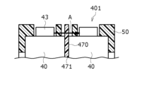
- FIG. 5 is a cross-sectional view around the projecting terminal 43 in the battery pack 401 of the reference example
- FIG. 6 is a cross-sectional view around the projecting terminal 43 in the battery pack 1 .
- partition member 470 that partitions two adjacent batteries 40 does not have a head but has only plate-like partition 471 . It differs from the battery pack 1 in that it is partitioned by a plate-like partition 471 .
- the partition member 70 has the block-shaped head portion 72 thicker than the partition portion 71 on one side in the height direction of the partition portion 71, so that one battery 40 is abnormal. Even if the heat is generated and the exhaust valve is operated, the head 72 can block high-temperature gas and spouts emitted from the vicinity of the protruding terminal 43 in the direction indicated by the arrow B in FIG. Therefore, it is possible to effectively prevent the high-temperature gas and ejected matter from reaching the adjacent battery 40 .
- the thickness of the partition 71 that partitions the adjacent batteries 40 can be set independently of the thickness required for the head 72. It is not necessary to increase the dimension (perpendicular direction), and the battery pack 1 can be easily configured to be compact.
- the head portion 72 includes a first portion 91 that protrudes on both sides in the thickness direction of the partition portion 71 and overlaps one of the two adjacent batteries 40, 40 in the height direction, and a first portion 91 that overlaps the two batteries 40, 40 and a second portion 92 overlapping in the height direction with the other of the two.
- the dimension of the head 72 in the thickness direction can be increased. Therefore, when one battery 40 generates abnormal heat, the effect of suppressing the other battery 40 from being affected can be made remarkable.
- the head 72 has a first portion 91 that overlaps one of the two batteries 40 and 40 in the height direction, and a second portion 92 that overlaps the other of the two batteries 40 and 40 in the height direction.
- the head may have a portion that overlaps one of the two adjacent batteries in the height direction and no portion that overlaps the other of the two batteries in the height direction.
- the partition member 70 has a height direction extension portion 77 extending in the height direction from the head portion 72 and an end portion of the height direction extension portion 77 opposite to the head portion 72 side in the height direction. and facing the head 72 in the height direction with a gap therebetween.
- the head 72 , the heightwise extending portion 77 and the facing portion 78 may also define the slit 84 .
- the battery pack 1 may include the collector plate 67 at least partially accommodated in the slit 84 .
- the adjacent batteries 40 , 40 can be easily electrically connected using the current collector plate 67 .
- the adjacent batteries 40 , 40 are arranged in the same direction, and the adjacent batteries 40 , 40 are connected in parallel by the current collector plate 67 .
- adjacent batteries may be arranged opposite to each other, and adjacent batteries may be connected in series by current collector plates.
- the battery pack 1 may include a fire-resistant sheet member 68 at least partially accommodated between the collector plate 67 and the facing portion 78 in the slit 84 .
- the sheet member 68 can more effectively suppress the influence of abnormal heat generation of one battery from affecting the other batteries, and the battery pack 1 can be made even safer. It should be noted that a structure in which only a part of the current collector plate is accommodated in the slit without the sheet member having fire resistance may be used.
- the battery pack 1 may include a partition contact portion that contacts at least one end of the partition member 70 in the height direction.
- the partition member 70 may have a lower thermal conductivity than the restraining members 50 and 60.
- the heat from the abnormally heated battery 40 can be effectively radiated to the outside through the restraining members 50 and 60 with high thermal conductivity. Therefore, it is possible to effectively prevent the other batteries 40 from being affected by the abnormally heated battery 40 .
- the battery pack 1 may include a case 5 that accommodates the restraining members 50 and 60 .
- the thermal conductivity of the partition member 70 is lower than the thermal conductivity of the restraining members 50 and 60 has been described.
- the thermal conductivity of the partition member may be the same as the thermal conductivity of the restraint member, or may be higher than the thermal conductivity of the restraint member.
- partition member 170 may have a T-shape in cross section, as shown in FIG. That is, the partition member 170 may not have the height direction extending portion and the facing portion, and the head portion 72 may form one end portion of the partition member 170 in the height direction. 6, illustration of the height-direction extending portion 77 and the facing portion 78 that constitute the slit 84 is omitted.
- the restraining member may be a case.
- the partition member 70 is integrally molded with the same resin material.
- the partition member may be made of a different material for the partition portion and the head portion.
- the partition member may be made integrally by two-color molding.
- the partition member is formed by joining the partition made of the same material and the head made of a material different from that of the partition by a joining means such as an adhesive or a welded portion. good too.
- one of the partition and the head may be made of an inorganic mineral such as mica, or a material obtained by mixing an inorganic mineral such as mica into a resin material.
- one of the partition and the head may be made of a thermosetting resin (for example, phenolic resin, unsaturated polyester resin, silicone resin, etc.) or ceramic fiber sheet material.
- FIG. 8 is a cross-sectional view corresponding to FIG. 7 in battery pack 201 of another modification
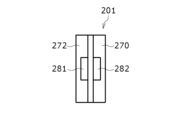
- FIG. 9 is a view of partition member 270 of battery pack 201 from the opposite side of head 272 in the height direction.
- the head 272 has a first recess 255 on the end face of the first portion 291 facing the battery 40 and a second recess 256 on the end face of the second portion 292 facing the battery 40.
- fixing means 281, 282 for example, an adhesive, an adhesive, or an adhesive sheet such as double-sided tape may be accommodated in the first and second recesses 255, 256, respectively.
- the first fixing means 281 may be fixed to both the inner surface of the first recess 255 and the end surface of the battery 40, and the second fixing means 282 may be fixed to both the inner surface of the second recess 256 and the end surface of the battery 40. .
- the partition member 270 can be fixed to both of the two adjacent batteries 40, the partition member 270 can be prevented from moving relative to each of the two adjacent batteries 40, and each battery 40 can be Relative rotation with respect to the partition member 270 can be prevented.
- a first fixing means such as an adhesive, a pressure-sensitive adhesive, or a double-sided tape is inserted between the first portion of the head portion and the end surface of the battery without providing a concave portion on the end surface of the first portion of the head portion on the battery side. of adhesive sheets may be placed.
- a second fixing means such as an adhesive, a pressure-sensitive adhesive, or the like is provided between the second portion of the head portion and the end surface of the battery without providing a concave portion on the end surface of the second portion of the head portion on the battery side.
- An adhesive sheet such as double-sided tape may be arranged. In this manner, the first portion may be secured to the first battery and the second portion may be secured to the second battery.
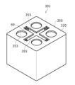
- FIG. 10 is a perspective view of restraining member 350 of battery pack 301 of a further modified example
- FIG. It is a top view
- 12 is a plan view of inner surface 322 of top plate portion 320 of battery pack 301 viewed from the height direction
- FIG. 13 is a perspective view of partition member 370 of battery pack 301. As shown in FIG.
- the restraining member 350 may have a substantially rectangular parallelepiped internal chamber and a substantially rectangular parallelepiped external appearance.
- a plus-shaped (+-shaped) partition installation hole 355 may be provided in the top plate portion 320, and each of the four ends of the partition installation hole 355 may have a shape as shown in FIG. The first projecting portion 56, the second projecting portion 57, and the through recess 59 described with reference to FIG.
- cylindrical holes 353 for accommodating protruding terminals 43 (or exhaust valves) of the batteries 40 are provided in each of four portions separated by plus-shaped partition installation holes 355 in the top plate portion 320 having a rectangular planar shape. good too.
- the bottom plate portion (not shown) may also be provided with cylindrical holes (not shown) around positions facing the four cylindrical holes 353 in the height direction.
- recesses 315 for accommodating the ends of the batteries 40 in the height direction may be provided on the inner surface 322 of the top plate 320 and the inner surface of the bottom plate. It may have a battery restraint surface 318 having a shape corresponding to a part of the outer peripheral surface.
- the partition member 370 has an integral structure, and the partition portion 371 has a positive shape when viewed from the height direction, and the partition portion 371 has a positive shape when viewed from the height direction.
- a plus-shaped head 372 may be included.
- the partition part 371 may have a quadrangular prism whose end face shape is a square and four plate-shaped parts 340 radially extending from each side face of the quadrangular prism at intervals of 90 degrees.
- the head portion 372 has a first plate-shaped portion 345 with a square end face shape and four second plate-shaped portions 347 radially extending from each side surface of the first plate-shaped portion 345 at intervals of 90 degrees.
- one side end in the height direction of the second plate-like portion 347 of the head portion 372 and one side end in the height direction of the plate-like portion 340 of the partition portion 371 may be connected.
- the second plate-shaped portion 347 of the head portion 372 and the plate-shaped portion 340 of the partition portion 371, which form a pair, are the same as the head portion 72 and the partition portion 71 described above with reference to FIGS. It may have the same structure as the one-piece structure. That is, the second plate-like portion 347 of the head portion 372 may have portions that protrude on both sides in the thickness direction of the plate-like portion 340 of the partition portion 371 .
- each plate-like portion 340 of the partition portion 371 is press-fitted into the through recess 59 until the bottom surface of the head portion 372 contacts the first and second projecting portions 56 and 57, and each second plate-like portion of the head portion 372 is pressed.
- the portion 347 may be housed in the head housing chamber 69 (see FIG. 10). In this way, a battery block having four batteries 40 arranged in two rows and two columns can be constructed.
- adjacent batteries may have different positions in the height direction.
- the protruding terminals of one battery may protrude in the height direction from the bottom of the outer can of the other battery at both ends.
- FIG. 2 the case where all of the top surface 73 of the head 72 in the height direction and all of the bottom surface 74 of the head 72 are substantially parallel has been described, but this is not the case. It doesn't have to be. If the head portion of the partition member protrudes in the height direction from the position of the exhaust valve of the battery and includes a portion that protrudes in the thickness direction of the partition portion and overlaps at least one of the two batteries in the height direction, It can be of any shape and construction.
- the partition member 70 has the head 72 on the protruding terminal 43 side of the battery 40 in the height direction.
- the partition member may have a head on the side opposite to the projecting terminal side of the battery in the height direction of the partition.
- the battery may have a vent valve at the bottom of the outer can.
- the partition member may have heads on both sides of the partition in the height direction.
- a battery may have exhaust valves at two locations, the seal and the bottom of the outer can. In such a case, by adopting this structure, it is possible to effectively prevent the high-temperature gas and spouts released from the sealing member and the bottom of the outer can from reaching the adjacent battery.
Landscapes
- Chemical & Material Sciences (AREA)
- Chemical Kinetics & Catalysis (AREA)
- Electrochemistry (AREA)
- General Chemical & Material Sciences (AREA)
- Engineering & Computer Science (AREA)
- Manufacturing & Machinery (AREA)
- Battery Mounting, Suspending (AREA)
Abstract
Description
Claims (9)
- 整列配置された複数の電池における高さ方向の少なくとも一部を取り囲むように配置される側方部を含む拘束部材と、隣り合う2つの前記電池の間を仕切る仕切部、及び前記仕切部の前記高さ方向の少なくとも一方側の端部に接続される頭部を有する仕切部材と、を備え、
前記頭部は、前記高さ方向に前記電池の排気弁の位置より突出し、かつ前記仕切部の厚さ方向に突出して前記2つの電池のうち少なくとも一方に前記高さ方向に重なる部分を含む、電池パック。 - 前記頭部は、前記仕切部の厚さ方向の両側に突出して前記2つの電池のうちの一方に前記高さ方向に重なる第1部分と、前記2つの電池のうちの他方に前記高さ方向に重なる第2部分とを含む、請求項1に記載の電池パック。
- 前記仕切部材が、前記頭部から前記高さ方向に延在する高さ方向延在部と、前記高さ方向延在部における前記高さ方向の前記頭部側とは反対側の端部に接続されると共に前記頭部に隙間を介して前記高さ方向に対向する対向部とを有して、前記頭部、前記高さ方向延在部、及び前記対向部が、スリットを画定し、
少なくとも一部が前記スリットに収容される集電板を備える、請求項1または2に記載の電池パック。 - 少なくとも一部が前記スリットにおける前記集電板と前記対向部の間に収容され、耐火性を有するシート部材を備える、請求項3に記載の電池パック。
- 前記仕切部材における前記高さ方向の少なくとも一方側の端部に接触する仕切接触部を備える、請求項1から4のいずれか1つに記載の電池パック。
- 前記仕切部材が、前記拘束部材よりも熱伝導率が低い、請求項1から5のいずれか1つに記載の電池パック。
- 前記第1部分と前記2つの電池のうちの一方との間に配置される第1固定手段と、
前記第2部分と前記2つの電池のうちの他方との間に配置される第2固定手段と、
を備える、請求項2から6のいずれか1つに記載の電池パック。 - 前記拘束部材を収容するケースを備える、請求項1から7のいずれか1つに記載の電池パック。
- 前記拘束部材が、ケースを構成する、請求項1から7のいずれか1つに記載の電池パック。
Priority Applications (4)
| Application Number | Priority Date | Filing Date | Title |
|---|---|---|---|
| US18/719,865 US20250192320A1 (en) | 2021-12-24 | 2022-12-16 | Battery pack |
| CN202280084473.7A CN118435434A (zh) | 2021-12-24 | 2022-12-16 | 电池包 |
| JP2023569410A JPWO2023120437A1 (ja) | 2021-12-24 | 2022-12-16 | |
| EP22911140.6A EP4456284A4 (en) | 2021-12-24 | 2022-12-16 | BATTERY PACK |
Applications Claiming Priority (2)
| Application Number | Priority Date | Filing Date | Title |
|---|---|---|---|
| JP2021-211278 | 2021-12-24 | ||
| JP2021211278 | 2021-12-24 |
Publications (1)
| Publication Number | Publication Date |
|---|---|
| WO2023120437A1 true WO2023120437A1 (ja) | 2023-06-29 |
Family
ID=86902708
Family Applications (1)
| Application Number | Title | Priority Date | Filing Date |
|---|---|---|---|
| PCT/JP2022/046502 Ceased WO2023120437A1 (ja) | 2021-12-24 | 2022-12-16 | 電池パック |
Country Status (5)
| Country | Link |
|---|---|
| US (1) | US20250192320A1 (ja) |
| EP (1) | EP4456284A4 (ja) |
| JP (1) | JPWO2023120437A1 (ja) |
| CN (1) | CN118435434A (ja) |
| WO (1) | WO2023120437A1 (ja) |
Cited By (1)
| Publication number | Priority date | Publication date | Assignee | Title |
|---|---|---|---|---|
| WO2024024422A1 (ja) * | 2022-07-26 | 2024-02-01 | パナソニックIpマネジメント株式会社 | 電池パック |
Citations (5)
| Publication number | Priority date | Publication date | Assignee | Title |
|---|---|---|---|---|
| JP2012033464A (ja) | 2010-07-02 | 2012-02-16 | Sanyo Electric Co Ltd | パック電池 |
| JP2016046234A (ja) * | 2014-08-27 | 2016-04-04 | 三洋電機株式会社 | バッテリシステム |
| WO2018225609A1 (ja) * | 2017-06-08 | 2018-12-13 | 三洋電機株式会社 | 電池モジュール |
| JP2018206605A (ja) * | 2017-06-05 | 2018-12-27 | 積水化学工業株式会社 | 熱暴走防止シート |
| JP2020166991A (ja) * | 2019-03-28 | 2020-10-08 | 三洋電機株式会社 | 電池パック |
Family Cites Families (2)
| Publication number | Priority date | Publication date | Assignee | Title |
|---|---|---|---|---|
| WO2010098067A1 (ja) * | 2009-02-24 | 2010-09-02 | パナソニック株式会社 | 電池モジュールとそれを用いた電池モジュール集合体 |
| CN109643776B (zh) * | 2016-11-30 | 2022-05-24 | 松下知识产权经营株式会社 | 电池模块 |
-
2022
- 2022-12-16 CN CN202280084473.7A patent/CN118435434A/zh active Pending
- 2022-12-16 WO PCT/JP2022/046502 patent/WO2023120437A1/ja not_active Ceased
- 2022-12-16 JP JP2023569410A patent/JPWO2023120437A1/ja active Pending
- 2022-12-16 EP EP22911140.6A patent/EP4456284A4/en active Pending
- 2022-12-16 US US18/719,865 patent/US20250192320A1/en active Pending
Patent Citations (5)
| Publication number | Priority date | Publication date | Assignee | Title |
|---|---|---|---|---|
| JP2012033464A (ja) | 2010-07-02 | 2012-02-16 | Sanyo Electric Co Ltd | パック電池 |
| JP2016046234A (ja) * | 2014-08-27 | 2016-04-04 | 三洋電機株式会社 | バッテリシステム |
| JP2018206605A (ja) * | 2017-06-05 | 2018-12-27 | 積水化学工業株式会社 | 熱暴走防止シート |
| WO2018225609A1 (ja) * | 2017-06-08 | 2018-12-13 | 三洋電機株式会社 | 電池モジュール |
| JP2020166991A (ja) * | 2019-03-28 | 2020-10-08 | 三洋電機株式会社 | 電池パック |
Non-Patent Citations (1)
| Title |
|---|
| See also references of EP4456284A4 |
Cited By (1)
| Publication number | Priority date | Publication date | Assignee | Title |
|---|---|---|---|---|
| WO2024024422A1 (ja) * | 2022-07-26 | 2024-02-01 | パナソニックIpマネジメント株式会社 | 電池パック |
Also Published As
| Publication number | Publication date |
|---|---|
| EP4456284A1 (en) | 2024-10-30 |
| CN118435434A (zh) | 2024-08-02 |
| US20250192320A1 (en) | 2025-06-12 |
| EP4456284A4 (en) | 2025-04-16 |
| JPWO2023120437A1 (ja) | 2023-06-29 |
Similar Documents
| Publication | Publication Date | Title |
|---|---|---|
| JP7186371B2 (ja) | 電池ブロック | |
| US11128012B2 (en) | Battery module including thermal insulator disposed between battery blocks | |
| CN111033810B (zh) | 电池模块 | |
| CN105122499B (zh) | 电池块和二次电池组件 | |
| JP7276896B2 (ja) | 電池モジュール | |
| US20130136969A1 (en) | Battery module and battery assembly used in battery module | |
| JP6685001B2 (ja) | 電池パック | |
| KR20210073887A (ko) | 배터리 팩 | |
| JP7325442B2 (ja) | 電池モジュール | |
| JP2022062288A (ja) | 電池モジュール | |
| US20250167378A1 (en) | Battery holder and battery pack | |
| JP2023538320A (ja) | 電池モジュールおよびこれを含む電池パック | |
| KR20120061004A (ko) | 배터리 팩 | |
| JP2023538387A (ja) | 電池モジュールおよびこれを含む電池パック | |
| JP2016015253A (ja) | 蓄電モジュール | |
| WO2023120437A1 (ja) | 電池パック | |
| JP7047211B2 (ja) | 電池モジュールおよびこれを含む電池パック | |
| WO2020059298A1 (ja) | 電池モジュール | |
| JP4916183B2 (ja) | パック電池 | |
| KR102825807B1 (ko) | 화재 발생 및 폭발을 방지할 수 있는 구조를 갖는 배터리 모듈, 그리고 이를 포함하는 배터리 팩 및 ess | |
| WO2020012716A1 (ja) | 接続構造および電池モジュール | |
| JP2008243783A (ja) | バッテリパック | |
| JP5298604B2 (ja) | 電池パック | |
| CN223539808U (zh) | 电池模块和电池组 | |
| CN220604928U (zh) | 一种极柱组件、顶盖组件和电芯 |
Legal Events
| Date | Code | Title | Description |
|---|---|---|---|
| 121 | Ep: the epo has been informed by wipo that ep was designated in this application |
Ref document number: 22911140 Country of ref document: EP Kind code of ref document: A1 |
|
| WWE | Wipo information: entry into national phase |
Ref document number: 2023569410 Country of ref document: JP |
|
| WWE | Wipo information: entry into national phase |
Ref document number: 18719865 Country of ref document: US |
|
| WWE | Wipo information: entry into national phase |
Ref document number: 202280084473.7 Country of ref document: CN |
|
| WWE | Wipo information: entry into national phase |
Ref document number: 202447055314 Country of ref document: IN |
|
| NENP | Non-entry into the national phase |
Ref country code: DE |
|
| ENP | Entry into the national phase |
Ref document number: 2022911140 Country of ref document: EP Effective date: 20240724 |
|
| WWP | Wipo information: published in national office |
Ref document number: 18719865 Country of ref document: US |