WO2023120622A1 - 二次電池用正極およびその製造方法、ならびに二次電池 - Google Patents
二次電池用正極およびその製造方法、ならびに二次電池 Download PDFInfo
- Publication number
- WO2023120622A1 WO2023120622A1 PCT/JP2022/047281 JP2022047281W WO2023120622A1 WO 2023120622 A1 WO2023120622 A1 WO 2023120622A1 JP 2022047281 W JP2022047281 W JP 2022047281W WO 2023120622 A1 WO2023120622 A1 WO 2023120622A1
- Authority
- WO
- WIPO (PCT)
- Prior art keywords
- positive electrode
- active material
- material layer
- secondary battery
- electrode active
- Prior art date
- Legal status (The legal status is an assumption and is not a legal conclusion. Google has not performed a legal analysis and makes no representation as to the accuracy of the status listed.)
- Ceased
Links
Images

Classifications
-
- H—ELECTRICITY
- H01—ELECTRIC ELEMENTS
- H01M—PROCESSES OR MEANS, e.g. BATTERIES, FOR THE DIRECT CONVERSION OF CHEMICAL ENERGY INTO ELECTRICAL ENERGY
- H01M4/00—Electrodes
- H01M4/02—Electrodes composed of, or comprising, active material
- H01M4/36—Selection of substances as active materials, active masses, active liquids
- H01M4/48—Selection of substances as active materials, active masses, active liquids of inorganic oxides or hydroxides
- H01M4/52—Selection of substances as active materials, active masses, active liquids of inorganic oxides or hydroxides of nickel, cobalt or iron
- H01M4/525—Selection of substances as active materials, active masses, active liquids of inorganic oxides or hydroxides of nickel, cobalt or iron of mixed oxides or hydroxides containing iron, cobalt or nickel for inserting or intercalating light metals, e.g. LiNiO2, LiCoO2 or LiCoOxFy
-
- H—ELECTRICITY
- H01—ELECTRIC ELEMENTS
- H01M—PROCESSES OR MEANS, e.g. BATTERIES, FOR THE DIRECT CONVERSION OF CHEMICAL ENERGY INTO ELECTRICAL ENERGY
- H01M4/00—Electrodes
- H01M4/02—Electrodes composed of, or comprising, active material
- H01M4/36—Selection of substances as active materials, active masses, active liquids
-
- H—ELECTRICITY
- H01—ELECTRIC ELEMENTS
- H01M—PROCESSES OR MEANS, e.g. BATTERIES, FOR THE DIRECT CONVERSION OF CHEMICAL ENERGY INTO ELECTRICAL ENERGY
- H01M10/00—Secondary cells; Manufacture thereof
- H01M10/05—Accumulators with non-aqueous electrolyte
- H01M10/052—Li-accumulators
-
- H—ELECTRICITY
- H01—ELECTRIC ELEMENTS
- H01M—PROCESSES OR MEANS, e.g. BATTERIES, FOR THE DIRECT CONVERSION OF CHEMICAL ENERGY INTO ELECTRICAL ENERGY
- H01M10/00—Secondary cells; Manufacture thereof
- H01M10/05—Accumulators with non-aqueous electrolyte
- H01M10/052—Li-accumulators
- H01M10/0525—Rocking-chair batteries, i.e. batteries with lithium insertion or intercalation in both electrodes; Lithium-ion batteries
-
- H—ELECTRICITY
- H01—ELECTRIC ELEMENTS
- H01M—PROCESSES OR MEANS, e.g. BATTERIES, FOR THE DIRECT CONVERSION OF CHEMICAL ENERGY INTO ELECTRICAL ENERGY
- H01M4/00—Electrodes
- H01M4/02—Electrodes composed of, or comprising, active material
- H01M4/04—Processes of manufacture in general
- H01M4/0402—Methods of deposition of the material
- H01M4/0404—Methods of deposition of the material by coating on electrode collectors
-
- H—ELECTRICITY
- H01—ELECTRIC ELEMENTS
- H01M—PROCESSES OR MEANS, e.g. BATTERIES, FOR THE DIRECT CONVERSION OF CHEMICAL ENERGY INTO ELECTRICAL ENERGY
- H01M4/00—Electrodes
- H01M4/02—Electrodes composed of, or comprising, active material
- H01M4/13—Electrodes for accumulators with non-aqueous electrolyte, e.g. for lithium-accumulators; Processes of manufacture thereof
-
- H—ELECTRICITY
- H01—ELECTRIC ELEMENTS
- H01M—PROCESSES OR MEANS, e.g. BATTERIES, FOR THE DIRECT CONVERSION OF CHEMICAL ENERGY INTO ELECTRICAL ENERGY
- H01M4/00—Electrodes
- H01M4/02—Electrodes composed of, or comprising, active material
- H01M4/13—Electrodes for accumulators with non-aqueous electrolyte, e.g. for lithium-accumulators; Processes of manufacture thereof
- H01M4/131—Electrodes based on mixed oxides or hydroxides, or on mixtures of oxides or hydroxides, e.g. LiCoOx
-
- H—ELECTRICITY
- H01—ELECTRIC ELEMENTS
- H01M—PROCESSES OR MEANS, e.g. BATTERIES, FOR THE DIRECT CONVERSION OF CHEMICAL ENERGY INTO ELECTRICAL ENERGY
- H01M4/00—Electrodes
- H01M4/02—Electrodes composed of, or comprising, active material
- H01M4/13—Electrodes for accumulators with non-aqueous electrolyte, e.g. for lithium-accumulators; Processes of manufacture thereof
- H01M4/139—Processes of manufacture
-
- H—ELECTRICITY
- H01—ELECTRIC ELEMENTS
- H01M—PROCESSES OR MEANS, e.g. BATTERIES, FOR THE DIRECT CONVERSION OF CHEMICAL ENERGY INTO ELECTRICAL ENERGY
- H01M4/00—Electrodes
- H01M4/02—Electrodes composed of, or comprising, active material
- H01M4/13—Electrodes for accumulators with non-aqueous electrolyte, e.g. for lithium-accumulators; Processes of manufacture thereof
- H01M4/139—Processes of manufacture
- H01M4/1391—Processes of manufacture of electrodes based on mixed oxides or hydroxides, or on mixtures of oxides or hydroxides, e.g. LiCoOx
-
- H—ELECTRICITY
- H01—ELECTRIC ELEMENTS
- H01M—PROCESSES OR MEANS, e.g. BATTERIES, FOR THE DIRECT CONVERSION OF CHEMICAL ENERGY INTO ELECTRICAL ENERGY
- H01M4/00—Electrodes
- H01M4/02—Electrodes composed of, or comprising, active material
- H01M4/36—Selection of substances as active materials, active masses, active liquids
- H01M4/362—Composites
- H01M4/366—Composites as layered products
-
- H—ELECTRICITY
- H01—ELECTRIC ELEMENTS
- H01M—PROCESSES OR MEANS, e.g. BATTERIES, FOR THE DIRECT CONVERSION OF CHEMICAL ENERGY INTO ELECTRICAL ENERGY
- H01M4/00—Electrodes
- H01M4/02—Electrodes composed of, or comprising, active material
- H01M4/36—Selection of substances as active materials, active masses, active liquids
- H01M4/48—Selection of substances as active materials, active masses, active liquids of inorganic oxides or hydroxides
- H01M4/50—Selection of substances as active materials, active masses, active liquids of inorganic oxides or hydroxides of manganese
- H01M4/505—Selection of substances as active materials, active masses, active liquids of inorganic oxides or hydroxides of manganese of mixed oxides or hydroxides containing manganese for inserting or intercalating light metals, e.g. LiMn2O4 or LiMn2OxFy
-
- H—ELECTRICITY
- H01—ELECTRIC ELEMENTS
- H01M—PROCESSES OR MEANS, e.g. BATTERIES, FOR THE DIRECT CONVERSION OF CHEMICAL ENERGY INTO ELECTRICAL ENERGY
- H01M4/00—Electrodes
- H01M4/02—Electrodes composed of, or comprising, active material
- H01M4/62—Selection of inactive substances as ingredients for active masses, e.g. binders, fillers
-
- H—ELECTRICITY
- H01—ELECTRIC ELEMENTS
- H01M—PROCESSES OR MEANS, e.g. BATTERIES, FOR THE DIRECT CONVERSION OF CHEMICAL ENERGY INTO ELECTRICAL ENERGY
- H01M4/00—Electrodes
- H01M4/02—Electrodes composed of, or comprising, active material
- H01M4/62—Selection of inactive substances as ingredients for active masses, e.g. binders, fillers
- H01M4/621—Binders
- H01M4/622—Binders being polymers
-
- H—ELECTRICITY
- H01—ELECTRIC ELEMENTS
- H01M—PROCESSES OR MEANS, e.g. BATTERIES, FOR THE DIRECT CONVERSION OF CHEMICAL ENERGY INTO ELECTRICAL ENERGY
- H01M4/00—Electrodes
- H01M4/02—Electrodes composed of, or comprising, active material
- H01M4/62—Selection of inactive substances as ingredients for active masses, e.g. binders, fillers
- H01M4/621—Binders
- H01M4/622—Binders being polymers
- H01M4/623—Binders being polymers fluorinated polymers
-
- H—ELECTRICITY
- H01—ELECTRIC ELEMENTS
- H01M—PROCESSES OR MEANS, e.g. BATTERIES, FOR THE DIRECT CONVERSION OF CHEMICAL ENERGY INTO ELECTRICAL ENERGY
- H01M4/00—Electrodes
- H01M4/02—Electrodes composed of, or comprising, active material
- H01M2004/021—Physical characteristics, e.g. porosity, surface area
-
- H—ELECTRICITY
- H01—ELECTRIC ELEMENTS
- H01M—PROCESSES OR MEANS, e.g. BATTERIES, FOR THE DIRECT CONVERSION OF CHEMICAL ENERGY INTO ELECTRICAL ENERGY
- H01M4/00—Electrodes
- H01M4/02—Electrodes composed of, or comprising, active material
- H01M2004/026—Electrodes composed of, or comprising, active material characterised by the polarity
- H01M2004/028—Positive electrodes
-
- Y—GENERAL TAGGING OF NEW TECHNOLOGICAL DEVELOPMENTS; GENERAL TAGGING OF CROSS-SECTIONAL TECHNOLOGIES SPANNING OVER SEVERAL SECTIONS OF THE IPC; TECHNICAL SUBJECTS COVERED BY FORMER USPC CROSS-REFERENCE ART COLLECTIONS [XRACs] AND DIGESTS
- Y02—TECHNOLOGIES OR APPLICATIONS FOR MITIGATION OR ADAPTATION AGAINST CLIMATE CHANGE
- Y02E—REDUCTION OF GREENHOUSE GAS [GHG] EMISSIONS, RELATED TO ENERGY GENERATION, TRANSMISSION OR DISTRIBUTION
- Y02E60/00—Enabling technologies; Technologies with a potential or indirect contribution to GHG emissions mitigation
- Y02E60/10—Energy storage using batteries
Definitions
- the present disclosure mainly relates to positive electrodes for secondary batteries.
- the separator melts due to Joule heat due to the short-circuit current, forming a larger short-circuited portion.
- the short-circuit portion expands and the short-circuit current increases, the battery temperature rises at an accelerated rate. As the energy density of the secondary battery increases, Joule heat due to short-circuit current increases.
- Patent Document 1 describes a composite oxide containing lithium and nickel as main components having a layered crystal structure, and having the general formula: Li a Ni 1-bc M1 b M2 c O 2 , 0.95 ⁇ a ⁇ 1.05, 0 .01 ⁇ b ⁇ 0.10, 0.10 ⁇ c ⁇ 0.20 (where M1 is one or more elements selected from Al, B, Y, Ce, Ti, Sn, V, Ta, Nb, W, Mo, M2 is one or more elements selected from Co, Mn, and Fe) and is a powder having an elemental composition represented by the following formula: A positive electrode active material is proposed in which the electrical conductivity of the powder at 25° C.: ⁇ is within the range of 5 ⁇ 10 ⁇ 2 ⁇ 5 ⁇ 10 ⁇ 4 [S/cm].
- Patent Document 1 According to Patent Document 1, according to the positive electrode active material, the thermal stability in the charged state is improved, and Joule heat generation due to short-circuit current is suppressed even under the condition that the battery has an internal short circuit, and safety can be easily ensured. It is said that it will be
- Patent Document 1 when controlling the conductivity of the powder compact as in Patent Document 1, the battery as a whole becomes highly resistant, leading to a decrease in battery performance. Furthermore, Patent Document 1 is a countermeasure specialized for composite oxides containing lithium and nickel as main components, and lacks versatility.
- One aspect of the present disclosure includes a positive electrode current collector and a positive electrode active material layer supported by the positive electrode current collector, wherein the positive electrode active material layer includes active material particles, a binder, and thermal decomposition.
- the thermally decomposable additive comprises sulfamic acid; and the binder comprises at least one selected from the group consisting of fluororesin and hydrogenated nitrile-butadiene rubber. It relates to a positive electrode for batteries.
- Another aspect of the present disclosure relates to a secondary battery comprising the positive electrode for a secondary battery, a negative electrode, a non-aqueous electrolyte, and a separator interposed between the positive electrode and the negative electrode.
- Yet another aspect of the present disclosure is preparing a positive electrode slurry including active material particles, a binder, a thermally decomposable additive, and a dispersion medium; preparing a positive electrode current collector; A step of applying the positive electrode slurry to the surface of the positive electrode current collector to form a coating film, a step of drying the coating film to form an unrolled layer, and a step of rolling the unrolled layer to form a positive electrode and forming an active material layer, wherein the thermally decomposable additive contains sulfamic acid, and the binder is at least one selected from the group consisting of fluororesin and hydrogenated nitrile butadiene rubber. and wherein the dispersion medium contains an organic solvent.
- FIG. 1 is a vertical cross-sectional view schematically showing the internal structure of a secondary battery according to an embodiment of the present disclosure
- a positive electrode for a secondary battery includes a positive electrode current collector and a positive electrode active material layer supported by the positive electrode current collector.
- the positive electrode active material layer is formed on the surface of the positive electrode current collector.
- the positive electrode current collector is composed of a sheet-like conductive material.
- non-porous conductive substrates metal foil, etc.
- porous conductive substrates mesh, net, punching sheet, etc.
- the positive electrode active material layer is carried on one or both surfaces of the positive electrode current collector.
- the positive electrode active material layer is usually a positive electrode material mixture layer made of a positive electrode material mixture, and has a membranous or film shape.
- the positive electrode mixture contains active material particles (positive electrode active material particles), a binder, and a thermally decomposable additive as essential components.
- the active material particles may contain a lithium-containing transition metal oxide.
- the binder contains at least one selected from the group consisting of fluororesin and hydrogenated nitrile-butadiene rubber.
- Thermally decomposable additives include sulfamic acid.
- Sulfamic acid has almost no effect on battery performance even if it exists in the positive electrode active material layer.
- Sulfamic acid may be in an acid form in which the OH group is bonded to a proton, in a zwitterionic form, or in a salt form in which the proton of the OH group is replaced by a cation.
- the cations may be ammonium cations, metal cations (Na, K, Li, etc.), and the like.
- the thermally decomposable additive thermally decomposes and cuts off the conductive path when an internal short circuit occurs in the battery, the short circuit current increases, and the battery temperature rises.
- the thermally decomposable additive hardly increases the resistance at room temperature and selectively increases the internal resistance of the battery at high temperatures. Since sulfamic acid is thermally decomposed at a temperature of about 210° C. or higher, the internal resistance of the battery significantly increases before the battery temperature rises excessively. Although the mechanism by which the conductive path is blocked is not clear, thermal decomposition of the thermally decomposable additive generates gas in the positive electrode active material layer, causing local structural changes in the positive electrode active material layer, resulting in an increase in resistance. It is assumed that
- Sulfamic acid is thought to have good compatibility with binders containing at least one selected from the group consisting of fluororesins and hydrogenated nitrile-butadiene rubbers (H-NBR).
- the fluororesin and H-NBR are dissolved in an organic solvent (for example, N-methyl-2-pyrrolidone) used as a dispersion medium when forming the positive electrode active material layer.
- Sulfamic acid is also moderately soluble in the organic solvent used as the dispersion medium. Therefore, it is considered that sulfamic acid, which is appropriately dissolved in the organic solvent and dispersed in the organic solvent in the form of fine particles or aggregates, can be uniformly dispersed in the positive electrode active material layer together with the binder.
- sulfamic acid is less likely to cause side reactions in the presence of organic solvents and is considered stable.
- water is used as a dispersion medium when forming the positive electrode active material layer
- sulfamic acid is easily and completely dissolved in water, and it is difficult to disperse it in the form of fine particles in the positive electrode slurry.
- water when water is used as a dispersion medium for the positive electrode slurry, the water may deteriorate the positive electrode active material and cause a decrease in capacity.
- At least part of the thermally decomposable additive is preferably present as particles having a particle diameter of 10 ⁇ m or more in the positive electrode active material.
- particle is a concept including primary particles, secondary particles, and agglomerates of these, and in addition to general particles or particles, aggregation, agglomeration ( Also includes concepts such as agglomeration.
- the particle diameter (or aggregate diameter) can be regarded as the diameter of an equivalent circle having the same area as the area surrounded by the outline of the particle (or aggregate) in observation of a cross-sectional sample as described later.
- the particle size of the thermally decomposable additive may be 20 ⁇ m or more, or may be 30 ⁇ m or more.
- the maximum particle size of the thermally decomposable additive is desirably 100 ⁇ m or less, may be 60 ⁇ m or less, or may be 50 ⁇ m or less. If the maximum value of the particle size is within the above range, the effect on battery performance can be sufficiently reduced.
- the particle size can be measured in the following manner.
- (1) Preparation of positive electrode cross-sectional sample First, a positive electrode to be measured is prepared. Next, the positive electrode active material layer and the positive electrode current collector are simultaneously cut along the thickness direction of the positive electrode to form a cross section. At that time, the positive electrode active material layer may be filled with a thermosetting resin and cured.
- a cross-sectional sample of the positive electrode is obtained by a CP (cross-section polisher) method, an FIB (focused ion beam) method, or the like.
- the positive electrode to be measured is taken out from a secondary battery with a depth of discharge (DOD) of 90% or more.
- the depth of discharge (DOD) is the ratio of the amount of electricity discharged to the amount of electricity a battery has in a fully charged state.
- the voltage of the fully charged battery corresponds to the end-of-charge voltage.
- the voltage of a fully discharged battery corresponds to the end-of-discharge voltage.
- Elemental analysis by Electron Probe Microanalyzer is performed using the SEM image of the cross-sectional sample.
- a map of the thermally decomposable additive is obtained by extracting components (for example, elemental sulfur) derived from the thermally decomposable additive from the EPMA analysis data of the cross-sectional sample.
- the measurement conditions for sulfur mapping were an acceleration voltage of 8.0 kV, an irradiation current of 1.0 ⁇ 10 ⁇ 7 A, and a threshold value of 1/10 of the maximum count number in the positive electrode active material layer. It is considered as a place where thermally decomposable additives are present. Particles or agglomerates of the thermally decomposable additive are identified from the resulting map.
- the diameter of an equivalent circle having the same area as the specified particle or aggregate is defined as the particle size of the thermally decomposable additive.
- Particles (or aggregates) of the thermally decomposable additive having a particle diameter of 10 ⁇ m or more are 300 ⁇ m in length in the surface direction of the positive electrode active material layer ⁇ the positive electrode active material layer (positive electrode active material layers are provided on both sides of the positive electrode current collector). If so, one or more observations may be observed in the rectangular observation field defined by the thickness T of the positive electrode active material layer (the same shall apply hereinafter) on one side, but five or more observations are desirable. As the number of particles of the thermally decomposable additive having a particle diameter of 10 ⁇ m or more observed in the observation field increases, the effect of selectively increasing the internal resistance of the battery at high temperatures increases.
- the upper limit of the number of particles of the thermally decomposable additive having a particle diameter of 10 ⁇ m or more observed in the observation field is, for example, 40 or less.
- Each of the above numbers may be an average value of the number of particles of the thermally decomposable additive having a particle diameter of 10 ⁇ m or more counted in a plurality (for example, 3 or more) of observation fields (300 ⁇ m ⁇ T).
- a small amount of thermally decomposable additive may be included in the positive electrode active material layer.
- the content of sulfamic acid contained in the positive electrode active material layer may be, for example, 0.1% by mass or more and 5% by mass or less, 0.3% by mass or more and 3% by mass or less, or 0.5% by mass or more and 2% by mass. % or less. Further, as described above, when the cross section of the positive electrode active material layer is analyzed with a scanning electron microscope and an electron probe microanalyzer, the area of the portion where sulfamic acid is present is 300 ⁇ m in the plane direction of the positive electrode active material layer.
- the thickness T of the positive electrode active material layer may be 0.23 area% or more and 14 area% or less, 1 area% or more and 10 area% or less, or 1 area % or more and 5 area % or less.
- the sulfamic acid contained in the above content does not greatly affect the battery capacity.
- the sulfamic acid contained at the above content rate can be uniformly dispersed in the positive electrode active material layer as particles or aggregates having an appropriate particle size as described above.
- the thermally decomposable additive may contain a sulfuric acid component.
- the sulfuric acid component has the effect of suppressing sedimentation of the positive electrode mixture in the positive electrode slurry prepared when forming the positive electrode active material layer.
- the sulfuric acid component may be sulfuric acid having an OH group (acid form), or may be a salt form in which protons of the OH group are substituted with cations.
- the cations may be ammonium cations, metal cations (Na, K, Li, etc.), and the like.
- the sulfuric acid component is desirably contained at a ratio of 50 ⁇ g or more and 1000 ⁇ g or less per 1 g of the thermally decomposable additive or sulfamic acid.
- the amount of the sulfuric acid component contained in the thermally decomposable additive or sulfamic acid can be determined, for example, by stripping the positive electrode active material layer from the positive electrode, extracting sulfamic acid from the positive electrode active material layer with a solvent, and subjecting the solvent containing sulfamic acid to ion chromatography. It can be measured by graphic analysis. N-methyl-2-pyrrolidone (NMP) may be used as the solvent.
- NMP N-methyl-2-pyrrolidone
- the thermally decomposable additive desirably covers part of the surface of the active material particles. It is thought that the thermally decomposable additive present on the surface of the active material particles effectively blocks the conductive paths between the active material particles, between the active material particles and the conductive material, or between the active material particles and the positive electrode current collector at high temperatures. be done. For example, a thermally decomposable additive existing on the surface of active material particles and interposed between active material particles reduces contact between active material particles due to a change in state such as gasification. On the other hand, when the thermally decomposable additive covers only a portion of the surface of the active material particles and does not cover the entire surface, the resistance to battery reaction hardly increases.
- thermally decomposable additive covers only part of the surface of the active material particles.
- the thermally decomposable additive (in particular, particulate thermally decomposable additive (among them, particles with a particle size of 10 ⁇ m or more)) is not on the positive electrode current collector side of the positive electrode active material layer, but on the outermost surface side (that is, the separator side). It is desirable to be unevenly distributed in This is because the internal short circuit of the battery often begins to expand on the separator side of the positive electrode active material layer. An internal short circuit occurs, for example, when a conductive foreign substance penetrates the separator.
- the presence probability Pb of the thermally decomposable additive existing in the region from the surface of the positive electrode current collector of the positive electrode active material layer to 0.5 T is , for example, 2 ⁇ Pt/Pb may be satisfied, and 3 ⁇ Pt/Pb ⁇ 150 may be satisfied.
- Pt/Pb ⁇ 2 it cannot be said that the thermally decomposable additive is substantially unevenly distributed on the outermost surface side of the positive electrode active material layer rather than on the positive electrode current collector side.
- the region of the positive electrode active material layer from the surface of the positive electrode current collector to 0.5 T is referred to as the “lower layer region”, and from the position of 0.5 T from the surface of the positive electrode current collector of the positive electrode active material layer to the outermost surface. is also referred to as an "upper layer region”.
- Pb and Pt can be measured by analyzing a cross-sectional sample of the positive electrode obtained by the method described above with SEM and EPMA. Specifically, in the elemental map of the thermally decomposable additive obtained from the EPMA analysis data of the cross-sectional sample, the area occupied by the thermally decomposable additive in the lower layer region and the upper layer region is measured. At this time, all thermally decomposable additives are counted regardless of the particle size of the thermally decomposable additive. Then, the ratio of the area of the thermally decomposable additive to the area of the lower layer region and the upper layer region is regarded as Pb and Pt, respectively.
- Pb and Pt are measured in a rectangular observation field defined by the length 300 ⁇ m in the plane direction of the positive electrode active material layer ⁇ thickness T of the positive electrode active material layer.
- Pb and Pt may be average values of Pb and Pt obtained in a plurality of (for example, 3 or more) observation fields, respectively.
- Existence probability Pt (q ) may satisfy 5 ⁇ Pt(q)/Pb(q) ⁇ 250.
- the production method includes a step (I) of preparing a positive electrode slurry containing active material particles, a binder, a thermally decomposable additive, and a dispersion medium, and a step (II) of preparing a positive electrode current collector.
- the positive electrode slurry is prepared by mixing a positive electrode material mixture containing active material particles, a binder and a thermally decomposable additive with a liquid dispersion medium and dispersing the mixture in the dispersion medium.
- the positive electrode mixture may further contain another component (eg, a conductive material).
- As the liquid dispersion medium an organic solvent having excellent affinity with both the binder and the thermally decomposable additive is used.
- NMP N-methyl-2-pyrrolidone
- alcohols such as ethanol, ethers such as tetrahydrofuran, amides such as dimethylformamide, and ketones such as cyclohexanone may also be used.
- At least sulfamic acid is used as the thermally decomposable additive.
- Sulfamic acid may be partially dissolved in advance by mixing with the dispersion medium.
- a dispersion liquid of particulate sulfamic acid having an average particle diameter d1 (d1 ⁇ D1) may be prepared by mixing particulate sulfamic acid having an average particle diameter D1 with a dispersion medium.
- the average particle diameter is the median diameter (D 50 ) at which the cumulative volume is 50% in the volume-based particle size distribution obtained by a laser diffraction particle size distribution analyzer.
- the average particle diameter D1 is desirably 100 ⁇ m or less, and it is more desirable to use sulfamic acid that passes through a mesh of 100 ⁇ m.
- the average particle diameter d1 is desirably 50 ⁇ m or less.
- Fluorine resins include polyvinylidene fluoride (PVDF), polytetrafluoroethylene (PTFE), perfluoroalkoxyalkane (PFA), tetrafluoroethylene-hexafluoropropylene copolymer (FEP), ethylene-tetrafluoroethylene copolymer (ETFE), vinylidene fluoride-hexafluoropropylene copolymer, and the like. These are readily soluble in organic solvents and suitable for combined use with sulfamic acid. Among them, PVDF is preferable.
- a sheet-like conductive material (metal foil, mesh, net, punching sheet, etc.) is used. Among them, metal foil is preferred. Examples of materials for the positive electrode current collector include stainless steel, aluminum, aluminum alloys, and titanium. The thickness of the positive electrode current collector is not particularly limited, but is, for example, 1 to 50 ⁇ m, and may be 5 to 30 ⁇ m.
- a coating film is formed by applying the positive electrode slurry to the surface of the positive electrode current collector.
- a bar coater, a gravure coater, a blade coater, a roll coater, a comma coater, a die coater, a lip coater, and the like are used as the positive electrode slurry coating apparatus, for example.
- the thermally decomposable additive is in the form of particles having a particle size of 10 ⁇ m or more.
- a positive electrode active material layer containing a thermally decomposable additive having a particle size of 10 ⁇ m or more can be easily obtained.
- the thermally decomposable additive makes it easier to coat only a part of the surface of the active material particles.
- the coating film is dried to volatilize the dispersion medium to form an unrolled coating film.
- the thermally decomposable additive can migrate from the lower layer region to the upper layer region (that is, from the positive electrode current collector side to the separator side) together with the dispersion medium.
- the thermally decomposable additive is unevenly distributed on the separator side of the positive electrode active material layer rather than on the positive electrode current collector side.
- the thermally decomposable additive tends to be unevenly distributed on the separator side of the positive electrode active material layer rather than on the positive electrode current collector side.
- the presence probability P2b of the thermally decomposable additive existing in the region from the surface of the positive electrode current collector of the unrolled layer to 0.5T2, and the positive electrode collector of the unrolled layer may satisfy 2 ⁇ P2t/P2b.
- the rolling conditions are not particularly limited . It may be 3 or more and 4.0 g/cm 3 or less.
- a positive electrode active material layer composed of two or more layers with different contents of thermally decomposable additives may be formed by laminating and applying two or more kinds of positive electrode mixture slurries.
- a secondary battery according to an embodiment of the present disclosure is a lithium ion secondary battery that uses a material that reversibly absorbs and releases lithium ions as a negative electrode active material. Including lithium secondary batteries in which lithium metal dissolves. These secondary batteries comprise the above-described positive electrode for secondary batteries, a negative electrode, a lithium ion conductive electrolyte, and a separator interposed between the positive electrode and the negative electrode.
- the secondary battery may be a flooded secondary battery containing an electrolytic solution as a lithium ion conductive electrolyte, and the electrolytic solution may be a non-aqueous electrolytic solution or an aqueous electrolytic solution.
- An all-solid secondary battery containing a solid electrolyte as a lithium ion conductive electrolyte may also be used.
- the configuration of the secondary battery will be specifically described below, taking a lithium-ion secondary battery as an example.
- the positive electrode As the positive electrode, a positive electrode for a secondary battery having the characteristics described above is used.
- the positive electrode active material layer is composed of a positive electrode mixture.
- the positive electrode mixture contains active material particles (particles of positive electrode active material), a binder and a thermally decomposable additive (at least sulfamic acid) as essential components, and may contain optional components.
- Optional components may include conductive materials, thickeners, and the like.
- the thickness of the positive electrode active material layer is not particularly limited.
- a plurality of layers having different shapes may form one positive electrode active material layer.
- two or more layers containing active material particles having different average particle sizes may be laminated, or two or more layers having different types or compositions of positive electrode active materials may be laminated.
- the average particle size of the active material particles is, for example, 3 ⁇ m or more and 30 ⁇ m or less, and may be 5 ⁇ m or more and 25 ⁇ m or less.
- the average particle diameter is the median diameter (D 50 ) at which the cumulative volume is 50% in the volume-based particle size distribution obtained by a laser diffraction particle size distribution analyzer.
- the active material particles may be separated and recovered from the positive electrode.
- "LA-750" manufactured by HORIBA, Ltd. can be used as the measuring device.
- the average particle size of the active material particles may be measured from the above-mentioned cross-sectional sample of the positive electrode. A cross-sectional SEM image is taken so that 10 or more active material particles are observed, and the diameters of equivalent circles having the same area as the cross section of 10 or more active material particles are obtained by image processing. The value may be the average particle size.
- the positive electrode active material that constitutes the active material particles may contain a lithium-containing transition metal oxide. From the viewpoint of increasing the capacity, it is desirable that the lithium-containing transition metal oxide contains lithium and Ni and contains a lithium nickel oxide (composite oxide N) having a layered rock salt crystal structure.
- the ratio of the composite oxide N in the positive electrode active material is, for example, 70% by mass or more, may be 90% by mass or more, or may be 95% by mass or more.
- the ratio of Ni to the metal elements other than Li contained in the composite oxide N may be 50 atomic % or more.
- the composite oxide N is represented, for example, by formula (1): Li ⁇ Ni x1 M1 x2 M2 (1 ⁇ x1 ⁇ x2) O 2+ ⁇ .
- the element M1 is at least one selected from the group consisting of V, Co and Mn.
- Element M2 is at least one selected from the group consisting of Mg, Al, Ca, Ti, Cu, Zn and Nb.
- formula (1) is 0.95 ⁇ ⁇ ⁇ 1.05, -0.05 ⁇ ⁇ ⁇ 0.05, 0.5 ⁇ x1 ⁇ 1, 0 ⁇ x2 ⁇ 0.5, 0 ⁇ 1-x1- satisfies x2 ⁇ 0.5. ⁇ increases and decreases due to charging and discharging.
- the composite oxide N contains Ni and may contain at least one selected from the group consisting of Co, Mn and Al as the element M1 and the element M2. Co, Mn and Al contribute to stabilization of the crystal structure of the composite oxide N.
- the ratio of Co in the metal elements other than Li contained in the composite oxide N is preferably 0 atomic % or more and 20 atomic % or less, and 0 atomic % or more and 15 atoms. % or less is more desirable.
- the proportion of Mn in metal elements other than Li may be 10 atomic % or less, or may be 5 atomic % or less.
- the ratio of Mn to the metal elements other than Li may be 1 atomic % or more, 3 atomic % or more, or 5 atomic % or more.
- the ratio of Al to the metal elements other than Li may be 10 atomic % or less, or 5 atomic % or less.
- the ratio of Al to the metal elements other than Li may be 1 atomic % or more, 3 atomic % or more, or 5 atomic % or more.
- the composite oxide N can be represented, for example, by formula (2): Li ⁇ Ni (1-y1-y2-y3-z) Co y1 Mn y2 Al y3 M z O 2+ ⁇ .
- Element M is an element other than Li, Ni, Co, Mn, Al and oxygen, and consists of Ti, Zr, Nb, Mo, W, Fe, Zn, B, Si, Mg, Ca, Sr, Sc and Y. At least one selected from the group may be used.
- formula (2) is 0.95 ⁇ 1.05, ⁇ 0.05 ⁇ 0.05, 0 ⁇ y1 ⁇ 0.1, 0 ⁇ y2 ⁇ 0.1, 0 ⁇ y3 ⁇ 0. 1, satisfies 0 ⁇ z ⁇ 0.10.
- v which indicates the atomic ratio of Ni
- 0.8 or more may be 0.85 or more, or may be 0.90 or more or 0.95 or more.
- v which indicates the atomic ratio of Ni, may be 0.98 or less, or may be 0.95 or less.
- Examples of conductive materials that can be included as optional components in the positive electrode active material layer include carbon nanotubes (CNT), carbon fibers other than CNT, and conductive particles (eg, carbon black and graphite).
- CNT carbon nanotubes
- carbon fibers other than CNT carbon fibers other than CNT
- conductive particles eg, carbon black and graphite
- the negative electrode includes at least a negative electrode current collector, and may include, for example, a negative electrode current collector and a negative electrode active material layer.
- the negative electrode active material layer is supported on one or both surfaces of the negative electrode current collector.
- the negative electrode active material layer may be a negative electrode mixture layer composed of a negative electrode mixture.
- the negative electrode mixture layer is membranous or film-like.
- the negative electrode mixture contains particles of a negative electrode active material as an essential component, and may contain a binder, a conductive agent, a thickener, and the like as optional components. Also, a lithium metal foil or a lithium alloy foil may be attached to the negative electrode current collector as the negative electrode active material layer.
- the negative electrode mixture layer can be formed, for example, by applying a negative electrode slurry in which a negative electrode mixture containing particles of a negative electrode active material, a binder, etc. is dispersed in a dispersion medium on the surface of the negative electrode current collector and drying the slurry. .
- the dried coating film may be rolled if necessary.
- Negative electrode active materials include materials that electrochemically absorb and release lithium ions, lithium metal, and lithium alloys. Carbon materials, alloy materials, and the like are used as materials that electrochemically occlude and release lithium ions. Examples of carbon materials include graphite, graphitizable carbon (soft carbon), and non-graphitizable carbon (hard carbon). Among them, graphite is preferable because it has excellent charging/discharging stability and low irreversible capacity.
- alloy-based materials include those containing at least one metal capable of forming an alloy with lithium, and specific examples include silicon, tin, silicon alloys, tin alloys, and silicon compounds. Silicon oxide, tin oxide, etc. may be used, and other silicon-containing materials may also be used.
- a nonporous conductive substrate metal foil, etc.
- a porous conductive substrate mesh, net, punching sheet, etc.
- materials for the negative electrode current collector include stainless steel, nickel, nickel alloys, copper, and copper alloys.
- binder for example, styrene-butadiene rubber can be used, but it is not particularly limited.
- Examples of conductive materials include carbon nanotubes (CNT), carbon fibers other than CNT, and conductive particles (eg, carbon black, graphite).
- CNT carbon nanotubes
- carbon fibers other than CNT carbon fibers other than CNT
- conductive particles eg, carbon black, graphite
- thickeners examples include carboxymethyl cellulose (CMC) and modified products thereof (including salts such as Na salts), cellulose derivatives such as methyl cellulose (cellulose ethers, etc.); polymer cellulose having a vinyl acetate unit such as polyvinyl alcohol; compound; polyether (polyalkylene oxide such as polyethylene oxide, etc.), and the like.
- CMC carboxymethyl cellulose
- modified products thereof including salts such as Na salts
- cellulose derivatives such as methyl cellulose (cellulose ethers, etc.)
- polymer cellulose having a vinyl acetate unit such as polyvinyl alcohol
- compound compound
- polyether polyalkylene oxide such as polyethylene oxide, etc.
- a separator is interposed between a positive electrode and a negative electrode.
- the separator has high ion permeability and moderate mechanical strength and insulation. Examples of separators include microporous thin films, woven fabrics, non-woven fabrics, and the like.
- Polyolefin such as polypropylene or polyethylene is used as the material of the separator.
- the separator may have a heat-resistant insulating layer on at least one surface layer.
- the heat-resistant insulating layer may contain an inorganic oxide filler as a main component (for example, 80% by mass or more), or may contain a heat-resistant resin as a main component (for example, 40% by mass or more).
- a polyamide resin such as an aromatic polyamide (aramid), a polyimide resin, a polyamideimide resin, or the like may be used as the heat-resistant resin.
- the electrolyte may be a liquid electrolyte (electrolytic solution), a gel electrolyte, or a solid electrolyte.
- the liquid electrolyte (electrolytic solution) may be, for example, a non-aqueous electrolytic solution containing a non-aqueous solvent and a lithium salt dissolved in the non-aqueous solvent.
- the concentration of the lithium salt in the non-aqueous electrolyte is, for example, 0.5 mol/L or more and 2 mol/L or less.
- the non-aqueous electrolyte may contain known additives.
- the gel electrolyte contains a lithium salt and a matrix polymer, or contains a lithium salt, a non-aqueous solvent and a matrix polymer.
- the matrix polymer for example, a polymer material that gels by absorbing a non-aqueous solvent is used. Examples of polymer materials include fluorine resins, acrylic resins, polyether resins, polyethylene oxide, and the like.
- the solid electrolyte may be an inorganic solid electrolyte.
- the inorganic solid electrolyte for example, a known material (for example, an oxide-based solid electrolyte, a sulfide-based solid electrolyte, a halide-based solid electrolyte, etc.) is used for all-solid-state lithium ion secondary batteries and the like.
- a known material for example, an oxide-based solid electrolyte, a sulfide-based solid electrolyte, a halide-based solid electrolyte, etc.
- non-aqueous solvent for example, cyclic carbonate, chain carbonate, cyclic carboxylate, and the like are used.
- Cyclic carbonates include propylene carbonate (PC) and ethylene carbonate (EC).
- Chain carbonates include diethyl carbonate (DEC), ethyl methyl carbonate (EMC), dimethyl carbonate (DMC) and the like.
- Cyclic carboxylic acid esters include ⁇ -butyrolactone (GBL) and ⁇ -valerolactone (GVL).
- the non-aqueous solvent may be used singly or in combination of two or more.
- Lithium salts include, for example, lithium salts of chlorine-containing acids ( LiClO4 , LiAlCl4 , LiB10Cl10 , etc.), lithium salts of fluorine-containing acids ( LiPF6 , LiBF4 , LiSbF6 , LiAsF6 , LiCF3SO3 ) . , LiCF3CO2 , etc.
- LiN( SO2F ) 2 lithium salts of fluorine-containing acid imides (LiN( SO2F ) 2 , LiN( CF3SO2 ) 2 , LiN( CF3SO2 ) ( C4F9SO2 ) , LiN ( C2F5SO2 ) 2 , etc.), lithium halides (LiCl, LiBr, LiI, etc.).
- Lithium salts may be used singly or in combination of two or more.
- a secondary battery there is a structure in which an electrode group, in which a positive electrode and a negative electrode are wound with a separator interposed therebetween, is housed in an outer package together with an electrolytic solution.
- an electrode group in which a positive electrode and a negative electrode are wound with a separator interposed therebetween
- an electrolytic solution e.g., aqueous solution
- a laminated electrode group in which a positive electrode and a negative electrode are laminated with a separator interposed therebetween may be used.
- the form of the secondary battery is also not limited, and may be, for example, cylindrical, square, coin, button, laminate, or the like.
- FIG. 1 is a vertical cross-sectional view of a cylindrical non-aqueous secondary battery 10 that is an example of the present embodiment.
- the present disclosure is not limited to the following configurations.
- the secondary battery 10 includes an electrode group 18, an electrolytic solution (not shown), and a bottomed cylindrical battery can 22 that accommodates them.
- a sealing member 11 is crimped and fixed to the opening of the battery can 22 via a gasket 21 . The inside of the battery is thereby sealed.
- the sealing body 11 includes a valve body 12 , a metal plate 13 , and an annular insulating member 14 interposed between the valve body 12 and the metal plate 13 .
- the valve body 12 and the metal plate 13 are connected to each other at their respective centers.
- a positive electrode lead 15 a led out from the positive electrode plate 15 is connected to the metal plate 13 . Therefore, the valve body 12 functions as a positive external terminal.
- a negative lead 16 a led out from the negative plate 16 is connected to the inner surface of the bottom of the battery can 22 .
- An annular groove 22 a is formed near the open end of the battery can 22 .
- a first insulating plate 23 is arranged between one end face of the electrode group 18 and the annular groove portion 22a.
- a second insulating plate 24 is arranged between the other end face of the electrode group 18 and the bottom of the battery can 22 .
- the electrode group 18 is formed by winding the positive electrode plate 15 and the negative electrode plate 16 with the separator 17 interposed therebetween.
- a positive electrode slurry was prepared by adding NMP to the positive electrode material mixture contained at a ratio and stirring. At this time, the stirring conditions were controlled so that the particle size of the sulfamic acid was in the range of 10 ⁇ m to 50 ⁇ m.
- the unrolled layer was rolled to form a positive electrode active material layer having a positive electrode active material density of 3.6 g/cm 3 .
- the thickness of the whole positive electrode after rolling was 160 ⁇ m.
- a non-aqueous electrolyte was prepared by dissolving LiPF 6 at a concentration of 1.0 mol/L in a mixed solvent containing ethylene carbonate (EC) and diethyl carbonate (DEC) at a volume ratio of 3:7.
- EC ethylene carbonate
- DEC diethyl carbonate
- a tab was attached to each electrode, and an electrode group was produced by spirally winding the positive electrode and the negative electrode with the separator interposed therebetween so that the tab was located at the outermost periphery. After inserting the electrode group into an outer package made of an aluminum laminate film and vacuum-drying at 105° C. for 2 hours, an electrolytic solution was injected and the opening of the outer package was sealed to obtain a secondary battery A1.
- PVDF Vinylidene
- Example 5 Secondary battery A5 was fabricated in the same manner as in Example 4, except that the drying temperature was controlled to room temperature so that the distribution of sulfamic acid in the positive electrode active material layer satisfied Pt/Pb ⁇ 2 (here, P2t/P2b ⁇ 1). made.
- a secondary battery B1 was fabricated in the same manner as in Example 1, except that the positive electrode mixture did not contain sulfamic acid (the content of sulfamic acid was 0%).
- a positive electrode for a secondary battery according to the present disclosure and a secondary battery including the same are useful as main power sources for mobile communication devices, portable electronic devices, electric vehicles, and the like. While the invention has been described in terms of presently preferred embodiments, such disclosure is not to be construed in a limiting sense. Various alterations and modifications will no doubt become apparent to those skilled in the art to which the invention pertains after reading the above disclosure. Therefore, the appended claims are to be interpreted as covering all variations and modifications without departing from the true spirit and scope of the invention.
Landscapes
- Chemical & Material Sciences (AREA)
- Chemical Kinetics & Catalysis (AREA)
- Electrochemistry (AREA)
- General Chemical & Material Sciences (AREA)
- Engineering & Computer Science (AREA)
- Manufacturing & Machinery (AREA)
- Materials Engineering (AREA)
- Inorganic Chemistry (AREA)
- Composite Materials (AREA)
- Battery Electrode And Active Subsutance (AREA)
Abstract
Description
b≦0.10、0.10≦c≦0.20(但し、M1はAl、B、Y、Ce、Ti、Sn、V、Ta、Nb、W、Moから選ばれる1種以上の元素、M2はCo、Mn、Feから選ばれる1種以上の元素)で表される元素組成を有する粉末であり、かつ、該粉末を加圧成形した時の圧縮密度が4.0g/cm3における圧粉体の25℃における導電率:σが5×10-2≧σ≧5×10-4[S/cm]の範囲内であることを特徴とする正極活物質を提案している。
本発明の新規な特徴を添付の請求の範囲に記述するが、本発明は、構成および内容の両方に関し、本発明の他の目的および特徴と併せ、図面を照合した以下の詳細な説明によりさらによく理解されるであろう。
本開示の実施形態に係る二次電池用正極は、正極集電体と、正極集電体に担持された正極活物質層とを備える。正極活物質層は、正極集電体の表面に形成される。
正極集電体は、シート状の導電性材料で構成される。正極集電体としては、無孔の導電性基板(金属箔など)、多孔性の導電性基板(メッシュ、ネット、パンチングシートなど)が使用される。
正極活物質層は、正極集電体の一方または両方の表面に担持されている。正極活物質層は、通常、正極合剤で構成された正極合剤層であり、膜状もしくはフィルム状である。正極合剤は、活物質粒子(正極活物質の粒子)と、結着剤と、熱分解性添加剤を必須成分として含む。活物質粒子は、リチウム含有遷移金属酸化物を含んでもよい。結着剤は、フッ素樹脂および水素化ニトリルブタジエンゴムからなる群より選択される少なくとも1種を含む。熱分解性添加剤は、スルファミン酸を含む。
(1)正極の断面試料の準備
まず、測定対象の正極を準備する。次に、正極活物質層と正極集電体とを同時に正極の厚さ方向に沿って切断して断面を形成する。その際、正極活物質層に熱硬化性樹脂を充填して硬化させてもよい。例えば、CP(クロスセクションポリッシャー)法、FIB(集束イオンビーム)法等により正極の断面試料を得る。
次に、断面試料をSEMで観察する。SEMによる観察は、低倍率(例えば、200倍~1000倍)で行う。SEM像は、正極活物質層の面方向における長さ300μm以上(望ましくは400μm以上)の領域が観測されるように撮影する。
断面試料のSEM像を用いてEPMAによる元素分析を行う。断面試料のEPMA分析データから熱分解性添加剤に由来する成分(例えば硫黄元素)を抽出することで、熱分解性添加剤のマップを得る。硫黄マッピングの測定条件は、加速電圧8.0kV、照射電流1.0×10⁻⁷Aとし、正極活物質層での最大カウント数の1/10を閾値として、検出レベルが閾値以上のピクセルを熱分解性添加剤が存在する箇所と見なす。得られたマップから熱分解性添加剤の粒子もしくは凝集体を特定する。特定された粒子もしくは凝集体の面積と同じ面積を有する相当円の直径を熱分解性添加剤の粒子径とする。
次に、本開示の実施形態に係る二次電池用正極の製造方法の一例について説明する。
当該製造方法は、活物質粒子と、結着剤と、熱分解性添加剤と、分散媒と、を含む正極スラリーを調製する工程(I)と、正極集電体を準備する工程(II)と、前記正極集電体の表面に前記正極スラリーを塗布して塗膜を形成する工程(III)と、前記塗膜を乾燥して、未圧延層を形成する工程(IV)と、前記未圧延層を圧延して、正極活物質層を形成する工程(V)と、を具備する。
正極スラリーは、活物質粒子、結着剤および熱分解性添加剤を含む正極合剤を、液状の分散媒と混合して分散媒に分散させることにより調製される。正極合剤は、更に、別の成分(例えば、導電材)を含んでもよい。液状の分散媒としては、結着剤および熱分解性添加剤の両者との親和性に優れる有機溶媒を用いる。
正極集電体としては、シート状の導電性材料(金属箔、メッシュ、ネット、パンチングシートなど)が使用される。中でも金属箔が好ましい。正極集電体の材質としては、例えば、ステンレス鋼、アルミニウム、アルミニウム合金、チタンなどが例示できる。正極集電体の厚さは、特に限定されないが、例えば、1~50μmであり、5~30μmであってもよい。
正極スラリーを、正極集電体の表面に塗布することにより塗膜が形成される。正極スラリーの塗布装置としては、例えば、バーコータ、グラビアコータ、ブレードコータ、ロールコータ、コンマコータ、ダイコータ、リップコータ等が用いられる。
次に、塗膜を乾燥させ、分散媒を揮散させて、未圧延塗膜を形成する。乾燥の際の条件を適宜に制御することで、分散媒とともに、熱分解性添加剤を下層領域から上層領域(すなわち、正極集電体側からセパレータ側)にマイグレーションさせることができる。その結果、熱分解性添加剤は、正極活物質層の正極集電体側よりもセパレータ側において偏在した状態になる。例えば150℃以上、更には200℃以上の温度で塗膜を乾燥させる場合には、熱分解性添加剤が正極活物質層の正極集電体側よりもセパレータ側に偏在した状態になりやすい。
次に、未圧延層を圧延して、正極活物質層を形成する。圧延の条件は、特に限定されないが、正極活物質層における活物質粒子(正極活物質)の密度は、例えば3.3g/cm3以上4.0g/cm3以下であり、3.5g/cm3以上4.0g/cm3以下でもよい。
本開示の実施形態に係る二次電池は、リチウムイオンを可逆的に吸蔵および放出する材料を負極活物質として用いるリチウムイオン二次電池、負極で充電時にリチウム金属が析出し且つ放電時にリチウム金属が溶解するリチウム二次電池などを含む。これらの二次電池は、上記二次電池用正極、負極、リチウムイオン伝導性の電解質、および、正極と負極との間に介在するセパレータを備える。二次電池は、リチウムイオン伝導性の電解質として電解液を含む液式二次電池でもよく、電解液は、非水電解液でもよく、水溶液電解液でもよい。リチウムイオン伝導性の電解質として固体電解質を含む全固体二次電池でもよい。
正極としては、既述の特徴を有する二次電池用正極を用いる。正極活物質層は、正極合剤で構成される。正極合剤は、必須成分として、活物質粒子(正極活物質の粒子)、結着剤および熱分解性添加剤(少なくともスルファミン酸)を含み、任意成分を含んでもよい。任意成分としては、導電材、増粘剤等を含み得る。
負極は、少なくとも負極集電体を含み、例えば、負極集電体と負極活物質層とを含んでもよい。負極活物質層は、負極集電体の一方または両方の表面に担持されている。
セパレータは、正極と負極との間に介在する。セパレータは、イオン透過度が高くて適度な機械的強度および絶縁性を備えている。セパレータとしては、微多孔薄膜、織布、不織布などが挙げられる。セパレータの材質には、例えばポリプロピレン、ポリエチレンなどのポリオレフィンが用いられる。セパレータは、少なくとも一方の表層部に耐熱絶縁層を有してもよい。耐熱性絶縁層は、無機酸化物フィラーを主成分(例えば80質量%以上)として含んでもよく、耐熱性樹脂を主成分(例えば40質量%以上)として含んでもよい。耐熱性樹脂には、芳香族ポリアミド(アラミド)等のポリアミド樹脂、ポリイミド樹脂、ポリアミドイミド樹脂などを用いてもよい。
電解質は、液状電解質(電解液)でもよく、ゲル状電解質でもよく、固体電解質でもよい。液状電解質(電解液)は、例えば、非水溶媒と、非水溶媒に溶解したリチウム塩を含む非水電解液であってもよい。非水電解液におけるリチウム塩の濃度は、例えば、0.5mol/L以上2mol/L以下である。非水電解液は、公知の添加剤を含有してもよい。ゲル状電解質は、リチウム塩とマトリックスポリマーを含み、あるいは、リチウム塩と非水溶媒とマトリックスポリマーとを含む。マトリックスポリマーとしては、例えば、非水溶媒を吸収してゲル化するポリマー材料が使用される。ポリマー材料としては、フッ素樹脂、アクリル樹脂、ポリエーテル樹脂、ポリエチレンオキシド等が挙げられる。固体電解質は、無機固体電解質でもよい。無機固体電解質としては、例えば、全固体リチウムイオン二次電池等で公知の材料(例えば、酸化物系固体電解質、硫化物系固体電解質、ハロゲン化物系固体電解質等)が使用される。
[正極の作製]
活物質粒子を構成する正極活物質には、平均粒子径が13μmの複合酸化物N(LiNi0.85Co0.10Al0.05O2)を用いた。また、正極集電体として、厚さ15μmのアルミニウム箔を準備した。
負極活物質である黒鉛と、カルボキシメチルセルロースナトリウム(CMC-Na)と、スチレン-ブタジエンゴム(SBR)とを、96:2:2の質量比で含む負極合剤に水を添加して攪拌し、負極スラリーを調製した。次に、負極集電体である銅箔の表面に負極スラリーを塗布し、塗膜を乾燥させた後、圧延して、銅箔の両面に負極活物質層を形成した。負極活物質層の負極活物質の密度は1.6g/cm3となるように調整した。負極全体の厚みは170μmであった。
エチレンカーボネート(EC)とジエチルカーボネート(DEC)とを3:7の体積比で含む混合溶媒にLiPF6を1.0mol/L濃度で溶解して非水電解質を調製した。
各電極にタブをそれぞれ取り付け、タブが最外周部に位置するように、セパレータを介して正極および負極を渦巻き状に巻回することにより電極群を作製した。電極群をアルミニウムラミネートフィルム製の外装体内に挿入し、105℃で2時間真空乾燥した後、電解液を注入し、外装体の開口部を封止して、二次電池A1を得た。
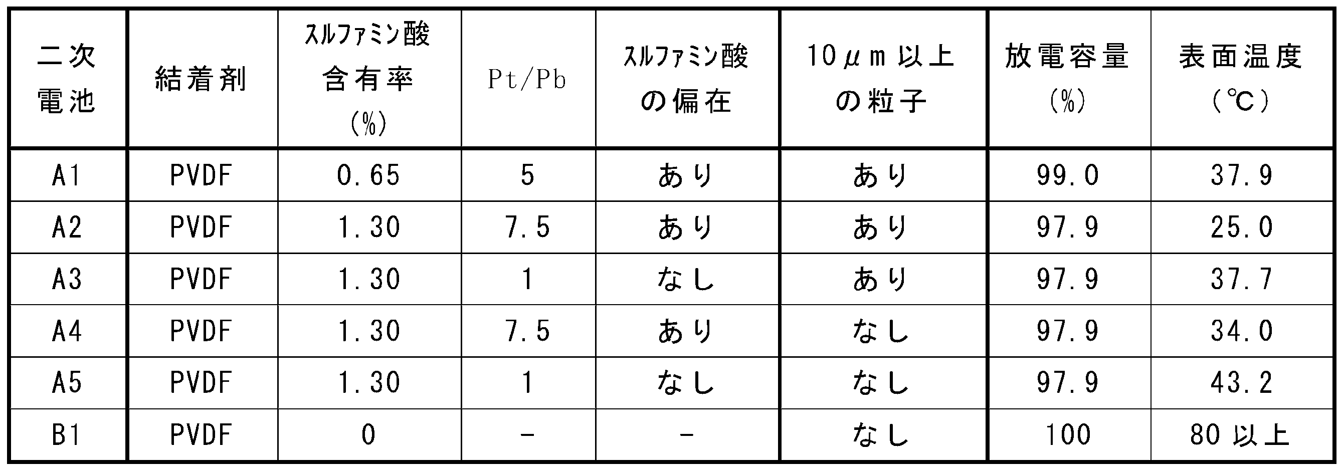
正極合剤に含まれるスルファミン酸(平均粒子径100μm)の含有率を1.30質量%に変更し、Pt/Pb=7.5を満たす正極活物質層を形成したこと以外、実施例1と同様に、二次電池A2を作製した。
正極活物質層におけるスルファミン酸の分布がPt/Pb<2(ここではP2t/P2b≒1)を満たすように乾燥温度を室温に制御したこと以外、実施例2と同様に、二次電池A3を作製した。
正極スラリーを調製する際、スルファミン酸を予めNMPに完全に溶解させたこと以外、実施例2と同様に、二次電池A4を作製した。具体的には、50℃のNMPに正極合剤の1.3質量%に相当する量のスルファミン酸を添加し、3時間かけて溶解させ、その後、活物質粒子と、アセチレンブラックと、ポリフッ化ビニリデン(PVDF)とを、95:2.5:2.5の質量比でスルファミン酸のNMP溶液に添加して、攪拌し、正極スラリーを調製し、Pt/Pb=7.5を満たす正極活物質層を形成した。
正極活物質層におけるスルファミン酸の分布がPt/Pb<2(ここではP2t/P2b≒1)を満たすように乾燥温度を室温に制御したこと以外、実施例4と同様に、二次電池A5を作製した。
正極合剤にスルファミン酸を含ませなかった(スルファミン酸の含有率は0%)こと以外、実施例1と同様に、二次電池B1を作製した。
実施例および比較例で得られた二次電池について、下記の評価を行った。
(1)放電容量
25℃の環境下で、電池を0.3Itの電流で電圧が4.2Vになるまで定電流充電し、その後、4.2Vの定電圧で電流が0.05Itになるまで定電圧充電した。次いで、0.3Itの定電流で電圧が2.5Vになるまで放電した。同様の充放電を2回繰り返し、2回目の放電容量を求めた。電池B1の放電容量を100%としたときの、電池A1~A5の放電容量を相対値(%)で表1に示す。
(a)25℃の環境下で、電池を0.3Itの定電で電圧が4.2Vになるまで定電流充電し、その後、4.2Vの定電圧で電流が0.05Itになるまで定電圧充電した。
(b)25℃の環境下で、(a)で充電した電池の中央部に、丸釘(直径2.7mm)の先端を接触させ、1mm/秒の速度で突き刺し、内部短絡による電池電圧降下(Δ50mV)を検出した直後に、丸釘の突き刺しを停止した。電池が短絡して1分後の電池の表面温度を測定した。電池A1~A5および電池B1の表面温度を表1に示す。
本発明を現時点での好ましい実施態様に関して説明したが、そのような開示を限定的に解釈してはならない。種々の変形および改変は、上記開示を読むことによって本発明に属する技術分野における当業者には間違いなく明らかになるであろう。したがって、添付の請求の範囲は、本発明の真の精神および範囲から逸脱することなく、すべての変形および改変を包含する、と解釈されるべきものである。
Claims (15)
- 正極集電体と、前記正極集電体に担持された正極活物質層と、を備え、
前記正極活物質層は、活物質粒子と、結着剤と、熱分解性添加剤と、を含み、
前記熱分解性添加剤は、スルファミン酸を含み、
前記結着剤は、フッ素樹脂および水素化ニトリルブタジエンゴムからなる群より選択される少なくとも1種を含む、二次電池用正極。 - 前記熱分解性添加剤の少なくとも一部が、前記正極活物質層中に10μm以上の粒子径を有する粒子として存在する、請求項1に記載の二次電池用正極。
- 前記正極活物質層の断面観察において、粒子径10μm以上の前記熱分解性添加剤の粒子が、前記正極活物質層の面方向における長さ300μm×正極活物質層の厚さで定義される矩形の観測視野に5個以上観測される、請求項2に記載の二次電池用正極。
- 前記正極活物質層に含まれる前記スルファミン酸の含有率が、0.1質量%以上5質量%以下である、請求項1または2に記載の二次電池用正極。
- 前記正極活物質層の断面を走査型電子顕微鏡および電子線マイクロアナライザーで分析するとき、前記スルファミン酸が存在する箇所の面積が、前記正極活物質層の面方向における長さ300μm×正極活物質層の厚さTで定義される矩形の観測視野において、0.5面積%以上27面積%以下である、請求項1~4のいずれか1項に記載の二次電池用正極。
- 前記熱分解性添加剤の1gあたりに50μg以上1000μg以下の硫酸成分が含まれている、請求項1~5のいずれか1項に記載の二次電池用正極。
- 前記熱分解性添加剤が、前記活物質粒子の表面の一部を被覆している、請求項1~6のいずれか1項に記載の二次電池用正極。
- 前記熱分解性添加剤が、正極活物質層の正極集電体側よりも最表面側に偏在している、請求項1~7のいずれか1項に記載の二次電池用正極。
- 前記正極活物質層の厚さをTとするとき、
前記正極活物質層の前記正極集電体の表面から0.5Tまでの領域に存在する前記熱分解性添加剤の存在確率Pbと、
前記正極活物質層の前記正極集電体の表面から0.5Tの位置から前記最表面までの領域に存在する前記熱分解性添加剤の存在確率Ptとは、2≦Pt/Pbを満たす、請求項8に記載の二次電池用正極。 - 前記活物質粒子は、リチウム含有遷移金属酸化物を含み、
リチウム含有遷移金属酸化物は、リチウムとNiとを含み、層状岩塩型の結晶構造を有するリチウムニッケル酸化物を含み、
前記リチウムニッケル酸化物に含まれるLi以外の金属元素に占めるNiの割合は50原子%以上である、請求項1~9のいずれか1項に記載の二次電池用正極。 - 前記リチウムニッケル酸化物は、
式:LiαNix1M1x2M2(1-x1-x2)O2+βで表され、
元素M1は、V、CoおよびMnからなる群より選択される少なくとも1種であり、
元素M2は、Mg、Al、Ca、Ti、Cu、ZnおよびNbからなる群より選択される少なくとも1種であり、
0.95≦α≦1.05、
-0.05≦β≦0.05、
0.5≦x1<1、
0≦x2≦0.5、
0<1-x1-x2≦0.5
を満たす、請求項10に記載の二次電池用正極。 - 請求項1~11のいずれか一項に記載の二次電池用正極、負極、リチウムイオン伝導性の電解質、および、前記正極と前記負極との間に介在するセパレータを備える、二次電池。
- 活物質粒子と、結着剤と、熱分解性添加剤と、分散媒と、を含む正極スラリーを調製する工程と、
正極集電体を準備する工程と、
前記正極集電体の表面に前記正極スラリーを塗布して塗膜を形成する工程と、
前記塗膜を乾燥して、未圧延層を形成する工程と、
前記未圧延層を圧延して、正極活物質層を形成する工程と、
を具備し、
前記熱分解性添加剤は、スルファミン酸を含み、
前記結着剤は、フッ素樹脂および水素化ニトリルブタジエンゴムからなる群より選択される少なくとも1種を含み、
前記分散媒は、有機溶媒を含む、二次電池用正極の製造方法。 - 前記熱分解性添加剤の少なくとも一部が、前記正極スラリーに10μm以上の粒子径を有する粒子として存在する、請求項13に記載の二次電池用正極の製造方法。
- 前記正極活物質層の厚さをTとするとき、
前記正極活物質層の前記正極集電体の表面から0.5Tまでの領域に存在する前記熱分解性添加剤の存在確率Pbと、
前記正極活物質層の前記正極集電体の表面から0.5Tの位置から最表面までの領域に存在する前記熱分解性添加剤の存在確率Ptとは、2≦Pt/Pbを満たす、請求項13または14に記載の二次電池用正極の製造方法。
Priority Applications (4)
| Application Number | Priority Date | Filing Date | Title |
|---|---|---|---|
| US18/721,356 US20250038196A1 (en) | 2021-12-23 | 2022-12-22 | Secondary battery positive electrode, production method therefor, and secondary battery |
| EP22911324.6A EP4456201A4 (en) | 2021-12-23 | 2022-12-22 | POSITIVE ELECTRODE OF SECONDARY BATTERY, PRODUCTION METHOD THEREOF AND SECONDARY BATTERY |
| JP2023569526A JPWO2023120622A1 (ja) | 2021-12-23 | 2022-12-22 | |
| CN202280084659.2A CN118435391A (zh) | 2021-12-23 | 2022-12-22 | 二次电池用正极和其制造方法、以及二次电池 |
Applications Claiming Priority (2)
| Application Number | Priority Date | Filing Date | Title |
|---|---|---|---|
| JP2021209448 | 2021-12-23 | ||
| JP2021-209448 | 2021-12-23 |
Publications (1)
| Publication Number | Publication Date |
|---|---|
| WO2023120622A1 true WO2023120622A1 (ja) | 2023-06-29 |
Family
ID=86902707
Family Applications (1)
| Application Number | Title | Priority Date | Filing Date |
|---|---|---|---|
| PCT/JP2022/047281 Ceased WO2023120622A1 (ja) | 2021-12-23 | 2022-12-22 | 二次電池用正極およびその製造方法、ならびに二次電池 |
Country Status (5)
| Country | Link |
|---|---|
| US (1) | US20250038196A1 (ja) |
| EP (1) | EP4456201A4 (ja) |
| JP (1) | JPWO2023120622A1 (ja) |
| CN (1) | CN118435391A (ja) |
| WO (1) | WO2023120622A1 (ja) |
Cited By (1)
| Publication number | Priority date | Publication date | Assignee | Title |
|---|---|---|---|---|
| WO2024070704A1 (ja) * | 2022-09-29 | 2024-04-04 | パナソニックIpマネジメント株式会社 | 非水電解質二次電池用の正極、それを用いた非水電解質二次電池、および、非水電解質二次電池の正極用の正極スラリー |
Families Citing this family (1)
| Publication number | Priority date | Publication date | Assignee | Title |
|---|---|---|---|---|
| CN118738285B (zh) * | 2024-08-29 | 2025-02-07 | 宁德时代新能源科技股份有限公司 | 锂离子电池、正极极片及用电装置 |
Citations (4)
| Publication number | Priority date | Publication date | Assignee | Title |
|---|---|---|---|---|
| JP2000315502A (ja) | 1999-04-30 | 2000-11-14 | Dowa Mining Co Ltd | 正極活物質と該正極活物質を用いたリチウム二次電池 |
| JP2013054968A (ja) * | 2011-09-05 | 2013-03-21 | Ntt Facilities Inc | リチウムイオン電池及びその製造方法 |
| WO2019021891A1 (ja) * | 2017-07-28 | 2019-01-31 | 日本ゼオン株式会社 | 電気化学素子用電極および電気化学素子、並びに電気化学素子用電極の製造方法 |
| JP2019075222A (ja) * | 2017-10-13 | 2019-05-16 | トヨタ自動車株式会社 | 正極板および非水電解質二次電池 |
Family Cites Families (1)
| Publication number | Priority date | Publication date | Assignee | Title |
|---|---|---|---|---|
| CN109326795B (zh) * | 2017-08-01 | 2021-05-14 | 湖南汇锋高新能源有限公司 | 一种正负电极及使用该正负电极的高能固态钒电池 |
-
2022
- 2022-12-22 US US18/721,356 patent/US20250038196A1/en active Pending
- 2022-12-22 WO PCT/JP2022/047281 patent/WO2023120622A1/ja not_active Ceased
- 2022-12-22 EP EP22911324.6A patent/EP4456201A4/en active Pending
- 2022-12-22 JP JP2023569526A patent/JPWO2023120622A1/ja active Pending
- 2022-12-22 CN CN202280084659.2A patent/CN118435391A/zh active Pending
Patent Citations (4)
| Publication number | Priority date | Publication date | Assignee | Title |
|---|---|---|---|---|
| JP2000315502A (ja) | 1999-04-30 | 2000-11-14 | Dowa Mining Co Ltd | 正極活物質と該正極活物質を用いたリチウム二次電池 |
| JP2013054968A (ja) * | 2011-09-05 | 2013-03-21 | Ntt Facilities Inc | リチウムイオン電池及びその製造方法 |
| WO2019021891A1 (ja) * | 2017-07-28 | 2019-01-31 | 日本ゼオン株式会社 | 電気化学素子用電極および電気化学素子、並びに電気化学素子用電極の製造方法 |
| JP2019075222A (ja) * | 2017-10-13 | 2019-05-16 | トヨタ自動車株式会社 | 正極板および非水電解質二次電池 |
Non-Patent Citations (1)
| Title |
|---|
| See also references of EP4456201A4 |
Cited By (1)
| Publication number | Priority date | Publication date | Assignee | Title |
|---|---|---|---|---|
| WO2024070704A1 (ja) * | 2022-09-29 | 2024-04-04 | パナソニックIpマネジメント株式会社 | 非水電解質二次電池用の正極、それを用いた非水電解質二次電池、および、非水電解質二次電池の正極用の正極スラリー |
Also Published As
| Publication number | Publication date |
|---|---|
| US20250038196A1 (en) | 2025-01-30 |
| JPWO2023120622A1 (ja) | 2023-06-29 |
| CN118435391A (zh) | 2024-08-02 |
| EP4456201A4 (en) | 2025-09-03 |
| EP4456201A1 (en) | 2024-10-30 |
Similar Documents
| Publication | Publication Date | Title |
|---|---|---|
| CN103004005B (zh) | 锂离子二次电池 | |
| US11588179B2 (en) | Method for producing non-aqueous electrolyte solution, non-aqueous electrolyte solution, and non-aqueous electrolyte secondary battery | |
| JP2009176599A (ja) | 非水電解質二次電池 | |
| WO2010131401A1 (ja) | リチウムイオン二次電池用電極及びリチウムイオン二次電池 | |
| US11201334B2 (en) | Nonaqueous electrolyte secondary battery positive electrode and nonaqueous electrolyte secondary battery | |
| JP6607388B2 (ja) | リチウムイオン二次電池用正極及びその製造方法 | |
| EP3425702B1 (en) | Positive electrode for lithium ion secondary batteries, and lithium ion secondary battery | |
| DE102019111559A1 (de) | Silizium-anodenmaterialien | |
| JP2018006331A (ja) | 非水電解質二次電池用負極材料及びその製造方法 | |
| WO2023120622A1 (ja) | 二次電池用正極およびその製造方法、ならびに二次電池 | |
| US20250054982A1 (en) | Secondary battery positive electrode, production method therefor, and secondary battery | |
| EP4456199A1 (en) | Positive electrode for secondary battery, method for manufacturing same, and secondary battery | |
| JP2017126488A (ja) | 非水電解液二次電池用非水電解液及び非水電解液二次電池 | |
| WO2024143017A1 (ja) | 非水電解質二次電池およびこれを用いる正極 | |
| WO2024143010A1 (ja) | 非水電解質二次電池およびこれを用いる正極 | |
| CN108028361B (zh) | 用于锂离子二次电池的正极以及锂离子二次电池 | |
| KR102207523B1 (ko) | 리튬 이차전지 | |
| JP2017183048A (ja) | 正極活物質、及びそれを用いた正極並びにリチウムイオン二次電池 | |
| JP2016139549A (ja) | リチウムイオン電池 | |
| JP2020194739A (ja) | リチウムイオン二次電池及びリチウムイオン二次電池の製造方法 | |
| JP6992580B2 (ja) | 活物質およびそれを用いたリチウムイオン二次電池 | |
| JP2026041000A (ja) | 非水電解質二次電池用電極および非水電解質二次電池 | |
| WO2024143016A1 (ja) | 非水電解質二次電池およびこれを用いる正極 | |
| WO2024143012A1 (ja) | 非水電解質二次電池およびこれを用いる正極 | |
| WO2024143008A1 (ja) | 非水電解質二次電池およびこれを用いる正極 |
Legal Events
| Date | Code | Title | Description |
|---|---|---|---|
| 121 | Ep: the epo has been informed by wipo that ep was designated in this application |
Ref document number: 22911324 Country of ref document: EP Kind code of ref document: A1 |
|
| ENP | Entry into the national phase |
Ref document number: 2023569526 Country of ref document: JP Kind code of ref document: A |
|
| WWE | Wipo information: entry into national phase |
Ref document number: 202447044674 Country of ref document: IN |
|
| WWE | Wipo information: entry into national phase |
Ref document number: 18721356 Country of ref document: US |
|
| WWE | Wipo information: entry into national phase |
Ref document number: 202280084659.2 Country of ref document: CN |
|
| NENP | Non-entry into the national phase |
Ref country code: DE |
|
| ENP | Entry into the national phase |
Ref document number: 2022911324 Country of ref document: EP Effective date: 20240723 |