WO2023120629A1 - 医療用検査装置 - Google Patents
医療用検査装置 Download PDFInfo
- Publication number
- WO2023120629A1 WO2023120629A1 PCT/JP2022/047308 JP2022047308W WO2023120629A1 WO 2023120629 A1 WO2023120629 A1 WO 2023120629A1 JP 2022047308 W JP2022047308 W JP 2022047308W WO 2023120629 A1 WO2023120629 A1 WO 2023120629A1
- Authority
- WO
- WIPO (PCT)
- Prior art keywords
- light
- irradiation
- slit
- button
- optical system
- Prior art date
- Legal status (The legal status is an assumption and is not a legal conclusion. Google has not performed a legal analysis and makes no representation as to the accuracy of the status listed.)
- Ceased
Links
Images


Classifications
-
- A—HUMAN NECESSITIES
- A61—MEDICAL OR VETERINARY SCIENCE; HYGIENE
- A61B—DIAGNOSIS; SURGERY; IDENTIFICATION
- A61B3/00—Apparatus for testing the eyes; Instruments for examining the eyes
- A61B3/10—Objective types, i.e. instruments for examining the eyes independent of the patients' perceptions or reactions
- A61B3/13—Ophthalmic microscopes
- A61B3/135—Slit-lamp microscopes
-
- A—HUMAN NECESSITIES
- A61—MEDICAL OR VETERINARY SCIENCE; HYGIENE
- A61B—DIAGNOSIS; SURGERY; IDENTIFICATION
- A61B3/00—Apparatus for testing the eyes; Instruments for examining the eyes
- A61B3/0008—Apparatus for testing the eyes; Instruments for examining the eyes provided with illuminating means
Definitions
- the present invention relates to a medical testing device for testing a subject.
- Patent Literature 1 discloses an inspection apparatus that can inspect the anterior segment of the eye by irradiating the eye of the subject with slit light while being held by an operator (user) with one hand.
- a conventional ophthalmologic examination apparatus such as that disclosed in Patent Document 1
- light emitted from a light source is passed through a slit to be converted into slit light, and the slit light is irradiated to the subject's eye.
- a slit behind the light source can be inserted/removed to switch between irradiation of slit light and irradiation of illumination light that illuminates a wide range of the eye to be inspected. Since it is desired that a hand-held inspection apparatus be small, it is preferable to achieve miniaturization by having one light source play two roles.
- the present invention has been made in view of the above problems, and an object of the present invention is to provide a medical examination apparatus capable of independently controlling and irradiating a plurality of irradiation lights while achieving miniaturization.
- a medical examination apparatus includes an observation optical system for observing a subject, a slit light generation section for generating slit light, a first light generation section for generating first light different from the slit light, and an illumination optical system having an exterior in which a slit light irradiation port for irradiating slit light and a first light irradiation port for irradiating said first light are formed at different positions; and a control unit for controlling said illumination optical system,
- the first light generating section has a first light source arranged at a position where the first light can be emitted from the first light irradiation port.
- the illumination optical system includes an irradiation tube for passing the slit light emitted from the slit light generation unit, reflecting it at an end, and irradiating the subject. and the first light source is mounted so as not to enter the slit light passage area between the slit light passage area inside the irradiation tube and the outer wall (exterior) of the irradiation tube.
- a substrate may be installed as the first light generator.
- the medical examination apparatus may be characterized in that the board is extended in the longitudinal direction of the irradiation tube to ensure an area required for circuit configuration.
- control section may control the irradiation of the slit light and the irradiation of the first light independently.
- the first light generation unit has a first diffusion plate, and irradiates the first light from the first light irradiation port through the first diffusion plate. It may be characterized by
- the first light irradiation port adjusts the illumination range of the first light so that the center of the field of view of the observation optical system substantially coincides with the center of the illumination range of the first light. It may be characterized by having a restrictive opening.
- the illumination optical system has a second light generation section that generates a second light different from the slit light and the first light
- the exterior of the illumination optical system includes the It may be characterized by having a second light irradiation port for irradiating the second light in the vicinity of the first light irradiation port.
- the medical examination apparatus includes a grip portion that can be held by a user with one hand, and the grip portion includes a slit light button for instructing start/stop of irradiation of the slit light, and the first light. and a second light button for instructing start/stop of irradiation of the second light, wherein the slit light button, the first light button, the The second light button may be arranged so as to be operable with the gripping hand of the user when the grip is gripped.
- the slit light button and the second light button are arranged so that they can be operated with different fingers when the grip is held by the user.
- the second light button may be arranged so as to be operable with the same finger.
- the second light generation unit has a second diffusion plate, and irradiates the second light from the second light irradiation port through the second diffusion plate. It may be characterized by
- control unit prohibits irradiation of the second light during irradiation of the slit light, and prohibits irradiation of the slit light during irradiation of the second light. It is good also as a feature to control so that.
- control unit may perform control to exclusively irradiate the first light and the second light.
- the second light irradiation opening adjusts the illumination range of the second light so that the center of the field of view of the observation optical system substantially coincides with the center of the illumination range of the second light. It may be characterized by having a restrictive opening.
- FIG. 1 is an external view showing an example of a configuration of a medical examination apparatus 100 corresponding to at least one embodiment of the present invention
- FIG. 1 is an external view showing an example of a configuration of a medical examination apparatus 100 corresponding to at least one embodiment of the present invention
- FIG. 1 is an external view showing an example of a configuration of a medical examination apparatus 100 corresponding to at least one embodiment of the present invention
- FIG. 1 is an external view when an operator holds a medical examination apparatus 100 corresponding to at least one embodiment of the present invention with one hand
- FIG. 1 is a perspective view showing an example of a configuration of an irradiation section 10 portion in a medical examination apparatus 100 corresponding to at least one embodiment of the present invention
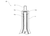
- FIG. 1 is a cross-sectional view showing an example of a configuration of an irradiation section 10 portion in a medical examination apparatus 100 corresponding to at least one embodiment of the present invention
- FIG. 1 is a cross-sectional view showing an example of a configuration of an irradiation section 10 portion in a medical examination apparatus 100 corresponding to at least one embodiment of the present invention
- FIG. 1 is a cross-sectional view showing an example of a configuration of an irradiation section 10 portion in a medical examination apparatus 100 corresponding to at least one embodiment of the present invention
- FIG. 1 is a cross-sectional view showing an example of a configuration of an irradiation section 10 portion in a medical examination apparatus 100 corresponding to at least one embodiment of the present invention
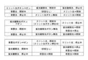
- FIG. FIG. 4 is an explanatory diagram showing an example of the relationship between the irradiation state of each irradiation light and the availability of button operation in the medical examination apparatus 100 corresponding to at least one embodiment of the present invention
- the medical examination apparatus is called a so-called slit lamp, and irradiates the eye of a subject (hereinafter referred to as "eye to be examined") as a subject with slit light, and scatters the light at the eye to be examined.
- eye to be examined a subject
- This is an apparatus for inspecting the cornea, lens, etc. of the eye to be inspected by observing the scattered light generated by the laser.
- the medical examination apparatus is a hand-held slit lamp will be described below.
- the medical examination apparatus 100 is an apparatus for examining an eye to be examined by operating it while holding it with one hand.
- the medical examination apparatus 100 includes an irradiation section 10, an observation section 20, a grip section 30, a finger hook section 40, an index finger side operation section 50, and a thumb side operation section 60. , a base portion 70 , an irradiation angle adjusting portion 80 , and a scale portion 90 .
- the irradiation unit 10 may be referred to as an illumination optical system
- the observation unit 20 may be referred to as an observation optical system.
- the irradiation unit (illumination optical system) 10 has a function of irradiating the subject's eye with irradiation light.
- the irradiating section 10 has a function of irradiating at least slit light as irradiation light onto the subject's eye, and may further have a function of irradiating spot light.
- the irradiation unit 10 includes, for example, an irradiation tube 11 , an irradiation port 12 , a disk operation unit 13 , a swing unit 14 and a separate light source installation unit 15 .
- the irradiation cylinder 11 has therein a known configuration for irradiating slit light, such as that described in Patent Document 1 mentioned above.
- the irradiation cylinder 11 includes a light source, a condenser lens, a spot disc, a slit disc, and a projection lens.
- light sources include LEDs.
- the irradiation tube 11 the light emitted from the light source is condensed by the condenser lens and then passed through the slit disk to generate slit light and spot light.
- the slit light and spot light enter the irradiation port 12 .
- the irradiation port 12 consists of a light projecting prism arranged inside. The slit light or spot light incident on the light projecting prism changes its direction and is irradiated in the direction of the subject's eye outside the apparatus.
- the disk operation unit 13 is a dial for the operator (user) to rotate the spot disk and the slit disk to select the length and width of the slit light to be irradiated and the diameter of the spot light.
- the swing part 14 is provided at one end portion and the lower part of the irradiation cylinder 11, and the other end portion positioned at a predetermined distance from the irradiation cylinder 11 is a plate-shaped member connected to an irradiation angle adjustment part 80 described later. Become.
- a marker for indicating the rotation angle of the irradiation section 10 is provided on a portion of the swing section 14 that contacts the outer periphery of the irradiation angle adjustment section 80 .
- the separate light source installation unit 15 is configured to install a light source different from the slit light, and is provided separately from the irradiation port 12 .
- a light source for background illumination first light source
- a light source for fluorescence observation illumination second light source
- a white LED is used as the background illumination light source
- a blue LED is used as the fluorescence observation illumination light source.
- the light source for background illumination and the light source for fluorescence observation illumination are examples of light sources provided in the separate light source installation section 15, and are not limited to these.
- the configuration is such that background illumination and fluorescence observation illumination light can be emitted when slit light or spot light is emitted.
- it can be used, for example, for photographing to explain to the subject how the slit light is irradiated (for example, photographing the anterior segment of the subject as the subject using background illumination). becomes.
- the irradiation range is not limited by the size of the slit turret, and the light is generated along the same optical path. It is possible to install the light source so that the background illumination and the fluorescence observation illumination are applied to a wider range compared to the conventional method.
- the separate light source installation section 15 is provided so that the light emitted from the irradiation port 12 and the light emitted from the separate light source installation section 15 are always directed in substantially the same direction. For example, the separate light source installation unit 15 rotates in the same manner as the irradiation port 12 rotates.
- the medical examination apparatus 100 can be easily handled. can be improved.
- the observation unit (observation optical system) 20 has a function of observing the subject's eye with the irradiation light emitted from the irradiation unit 10 .
- the observation unit 20 includes an observation housing 21 , a right-eye eyepiece 22 , a left-eye eyepiece 23 , and a zoom lever 24 .
- the observation housing 21, the right-eye eyepiece 22, and the left-eye eyepiece 23 are internally configured with the known observation optical system described in Patent Document 1 described above. Observation optical systems are divided into those for observation with the right eye and those for observation with the left eye.
- the observation optical system for the right eye is configured inside the observation housing 21 and the right eye eyepiece 22 .
- An optical system for left eye observation is configured inside the observation housing 21 and the left eye eyepiece 23 .
- the observation optical system consists of at least an objective lens, an eyepiece prism, a reticle lens, and an eyepiece lens.
- the slit light from the irradiation unit 10 is scattered by the subject's eye and enters the objective lens as scattered light.
- the incident scattered light passes through the eyepiece prism, reticle lens, and eyepiece lens and becomes light that can be observed by the operator.
- the variable power lever 24 is a lever that can change the observation magnification of the subject's eye by moving the objective lens in the front-rear direction by moving it in the left-right direction.
- the grip part 30 is provided so that the operator can hold it between the thumb of one hand and at least one of the four fingers on the index finger side (hereinafter also referred to as "index finger side fingers").
- the shape of the grip portion 30 is not particularly limited as long as it can be gripped by the operator, but a substantially cylindrical shape is preferable.
- the grip section 30 is attached to the lower portion of the observation housing 21 and has a curved cylindrical shape.
- the state in which the central axis of the grip portion 30 is oriented substantially vertically (vertical direction in FIGS. 1 to 3) will be referred to as the “reference state”. It is assumed that the direction of the central axis of the grip portion 30 shown in FIGS. 1 to 3 is substantially vertical. Accordingly, the conditions shown in FIGS. 1-3 are reference conditions.
- the finger hook part 40 is provided on the grip part 30 so as to be hooked on one of the fingers positioned on the index finger side when the operator grips the grip part 30 with one hand.
- the index finger side refers to a side of the grip portion 30 with which the index finger can come into contact when gripping the grip portion 30 .
- the finger positioned on the index finger side is at least one of the index finger, the middle finger, the ring finger and the little finger.
- the fact that the finger hooking portion 40 is caught on the finger means that the finger is in a state of receiving the load of the finger hooking portion 40 .
- the shape of the finger hook portion 40 is not particularly limited as long as it can be hooked on any one of the fingers positioned on the index finger side. In the examples shown in FIGS.
- the shape of the finger hook portion 40 is a shape projecting from the side surface of the grip portion 30 like a flange.
- the index finger side operation portion 50 is assumed to be a finger used for operation in advance among the fingers on the index finger side which are used for the operation of the examination and whose position is determined by the finger hook portion 40 when the operator grips the grip portion 30 with one hand. It is provided at a position within reach of a finger.
- the finger assumed in advance to be used for the operation is not particularly limited as long as it is one of the fingers on the index finger side, but a finger other than the finger on which the finger hook 40 is hooked is preferable. In this example, it is assumed that the index finger is used for operation. Further, the position within the reach of the finger means the position reached by moving the finger.
- the index finger side operation unit 50 is, for example, a button, a switch, or the like.
- the index finger side operation unit 50 is a switch that emits light from the light source arranged in the irradiation tube 11 of the irradiation unit 10 and emits light from the irradiation port 12 while being pressed.
- the index finger side operation portion 50 may be provided at a position within a reach of the finger for operation, assuming that the finger for operation is a finger closer to the thumb than the finger receiving the load from the finger hook portion 40 .
- the finger closer to the thumb than the load-bearing finger is, for example, the index finger if the load-bearing finger is the middle finger in the reference state.
- the thumb-side operation part 60 is used to operate the eye to be examined, and is provided at a position within the reach of the thumb whose position is determined by the finger hook part 40 when the operator grips the grip part 30 with one hand.
- the thumb-side operation section 60 may be provided with a plurality of operation points.
- the operation portion is provided with operation members such as buttons, various switches, and dials for inputting operations related to examination of the subject's eye.
- operation buttons 61 to 63 and an operation dial 64 are provided as operation members at the operation locations of the thumb-side operation unit 60 .
- the operation buttons 61 to 63 are assigned various functions related to inspection, such as on/off of background illumination and fluorescence observation illumination.
- the operation dial 64 is assigned a function of adjusting the amount of slit light emitted from the irradiation port 12 of the irradiation unit 10, for example.
- the operation positions of the plurality of operation buttons included in the thumb-side operation section 60 are particularly limited as long as they are within the reach of the thumb, the position of which is determined by the finger hook section 40 when the operator grips the grip section 30 with one hand. not. Examples of the shape, size, arrangement, etc. of the plurality of operation members included in the thumb-side operation section 60 will be described later.
- the base portion 70 is a plate-like member having one end portion attached to the lower portion of the grip portion 30 .
- the other end portion of the base portion 70 is provided with an irradiation angle adjusting portion 80 which will be described later.
- the irradiation angle adjustment unit 80 is a member that adjusts the irradiation angle of irradiation light by rotating the irradiation unit 10 with respect to the rotation axis.
- the irradiation angle adjusting section 80 is fixedly attached to the other end portion of the base section 70 .
- the irradiation angle adjusting section 80 is rotatably attached to a hole formed in the swing section 14 at a predetermined distance from the irradiation tube 11, and the upper surface thereof is exposed.
- the base portion 70 and the swing portion 14 are connected via the irradiation angle adjustment portion 80, and the swing portion 14 is rotatable with respect to the base portion 70 with the irradiation angle adjustment portion 80 as a reference.
- the irradiation angle adjustment unit 80 is configured by, for example, a bearing.
- the scale part 90 has a scale indicating the rotation angle on the upper surface of the rotating shaft. Specifically, the scale part 90 has a scale corresponding to the irradiation angle of the irradiation light emitted by the irradiation part 10 in an arc shape on the upper surface of the rotating shaft.
- the scale portion 90 is provided as a mark that indicates the rotation angle of the swing portion 14 with respect to the irradiation angle adjustment portion 80 in an arc shape on the upper surface of the irradiation angle adjustment portion 80 fitted in the swing portion 14 . Details of the scale portion 90 will be described later.
- the medical examination apparatus 100 when the medical examination apparatus 100 is divided into the thumb side and the index finger side by a reference plane parallel to the central axis and passing through the position of the finger hook 40, the center of gravity of the entire apparatus is on the index finger side. It may be a device configured with a load balance to position. With such a load balance, even if the hand grip of the grip portion 30 is loosened, the medical examination apparatus 100 tilts from the thumb side to the index finger side with the finger hook portion 40 as a reference. Since the inclination occurs with the finger hook 40 as a reference, the finger hook 40 is kept hooked on the finger in the reference state, for example. As a result, it is possible to more easily maintain the state of gripping the grip portion 30 even when the grip of the hand is loosened.
- FIG. 4 is an external view when an operator holds the medical examination apparatus 100 corresponding to at least one embodiment of the present invention with one hand.
- the grip part 30 is gripped between the thumb and forefinger of the operator's hand H.
- the grip part 30 is divided into an index finger side (front side in FIG. 4) where four fingers are located and a thumb side (back side in FIG. 4) where one thumb is located.
- the middle finger, the ring finger and the little finger are positioned in addition to the index finger.
- the finger hook part 40 is provided on the index finger side and is hooked on the middle finger of the hand H. That is, in FIG.
- the middle finger of the hand H is in a state of receiving the load of the finger hook portion 40 .
- the index finger of the hand H is in contact with the index finger side operation section 50 and is in a state where it can be operated.
- the thumb of the hand H is in contact with the thumb-side operating section 60 and is ready for operation.
- the plane passing through the dashed line A and dividing the thumb side and the index finger side into two is the above-described reference plane.
- the medical examination apparatus 100 of this example is an apparatus configured to have a load balance so that the center of gravity of the entire apparatus is located on the index finger side when the thumb side and the index finger side are divided by a reference plane.
- the medical inspection apparatus 100 in this example includes a separate light source installation unit 15 for installing a light source capable of irradiation control independently of the configuration for irradiating the slit light to the irradiation unit (illumination optical system) 10. and is characterized in that both functions of slit light irradiation and separate light source irradiation are realized in a compact configuration.
- the detailed configuration of the irradiation unit 10 in the medical examination apparatus 100 of this example will be described below with reference to FIGS. 5 to 9.
- first light a light source for background illumination
- second light a light source for fluorescence observation illumination
- 5 to 9 are a perspective view and a cross-sectional view showing an example of the configuration of the irradiation section 10 portion in the medical examination apparatus 100 corresponding to at least one embodiment of the present invention.
- the irradiation unit 10 in the medical inspection apparatus 100 of this example is a part of the configuration of a separate light source installation unit 15 at a location different from the irradiation port 12 for irradiating the slit light.
- a background illumination irradiation port (first light irradiation port) 15a and a fluorescence observation illumination irradiation port (second light irradiation port) 15b are provided.
- a background illumination irradiation port (first light irradiation port) 15a and a fluorescence observation illumination irradiation port (second light irradiation port) 15b are provided slightly below the irradiation port 12 provided at the tip of the irradiation barrel 11. is provided.
- a light source for background illumination ( A first light source) 15c and a fluorescence observation illumination light source (second light source) 15d are installed.
- the method of installing the background illumination light source (first light source) 15c and the fluorescence observation illumination light source (second light source) 15d is not particularly limited. It is conceivable that a substrate 15e on which a blue LED is mounted as the illumination light source (second light source) 15d is installed. By installing the substrate 15e along the inner wall of the irradiation cylinder 11, the background illumination light source (first light source ) 15c and a light source for fluorescence observation illumination (second light source) 15d. Regarding the installation of the substrate 15e, as shown in FIG.
- the substrate 15e may be extended in the longitudinal direction beyond the required area. This is because the substrate 15e must be arranged in a narrow space inside the irradiation tube 11, so if the substrate 15e is short and the wiring portion such as the harness is long, the harness may be pinched during assembly. Therefore, if there is a margin of space inside the irradiation cylinder 11, the length of the harness can be relatively shortened by extending the substrate 15e within that range. It is possible to reduce the risk of pinching and improve workability.
- the center of the visual field of the observation optical system substantially coincides with the center of the illumination range of the separate light source.
- the center of the visual field of the observation optical system means the center of the visual field range when looking into the observation section (observation optical system) 20 .
- the irradiation direction of the slit light is also configured to be directed toward the center of the field of view of the observation optical system. Any configuration may be used for substantially matching the center of the field of view of the observation optical system and the center of the illumination range of the separate light source.
- the background illumination irradiation port (first light irradiation port) 15a and the fluorescence observation illumination irradiation port (second light irradiation port) 15b are arranged so as to be apertures that limit the illumination range of the fluorescence observation illumination light source (second light source) 15d. It is conceivable to set the shape and size of the opening.
- diffuser plates for the background illumination irradiation port (first light irradiation port) 15a and the fluorescence observation illumination irradiation port (second light irradiation port) 15b as the first diffusion plate and the second diffusion plate, the It becomes possible to irradiate while diffusing the light of the first light source and the second light source.
- a different operation button from the index finger side operation unit 50 to which irradiation of the slit light is assigned is assigned.
- the operation button 61 is assigned as a button for switching light emission of the light source for background illumination (first light source) 15c
- an operation button 61 is assigned as a button for switching light emission of the light source for fluorescence observation illumination (second light source) 15d. It is conceivable to assign button 63 .
- a control unit (not shown) is provided for independently controlling irradiation of the slit light, the background illumination light, and the fluorescence observation illumination light. This makes it possible to independently execute irradiation control regardless of the state of other irradiation light.
- Slit light, background illumination light (hereinafter also referred to as “background light”), and fluorescence observation illumination light (hereinafter also referred to as “fluorescence observation light”) can be independently controlled by assigning operation buttons to each.
- background light background illumination light
- fluorescence observation illumination light hereinafter also referred to as “fluorescence observation light”
- the configuration is such that irradiation control can be executed independently regardless of the state of other irradiation light.
- the subject's eye will be irradiated with a plurality of irradiation lights at the same time, causing discomfort and stress to the subject.
- FIG. 10 is an explanatory diagram showing an example of the relationship between the irradiation state of each irradiation light and the possibility of button operation in the medical examination apparatus 100 corresponding to at least one embodiment of the present invention.
- a button for emitting slit light When the slit light is turned on, if the background light is off and the fluorescence observation light is off, or if the background light is on and the fluorescence observation light is off, irradiation of the slit light is permitted.
- the slit light when the slit light is turned on, if the background light is off and the fluorescence observation light is on, the irradiation of the slit light is prohibited, that is, the operation of the irradiation button for the slit light is disabled.
- the background light and the fluorescence observation light are exclusively controlled, a state in which both the background light and the fluorescence observation light are on cannot occur.
- the slit light is off and the background light is off when the fluorescence observation light is turned on, irradiation of the fluorescence observation light is permitted. If the slit light is off and the background light is off when the fluorescence observation light is turned on, irradiation of the fluorescence observation light is permitted. If the slit light is off and the background light is on when the fluorescence observation light is turned on, the illumination of the fluorescence observation light is permitted and the background light is stopped (for exclusive control).
- the slit light button index finger side operation part 50
- the background light button operation button 61
- the fluorescence observation light button operation button 63
- each button can be turned on and off at any time, so that the operation of the background light button and the fluorescence observation light button can be performed regardless of the illumination status of the background light and the fluorescence observation light. becomes valid.
- This makes it possible to operate the background light button and the fluorescence observation light button regardless of the illumination status of the background light and the fluorescence observation light, eliminating the troublesome operation of turning one off and then turning the other on. It is possible to obtain the effect of improving the convenience of the user.
- the observation optical system for observing the subject the slit light generation section for generating the slit light, the first light for generating the first light different from the slit light, and the a light generating unit
- an illumination optical system having an exterior in which a slit light irradiation port for irradiating slit light and a first light irradiation port for irradiating first light are formed at different positions
- a control unit for controlling the illumination optical system and the first light generation unit is arranged to have the first light source arranged at a position where the first light can be emitted from the first light irradiation port, so that the slit light irradiation port and the first light irradiation port are Configurations that can be formed at different locations and independently controlled can be realized.
- the illumination optical system includes an irradiation cylinder for passing the slit light emitted from the slit light generation unit and reflecting it at the end to irradiate the subject.
- the substrate on which the first light source is mounted is arranged as the first light generation unit so as not to enter the passage region of the slit light. Even if the first light generator that can be controlled independently of irradiation is provided, the size of the medical examination apparatus can be prevented from increasing and the size can be maintained.
- the substrate is arranged so as to secure the area necessary for the circuit configuration by extending it in the longitudinal direction of the irradiation cylinder, the limited space inside the irradiation cylinder is effectively utilized to install the first light generating section. can do.
- control unit independently controls the irradiation of the slit light and the irradiation of the first light, it becomes possible to realize operations that could not be performed conventionally, such as simultaneous irradiation of the slit light and the background light. .
- the first light generation unit has a first diffusion plate and is arranged to irradiate the first light from the first light irradiation port through the first diffusion plate, the first light is diffused by the first diffusion plate. Therefore, it is possible to use a light source with strong directivity, such as an LED, as the first light source.
- the first light irradiation port is arranged to have an aperture that limits the illumination range of the first light so that the center of the field of view of the observation optical system and the center of the illumination range of the first light substantially coincide with each other. It is possible to prevent a sense of discomfort due to the shift between the center of the visual field of the first light and the center of the illumination range of the first light.
- the illumination optical system has a second light generation unit that generates a second light different from the slit light and the first light, and the exterior of the illumination optical system irradiates the second light near the first light irradiation port. Since it is arranged so as to have the second light irradiation port, it is possible to selectively irradiate the first light or the second light as light different from the slit light.
- a grip portion that can be held by an operator with one hand.
- the grip portion includes a slit light button for instructing the start/stop of irradiation of the slit light, and a first light button for instructing the start/stop of irradiation of the first light. and a second light button for instructing start/stop of irradiation of the second light. Since it is arranged so as to be operable with the gripping hand, it is possible to perform operations related to irradiation of the slit light, the first light, and the second light with the hand gripping the grip.
- the slit light button and the second light button are arranged so that they can be operated with different fingers, and the first light button and the second light button can be operated with the same finger. Since they are arranged, it is possible to further reduce the possibility of erroneous operation by assigning different fingers to the combination of the slit light button and the second light button.
- the slit light button and the first light button are arranged so that they can be operated with different fingers, it is possible to reduce the possibility of erroneous operation by these buttons.
- the second light generation section has a second diffusion plate, and is arranged so that the second light is emitted from the second light irradiation port through the second diffusion plate, so that the second light is diffused by the second diffusion plate. Therefore, it is possible to use a light source with strong directivity, such as an LED, as the second light source.
- control unit since the control unit is set to prohibit the irradiation of the second light during the irradiation of the slit light, and to prohibit the irradiation of the slit light during the irradiation of the second light, the irradiation light is switched by an erroneous operation. Since the slit light and the second light are controlled so that irradiation of one of them cannot be started unless irradiation of the other is stopped, it is possible to prevent switching of the irradiation light due to an erroneous operation.
- control unit is set so as to exclusively irradiate the first light and the second light, simultaneous irradiation is prevented by exclusive control of the first light and the second light. It is possible to easily switch the irradiation light.
- the second light irradiation aperture is arranged to have an aperture that limits the illumination range of the second light so that the center of the field of view of the observation optical system and the center of the illumination range of the second light substantially match. It is possible to prevent a sense of discomfort due to the shift between the center of the visual field of the second light and the center of the illumination range of the second light.
Landscapes
- Life Sciences & Earth Sciences (AREA)
- Health & Medical Sciences (AREA)
- Medical Informatics (AREA)
- Molecular Biology (AREA)
- Ophthalmology & Optometry (AREA)
- Engineering & Computer Science (AREA)
- Biomedical Technology (AREA)
- Heart & Thoracic Surgery (AREA)
- Physics & Mathematics (AREA)
- Biophysics (AREA)
- Surgery (AREA)
- Animal Behavior & Ethology (AREA)
- General Health & Medical Sciences (AREA)
- Public Health (AREA)
- Veterinary Medicine (AREA)
- Eye Examination Apparatus (AREA)
- Endoscopes (AREA)
Abstract
Description
10 照射部
11 照射筒
12 照射口
13 円盤操作部
14 スイング部
15 別光源設置部
15a 背景照明照射口(第1光照射口)
15b 蛍光観察照明照射口(第2光照射口)
15c 背景照明用光源(第1光源)
15d 蛍光観察照明用光源(第2光源)
15e 基板
20 観察部
21 観察用筐体
22 右眼用観察部
23 左眼用観察部
24 変倍レバー
30 グリップ部
40 指掛部
50 人差し指側操作部
60 親指側操作部
61~63 操作用ボタン
64 操作用ダイヤル
70 ベース部
80 照射角度調整部
90 目盛部
Claims (13)
- 被検体を観察する観察光学系と、
スリット光を生成するスリット光生成部、スリット光とは異なる第1光を生成する第1光生成部、並びに、前記スリット光を照射するスリット光照射口と前記第1光を照射する第1光照射口を異なる位置に形成した外装、を有する照明光学系と、
前記照明光学系を制御する制御部と
を備え、
前記第1光生成部は、前記第1光照射口から前記第1光を照射可能な位置に配置された第1光源を有する
ことを特徴とする医療用検査装置。 - 前記照明光学系は、前記スリット光生成部から射出された前記スリット光を通過させて端部において反射させて前記被検体に照射するための照射筒を備えており、
前記照射筒の内側における前記スリット光の通過領域と前記照射筒の外壁(外装)との間において、前記スリット光の通過領域に侵入しないように、前記第1光源を搭載した基板を前記第1光生成部として設置する
ことを特徴とする請求項1に記載の医療用検査装置。 - 前記基板は、前記照射筒の長手方向に延伸させることで回路構成に必要な面積を確保する
ことを特徴とする請求項2に記載の医療用検査装置。 - 前記制御部は、前記スリット光の照射と前記第1光の照射とを独立に制御する
ことを特徴とする請求項1から請求項3の何れか一項に記載の医療用検査装置。 - 前記第1光生成部は、第1拡散板を有し、当該第1拡散板を介して前記第1光照射口から前記第1光を照射する
ことを特徴とする請求項1から請求項4の何れか一項に記載の医療用検査装置。 - 前記第1光照射口は、前記観察光学系の視野中心と前記第1光の照明範囲の中心が実質一致するよう前記第1光の照明範囲を制限する開口を持つ
ことを特徴とする請求項1から請求項5の何れか一項に記載の医療用検査装置。 - 前記照明光学系は、スリット光及び第1光と異なる第2光を生成する第2光生成部を有し、
前記照明光学系の外装は、前記第1光照射口の近傍に前記第2光を照射する第2光照射口を持つ
ことを特徴とする請求項1から請求項6の何れか一項に記載の医療用検査装置。 - ユーザが片手で把持可能なグリップ部を備え、
前記グリップ部は、
前記スリット光の照射の開始/停止を指示するスリット光ボタンと、
前記第1光の照射の開始/停止を指示する第1光ボタンと、
前記第2光の照射の開始/停止を指示する第2光ボタンと、
を有し、
前記スリット光ボタン、前記第1光ボタン、前記第2光ボタンは、ユーザが前記グリップ部を把持した状態において、当該把持した手で操作可能に配置されている
ことを特徴とする請求項7記載の医療用検査装置。 - ユーザが前記グリップ部を把持した状態において、
前記スリット光ボタンと前記第2光ボタンは、異なる指で操作可能に配置され、
前記第1光ボタンと前記第2光ボタンは、同一の指で操作可能に配置されている
ことを特徴とする請求項8に記載の医療用検査装置。 - 前記第2光生成部は、第2拡散板を有し、当該第2拡散板を介して前記第2光照射口から前記第2光を照射する
ことを特徴とする請求項7から請求項9の何れか一項に記載の医療用検査装置。 - 前記制御部は、前記スリット光の照射中は前記第2光の照射を禁止し、前記第2光の照射中は前記スリット光の照射を禁止するよう制御する
ことを特徴とする請求項7から請求項10の何れか一項に記載の医療用検査装置。 - 前記制御部は、前記第1光と前記第2光とを排他的に照射するよう制御する
ことを特徴とする請求項7から請求項11の何れか一項に記載の医療用検査装置。 - 前記第2光照射口は、前記観察光学系の視野中心と前記第2光の照明範囲の中心が実質一致するよう前記第2光の照明範囲を制限する開口を持つ
ことを特徴とする請求項7から請求項12の何れか一項に記載の医療用検査装置。
Priority Applications (4)
| Application Number | Priority Date | Filing Date | Title |
|---|---|---|---|
| US18/723,385 US20250057418A1 (en) | 2021-12-23 | 2022-12-22 | Medical examination device |
| EP22911331.1A EP4454543A4 (en) | 2021-12-23 | 2022-12-22 | MEDICAL EXAMINATION DEVICE |
| JP2023569528A JPWO2023120629A1 (ja) | 2021-12-23 | 2022-12-22 | |
| CN202280083796.4A CN118414116A (zh) | 2021-12-23 | 2022-12-22 | 医疗用检查装置 |
Applications Claiming Priority (2)
| Application Number | Priority Date | Filing Date | Title |
|---|---|---|---|
| JP2021-208955 | 2021-12-23 | ||
| JP2021208955 | 2021-12-23 |
Publications (1)
| Publication Number | Publication Date |
|---|---|
| WO2023120629A1 true WO2023120629A1 (ja) | 2023-06-29 |
Family
ID=86902718
Family Applications (1)
| Application Number | Title | Priority Date | Filing Date |
|---|---|---|---|
| PCT/JP2022/047308 Ceased WO2023120629A1 (ja) | 2021-12-23 | 2022-12-22 | 医療用検査装置 |
Country Status (6)
| Country | Link |
|---|---|
| US (1) | US20250057418A1 (ja) |
| EP (1) | EP4454543A4 (ja) |
| JP (1) | JPWO2023120629A1 (ja) |
| CN (1) | CN118414116A (ja) |
| TW (1) | TW202344217A (ja) |
| WO (1) | WO2023120629A1 (ja) |
Citations (6)
| Publication number | Priority date | Publication date | Assignee | Title |
|---|---|---|---|---|
| JP2005245539A (ja) * | 2004-03-01 | 2005-09-15 | Ima Kogaku Kikai Seisakusho:Kk | 照明装置、この照明装置を用いたスリットランプ、およびこの照明装置を用いた顕微鏡 |
| JP4136620B2 (ja) | 2002-11-21 | 2008-08-20 | 興和株式会社 | 眼科装置 |
| JP2012254197A (ja) * | 2011-06-09 | 2012-12-27 | Topcon Corp | 細隙灯顕微鏡装置 |
| JP2014147476A (ja) * | 2013-01-31 | 2014-08-21 | Takagi Seiko Corp | 細隙灯顕微鏡 |
| JP2020141998A (ja) * | 2019-03-08 | 2020-09-10 | 株式会社トプコン | 細隙灯顕微鏡 |
| US20210127967A1 (en) * | 2019-11-06 | 2021-05-06 | Lightx Innovations Inc. | Automated slit lamp system and method of examining an eye using same |
Family Cites Families (1)
| Publication number | Priority date | Publication date | Assignee | Title |
|---|---|---|---|---|
| CN116322476A (zh) * | 2020-10-28 | 2023-06-23 | 兴和株式会社 | 医疗用检查装置 |
-
2022
- 2022-12-22 TW TW111149328A patent/TW202344217A/zh unknown
- 2022-12-22 EP EP22911331.1A patent/EP4454543A4/en active Pending
- 2022-12-22 JP JP2023569528A patent/JPWO2023120629A1/ja active Pending
- 2022-12-22 US US18/723,385 patent/US20250057418A1/en active Pending
- 2022-12-22 CN CN202280083796.4A patent/CN118414116A/zh active Pending
- 2022-12-22 WO PCT/JP2022/047308 patent/WO2023120629A1/ja not_active Ceased
Patent Citations (6)
| Publication number | Priority date | Publication date | Assignee | Title |
|---|---|---|---|---|
| JP4136620B2 (ja) | 2002-11-21 | 2008-08-20 | 興和株式会社 | 眼科装置 |
| JP2005245539A (ja) * | 2004-03-01 | 2005-09-15 | Ima Kogaku Kikai Seisakusho:Kk | 照明装置、この照明装置を用いたスリットランプ、およびこの照明装置を用いた顕微鏡 |
| JP2012254197A (ja) * | 2011-06-09 | 2012-12-27 | Topcon Corp | 細隙灯顕微鏡装置 |
| JP2014147476A (ja) * | 2013-01-31 | 2014-08-21 | Takagi Seiko Corp | 細隙灯顕微鏡 |
| JP2020141998A (ja) * | 2019-03-08 | 2020-09-10 | 株式会社トプコン | 細隙灯顕微鏡 |
| US20210127967A1 (en) * | 2019-11-06 | 2021-05-06 | Lightx Innovations Inc. | Automated slit lamp system and method of examining an eye using same |
Non-Patent Citations (1)
| Title |
|---|
| See also references of EP4454543A4 |
Also Published As
| Publication number | Publication date |
|---|---|
| EP4454543A4 (en) | 2025-11-26 |
| CN118414116A (zh) | 2024-07-30 |
| JPWO2023120629A1 (ja) | 2023-06-29 |
| EP4454543A1 (en) | 2024-10-30 |
| US20250057418A1 (en) | 2025-02-20 |
| TW202344217A (zh) | 2023-11-16 |
Similar Documents
| Publication | Publication Date | Title |
|---|---|---|
| US4871245A (en) | Surgical microscope | |
| JPH09276232A (ja) | 眼底カメラ | |
| JP2001154103A (ja) | 光学器械の照明装置 | |
| JP2010243924A (ja) | 顕微鏡 | |
| WO2023120629A1 (ja) | 医療用検査装置 | |
| JP4579554B2 (ja) | 顕微鏡用照明装置 | |
| JP7764275B2 (ja) | 医療機器 | |
| JP2010176131A (ja) | 実体顕微鏡システム | |
| US20230320587A1 (en) | Medical examination device | |
| HK40108251A (zh) | 医疗用检查装置 | |
| JP3124676U (ja) | 細隙灯顕微鏡用補助照明装置 | |
| JP2012050570A (ja) | 光量制御装置、光量制御方法及びプログラム | |
| KR102421126B1 (ko) | 전동화 부품의 헤어핀 검사 장치 | |
| JP2005245539A (ja) | 照明装置、この照明装置を用いたスリットランプ、およびこの照明装置を用いた顕微鏡 | |
| JP2009122372A (ja) | 紫外線顕微鏡 | |
| JPH10314119A (ja) | 眼科装置 | |
| US7810927B2 (en) | Refractive treatment device with slit illumination | |
| JP2009039199A (ja) | 内視鏡装置 | |
| JP2023135596A (ja) | 医療機器 | |
| HK40099094A (en) | Medical examination device | |
| JP2012249700A (ja) | スリットランプ | |
| JP2013190760A (ja) | 顕微鏡用照明装置 | |
| US9510754B2 (en) | Illumination arrangement and surgical microscope incorporating the same | |
| JP2007021002A (ja) | 立体照明内視鏡システム | |
| JP2011013484A (ja) | 顕微鏡 |
Legal Events
| Date | Code | Title | Description |
|---|---|---|---|
| 121 | Ep: the epo has been informed by wipo that ep was designated in this application |
Ref document number: 22911331 Country of ref document: EP Kind code of ref document: A1 |
|
| WWE | Wipo information: entry into national phase |
Ref document number: 2023569528 Country of ref document: JP |
|
| WWE | Wipo information: entry into national phase |
Ref document number: 202280083796.4 Country of ref document: CN |
|
| WWE | Wipo information: entry into national phase |
Ref document number: 18723385 Country of ref document: US |
|
| NENP | Non-entry into the national phase |
Ref country code: DE |
|
| ENP | Entry into the national phase |
Ref document number: 2022911331 Country of ref document: EP Effective date: 20240723 |