WO2023127531A1 - 蓄電パック - Google Patents
蓄電パック Download PDFInfo
- Publication number
- WO2023127531A1 WO2023127531A1 PCT/JP2022/046262 JP2022046262W WO2023127531A1 WO 2023127531 A1 WO2023127531 A1 WO 2023127531A1 JP 2022046262 W JP2022046262 W JP 2022046262W WO 2023127531 A1 WO2023127531 A1 WO 2023127531A1
- Authority
- WO
- WIPO (PCT)
- Prior art keywords
- electricity storage
- housing
- pack
- spacer
- pack according
- Prior art date
- Legal status (The legal status is an assumption and is not a legal conclusion. Google has not performed a legal analysis and makes no representation as to the accuracy of the status listed.)
- Ceased
Links
Images





Classifications
-
- H—ELECTRICITY
- H01—ELECTRIC ELEMENTS
- H01M—PROCESSES OR MEANS, e.g. BATTERIES, FOR THE DIRECT CONVERSION OF CHEMICAL ENERGY INTO ELECTRICAL ENERGY
- H01M50/00—Constructional details or processes of manufacture of the non-active parts of electrochemical cells other than fuel cells, e.g. hybrid cells
- H01M50/20—Mountings; Secondary casings or frames; Racks, modules or packs; Suspension devices; Shock absorbers; Transport or carrying devices; Holders
- H01M50/204—Racks, modules or packs for multiple batteries or multiple cells
- H01M50/207—Racks, modules or packs for multiple batteries or multiple cells characterised by their shape
- H01M50/213—Racks, modules or packs for multiple batteries or multiple cells characterised by their shape adapted for cells having curved cross-section, e.g. round or elliptic
-
- H—ELECTRICITY
- H01—ELECTRIC ELEMENTS
- H01G—CAPACITORS; CAPACITORS, RECTIFIERS, DETECTORS, SWITCHING DEVICES, LIGHT-SENSITIVE OR TEMPERATURE-SENSITIVE DEVICES OF THE ELECTROLYTIC TYPE
- H01G11/00—Hybrid capacitors, i.e. capacitors having different positive and negative electrodes; Electric double-layer [EDL] capacitors; Processes for the manufacture thereof or of parts thereof
- H01G11/10—Multiple hybrid or EDL capacitors, e.g. arrays or modules
-
- H—ELECTRICITY
- H01—ELECTRIC ELEMENTS
- H01G—CAPACITORS; CAPACITORS, RECTIFIERS, DETECTORS, SWITCHING DEVICES, LIGHT-SENSITIVE OR TEMPERATURE-SENSITIVE DEVICES OF THE ELECTROLYTIC TYPE
- H01G11/00—Hybrid capacitors, i.e. capacitors having different positive and negative electrodes; Electric double-layer [EDL] capacitors; Processes for the manufacture thereof or of parts thereof
- H01G11/14—Arrangements or processes for adjusting or protecting hybrid or EDL capacitors
- H01G11/18—Arrangements or processes for adjusting or protecting hybrid or EDL capacitors against thermal overloads, e.g. heating, cooling or ventilating
-
- H—ELECTRICITY
- H01—ELECTRIC ELEMENTS
- H01G—CAPACITORS; CAPACITORS, RECTIFIERS, DETECTORS, SWITCHING DEVICES, LIGHT-SENSITIVE OR TEMPERATURE-SENSITIVE DEVICES OF THE ELECTROLYTIC TYPE
- H01G11/00—Hybrid capacitors, i.e. capacitors having different positive and negative electrodes; Electric double-layer [EDL] capacitors; Processes for the manufacture thereof or of parts thereof
- H01G11/78—Cases; Housings; Encapsulations; Mountings
- H01G11/82—Fixing or assembling a capacitive element in a housing, e.g. mounting electrodes, current collectors or terminals in containers or encapsulations
-
- H—ELECTRICITY
- H01—ELECTRIC ELEMENTS
- H01M—PROCESSES OR MEANS, e.g. BATTERIES, FOR THE DIRECT CONVERSION OF CHEMICAL ENERGY INTO ELECTRICAL ENERGY
- H01M50/00—Constructional details or processes of manufacture of the non-active parts of electrochemical cells other than fuel cells, e.g. hybrid cells
- H01M50/10—Primary casings; Jackets or wrappings
- H01M50/102—Primary casings; Jackets or wrappings characterised by their shape or physical structure
- H01M50/112—Monobloc comprising multiple compartments
-
- H—ELECTRICITY
- H01—ELECTRIC ELEMENTS
- H01M—PROCESSES OR MEANS, e.g. BATTERIES, FOR THE DIRECT CONVERSION OF CHEMICAL ENERGY INTO ELECTRICAL ENERGY
- H01M50/00—Constructional details or processes of manufacture of the non-active parts of electrochemical cells other than fuel cells, e.g. hybrid cells
- H01M50/20—Mountings; Secondary casings or frames; Racks, modules or packs; Suspension devices; Shock absorbers; Transport or carrying devices; Holders
- H01M50/262—Mountings; Secondary casings or frames; Racks, modules or packs; Suspension devices; Shock absorbers; Transport or carrying devices; Holders with fastening means, e.g. locks
-
- H—ELECTRICITY
- H01—ELECTRIC ELEMENTS
- H01M—PROCESSES OR MEANS, e.g. BATTERIES, FOR THE DIRECT CONVERSION OF CHEMICAL ENERGY INTO ELECTRICAL ENERGY
- H01M50/00—Constructional details or processes of manufacture of the non-active parts of electrochemical cells other than fuel cells, e.g. hybrid cells
- H01M50/20—Mountings; Secondary casings or frames; Racks, modules or packs; Suspension devices; Shock absorbers; Transport or carrying devices; Holders
- H01M50/262—Mountings; Secondary casings or frames; Racks, modules or packs; Suspension devices; Shock absorbers; Transport or carrying devices; Holders with fastening means, e.g. locks
- H01M50/264—Mountings; Secondary casings or frames; Racks, modules or packs; Suspension devices; Shock absorbers; Transport or carrying devices; Holders with fastening means, e.g. locks for cells or batteries, e.g. straps, tie rods or peripheral frames
-
- H—ELECTRICITY
- H01—ELECTRIC ELEMENTS
- H01M—PROCESSES OR MEANS, e.g. BATTERIES, FOR THE DIRECT CONVERSION OF CHEMICAL ENERGY INTO ELECTRICAL ENERGY
- H01M50/00—Constructional details or processes of manufacture of the non-active parts of electrochemical cells other than fuel cells, e.g. hybrid cells
- H01M50/20—Mountings; Secondary casings or frames; Racks, modules or packs; Suspension devices; Shock absorbers; Transport or carrying devices; Holders
- H01M50/271—Lids or covers for the racks or secondary casings
-
- H—ELECTRICITY
- H01—ELECTRIC ELEMENTS
- H01M—PROCESSES OR MEANS, e.g. BATTERIES, FOR THE DIRECT CONVERSION OF CHEMICAL ENERGY INTO ELECTRICAL ENERGY
- H01M50/00—Constructional details or processes of manufacture of the non-active parts of electrochemical cells other than fuel cells, e.g. hybrid cells
- H01M50/20—Mountings; Secondary casings or frames; Racks, modules or packs; Suspension devices; Shock absorbers; Transport or carrying devices; Holders
- H01M50/289—Mountings; Secondary casings or frames; Racks, modules or packs; Suspension devices; Shock absorbers; Transport or carrying devices; Holders characterised by spacing elements or positioning means within frames, racks or packs
-
- H—ELECTRICITY
- H01—ELECTRIC ELEMENTS
- H01M—PROCESSES OR MEANS, e.g. BATTERIES, FOR THE DIRECT CONVERSION OF CHEMICAL ENERGY INTO ELECTRICAL ENERGY
- H01M50/00—Constructional details or processes of manufacture of the non-active parts of electrochemical cells other than fuel cells, e.g. hybrid cells
- H01M50/20—Mountings; Secondary casings or frames; Racks, modules or packs; Suspension devices; Shock absorbers; Transport or carrying devices; Holders
- H01M50/289—Mountings; Secondary casings or frames; Racks, modules or packs; Suspension devices; Shock absorbers; Transport or carrying devices; Holders characterised by spacing elements or positioning means within frames, racks or packs
- H01M50/293—Mountings; Secondary casings or frames; Racks, modules or packs; Suspension devices; Shock absorbers; Transport or carrying devices; Holders characterised by spacing elements or positioning means within frames, racks or packs characterised by the material
-
- H—ELECTRICITY
- H01—ELECTRIC ELEMENTS
- H01M—PROCESSES OR MEANS, e.g. BATTERIES, FOR THE DIRECT CONVERSION OF CHEMICAL ENERGY INTO ELECTRICAL ENERGY
- H01M50/00—Constructional details or processes of manufacture of the non-active parts of electrochemical cells other than fuel cells, e.g. hybrid cells
- H01M50/30—Arrangements for facilitating escape of gases
-
- H—ELECTRICITY
- H01—ELECTRIC ELEMENTS
- H01M—PROCESSES OR MEANS, e.g. BATTERIES, FOR THE DIRECT CONVERSION OF CHEMICAL ENERGY INTO ELECTRICAL ENERGY
- H01M50/00—Constructional details or processes of manufacture of the non-active parts of electrochemical cells other than fuel cells, e.g. hybrid cells
- H01M50/30—Arrangements for facilitating escape of gases
- H01M50/317—Re-sealable arrangements
- H01M50/325—Re-sealable arrangements comprising deformable valve members, e.g. elastic or flexible valve members
-
- H—ELECTRICITY
- H01—ELECTRIC ELEMENTS
- H01M—PROCESSES OR MEANS, e.g. BATTERIES, FOR THE DIRECT CONVERSION OF CHEMICAL ENERGY INTO ELECTRICAL ENERGY
- H01M50/00—Constructional details or processes of manufacture of the non-active parts of electrochemical cells other than fuel cells, e.g. hybrid cells
- H01M50/40—Separators; Membranes; Diaphragms; Spacing elements inside cells
- H01M50/471—Spacing elements inside cells other than separators, membranes or diaphragms; Manufacturing processes thereof
- H01M50/477—Spacing elements inside cells other than separators, membranes or diaphragms; Manufacturing processes thereof characterised by their shape
-
- H—ELECTRICITY
- H01—ELECTRIC ELEMENTS
- H01G—CAPACITORS; CAPACITORS, RECTIFIERS, DETECTORS, SWITCHING DEVICES, LIGHT-SENSITIVE OR TEMPERATURE-SENSITIVE DEVICES OF THE ELECTROLYTIC TYPE
- H01G11/00—Hybrid capacitors, i.e. capacitors having different positive and negative electrodes; Electric double-layer [EDL] capacitors; Processes for the manufacture thereof or of parts thereof
- H01G11/78—Cases; Housings; Encapsulations; Mountings
-
- Y—GENERAL TAGGING OF NEW TECHNOLOGICAL DEVELOPMENTS; GENERAL TAGGING OF CROSS-SECTIONAL TECHNOLOGIES SPANNING OVER SEVERAL SECTIONS OF THE IPC; TECHNICAL SUBJECTS COVERED BY FORMER USPC CROSS-REFERENCE ART COLLECTIONS [XRACs] AND DIGESTS
- Y02—TECHNOLOGIES OR APPLICATIONS FOR MITIGATION OR ADAPTATION AGAINST CLIMATE CHANGE
- Y02E—REDUCTION OF GREENHOUSE GAS [GHG] EMISSIONS, RELATED TO ENERGY GENERATION, TRANSMISSION OR DISTRIBUTION
- Y02E60/00—Enabling technologies; Technologies with a potential or indirect contribution to GHG emissions mitigation
- Y02E60/10—Energy storage using batteries
Definitions
- the present disclosure relates to an electricity storage pack.
- the electricity storage pack is equipped with multiple electricity storage blocks. Further, each power storage block has a plurality of cells (unit cells) held by cell holders (for example, Patent Document 1). In the electricity storage pack disclosed in Patent Literature 1, the electricity storage blocks that are linearly connected are fixed to each other by penetrating screws that penetrate the respective cell holders.
- the electricity storage pack has a housing that accommodates a plurality of electricity storage blocks.
- the housing needs to be firmly fixed to the power storage block, but no specific configuration is disclosed.
- design changes such as increasing the strength of the cell holder more than necessary are required in order to improve the fixing strength between the housing and the storage block. .
- An object of the present disclosure is to provide an electricity storage pack that can firmly fix the housing and the electricity storage block.
- a power storage module is a power storage pack including at least one power storage block having a plurality of cells and a housing that houses the at least one power storage block, wherein the power storage block and the housing are , through one side of the housing and the at least one power storage block and fixed by a fixed shaft extending in the first direction.
- the housing and the electricity storage block can be firmly fixed.
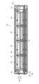
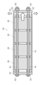
- FIG. 1 is a perspective view showing an electricity storage pack that is an example of an embodiment
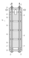
- FIG. FIG. 2 is a cross-sectional view taken along line AA of FIG. 1
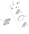
- 1 is an exploded perspective view of an electricity storage pack that is an example of an embodiment
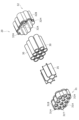
- FIG. FIG. 3 is a perspective view showing an exploded electricity storage block
- It is a perspective view which decompose
- It is a perspective view which explodes and shows a lid
- FIG. 4 is a schematic diagram showing an electricity storage pack that is another example of the embodiment
- FIG. 4 is a schematic diagram showing an electricity storage pack that is another example of the embodiment
- FIG. 4 is a schematic diagram showing an electricity storage pack that is another example of the embodiment
- FIG. 4 is a schematic diagram showing an electricity storage pack that is another example of the embodiment
- FIG. 4 is a schematic diagram showing an electricity storage pack that is another example of the embodiment
- FIG. 4 is a schematic diagram showing an electricity storage pack
- FIG. 1 An electricity storage pack 10 which is an example of an embodiment, will be described with reference to FIGS. 1 to 4.
- FIG. 1 An electricity storage pack 10, which is an example of an embodiment, will be described with reference to FIGS. 1 to 4.
- FIG. 1 An electricity storage pack 10, which is an example of an embodiment, will be described with reference to FIGS. 1 to 4.
- the power storage pack 10 is mainly attached to an electric vehicle and supplies electric power to a driving motor.
- the power storage pack 10 of the present disclosure is used, for example, as a power source for electric motorcycles, assisted bicycles, electric wheelchairs, electric tricycles, electric carts, and the like.
- the present disclosure does not specify the use of the electricity storage pack 10, and it can also be used as a power source for various electrical equipment used outdoors such as power tools.
- the housing 50 and at least one electricity storage block 20 can be firmly fixed, although the details will be described later. Moreover, according to the electricity storage pack 10 of the present disclosure, the number of parts can be reduced.
- the electricity storage pack 10 accommodates an electricity storage block 20 having a plurality of cells 30 , a circuit board 40 on which a protection circuit for controlling charging and discharging of the cells 30 is mounted, and the electricity storage block 20 . It includes a housing 50 and a fixed shaft 60 penetrating one side of the housing 50 and at least one power storage block 20 .
- the first direction which is at least the direction in which power storage blocks 20 are arranged and the direction in which fixed shaft 60 extends, will be described.
- the electricity storage pack 10 includes multiple electricity storage blocks 20 .
- the electricity storage pack 10 includes four electricity storage blocks 20 connected in series in the longitudinal direction, but is not limited to this embodiment.
- An inter-block member 21 is provided between the electricity storage blocks 20 .
- the inter-block members 21 have wall surfaces separating the electricity storage blocks 20 from each other, cushioning materials, and the like.
- the power storage block 20 is a unit in which a plurality of cells 30 are arranged in multiple stages. Moreover, in the electric storage block 20, the plurality of cells 30 are arranged such that the longitudinal direction of the cells 30 is parallel to the first direction.
- the electricity storage block 20 has a plurality of cells 30 , cell holders 31 and 32 that hold the cells 30 , and a filler 35 that fills the gaps between the plurality of cells 30 .
- ten cells 30 are arranged in three rows of three, four, and three cells (three parallel units, which will be described later) in a hexagonal lattice pattern.
- the power storage block 20 may be composed of multiple parallel units each having multiple cells 30 .
- the parallel unit may be configured by connecting both end surface electrodes of the cells 30 in parallel by lead plates.
- a parallel unit may have cells 30 arranged in a row.
- parallel units adjacent to each other may be arranged such that the polarities of the end surface electrodes of the cells 30 are opposite to each other.
- parallel units arranged adjacent to each other may be connected in series.
- the cell 30 is, for example, a cylindrical lithium-ion secondary battery and has electrodes on both ends as described above.
- the cell 30 is not limited to this embodiment, and may be another secondary battery such as a nickel-metal hydride battery, a nickel-cadmium battery, or a lithium polymer battery, or a power storage device such as a capacitor.
- the cell 30 is a cylindrical secondary battery, but is not limited to this embodiment and may be a prismatic secondary battery.
- the cell 30 includes a wound electrode group in which a positive electrode and a negative electrode are opposed to each other with a separator interposed therebetween; A sealing member that closes the opening at the other end may be provided.
- the sealing member may be electrically connected to one of the positive electrode and the negative electrode via a lead or the like.
- the can may be electrically connected to the other of the positive electrode and the negative electrode via a lead or the like.
- the cell 30 may have an exhaust at at least one end in the first direction. With this configuration, the gas accumulated in the cell 30 can be discharged to the outside of the cell 30 and the electricity storage block 20 through the exhaust portion.
- the exhaust portion may be an irreversible valve that opens by breaking a stamp, or a reversible valve that forms an exhaust path by further compressing a compressed elastic body with gas pressure. Further, exhaust portions may be formed at both ends of the cell 30 in the first direction.
- the cell holders 31 and 32 are divided into two at approximately the center of the cell 30 in the longitudinal direction.
- the cell holder 31 holds one side of a plurality of cells 30 arranged in a hexagonal lattice.
- the cell holder 31 includes a holding portion 31A integrally formed with a cylindrical storage portion into which one longitudinal end of the plurality of arranged cells 30 is fitted, and a holding portion 31A along the outer periphery of the plurality of arranged cells 30. It has a side wall 31B formed in the .
- the holding portion 31A of the cell holder 31 and the holding portion 32A of the cell holder 32 are each formed with a plurality of openings penetrating in the first direction (longitudinal direction of the cell 30). Current collection and evacuation of the cell 30 are performed through this opening.
- a side wall 31B of the cell holder 31 is provided with a hole 32H penetrating in the longitudinal direction.
- a fixed shaft 60 is inserted into the hole 32H and fitted with the spacer 21B of the inter-block member 21.
- Two holes 32 ⁇ /b>H are provided.
- the cell holder 31 may have an injection hole 31T into which the potting material is poured after the cells 30 are accommodated in the cell holders 31 and 32 and assembled.
- the cell holder 32 Since the cell holder 32 has the same configuration as the cell holder 31, the description thereof is omitted. An engaging portion formed at the other longitudinal end of the side wall 31B of the cell holder 31 is engaged with an engaging portion formed at one longitudinal end of the side wall 32B of the cell holder 32, thereby separating the cell holder 31 and the cell holder. 32 are connected.
- the filler 35 fills the gaps between the cells 30 arranged in the electricity storage block 20 .
- the filling material 35 is formed so as to fill the gaps between the cells 30 arranged in a hexagonal lattice as described above.
- the filler 35 is made of somewhat elastic material such as hard plastic or potting material, but is not limited to this embodiment.
- the filler 35 may contain an endothermic material such as aluminum hydroxide.
- the filler 35 is made of resin, it may be integrated with the cell holder 31 .
- the inter-block member 21 defines the interval between two adjacent electricity storage blocks 20 to form a gap between the two electricity storage blocks 20 .
- the inter-block member 21 is arranged along a plate-like cover 21A interposed between the two electricity storage blocks 20 and along the outer peripheral edge thereof, spacers 21B and 21D that couple with the cell holders 31 and 32 of the two electricity storage blocks 20, It has a spacer 21C interposed between the cover 21A and each cell holder 31, 32 in one direction.
- the cover 21A is arranged so that its thickness direction is parallel to the first direction, and covers the openings formed in the cell holders 31 and 32 .
- the cover 21 ⁇ /b>A can prevent the gas from reaching the adjacent power storage block 20 when the gas is discharged from the exhaust portion of the cell 30 through the opening. As a result, it is possible to prevent the cell holders 31 and 32 and the cells 30 of the adjacent electricity storage block 20 from being thermally damaged by the heat of the gas.
- a material having a high melting point is preferable for the material of the cover 21A. Examples include aluminum, copper, iron and stainless steel.
- the spacer 21B has a cylindrical shape extending in the first direction, and both ends in the first direction have hollow projections that fit and connect with the through holes 31H of the cell holder 31 and the through holes 31H of the cell holder 32 .
- a fixed shaft 60 is inserted into the hollow portion of the spacer 21B together with the through hole 31H.
- the spacer 21C is block-shaped and contacts the cover 21A on one end face in the first direction, and contacts the holding portions 31A and 32A of the cell holders 31 and 32 on the other end face.
- the spacer 21C may be arranged between adjacent openings among the plurality of openings in the holding portions 31A and 32A. Further, the spacer 21C may partially overlap the opening when viewed from the first direction.
- a plurality of spacers 21C in this embodiment are provided, and some of them are arranged between the first main surface of the cover 21A and one power storage block 20, and are arranged on the second main surface of the cover 21A (back side of the first main surface). and the other electricity storage block 20 .
- the spacer 21C may be fixed to the cover 21A with an adhesive or the like. Also, the spacer 21C may be mechanically locked to the cover 21A.
- the spacer 21D has a plate-like shape extending in the first direction, and has protrusions that fit into the cell holders 31 and 32 at both ends in the first direction.
- the cell holders 31, 32 are fitted with this projection.
- the end surface (principal surface) of the spacer 21D in the second direction perpendicular to the first direction may be a curved surface along the curve.
- the spacers 21B and 21D are arranged along the edge of the cover 21A (either the outer peripheral edge or the inner peripheral edge) and do not overlap the cover 21A when viewed from the first direction. With this configuration, the spacers 21B and 21D can preferentially restrict movement of the cover 21A in the second direction perpendicular to the first direction.
- the spacers 21B and 21D can also allow the cover 21A to move in the first direction.
- Spacers 21B and 21D have higher rigidity than spacer 21C.
- spacer 21C is softer or has a lower Young's modulus or elastic modulus than spacers 21B and 21D. Due to such a magnitude relationship in rigidity, when gas is discharged from the exhaust portion of the cell 30 to the cover 21A, the spacers 21C arranged on both main surfaces of the cover 21A are the first main spacers from which the gas is discharged. The spacer 21C on the side of the surface is pulled in the first direction, and the spacer 21C on the side of the second main surface, which is the back surface of the first main surface, is compressed in the first direction.
- the spacer 21C and the cover 21A can increase the distance in the first direction between the electricity storage block 20 having the cells 30 that eject gas from the exhaust portion and the cover 21A. As a result, the cover 21A is displaced in the first direction, the exhaust path around the electricity storage block 20 for releasing the gas is widened, and the exhaust to the outside of the electricity storage pack 10 can be facilitated.
- the spacers 21B and 21D may be made of electrically insulating hard plastic. For example, it may be polycarbonate.
- the spacer 21C may be made of an electrically insulating and elastic material.
- the spacer 21C may be, for example, chloroprene rubber or flame-retardant foamed resin. Further, the spacer 21 ⁇ /b>C may be arranged in a state of being compressed by receiving a force in the first direction when arranged between two adjacent power storage blocks 20 .
- the total dimension of at least one spacer 21C aligned in the first direction before disassembly is compared to the total dimension of at least one spacer 21C after disassembly. If the total size of one spacer 21C is large, it can be understood that the spacer 21C was arranged between the two power storage blocks 20 in a compressed state.
- At least one of the spacers 21B and 21D may be arranged through the through hole 31H instead of the outer periphery of the cover 21A. At this time, it is preferable that at least one of the spacers 21B and 21D does not overlap the inner peripheral edge of the through hole 31H when viewed from the first direction. Moreover, it is preferable that the spacers 21B and 21D surround the cover 21A in close proximity to the edge of the cover 21A. However, the spacers 21B and 21D do not necessarily have to abut the edges of the cover 21A. Also, in two adjacent electricity storage blocks 20, the exhaust part of the cell 30 may be directed toward one common inter-block member 21 side. This configuration can simplify the arrangement of the inter-block members 21 .
- the circuit board 40 mounts a protection circuit that controls charging and discharging of the cells 30 as described above. Also, the circuit board 40 mounts an electronic component that realizes a protection circuit.
- the circuit board 40 is configured in a plate shape extending along the longitudinal direction. In this way, since the circuit board 40 extending along the length direction connecting the cells 30 in series is arranged, the distance from the circuit board 40 to each cell 30 is short, and each cell for detecting an intermediate potential or the like is provided. Wiring up to the cell 30 can be facilitated.
- the protection circuit also has a circuit that detects the voltage of each cell 30 and cuts off the charging/discharging current. When the voltage of any cell 30 becomes lower than the minimum voltage, the protection circuit switches off the switching element that cuts off the discharge current to cut off the discharge current. Also, when the voltage of any cell 30 becomes higher than the maximum voltage, the switching element for stopping charging is turned off to stop charging. Thus, by detecting the voltage of each cell 30 and implementing a protection circuit that controls charging and discharging, the electricity storage pack 10 can be used safely while protecting the cell 30 .
- the circuit board 40 also mounts a temperature detection circuit that detects temperature abnormalities in the cells 30 .
- This temperature detection circuit detects an abnormal rise in the temperature of the cell 30 detected by the temperature sensor, and performs control such as executing current control for discharging and charging the cell 30, or stopping charging and discharging.
- the electricity storage pack 10 may have a current collecting member that electrically connects the electricity storage blocks 20 .
- the current collector plates are adjacent to each other.
- the housing 50 houses the power storage block 20 and protects the power storage block 20 .
- the housing 50 has a tubular main body 51 whose longitudinal direction is the first direction, and lids 52 and 53 that close both ends of the main body 51 in the longitudinal direction.
- the housing 50 may have a ring-shaped packing sandwiched between the opening of the main body 51 and the lids 52 and 53 to close the openings at both ends with a waterproof structure.
- the housing 50 has a pair of lids 52 and 53 that close the openings at both ends of the main body 51. The configuration may be such that the end face opening is closed only by the .
- the main body 51 is made of metal such as aluminum, and has strength and excellent heat dissipation.
- the main body 51 has a rectangular tubular shape, and is formed in a rectangular tubular shape with both ends opened.
- grooves or protrusions may be formed in the main body 51 along the longitudinal direction in order to improve strength.
- the surface of the main body 51 may be covered with a laminate film, vinyl, or the like.
- the lids 52 and 53 are made of hard plastic, they may be made of metal without being limited to this embodiment.
- the lids 52 and 53 are provided with holes 52H and 53H through which a fixed shaft 60 (to be described later) passes. Although two holes 52H and 53H are provided, they may be provided according to the number of fixed shafts 60 without being limited to this embodiment. Also, one of the lids 52 and 53 may be provided with a discharge connector for discharging from the cell 30 or a charge connector for charging the cell 30 .
- the lid 52 includes a frame body 52A having an exhaust port 52B, a plurality of porous bodies 52C closing the exhaust ports 52B, and between the porous bodies 52C and the electricity storage block 20 in the first direction.
- the frame 52A may be made of hard plastic or metal.
- the frame 52A is provided with a hole 52H through which the fixed shaft 60 passes and an insertion hole through which the screw 52F passes.
- Four insertion holes are formed because there are four screws 52F, but the number of insertion holes and screws 52F is not limited to this number.
- the porous body 52C may be, for example, a punching metal in which countless through-holes are formed in an aluminum plate.
- two porous bodies 52C are provided for frame 52A.
- the porous body 52 ⁇ /b>C can prevent the contents of the cells 30 from being released together with the gas to the outside of the electricity storage pack 10 .
- the heat of the gas is conducted to the porous body 52C, and the passing gas can be cooled.
- only one porous body 52C may be provided.
- the shield plate 52D is interposed in the first direction between the electricity storage block 20 closest to the lid 52 and the porous body 52C.
- the shielding plate 52D blocks the gas emitted from the cells 30 of the electricity storage block 20, and can suppress the direct blowing of the high-temperature gas to the porous body 52C.
- the shield plate 52D may be made of a material having a higher melting point than the porous body 52C. For example, it may be iron, stainless steel, or ceramics.
- the spacer 52E forms a gap between the porous body 52C and the shielding plate 52D, and by providing a gap between the spacers 52E, defines an exhaust path so that gas can enter this gap.
- the spacer 52E is cylindrical, and the screw 52F penetrates through the hollow portion of the spacer 52E.
- Four spacers 52E are also provided corresponding to the number of screws 52F. However, the number of spacers 52E is not limited to four.
- the screw 52F has a screw head at one end and is fastened with a nut 52G at the other end.
- Screw 52F and nut 52G may be hard plastic or metal.
- the lid 53 may also include a frame, a porous body, a shielding plate, a spacer, a screw, and a nut.
- the fixed shaft 60 is a shaft that penetrates the housing 50 and the four power storage blocks 20 and fastens and fixes the housing 50 and the four power storage blocks 20 along the longitudinal direction. be. More specifically, the fixed shaft 60 passes through the lids 52 and 53 of the housing 50 and through the cell holders 31 and 32 of the power storage block 20 . The fixed shaft 60 can firmly fix the housing 50 and the power storage block 20 . Also, the number of parts of the electricity storage pack 10 can be reduced.
- the fixed shaft 60 includes a rod 61 passing through the lids 52 and 53 of the housing 50 and the cell holders 31 and 32 of the four power storage blocks 20, and both ends of the rod 61 are fixed to the lids 52 and 53 of the housing 50. and a fixture 62 .
- the rod 61 is a metal shaft with threaded portions at both ends, and has a length that penetrates the housing 50 in the first direction.
- the fixture 62 is a nut and presses the end surfaces of the lids 52 and 53 .
- the fixed shaft 60 is not limited to the above configuration, and may have a rod made of a metal shaft and a fixture such as a push nut or an E-ring.
- the fixed shaft 60 is not limited to this embodiment, and may have a structure in which the power storage block 20 and the housing 50 are fixed by passing through at least one power storage block 20 and one of the lids 52. good. In the case of such a configuration, a separate fixing shaft for fixing the electricity storage blocks to each other and a fixing shaft for fixing the electricity storage block 20 and the lid 53 on the other side are required.
- the fixed shaft 60 may have a structure that passes through all the electricity storage blocks 20 and one lid 52 to fix the electricity storage blocks 20 and the housing 50 . In the case of such a configuration, a separate fixed shaft for fixing the electricity storage block 20 and the other lid 53 is required.
- the fixed shaft 60 may have a structure that penetrates at least one power storage block 20 and the main body 51 and fixes the power storage block 20 and the housing 50 without being limited to this embodiment.
- the electricity storage block 20 and the housing 50 are fixed by penetrating at least one electricity storage block 20 and one of the lids 52 to fix the electricity storage block 20 and the housing 50 together. It can be firmly fixed.
- the number of parts can be reduced compared to an electricity storage pack having a fixing shaft for fixing electricity storage blocks 20 to each other and a fixture for fixing electricity storage blocks 20 adjacent to lids 52 and 53 .
- FIGS. 7 to 10B An electricity storage pack 10 that is another example of the embodiment will be described with reference to FIGS. 7 to 10B.
- members that are different from those of the electricity storage pack 10 described above and added members are described with different reference numerals, and members that are the same as those of the electricity storage pack 10 described above are given the same reference numerals, and description thereof is omitted.
- the electricity storage pack 10 includes a fixed shaft 70 that extends in the axial direction when the pressure inside the housing 50 reaches or exceeds a predetermined pressure. More specifically, the fixed shaft 70 has a rod 71 that is plastically deformed in the axial direction when pulled with a predetermined pressure or more. The rod 71 may be formed with a diameter-reduced portion that is plastically deformed in the axial direction when pulled by a predetermined pressure or higher.
- the lids 52 and 53 of the housing 50 When the fixed shaft 70 extends in the axial direction, the main body 51 and the lids 52 and 53 are separated to form a gap between the main body 51 and the lids 52 and 53 to release the gas inside the housing 50 to the outside. can be made At this time, the lids 52 and 53 may have portions that fit inside the body 51 of the housing 50 . With this configuration, it is possible to regulate the displacement direction of the lids 52 and 53 when the rod 71 is deformed, and to seal the electricity storage pack 10 again after the gas release is completed.
- a spring washer 63 is provided between the fixture 62 of the fixed shaft 60 and the lids 52 and 53 .
- the spring washer 63 always urges the fixture 62 along the axial direction, and has a property of shrinking when a force acting against the urging force acts.
- the spring washer 63 may be a disc spring washer.
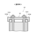
- the edge portion 52W of the lid 52 is formed to be thinner than the other portions.
- a groove-like thin portion 53X along the shape of the edge portion 53W of the frame 53A may be provided inside from the edge portion 53W.
- the lid 52 can be opened by displacing the edge portion 53W from the thin portion 53X as shown in FIG. 10B.
- a wall-like skirt extending toward the main body 51 may be provided around the edge 53W. This skirt stabilizes the arrangement of the lid 53 with respect to the main body 51 .
Landscapes
- Chemical & Material Sciences (AREA)
- Chemical Kinetics & Catalysis (AREA)
- Electrochemistry (AREA)
- General Chemical & Material Sciences (AREA)
- Engineering & Computer Science (AREA)
- Power Engineering (AREA)
- Microelectronics & Electronic Packaging (AREA)
- Battery Mounting, Suspending (AREA)
- Sealing Battery Cases Or Jackets (AREA)
Abstract
Description
図1から図4を用いて、実施形態の一例である蓄電パック10について説明する。
図2から図4に示すように、蓄電パック10は、複数の蓄電ブロック20を備えている。蓄電パック10は、長手方向に直列に連結された4つの蓄電ブロック20を備えているが、本実施形態に限定されることはない。蓄電ブロック20同士の間には、ブロック間部材21が設けられている。ブロック間部材21は、蓄電ブロック20同士を隔てる壁面、緩衝材等を有している。
図5に示すように、ブロック間部材21は隣り合う、2つの蓄電ブロック20の間隔を規定し、2つの蓄電ブロック20の間に隙間を形成する。ブロック間部材21は上記2つの蓄電ブロック20の間に介在する板状のカバー21Aと外周縁に沿って配置され、2つの蓄電ブロック20のセルホルダ31、32と結合するスペーサ21B、21Dと、第1方向においてカバー21Aと各セルホルダ31、32との間に介在するスペーサ21Cとを有する。
図1から図3に示すように、筐体50は、蓄電ブロック20を収容すると共に蓄電ブロック20を保護する。筐体50は、長手方向を第1方向としかつ筒状の本体51と、本体51の長手方向の両端部を閉塞する蓋52、53とを有している。筐体50は、本体51の開口部と蓋52、53との間にリング状のパッキンを挟着して、両端の開口部を防水構造で閉塞してもよい。また、筐体50は、本体51の両端の開口部を一対の蓋52、53で閉塞しているが、本体51が一方の端面のみを開口させた有底の筒状であって、蓋52のみで端面開口を閉塞する構成であってもよい。
図1から図3に示すように、固定軸60は、筐体50と4つの蓄電ブロック20とを貫通して筐体50と4つの蓄電ブロック20とを長手方向に沿って締結固定する軸である。より詳細には、固定軸60は、筐体50の蓋52、53を貫通し、蓄電ブロック20のセルホルダ31、32を貫通している。固定軸60によれば、筐体50と蓄電ブロック20とを強固に固定することができる。また、蓄電パック10の部品点数を削減することができる。
本開示の蓄電パック10によれば、少なくとも一つの蓄電ブロック20と、一方の蓋52とを貫通して蓄電ブロック20と筐体50とを固定することによって、蓄電ブロック20と筐体50とを強固に固定することができる。また、蓄電ブロック20同士を固定する固定軸と、蓋52、53と隣接する蓄電ブロック20とを固定する固定具とを有する蓄電パックと比較して部品点数を削減することができる。また、蓋52、53と隣接する蓄電ブロック20とを固定具によって蓄電ブロック20を貫通することなく固定する構成のように、特にセルホルダ31、32の強度を必要以上に上げる必要はない。
図7から図10Bを用いて、実施形態の他の一例である蓄電パック10について説明する。なお、以下では、上述した蓄電パック10と異なる部材、追加された部材について異なる符号として説明し、上述した蓄電パック10と同じ部材については、同じ符号として説明を省略する。
Claims (16)
- 複数のセルを有する少なくとも一つの蓄電ブロックと、少なくとも一つの前記蓄電ブロックを収容する筐体と、を備える蓄電パックであって、
少なくとも一つの前記蓄電ブロックと前記筐体とは、前記筐体の一側及び少なくとも一つの前記蓄電ブロックを貫通し第1方向に延びる固定軸によって固定されている、
蓄電パック。 - 請求項1に記載の蓄電パックであって、
前記第1方向において前記固定軸は、前記筐体の一側及び他側を貫通する、
蓄電パック。 - 請求項1又は2に記載の蓄電パックであって、
前記複数のセルは、セルホルダによって保持され、
前記固定軸は、前記セルホルダに設けられた挿通孔を貫通する、
蓄電パック。 - 請求項1に記載の蓄電パックであって、
少なくとも一つの前記蓄電ブロックは、複数の前記蓄電ブロックであって、
複数の前記蓄電ブロックは、前記第1方向に並ぶ、
蓄電パック。 - 請求項4に記載の蓄電パックであって、
複数の前記蓄電ブロックにはそれぞれ挿通孔を有し、
前記第1方向から見て、各挿通孔は互いに重なり、
前記各挿通孔を前記固定軸が貫通する、
蓄電パック。 - 請求項4又は5に記載の蓄電パックであって、
複数の前記蓄電ブロックのうち、前記第1方向において隣り合う2つの前記蓄電ブロックの間には、2つの前記蓄電ブロックの間に隙間を形成するブロック間部材が介在する、
蓄電パック。 - 請求項6に記載の蓄電パックであって、
前記ブロック間部材は、板状であるカバーと、前記カバーの縁に沿って配置されるとともに、2つの前記蓄電ブロックと連結する第1スペーサと、前記カバーと2つの前記蓄電ブロックとの間に介在する第2スペーサとを備える、
蓄電パック。 - 請求項7に記載の蓄電パックであって、
前記第1スペーサは前記第2スペーサより剛性が高く、
前記第1方向から見て、前記第1スペーサは前記カバーと重ならない、
蓄電パック。 - 請求項7又は8に記載の蓄電パックであって、
前記第2スペーサは圧縮された状態で前記カバーと前記蓄電ブロックの間に配置された、
蓄電パック。 - 請求項7から9のいずれか1項に記載の蓄電パックであって、
前記複数のセルは、セルホルダによって保持され、
前記セルホルダにおいて、前記複数のセルは、前記第1方向に対して垂直な第2方向に並ぶように配置され、
前記複数のセルは、前記第1方向の一端に排気部を備え、
前記排気部は前記第1方向において、前記カバーと向かい合う、
蓄電パック。 - 請求項1から10のいずれか1項に記載の蓄電パックであって、
前記筐体は、筒状の本体と、前記本体の両端部をそれぞれ塞ぐ蓋と、を有し、
前記固定軸は、前記蓋を貫通する、
蓄電パック。 - 請求項11に記載の蓄電パックであって、
前記蓋は、通気孔と、前記通気孔を塞ぐ多孔質体と、を含み、
前記第1方向において、前記多孔質体と前記蓄電ブロックの間には遮蔽板が介在する、
蓄電パック。 - 請求項12に記載の蓄電パックであって、
前記多孔質体と前記遮蔽板との間には、第3スペーサが配置され、
前記多孔質体と前記遮蔽板との間には、隙間が形成された、
蓄電パック。 - 請求項11から13のいずれか1項に記載の蓄電パックであって、
前記筐体の内部が所定圧力以上になった場合には、前記固定軸が軸方向に伸びることによって前記本体と前記蓋との間に隙間を生じさせる、
蓄電パック。 - 請求項11から13のいずれか1項に記載の蓄電パックであって、
前記固定軸と前記蓋とは、弾性部材を介して固定され、
前記筐体の内部が所定圧力以上になった場合には、前記弾性部材の付勢力に逆らって前記本体と前記蓋との間に隙間を生じさせる、
蓄電パック。 - 請求項11から13のいずれか1項に記載の蓄電パックであって、
前記蓋の前記固定軸が貫通する部分よりも外側の縁部は、前記蓋の他の部分よりも軸方向の厚みが小さく、
前記筐体の内部が所定圧力以上になった場合には、前記縁部が変形することによって前記本体と前記蓋との間に隙間を生じさせる、
蓄電パック。
Priority Applications (4)
| Application Number | Priority Date | Filing Date | Title |
|---|---|---|---|
| EP22915755.7A EP4459762A4 (en) | 2021-12-27 | 2022-12-15 | POWER STORAGE PACK |
| US18/722,244 US20250055103A1 (en) | 2021-12-27 | 2022-12-15 | Electricity storage pack |
| JP2023570844A JPWO2023127531A1 (ja) | 2021-12-27 | 2022-12-15 | |
| CN202280083774.8A CN118525414A (zh) | 2021-12-27 | 2022-12-15 | 蓄电组 |
Applications Claiming Priority (2)
| Application Number | Priority Date | Filing Date | Title |
|---|---|---|---|
| JP2021213403 | 2021-12-27 | ||
| JP2021-213403 | 2021-12-27 |
Publications (1)
| Publication Number | Publication Date |
|---|---|
| WO2023127531A1 true WO2023127531A1 (ja) | 2023-07-06 |
Family
ID=86998731
Family Applications (1)
| Application Number | Title | Priority Date | Filing Date |
|---|---|---|---|
| PCT/JP2022/046262 Ceased WO2023127531A1 (ja) | 2021-12-27 | 2022-12-15 | 蓄電パック |
Country Status (5)
| Country | Link |
|---|---|
| US (1) | US20250055103A1 (ja) |
| EP (1) | EP4459762A4 (ja) |
| JP (1) | JPWO2023127531A1 (ja) |
| CN (1) | CN118525414A (ja) |
| WO (1) | WO2023127531A1 (ja) |
Cited By (2)
| Publication number | Priority date | Publication date | Assignee | Title |
|---|---|---|---|---|
| DE102024209183A1 (de) * | 2024-09-24 | 2026-03-26 | Robert Bosch Gesellschaft mit beschränkter Haftung | Batterieanordnung für ein pedalgetriebenes Fahrzeug und pedalgetriebenes Fahrzeug mit Batterieanordnung |
| DE102024209185A1 (de) * | 2024-09-24 | 2026-03-26 | Robert Bosch Gesellschaft mit beschränkter Haftung | Batterieanordnung für ein pedalgetriebenes Fahrzeug und pedalgetriebenes Fahrzeug mit Batterieanordnung |
Citations (7)
| Publication number | Priority date | Publication date | Assignee | Title |
|---|---|---|---|---|
| JP2010033913A (ja) * | 2008-07-29 | 2010-02-12 | Sanyo Electric Co Ltd | 車両用電源装置の組電池 |
| US20120015218A1 (en) * | 2010-07-19 | 2012-01-19 | Hyun-Ye Lee | Battery module |
| JP2013218932A (ja) | 2012-04-10 | 2013-10-24 | Sanyo Electric Co Ltd | バッテリパック |
| WO2015001972A1 (ja) * | 2013-07-04 | 2015-01-08 | 株式会社 豊田自動織機 | 電池パック |
| JP2016507872A (ja) * | 2013-01-18 | 2016-03-10 | カヤゴ ゲーエムベーハーCayago Gmbh | 船艇用の再充電可能バッテリーユニット |
| CN206282904U (zh) * | 2016-12-15 | 2017-06-27 | 深圳市伟创源科技有限公司 | 锂电池及滑板车 |
| JP2020047451A (ja) * | 2018-09-19 | 2020-03-26 | 豊田合成株式会社 | 移動型電池パックシステム |
Family Cites Families (3)
| Publication number | Priority date | Publication date | Assignee | Title |
|---|---|---|---|---|
| JP5496746B2 (ja) * | 2010-03-31 | 2014-05-21 | 三洋電機株式会社 | バッテリパック |
| CN102110795B (zh) * | 2009-12-24 | 2015-03-04 | 三洋电机株式会社 | 电池组 |
| JP7079415B2 (ja) * | 2019-03-08 | 2022-06-02 | トヨタ自動車株式会社 | 組電池 |
-
2022
- 2022-12-15 WO PCT/JP2022/046262 patent/WO2023127531A1/ja not_active Ceased
- 2022-12-15 JP JP2023570844A patent/JPWO2023127531A1/ja active Pending
- 2022-12-15 US US18/722,244 patent/US20250055103A1/en active Pending
- 2022-12-15 EP EP22915755.7A patent/EP4459762A4/en active Pending
- 2022-12-15 CN CN202280083774.8A patent/CN118525414A/zh active Pending
Patent Citations (7)
| Publication number | Priority date | Publication date | Assignee | Title |
|---|---|---|---|---|
| JP2010033913A (ja) * | 2008-07-29 | 2010-02-12 | Sanyo Electric Co Ltd | 車両用電源装置の組電池 |
| US20120015218A1 (en) * | 2010-07-19 | 2012-01-19 | Hyun-Ye Lee | Battery module |
| JP2013218932A (ja) | 2012-04-10 | 2013-10-24 | Sanyo Electric Co Ltd | バッテリパック |
| JP2016507872A (ja) * | 2013-01-18 | 2016-03-10 | カヤゴ ゲーエムベーハーCayago Gmbh | 船艇用の再充電可能バッテリーユニット |
| WO2015001972A1 (ja) * | 2013-07-04 | 2015-01-08 | 株式会社 豊田自動織機 | 電池パック |
| CN206282904U (zh) * | 2016-12-15 | 2017-06-27 | 深圳市伟创源科技有限公司 | 锂电池及滑板车 |
| JP2020047451A (ja) * | 2018-09-19 | 2020-03-26 | 豊田合成株式会社 | 移動型電池パックシステム |
Cited By (2)
| Publication number | Priority date | Publication date | Assignee | Title |
|---|---|---|---|---|
| DE102024209183A1 (de) * | 2024-09-24 | 2026-03-26 | Robert Bosch Gesellschaft mit beschränkter Haftung | Batterieanordnung für ein pedalgetriebenes Fahrzeug und pedalgetriebenes Fahrzeug mit Batterieanordnung |
| DE102024209185A1 (de) * | 2024-09-24 | 2026-03-26 | Robert Bosch Gesellschaft mit beschränkter Haftung | Batterieanordnung für ein pedalgetriebenes Fahrzeug und pedalgetriebenes Fahrzeug mit Batterieanordnung |
Also Published As
| Publication number | Publication date |
|---|---|
| JPWO2023127531A1 (ja) | 2023-07-06 |
| EP4459762A1 (en) | 2024-11-06 |
| CN118525414A (zh) | 2024-08-20 |
| EP4459762A4 (en) | 2025-04-23 |
| US20250055103A1 (en) | 2025-02-13 |
Similar Documents
| Publication | Publication Date | Title |
|---|---|---|
| EP2654100B1 (en) | Battery pack | |
| US12355046B2 (en) | Battery module | |
| US11437664B2 (en) | Battery module | |
| CN109643778B (zh) | 电池模块 | |
| CN103038933B (zh) | 电池模块 | |
| JP6049288B2 (ja) | バッテリパック | |
| JP3169685U (ja) | 電池モジュール | |
| WO2014027783A1 (ko) | 벤팅 유도부를 포함하는 전지모듈 | |
| WO2016175591A1 (ko) | 배터리 팩 및 그 제조 방법 | |
| WO2013021573A1 (ja) | 電池ブロック及び該電池ブロックを有する電池モジュール | |
| WO2019045256A1 (ko) | 벤팅 유도 장치를 포함하는 파우치형 이차전지 | |
| JP2006216471A (ja) | パック電池 | |
| JPWO2020110447A1 (ja) | 電池モジュール | |
| EP4459762A1 (en) | Electricity storage pack | |
| CN118077090A (zh) | 电源装置及其制造方法 | |
| CN118613956A (zh) | 蓄电组 | |
| CA3118260A1 (en) | Battery cassette | |
| JP7815443B2 (ja) | バッテリーパック及びこれを含む車両 | |
| WO2024005034A1 (ja) | 蓄電モジュール | |
| JP2010086784A (ja) | 電池モジュール | |
| JP6974092B2 (ja) | 蓄電モジュール | |
| KR20240030988A (ko) | 배터리 팩 및 이를 포함하는 차량 | |
| JP7680118B2 (ja) | 耐衝撃性が向上した電池パック | |
| JP2006190611A (ja) | 電源装置 | |
| JP7804102B2 (ja) | バッテリーパック及びそれを含む車両 |
Legal Events
| Date | Code | Title | Description |
|---|---|---|---|
| 121 | Ep: the epo has been informed by wipo that ep was designated in this application |
Ref document number: 22915755 Country of ref document: EP Kind code of ref document: A1 |
|
| WWE | Wipo information: entry into national phase |
Ref document number: 2023570844 Country of ref document: JP |
|
| WWE | Wipo information: entry into national phase |
Ref document number: 202280083774.8 Country of ref document: CN |
|
| WWE | Wipo information: entry into national phase |
Ref document number: 18722244 Country of ref document: US |
|
| NENP | Non-entry into the national phase |
Ref country code: DE |
|
| ENP | Entry into the national phase |
Ref document number: 2022915755 Country of ref document: EP Effective date: 20240729 |