WO2023127540A1 - 車両用灯具 - Google Patents
車両用灯具 Download PDFInfo
- Publication number
- WO2023127540A1 WO2023127540A1 PCT/JP2022/046344 JP2022046344W WO2023127540A1 WO 2023127540 A1 WO2023127540 A1 WO 2023127540A1 JP 2022046344 W JP2022046344 W JP 2022046344W WO 2023127540 A1 WO2023127540 A1 WO 2023127540A1
- Authority
- WO
- WIPO (PCT)
- Prior art keywords
- lamp
- projection lens
- light
- light source
- pair
- Prior art date
- Legal status (The legal status is an assumption and is not a legal conclusion. Google has not performed a legal analysis and makes no representation as to the accuracy of the status listed.)
- Ceased
Links
Images




Classifications
-
- F—MECHANICAL ENGINEERING; LIGHTING; HEATING; WEAPONS; BLASTING
- F21—LIGHTING
- F21S—NON-PORTABLE LIGHTING DEVICES; SYSTEMS THEREOF; VEHICLE LIGHTING DEVICES SPECIALLY ADAPTED FOR VEHICLE EXTERIORS
- F21S41/00—Illuminating devices specially adapted for vehicle exteriors, e.g. headlamps
- F21S41/20—Illuminating devices specially adapted for vehicle exteriors, e.g. headlamps characterised by refractors, transparent cover plates, light guides or filters
- F21S41/25—Projection lenses
- F21S41/26—Elongated lenses
-
- F—MECHANICAL ENGINEERING; LIGHTING; HEATING; WEAPONS; BLASTING
- F21—LIGHTING
- F21S—NON-PORTABLE LIGHTING DEVICES; SYSTEMS THEREOF; VEHICLE LIGHTING DEVICES SPECIALLY ADAPTED FOR VEHICLE EXTERIORS
- F21S41/00—Illuminating devices specially adapted for vehicle exteriors, e.g. headlamps
- F21S41/10—Illuminating devices specially adapted for vehicle exteriors, e.g. headlamps characterised by the light source
- F21S41/14—Illuminating devices specially adapted for vehicle exteriors, e.g. headlamps characterised by the light source characterised by the type of light source
- F21S41/141—Light emitting diodes [LED]
- F21S41/143—Light emitting diodes [LED] the main emission direction of the LED being parallel to the optical axis of the illuminating device
-
- F—MECHANICAL ENGINEERING; LIGHTING; HEATING; WEAPONS; BLASTING
- F21—LIGHTING
- F21S—NON-PORTABLE LIGHTING DEVICES; SYSTEMS THEREOF; VEHICLE LIGHTING DEVICES SPECIALLY ADAPTED FOR VEHICLE EXTERIORS
- F21S41/00—Illuminating devices specially adapted for vehicle exteriors, e.g. headlamps
- F21S41/10—Illuminating devices specially adapted for vehicle exteriors, e.g. headlamps characterised by the light source
- F21S41/14—Illuminating devices specially adapted for vehicle exteriors, e.g. headlamps characterised by the light source characterised by the type of light source
- F21S41/141—Light emitting diodes [LED]
- F21S41/147—Light emitting diodes [LED] the main emission direction of the LED being angled to the optical axis of the illuminating device
-
- F—MECHANICAL ENGINEERING; LIGHTING; HEATING; WEAPONS; BLASTING
- F21—LIGHTING
- F21S—NON-PORTABLE LIGHTING DEVICES; SYSTEMS THEREOF; VEHICLE LIGHTING DEVICES SPECIALLY ADAPTED FOR VEHICLE EXTERIORS
- F21S41/00—Illuminating devices specially adapted for vehicle exteriors, e.g. headlamps
- F21S41/10—Illuminating devices specially adapted for vehicle exteriors, e.g. headlamps characterised by the light source
- F21S41/14—Illuminating devices specially adapted for vehicle exteriors, e.g. headlamps characterised by the light source characterised by the type of light source
- F21S41/141—Light emitting diodes [LED]
- F21S41/147—Light emitting diodes [LED] the main emission direction of the LED being angled to the optical axis of the illuminating device
- F21S41/148—Light emitting diodes [LED] the main emission direction of the LED being angled to the optical axis of the illuminating device the main emission direction of the LED being perpendicular to the optical axis
-
- F—MECHANICAL ENGINEERING; LIGHTING; HEATING; WEAPONS; BLASTING
- F21—LIGHTING
- F21S—NON-PORTABLE LIGHTING DEVICES; SYSTEMS THEREOF; VEHICLE LIGHTING DEVICES SPECIALLY ADAPTED FOR VEHICLE EXTERIORS
- F21S41/00—Illuminating devices specially adapted for vehicle exteriors, e.g. headlamps
- F21S41/20—Illuminating devices specially adapted for vehicle exteriors, e.g. headlamps characterised by refractors, transparent cover plates, light guides or filters
- F21S41/25—Projection lenses
- F21S41/255—Lenses with a front view of circular or truncated circular outline
-
- F—MECHANICAL ENGINEERING; LIGHTING; HEATING; WEAPONS; BLASTING
- F21—LIGHTING
- F21S—NON-PORTABLE LIGHTING DEVICES; SYSTEMS THEREOF; VEHICLE LIGHTING DEVICES SPECIALLY ADAPTED FOR VEHICLE EXTERIORS
- F21S41/00—Illuminating devices specially adapted for vehicle exteriors, e.g. headlamps
- F21S41/20—Illuminating devices specially adapted for vehicle exteriors, e.g. headlamps characterised by refractors, transparent cover plates, light guides or filters
- F21S41/25—Projection lenses
- F21S41/265—Composite lenses; Lenses with a patch-like shape
-
- F—MECHANICAL ENGINEERING; LIGHTING; HEATING; WEAPONS; BLASTING
- F21—LIGHTING
- F21S—NON-PORTABLE LIGHTING DEVICES; SYSTEMS THEREOF; VEHICLE LIGHTING DEVICES SPECIALLY ADAPTED FOR VEHICLE EXTERIORS
- F21S41/00—Illuminating devices specially adapted for vehicle exteriors, e.g. headlamps
- F21S41/20—Illuminating devices specially adapted for vehicle exteriors, e.g. headlamps characterised by refractors, transparent cover plates, light guides or filters
- F21S41/285—Refractors, transparent cover plates, light guides or filters not provided in groups F21S41/24 - F21S41/2805
-
- F—MECHANICAL ENGINEERING; LIGHTING; HEATING; WEAPONS; BLASTING
- F21—LIGHTING
- F21S—NON-PORTABLE LIGHTING DEVICES; SYSTEMS THEREOF; VEHICLE LIGHTING DEVICES SPECIALLY ADAPTED FOR VEHICLE EXTERIORS
- F21S41/00—Illuminating devices specially adapted for vehicle exteriors, e.g. headlamps
- F21S41/20—Illuminating devices specially adapted for vehicle exteriors, e.g. headlamps characterised by refractors, transparent cover plates, light guides or filters
- F21S41/29—Attachment thereof
- F21S41/295—Attachment thereof specially adapted to projection lenses
-
- F—MECHANICAL ENGINEERING; LIGHTING; HEATING; WEAPONS; BLASTING
- F21—LIGHTING
- F21S—NON-PORTABLE LIGHTING DEVICES; SYSTEMS THEREOF; VEHICLE LIGHTING DEVICES SPECIALLY ADAPTED FOR VEHICLE EXTERIORS
- F21S41/00—Illuminating devices specially adapted for vehicle exteriors, e.g. headlamps
- F21S41/30—Illuminating devices specially adapted for vehicle exteriors, e.g. headlamps characterised by reflectors
- F21S41/32—Optical layout thereof
-
- F—MECHANICAL ENGINEERING; LIGHTING; HEATING; WEAPONS; BLASTING
- F21—LIGHTING
- F21S—NON-PORTABLE LIGHTING DEVICES; SYSTEMS THEREOF; VEHICLE LIGHTING DEVICES SPECIALLY ADAPTED FOR VEHICLE EXTERIORS
- F21S41/00—Illuminating devices specially adapted for vehicle exteriors, e.g. headlamps
- F21S41/50—Illuminating devices specially adapted for vehicle exteriors, e.g. headlamps characterised by aesthetic components not otherwise provided for, e.g. decorative trim, partition walls or covers
-
- F—MECHANICAL ENGINEERING; LIGHTING; HEATING; WEAPONS; BLASTING
- F21—LIGHTING
- F21W—INDEXING SCHEME ASSOCIATED WITH SUBCLASSES F21K, F21L, F21S and F21V, RELATING TO USES OR APPLICATIONS OF LIGHTING DEVICES OR SYSTEMS
- F21W2102/00—Exterior vehicle lighting devices for illuminating purposes
- F21W2102/10—Arrangement or contour of the emitted light
- F21W2102/13—Arrangement or contour of the emitted light for high-beam region or low-beam region
-
- F—MECHANICAL ENGINEERING; LIGHTING; HEATING; WEAPONS; BLASTING
- F21—LIGHTING
- F21W—INDEXING SCHEME ASSOCIATED WITH SUBCLASSES F21K, F21L, F21S and F21V, RELATING TO USES OR APPLICATIONS OF LIGHTING DEVICES OR SYSTEMS
- F21W2102/00—Exterior vehicle lighting devices for illuminating purposes
- F21W2102/10—Arrangement or contour of the emitted light
- F21W2102/13—Arrangement or contour of the emitted light for high-beam region or low-beam region
- F21W2102/135—Arrangement or contour of the emitted light for high-beam region or low-beam region the light having cut-off lines, i.e. clear borderlines between emitted regions and dark regions
-
- F—MECHANICAL ENGINEERING; LIGHTING; HEATING; WEAPONS; BLASTING
- F21—LIGHTING
- F21Y—INDEXING SCHEME ASSOCIATED WITH SUBCLASSES F21K, F21L, F21S and F21V, RELATING TO THE FORM OR THE KIND OF THE LIGHT SOURCES OR OF THE COLOUR OF THE LIGHT EMITTED
- F21Y2115/00—Light-generating elements of semiconductor light sources
- F21Y2115/10—Light-emitting diodes [LED]
-
- F—MECHANICAL ENGINEERING; LIGHTING; HEATING; WEAPONS; BLASTING
- F21—LIGHTING
- F21Y—INDEXING SCHEME ASSOCIATED WITH SUBCLASSES F21K, F21L, F21S and F21V, RELATING TO THE FORM OR THE KIND OF THE LIGHT SOURCES OR OF THE COLOUR OF THE LIGHT EMITTED
- F21Y2115/00—Light-generating elements of semiconductor light sources
- F21Y2115/30—Semiconductor lasers
Definitions
- the present invention relates to a vehicle lamp equipped with a projection lens.
- Patent Document 1 describes, as a configuration of a projection lens in such a vehicle lamp, one in which the emission surface has a vertically elongated outer shape when viewed from the front of the lamp.
- the projection lens of the vehicular lamp described in "Patent Document 1" has a pair of left and right vertical wall surfaces extending rearward from both side edges of the emission surface of the lamp.
- Patent Document 1 By adopting the configuration described in "Patent Document 1" above, it is possible to realize a lamp design in which the projection lens looks narrow when viewed from the front of the lamp.
- the lateral width of the incident surface as well as the exit surface is narrow, so that the emitted light from the light source unit can be sufficiently taken into the projection lens. Moreover, it is not easy to ensure sufficient brightness of the light distribution pattern formed by the light emitted from the vehicle lamp.
- An object of the present invention is to provide a vehicular lamp capable of ensuring sufficient brightness.
- the present invention is intended to achieve the above object by devising the configuration of the projection lens.
- the vehicle lamp according to the present invention is A vehicular lamp configured to form a desired light distribution pattern by irradiating light emitted from a light source unit toward the front of the lamp via a projection lens
- the light source unit includes a light source and an optical member configured to cause the light emitted from the light source to enter the projection lens as light that converges in the lateral direction of the lamp
- the projection lens has an output surface having a vertically elongated outer shape when viewed from the front of the lamp, an incident surface formed to be wider than the output surface, and extending from both side edges of the output surface toward the rear of the lamp on both left and right sides. It is characterized by comprising a pair of left and right standing wall surfaces formed as follows.
- optical member is configured to allow the emitted light from the light source to enter the projection lens as light that converges in the left-right direction of the lamp. Part of the emitted light from the light source does not necessarily have to be directed in a direction of convergence, as long as the light is incident on the projection lens.
- the type of the above "light source” is not particularly limited, and for example, a light emitting element such as a light emitting diode or laser diode, or a light source bulb can be adopted.
- the specific surface shape and outer shape of the "output surface” are not particularly limited as long as they have a vertically long outer shape when viewed from the front of the lamp.
- the specific surface shape and outer shape of the "incident surface” are not particularly limited as long as they are wider than the output surface.
- the specific surface shape and outer shape of the above “vertical wall surface” are not particularly limited as long as they are formed so as to expand to the left and right sides toward the rear of the lamp from both side edges of the emission surface.
- a vehicle lamp according to the present invention is configured to irradiate light emitted from a light source unit toward the front of the lamp via a projection lens.
- Light converging in the left-right direction is incident on the projection lens.
- the projection lens has an emission surface that has a vertically elongated outer shape when viewed from the front of the lamp, an incidence surface that is wider than the emission surface, and an emission surface. Since a pair of left and right standing wall surfaces are formed so as to expand from both side edges of the surface toward the rear of the lamp, the following effects can be obtained.
- the projection lens since the projection lens has a vertically elongated outer shape when viewed from the front of the lamp, it is possible to achieve a lamp design in which the projection lens appears narrow when viewed from the front of the lamp.
- the projection lens is formed so that its entrance surface is wider than the exit surface, and is formed so as to extend from both side edges of the exit surface to the left and right sides toward the rear of the lamp. Therefore, the emitted light from the light source unit that reaches the projection lens as light that converges in the lateral direction of the lamp can be efficiently taken in from the entrance surface and guided to the exit surface. Therefore, it is possible to sufficiently ensure the brightness of the light distribution pattern formed by the light emitted from the vehicle lamp.
- the present invention as a vehicle lamp equipped with a projection lens, it is possible to realize a lamp design in which the projection lens appears narrow when viewed from the front of the lamp, and to ensure sufficient brightness of the light distribution pattern. can be done.
- the pair of left and right standing wall surfaces are configured such that the maximum distance between the rear edges is set to a value 1.5 times or more the maximum distance between the front edges. , the light emitted from the light source unit can be sufficiently taken into the projection lens.
- each of the pair of left and right standing wall surfaces is configured so that the angle of inclination with respect to the vertical plane extending in the front-rear direction of the lamp is set to a value within the range of 15 to 40°, the projection lens can It is possible to ensure a sufficient amount of light emitted from the incident light source unit and to efficiently guide the light that has entered from the incident surface to the exit surface.
- the projection lens can be seen to have a narrow width when viewed from the front of the lamp. can be easily realized.
- FIG. 1 is a side cross-sectional view showing a vehicle lamp according to an embodiment of the present invention
- FIG. 3 is a perspective view showing a low-beam light distribution pattern formed by light emitted from the vehicle lamp
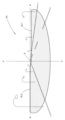
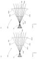
- (a) is a plane cross-sectional view showing a single projection lens of a vehicle lamp according to a first modification of the above embodiment
- (b) is a single projection lens of a vehicle lamp according to a second modification of the above embodiment.
- Flat cross-sectional view indicated by FIG. 4 is a view similar to FIG. 3, showing a third modification of the above embodiment
- FIG. 3 is a view similar to FIG. 2, showing a fourth modification of the above embodiment;
- FIG. 1 is a side sectional view showing a vehicle lamp 10 according to one embodiment of the present invention.
- 2 is a cross-sectional view taken along the line II-II of FIG. 1
- FIG. 3 is a view viewed in the direction of arrow III in FIG.
- the direction indicated by X is the "front of the lamp”
- the direction indicated by Y is the “left direction” ("right direction” when viewed from the front of the lamp) orthogonal to the "front of the lamp”
- the direction indicated by Z. is the "upward direction”. The same applies to figures other than these.
- the vehicle lamp 10 is a low-beam lamp unit incorporated as part of a headlamp, and is configured as a projector-type lamp unit.
- the vehicle lamp 10 includes a light source unit 20, a projection lens 30, and a base member 40 that supports them. to form a low-beam light distribution pattern (which will be described later).
- the projection lens 30 is a plano-convex aspherical lens having an optical axis Ax extending in the longitudinal direction of the lamp. is formed in a plane.
- the projection lens 30 projects the light source image formed on the rear focal plane, which is the focal plane including the rear focal point F, as an inverted image onto the virtual vertical screen in front of the lamp. A specific configuration of the projection lens 30 will be described later.
- the light source unit 20 includes a light emitting element 22 as a light source, and a reflector 24 as an optical member for causing the light emitted from the light emitting element 22 to enter the projection lens 30 as converging light in the lateral direction of the lamp.
- the light emitting element 22 is configured as a white light emitting diode having a horizontally long rectangular light emitting surface 22a.
- the light emitting element 22 is arranged on the rear side of the lamp with respect to the rear focal point F of the projection lens 30, and is mounted on the upper surface of the base member 40 with the light emitting surface 22a facing upward on the optical axis Ax. .
- the reflector 24 is supported on the upper surface of the base member 40 at its lower edge while being arranged to cover the light emitting element 22 from above.
- the reflecting surface 24a of the reflector 24 is composed of a substantially ellipsoidal curved surface with the center of light emission of the light emitting element 22 as the first focus, and the eccentricity thereof gradually increases from the vertical section to the horizontal section. is set. As a result, the reflector 24 converges the light from the light emitting element 22 on a point slightly forward of the rear focal point F in the vertical section, and moves the convergence position considerably forward in the horizontal section. It has become.
- the vehicle lamp 10 is arranged so that the optical axis Ax of the projection lens 30 extends downward by about 0.5 to 0.6° with respect to the longitudinal direction of the vehicle when it is incorporated in the headlamp. It has become.
- the base member 40 is a metal member provided with a plurality of heat radiation fins 40b, and functions as a heat sink that efficiently dissipates the heat generated by the light emitting element 24.
- An upward reflecting surface 40a is formed on the upper surface of the base member 40 for reflecting part of the reflected light from the reflector 24 upward toward the projection lens 30 in order to form a cutoff line of the light distribution pattern for low beam.
- the upward reflective surface 40a has a left area located on the left side of the optical axis Ax (right side when viewed from the front of the lamp) which is a horizontal plane including the optical axis Ax, and a right area located on the right side of the optical axis Ax. , a horizontal plane that is one step lower than the left region via a short slope.
- a front edge 40a1 of the upward reflecting surface 40a extends from the rear focal point F toward both left and right sides so as to curve forward.
- the output surface 30a of the projection lens 30 has an elongated outer shape when viewed from the front of the lamp. Specifically, both upper and lower edges of the emission surface 30a are formed so as to extend along an arc centered on the optical axis Ax when viewed from the front of the lamp, and both side edges thereof are vertical planes including the optical axis Ax (that is, vertical plane extending in the longitudinal direction of the lamp).
- the maximum vertical width H of the output surface 30a is set to a value that is twice or more (for example, about three times) the maximum horizontal width (a fixed width in this embodiment) W.
- the entrance surface 30b of the projection lens 30 is wider than its exit surface 30a.
- the projection lens 30 is provided with a pair of left and right upright wall surfaces 30c which are formed flat so as to expand from both side edges of the light output surface 30a toward the rear of the lamp.
- the projection lens 30 has an outer peripheral flange portion 30d formed so as to surround the upper and lower edges of the output surface 30a and the rear edges of the pair of left and right standing wall surfaces 30c when viewed from the front of the lamp.
- the outer peripheral flange portion 30d is formed with a constant width and a constant thickness, and its rear surface is flush with the incident surface 30b.
- the front edge 30c1 which is the line of intersection with the output surface 30a, is formed so as to extend parallel to the vertical plane including the optical axis Ax.
- the rear edge 30c2, which is a line, is formed to swell in an arc shape toward both left and right sides.
- the maximum distance D2 between the rear edges 30c2 of the pair of left and right standing walls 30c is 1.5 times or more the maximum distance D1 between the front edges 30c1. is set to a value of (for example, a value about twice as large).
- each of the pair of left and right standing wall surfaces 30c has an inclination angle ⁇ within the range of 15 to 40° (more preferably 20 to 30°) with respect to the vertical plane including the optical axis Ax (for example, 25°).
- the projection lens 30 is supported by the lens holder 32 at its outer peripheral flange portion 30d, and the lens holder 32 is supported by the base member 40.
- the lens holder 32 has an annular protrusion 32a formed on its front surface to surround the outer peripheral flange 30d of the projection lens 30, thereby supporting the projection lens 30 in a positioned state.
- a cover member 34 is arranged on the front side of the projection lens 30 to make substantially the entire area of the pair of left and right standing wall surfaces 30c invisible when viewed from the front of the lamp.
- the cover member 34 is an opaque resin member, and includes a pair of left and right side wall surfaces 34A formed to extend along the pair of left and right standing wall surfaces 30c, and rear ends of the pair of left and right side wall surfaces 34A. It has a pair of left and right vertical wall surfaces 30c and a base end portion 34B formed to surround the outer peripheral flange portion 30d.
- the pair of left and right side wall portions 34A are formed in a flat plate shape, and the inner side surfaces 34A1 at the front ends of the pair of left and right side wall portions 34A are aligned in the vertical plane parallel to the optical axis Ax in the vicinity of the left and right sides of the front edge 30c1 of the pair of left and right standing wall portions 30c. formed to extend along the
- the base end portion 34B is formed to extend in a flat plate shape along a vertical plane orthogonal to the optical axis Ax, and an annular flange portion 34B1 extending toward the rear of the lamp is formed on the outer peripheral edge portion.
- the inner peripheral surface of the annular flange portion 34B1 is engaged with the outer peripheral surface of the annular protrusion 32a of the lens holder 32, and the rear end surface of the annular flange portion 34B1 is in contact with the front surface of the lens holder 32.
- the cover member 34 is positioned with respect to the lens holder 32 .
- the projection lens 30 has the entrance surface 30b wider than the exit surface 30a, so the reflected light from the reflector 24 is taken into the projection lens 30 over a wide range.
- the pair of left and right standing wall surfaces 30c are formed so as to extend from both side edges of the light emitting surface 30a toward the rear of the lamp, and the reflected light from the reflector 24 converges in the left and right direction of the lamp.
- the light incident on the projection lens 30 from the incident surface 30b reaches the exit surface 30a without reaching the pair of left and right upright wall surfaces 30c.
- both the exit surface 30a and the entrance surface 30b are narrow in lateral width (that is, as indicated by the two-dot chain line in FIG.
- the emission surface 30a is formed so as to spread slightly toward the rear of the lamp from both side edges of the emission surface 30a
- the reflected light from the left and right end regions of the reflection surface 24a of the reflector 24 is reflected from the incident surface.
- the incident light from 30b is not taken into the projection lens 30, and enters the projection lens 30 through a pair of left and right vertical wall surfaces 30c' as indicated by the two-dot chain line in FIG. , the light is emitted as stray light (that is, light that does not contribute to the formation of the low-beam light distribution pattern) toward the front of the lamp.
- FIG. 4 is a view perspectively showing a low-beam light distribution pattern PL formed on a virtual vertical screen arranged at a position 25 m in front of the lamp by the light emitted from the vehicle lamp 10. As shown in FIG.
- the low-beam light distribution pattern PL is a left-handed low-beam light distribution pattern, and has cutoff lines CL1 and CL2 that are uneven on the left and right at the upper edge thereof.
- the cut-off lines CL1 and CL2 extend in the horizontal direction on the left and right sides of the line VV, which passes vertically through the vanishing point HV in the front direction of the lamp.
- the opposite lane side portion is formed as a lower cutoff line CL1
- the own lane side portion on the left side of the VV line is formed as an upper cutoff line CL2 rising from the lower cutoff line CL1 via an inclined portion. formed.
- the low-beam light distribution pattern PL is a light source image of the light emitting element 22 formed on the back focal plane of the projection lens 30 by the light from the light emitting element 22 reflected by the reflector 24, and projected onto the virtual vertical screen by the projection lens 30.
- the cutoff lines CL1 and CL2 are formed as inverted projection images of the front edge 40a1 of the upward reflecting surface 40a of the base member 40. As shown in FIG.
- the elbow point E which is the intersection of the lower cutoff line CL1 and the line VV, is located below HV by about 0.5 to 0.6°. This is because the optical axis Ax extends downward by about 0.5 to 0.6° with respect to the longitudinal direction of the vehicle.
- the vehicle lamp 10 is configured to irradiate the light emitted from the light source unit 20 toward the front of the lamp via the projection lens 30.
- the light emitting element 22 (light source ) is reflected by the reflector 24 (optical member) and is incident on the projection lens 30 as light that converges in the lateral direction of the lamp.
- an incident surface 30b formed with a wider width than this, and a pair of left and right standing wall surfaces 30c formed so as to expand from both side edges of the emitting surface 30a toward the rear of the lamp on both left and right sides.
- the projection lens 30 since the projection lens 30 has an output surface 30a that is vertically elongated when viewed from the front of the lamp, it is possible to achieve a lamp design in which the projection lens 30 appears narrow when viewed from the front of the lamp.
- the projection lens 30 has an entrance surface 30b wider than the exit surface 30a, and a pair of left and right upright wall surfaces 30c extending from both side edges of the exit surface 30a toward the rear of the lamp. Since it is formed to expand, the emitted light from the light source unit 20 reaching the projection lens 30 as light converging in the left-right direction of the lamp can be efficiently taken in from the incident surface 30b and guided to the emitting surface 30a. Therefore, the brightness of the low-beam light distribution pattern PL formed by the light emitted from the vehicle lamp 10 can be sufficiently ensured.
- the vehicular lamp 10 having the projection lens 30 realizes a lamp design in which the projection lens 30 appears narrow when viewed from the front of the lamp, and the brightness of the low-beam light distribution pattern PL is reduced. can be sufficiently ensured.
- the maximum distance D2 between the rear edges 30c2 of the pair of left and right standing wall surfaces 30c is set to a value that is 1.5 times or more the maximum distance D1 between the front edges 30c1. Since it is set, it becomes possible to easily capture the emitted light from the light source unit 20 sufficiently to the projection lens 30 .
- each of the pair of left and right upright wall surfaces 30c is set to a value within the range of 15 to 40 degrees with respect to the vertical plane extending in the longitudinal direction of the lamp. It is possible to ensure a sufficient amount of incident light emitted from the light source unit 20 and efficiently guide the light incident from the incident surface 30b to the emitting surface 30a.
- the maximum vertical width H of the output surface 30a is set to a value that is at least twice the maximum horizontal width W, so that the projection lens 30 can be designed to look narrow when viewed from the front of the lamp. Realization is easily possible.
- a cover member 34 is arranged on the front side of the lamp of the projection lens 30 to make substantially the entire area of the pair of left and right standing wall surfaces 30c invisible when viewed from the front of the lamp. It is possible to emphasize the lamp design in which the projection lens 30 looks narrow to the eye.
- the cover member 34 is configured so as to make substantially the entire area of the pair of left and right standing wall surfaces 30c invisible when viewed from the front of the lamp.
- the invisible range can be arbitrarily set in the configuration of the lamp.
- the vehicular lamp 10 is configured to form the low-beam light distribution pattern PL by its irradiation light. , a light distribution pattern for fog lamps, or a light distribution pattern formed additionally to the light distribution pattern for low beam when forming a light distribution pattern for high beam, etc.). is.
- FIG. 5(a) is a view similar to FIG. 2, showing the projection lens 130 of the vehicle lamp according to this modified example.
- the projection lens 130 of this modified example has an exit surface 130a and an entrance surface 130b similar to the projection lens 30 of the above-described embodiment. It is different from the above embodiment in that it extends to the incident surface 130b while maintaining the same shape as the pair of left and right vertical wall surfaces 130c in the projection lens 30 of the above embodiment.
- the front edges 130c1 of the pair of left and right standing wall surfaces 130c are positioned on the line of intersection with the output surface 130a, but the rear edges 130c2 are positioned on the line of intersection with the entrance surface 130b. .
- the projection lens 130 of this modified example has a portion (2 in FIG. 5A) that protrudes to both the left and right sides from the pair of left and right standing wall surfaces 130c in the outer peripheral flange portion 30d like the projection lens 30 of the above-described embodiment.
- the portion indicated by the dotted chain line) is not formed.
- the projection lens 130 of this modified example also has an entrance surface 130b wider than the exit surface 130a, and a pair of left and right standing wall surfaces 130c extending from both side edges of the exit surface 130a toward the rear of the lamp. Since it is formed so as to expand on both sides, as with the projection lens 30 of the above embodiment, the emitted light from the light source unit (not shown) reaching the projection lens 130 as light converging in the left-right direction of the lamp is projected onto the incident light. The light can be efficiently taken in from the surface 130b and guided to the exit surface 130a. Therefore, it is possible to obtain the same effects as in the case of the above embodiment.
- FIG. 5(b) is a view similar to FIG. 2, showing the projection lens 230 according to this modified example.
- the projection lens 230 of this modified example has an exit surface 230a, an entrance surface 230b, a pair of left and right upright wall surfaces 230c, and an outer peripheral flange portion 230d, like the projection lens 30 of the above-described embodiment.
- it is configured as a biconvex aspherical lens instead of a planoconvex aspherical lens like the projection lens 30 of the above embodiment.
- both the exit surface 230a and the entrance surface 230b are formed into convex surfaces, and the refractive power thereof is the same as that of the projection lens 30 of the above-described embodiment. is set. That is, light that reaches the projection lens 230 as light that converges in the lateral direction of the lamp from a light source unit (not shown) travels in a direction closer to the optical axis Ax than in the above embodiment from the incident surface 230b. The direction when the light is emitted from the emission surface 230a is the same as in the above embodiment.
- the light path of light reaching the projection lens 30 from the exit surface 30a and the entrance surface 30b of the projection lens 30 of the above embodiment and the light source unit is indicated by two-dot chain lines.
- the entrance surface 230b is wider than the exit surface 230a, and the pair of left and right standing wall surfaces 230c extend from both side edges of the exit surface 230a toward the rear of the lamp. Since it is formed so as to expand to both the left and right sides, the emitted light from the light source unit that reaches the projection lens 230 as light that converges in the left-right direction of the lamp, as in the projection lens 30 of the above-described embodiment, is projected from the incident surface 230b. It can be efficiently taken in and guided to the exit surface 230a. Therefore, it is possible to obtain the same effects as in the case of the above embodiment.
- the emitted light from the light source unit reaching the projection lens 230 travels in the direction closer to the optical axis Ax than in the case of the above embodiment within the projection lens 230. It is possible to increase the inclination angle of the upright wall surface 230c.
- FIG. 6 is a view similar to FIG. 3, showing a vehicle lamp 310 according to this modified example.
- the basic configuration of this modification is the same as that of the above embodiment, but the configuration of the projection lens 330 and the cover member 334 is different from that of the above embodiment.
- the projection lens 330 of this modified example is a plano-convex aspherical lens similar to the projection lens 30 of the above-described embodiment, and its emission surface 330a has a vertically elongated outer shape when viewed from the front of the lamp. Both side edges are formed so as to swell in an arc shape toward both left and right sides.
- the pair of left and right upright wall surfaces 330c has not only a rear end edge 330c2 but also a front end edge 330c1 formed in an arc shape, thereby forming a substantially conical surface shape.
- the pair of left and right upright wall surfaces 330c are set so that the maximum distance D2 between the rear edges 330c2 is 1.5 times or more the maximum distance D1 between the front edges 330c1.
- the maximum vertical width H of the exit surface 330a is set to be twice or more the maximum horizontal width W of the exit surface 330a.
- the projection lens 330 of this modification also has the same configuration of the incident surface 330b and the outer peripheral flange portion 330d as the projection lens 30 of the above-described embodiment.
- the cover member 334 of this modification includes a pair of left and right side wall surfaces 334A and a base end portion 334B. It is different from the case of morphology.
- the pair of left and right side wall surfaces 334A are formed to extend along the pair of left and right upright wall surfaces 330c of the projection lens 330, but are formed in a substantially conical shape. It extends in a plate-like shape along a substantially conical surface corresponding to the pair of left and right standing wall surfaces 330c.
- the inner side surfaces 334A1 of the front end portions of the pair of left and right side wall portions 334A are located near the left and right sides of the front edge 330c1 of the pair of left and right standing wall portions 330c. , extending in a direction that spreads toward the front of the lamp with respect to a vertical plane parallel to the optical axis Ax.
- the cover member 334 of this modified example also has a base end portion 334B having the same configuration as that of the above embodiment, and is positioned with respect to the lens holder 32 at its annular flange portion 334B1.
- the projection lens 330 has a vertically elongated outer shape when viewed from the front of the lamp.
- the design can be realized.
- the projection lens 330 of this modified example is formed so that both side edges of the exit surface 330a swell in an arc shape toward the left and right sides, the lamp gives a different impression from the case of the above-described embodiment. Design can be produced.
- the cover member 334 of this modified example is formed such that the inner side surfaces 334A1 at the front end portions of the pair of left and right side wall portions 334A extend in the direction of spreading toward the front of the lamp with respect to the vertical plane including the optical axis Ax. Therefore, in this respect as well, it is possible to produce a lamp design with a different impression from that of the above-described embodiment, and it is possible to improve moldability when manufacturing the cover member 334 .
- FIG. 7 is a view similar to FIG. 2 showing a vehicle lamp 410 according to this modified example.
- the basic configuration of this modification is the same as that of the above embodiment, but the configuration of the light source unit 420 is different from that of the above embodiment.
- the configuration is also partly different from that of the above embodiment.
- the light source unit 420 of this modified example includes a light emitting element 422 as a light source and a condenser lens 426 as an optical member. It is configured to be incident on the projection lens 30 as light to be projected.
- the condensing lens 426 is arranged on the optical axis Ax on the rear side of the lamp from the rear focal point F of the projection lens 30, and is supported by the base member 440 at its outer peripheral edge.
- the light-emitting element 422 is configured as a white light-emitting diode having a horizontally long rectangular light-emitting surface 422a, like the light-emitting element 22 of the above embodiment.
- the light emitting element 422 is arranged on the rear side of the lamp with respect to the condensing lens 426, with the light emitting surface 422a directed toward the front of the lamp on the optical axis Ax.
- the light emitting element 422 is mounted on a substrate 428 and supported by a base member 440 .
- the condensing lens 426 is configured to make the emitted light from the light emitting element 422 enter the projection lens 30 as convergent light to the same degree as the reflected light from the reflector 24 in the above embodiment with respect to the lateral direction of the lamp.
- the illumination light from the vehicle lamp 410 forms, for example, a high-beam light distribution pattern.
- the light source unit 420 is configured so that the light emitted from the light emitting element 422 is converged in the left-right direction of the lamp by the condenser lens 426 so as to enter the projection lens 30. Therefore, the light emitted from the light source unit 420 is efficiently taken in from the entrance surface 30b of the projection lens 30 having the oblong exit surface 30a and guided to the exit surface 230a.
- Reference Signs List 10 310, 410 Vehicle lamp 20, 420 Light source unit 22, 422 Light emitting element (light source) 22a, 422a light emitting surface 24 reflector (optical member) 24a Reflective surface 30, 130, 230, 330 Projection lens 30a, 130a, 230a, 330a Output surface 30b, 130b, 230b, 330b Incidence surface 30c, 130c, 230c, 330c Upright wall surface 30c1, 130c1, 330c1 Front edge 30c2, 130c 2, 330c2 rear edge 30d, 230d, 330d outer peripheral flange 32 lens holder 32a annular protrusion 34, 334 cover member 34A, 334A side wall surface 34A1, 334A1 inner surface 34B, 334B base end 34B1, 334B1 annular engaging portion 40, 440 Base member 40a Upward reflecting surface 40a1 Front edge 40b Radiation fin 426 Condensing lens (optical member) 428 Substrate Ax Optical axis
Landscapes
- Engineering & Computer Science (AREA)
- General Engineering & Computer Science (AREA)
- Physics & Mathematics (AREA)
- Microelectronics & Electronic Packaging (AREA)
- Optics & Photonics (AREA)
- Non-Portable Lighting Devices Or Systems Thereof (AREA)
Abstract
Description
光源ユニットからの出射光を投影レンズを介して灯具前方へ向けて照射することにより、所要の配光パターンを形成するように構成された車両用灯具において、
上記光源ユニットは、光源と、上記光源からの出射光を灯具左右方向に関して収束する光として上記投影レンズに入射させるように構成された光学部材とを備えており、
上記投影レンズは、灯具正面視において縦長の外形形状を有する出射面と、上記出射面よりも広幅で形成された入射面と、上記出射面の両側端縁から灯具後方へ向けて左右両側に拡がるように形成された左右1対の立壁面とを備えている、ことを特徴とするものである。
20、420 光源ユニット
22、422 発光素子(光源)
22a、422a 発光面
24 リフレクタ(光学部材)
24a 反射面
30、130、230、330 投影レンズ
30a、130a、230a、330a 出射面
30b、130b、230b、330b 入射面
30c、130c、230c、330c 立壁面
30c1、130c1、330c1 前端縁
30c2、130c2、330c2 後端縁
30d、230d、330d 外周フランジ部
32 レンズホルダ
32a 環状突起部
34、334 カバー部材
34A、334A 側壁面部
34A1、334A1 内側面
34B、334B 基端部
34B1、334B1 環状係合部
40、440 ベース部材
40a 上向き反射面
40a1 前端縁
40b 放熱フィン
426 集光レンズ(光学部材)
428 基板
Ax 光軸
CL1 下段カットオフライン
CL2 上段カットオフライン
D1、D2 最大間隔
E エルボ点
F 後側焦点
H 最大上下幅
PL ロービーム用配光パターン
W 最大左右幅
Claims (5)
- 光源ユニットからの出射光を投影レンズを介して灯具前方へ向けて照射することにより、所要の配光パターンを形成するように構成された車両用灯具において、
上記光源ユニットは、光源と、上記光源からの出射光を灯具左右方向に関して収束する光として上記投影レンズに入射させるように構成された光学部材とを備えており、
上記投影レンズは、灯具正面視において縦長の外形形状を有する出射面と、上記出射面よりも広幅で形成された入射面と、上記出射面の両側端縁から灯具後方へ向けて左右両側に拡がるように形成された左右1対の立壁面とを備えている、ことを特徴とする車両用灯具。 - 上記左右1対の立壁面は、後端縁相互間の最大間隔が前端縁相互間の最大間隔に対して1.5倍以上の値に設定されている、ことを特徴とする請求項1記載の車両用灯具。
- 上記左右1対の立壁面の各々は、灯具前後方向に延びる鉛直面に対する傾斜角が15~40°の範囲内の値に設定されている、ことを特徴とする請求項1または2記載の車両用灯具。
- 上記出射面は、最大上下幅が最大左右幅に対して2倍以上の値に設定されている、ことを特徴とする請求項1または2記載の車両用灯具。
- 上記投影レンズの灯具前方側に、灯具正面視において上記左右1対の立壁面の少なくとも一部を視認できなくするためのカバー部材が配置されている、ことを特徴とする請求項1または2記載の車両用灯具。
Priority Applications (3)
| Application Number | Priority Date | Filing Date | Title |
|---|---|---|---|
| EP22915764.9A EP4459179B1 (en) | 2021-12-28 | 2022-12-16 | Vehicle lamp |
| CN202280085845.8A CN118451277A (zh) | 2021-12-28 | 2022-12-16 | 车辆用灯具 |
| US18/723,946 US12535194B2 (en) | 2021-12-28 | 2022-12-16 | Vehicle lamp |
Applications Claiming Priority (2)
| Application Number | Priority Date | Filing Date | Title |
|---|---|---|---|
| JP2021-213991 | 2021-12-28 | ||
| JP2021213991A JP7606957B2 (ja) | 2021-12-28 | 2021-12-28 | 車両用灯具 |
Publications (1)
| Publication Number | Publication Date |
|---|---|
| WO2023127540A1 true WO2023127540A1 (ja) | 2023-07-06 |
Family
ID=86998859
Family Applications (1)
| Application Number | Title | Priority Date | Filing Date |
|---|---|---|---|
| PCT/JP2022/046344 Ceased WO2023127540A1 (ja) | 2021-12-28 | 2022-12-16 | 車両用灯具 |
Country Status (5)
| Country | Link |
|---|---|
| US (1) | US12535194B2 (ja) |
| EP (1) | EP4459179B1 (ja) |
| JP (1) | JP7606957B2 (ja) |
| CN (1) | CN118451277A (ja) |
| WO (1) | WO2023127540A1 (ja) |
Citations (4)
| Publication number | Priority date | Publication date | Assignee | Title |
|---|---|---|---|---|
| JP2015076374A (ja) * | 2013-10-11 | 2015-04-20 | 株式会社小糸製作所 | 車両用灯具 |
| JP2016015215A (ja) | 2014-07-01 | 2016-01-28 | 株式会社小糸製作所 | 車両用灯具 |
| JP2016085792A (ja) * | 2014-10-23 | 2016-05-19 | 市光工業株式会社 | 車両用灯具 |
| JP2020149877A (ja) * | 2019-03-14 | 2020-09-17 | 株式会社小糸製作所 | 灯具ユニットおよび車両用灯具 |
Family Cites Families (5)
| Publication number | Priority date | Publication date | Assignee | Title |
|---|---|---|---|---|
| JP4205048B2 (ja) * | 2004-02-26 | 2009-01-07 | 株式会社小糸製作所 | 車両用前照灯 |
| FR3009367B1 (fr) * | 2013-08-05 | 2018-06-15 | Valeo Vision | Dispositif optique et systeme de signalisation et/ou d'eclairage |
| US9587794B2 (en) * | 2014-05-21 | 2017-03-07 | Ford Global Technologies, Llc | Headlamp assembly with multiple high aspect ratio lenses |
| CN108591961B (zh) * | 2014-12-25 | 2021-01-26 | 株式会社小糸制作所 | 照明装置 |
| KR20210128244A (ko) * | 2020-04-16 | 2021-10-26 | 현대모비스 주식회사 | 자동차용 램프 및 그 램프를 포함하는 자동차 |
-
2021
- 2021-12-28 JP JP2021213991A patent/JP7606957B2/ja active Active
-
2022
- 2022-12-16 US US18/723,946 patent/US12535194B2/en active Active
- 2022-12-16 WO PCT/JP2022/046344 patent/WO2023127540A1/ja not_active Ceased
- 2022-12-16 EP EP22915764.9A patent/EP4459179B1/en active Active
- 2022-12-16 CN CN202280085845.8A patent/CN118451277A/zh active Pending
Patent Citations (4)
| Publication number | Priority date | Publication date | Assignee | Title |
|---|---|---|---|---|
| JP2015076374A (ja) * | 2013-10-11 | 2015-04-20 | 株式会社小糸製作所 | 車両用灯具 |
| JP2016015215A (ja) | 2014-07-01 | 2016-01-28 | 株式会社小糸製作所 | 車両用灯具 |
| JP2016085792A (ja) * | 2014-10-23 | 2016-05-19 | 市光工業株式会社 | 車両用灯具 |
| JP2020149877A (ja) * | 2019-03-14 | 2020-09-17 | 株式会社小糸製作所 | 灯具ユニットおよび車両用灯具 |
Non-Patent Citations (1)
| Title |
|---|
| See also references of EP4459179A4 |
Also Published As
| Publication number | Publication date |
|---|---|
| EP4459179A1 (en) | 2024-11-06 |
| US20250146637A1 (en) | 2025-05-08 |
| CN118451277A (zh) | 2024-08-06 |
| EP4459179A4 (en) | 2025-03-19 |
| JP7606957B2 (ja) | 2024-12-26 |
| EP4459179B1 (en) | 2026-01-14 |
| US12535194B2 (en) | 2026-01-27 |
| JP2023097739A (ja) | 2023-07-10 |
Similar Documents
| Publication | Publication Date | Title |
|---|---|---|
| JP4970136B2 (ja) | 車両用前照灯の灯具ユニット | |
| EP2284435B1 (en) | Lamp unit for vehicular headlamp | |
| JP4684952B2 (ja) | 車両用前照灯の灯具ユニット | |
| CN102192459B (zh) | 车辆用前照灯以及车辆用前照灯用的发光模块 | |
| US20050162857A1 (en) | Lamp unit for vehicle and illumination lamp for vehicle | |
| JP5206364B2 (ja) | 車両用灯具 | |
| CN113167452B (zh) | 车辆用导光体以及车辆用灯具 | |
| JP6774817B2 (ja) | 車両用灯具 | |
| US7726857B2 (en) | Lamp unit for vehicle headlamp | |
| JP7605048B2 (ja) | 車両用灯具 | |
| JP6862291B2 (ja) | 車両用灯具 | |
| JP2017212167A (ja) | 車両用灯具 | |
| JP2017212170A (ja) | 車両用灯具 | |
| JP2012160356A (ja) | 車両用灯具 | |
| JP5332070B2 (ja) | 車両用前照灯ユニット及び車両用前照灯 | |
| JP6935266B2 (ja) | 車両用灯具 | |
| JP5365163B2 (ja) | 車両用灯具 | |
| JP4926642B2 (ja) | 車両用照明灯具 | |
| JP4809635B2 (ja) | 車両用前照灯 | |
| JP7606957B2 (ja) | 車両用灯具 | |
| JP6712204B2 (ja) | 車両用灯具 | |
| JP5513975B2 (ja) | 車両用前照灯 | |
| JP2006092887A (ja) | 灯具 | |
| JP4586808B2 (ja) | 車両用灯具 | |
| JP7788351B2 (ja) | 車両用灯具 |
Legal Events
| Date | Code | Title | Description |
|---|---|---|---|
| 121 | Ep: the epo has been informed by wipo that ep was designated in this application |
Ref document number: 22915764 Country of ref document: EP Kind code of ref document: A1 |
|
| WWE | Wipo information: entry into national phase |
Ref document number: 202280085845.8 Country of ref document: CN |
|
| NENP | Non-entry into the national phase |
Ref country code: DE |
|
| ENP | Entry into the national phase |
Ref document number: 2022915764 Country of ref document: EP Effective date: 20240729 |
|
| WWP | Wipo information: published in national office |
Ref document number: 18723946 Country of ref document: US |
|
| WWG | Wipo information: grant in national office |
Ref document number: 2022915764 Country of ref document: EP |