WO2023127579A1 - 車両用前照灯のランプユニット、車両用前照灯 - Google Patents
車両用前照灯のランプユニット、車両用前照灯 Download PDFInfo
- Publication number
- WO2023127579A1 WO2023127579A1 PCT/JP2022/046712 JP2022046712W WO2023127579A1 WO 2023127579 A1 WO2023127579 A1 WO 2023127579A1 JP 2022046712 W JP2022046712 W JP 2022046712W WO 2023127579 A1 WO2023127579 A1 WO 2023127579A1
- Authority
- WO
- WIPO (PCT)
- Prior art keywords
- light
- vehicle
- light distribution
- lens
- distribution pattern
- Prior art date
- Legal status (The legal status is an assumption and is not a legal conclusion. Google has not performed a legal analysis and makes no representation as to the accuracy of the status listed.)
- Ceased
Links
Images


Classifications
-
- F—MECHANICAL ENGINEERING; LIGHTING; HEATING; WEAPONS; BLASTING
- F21—LIGHTING
- F21S—NON-PORTABLE LIGHTING DEVICES; SYSTEMS THEREOF; VEHICLE LIGHTING DEVICES SPECIALLY ADAPTED FOR VEHICLE EXTERIORS
- F21S41/00—Illuminating devices specially adapted for vehicle exteriors, e.g. headlamps
- F21S41/60—Illuminating devices specially adapted for vehicle exteriors, e.g. headlamps characterised by a variable light distribution
- F21S41/65—Illuminating devices specially adapted for vehicle exteriors, e.g. headlamps characterised by a variable light distribution by acting on light sources
- F21S41/663—Illuminating devices specially adapted for vehicle exteriors, e.g. headlamps characterised by a variable light distribution by acting on light sources by switching light sources
-
- F—MECHANICAL ENGINEERING; LIGHTING; HEATING; WEAPONS; BLASTING
- F21—LIGHTING
- F21S—NON-PORTABLE LIGHTING DEVICES; SYSTEMS THEREOF; VEHICLE LIGHTING DEVICES SPECIALLY ADAPTED FOR VEHICLE EXTERIORS
- F21S41/00—Illuminating devices specially adapted for vehicle exteriors, e.g. headlamps
- F21S41/10—Illuminating devices specially adapted for vehicle exteriors, e.g. headlamps characterised by the light source
- F21S41/14—Illuminating devices specially adapted for vehicle exteriors, e.g. headlamps characterised by the light source characterised by the type of light source
- F21S41/141—Light emitting diodes [LED]
- F21S41/143—Light emitting diodes [LED] the main emission direction of the LED being parallel to the optical axis of the illuminating device
-
- B—PERFORMING OPERATIONS; TRANSPORTING
- B60—VEHICLES IN GENERAL
- B60Q—ARRANGEMENT OF SIGNALLING OR LIGHTING DEVICES, THE MOUNTING OR SUPPORTING THEREOF OR CIRCUITS THEREFOR, FOR VEHICLES IN GENERAL
- B60Q1/00—Arrangement of optical signalling or lighting devices, the mounting or supporting thereof or circuits therefor
- B60Q1/02—Arrangement of optical signalling or lighting devices, the mounting or supporting thereof or circuits therefor the devices being primarily intended to illuminate the way ahead or to illuminate other areas of way or environments
- B60Q1/04—Arrangement of optical signalling or lighting devices, the mounting or supporting thereof or circuits therefor the devices being primarily intended to illuminate the way ahead or to illuminate other areas of way or environments the devices being headlights
-
- F—MECHANICAL ENGINEERING; LIGHTING; HEATING; WEAPONS; BLASTING
- F21—LIGHTING
- F21S—NON-PORTABLE LIGHTING DEVICES; SYSTEMS THEREOF; VEHICLE LIGHTING DEVICES SPECIALLY ADAPTED FOR VEHICLE EXTERIORS
- F21S41/00—Illuminating devices specially adapted for vehicle exteriors, e.g. headlamps
- F21S41/10—Illuminating devices specially adapted for vehicle exteriors, e.g. headlamps characterised by the light source
- F21S41/14—Illuminating devices specially adapted for vehicle exteriors, e.g. headlamps characterised by the light source characterised by the type of light source
- F21S41/141—Light emitting diodes [LED]
- F21S41/151—Light emitting diodes [LED] arranged in one or more lines
-
- F—MECHANICAL ENGINEERING; LIGHTING; HEATING; WEAPONS; BLASTING
- F21—LIGHTING
- F21S—NON-PORTABLE LIGHTING DEVICES; SYSTEMS THEREOF; VEHICLE LIGHTING DEVICES SPECIALLY ADAPTED FOR VEHICLE EXTERIORS
- F21S41/00—Illuminating devices specially adapted for vehicle exteriors, e.g. headlamps
- F21S41/20—Illuminating devices specially adapted for vehicle exteriors, e.g. headlamps characterised by refractors, transparent cover plates, light guides or filters
- F21S41/25—Projection lenses
- F21S41/255—Lenses with a front view of circular or truncated circular outline
-
- F—MECHANICAL ENGINEERING; LIGHTING; HEATING; WEAPONS; BLASTING
- F21—LIGHTING
- F21S—NON-PORTABLE LIGHTING DEVICES; SYSTEMS THEREOF; VEHICLE LIGHTING DEVICES SPECIALLY ADAPTED FOR VEHICLE EXTERIORS
- F21S41/00—Illuminating devices specially adapted for vehicle exteriors, e.g. headlamps
- F21S41/30—Illuminating devices specially adapted for vehicle exteriors, e.g. headlamps characterised by reflectors
- F21S41/32—Optical layout thereof
- F21S41/323—Optical layout thereof the reflector having two perpendicular cross sections having regular geometrical curves of a distinct nature
-
- F—MECHANICAL ENGINEERING; LIGHTING; HEATING; WEAPONS; BLASTING
- F21—LIGHTING
- F21S—NON-PORTABLE LIGHTING DEVICES; SYSTEMS THEREOF; VEHICLE LIGHTING DEVICES SPECIALLY ADAPTED FOR VEHICLE EXTERIORS
- F21S41/00—Illuminating devices specially adapted for vehicle exteriors, e.g. headlamps
- F21S41/30—Illuminating devices specially adapted for vehicle exteriors, e.g. headlamps characterised by reflectors
- F21S41/32—Optical layout thereof
- F21S41/36—Combinations of two or more separate reflectors
-
- F—MECHANICAL ENGINEERING; LIGHTING; HEATING; WEAPONS; BLASTING
- F21—LIGHTING
- F21W—INDEXING SCHEME ASSOCIATED WITH SUBCLASSES F21K, F21L, F21S and F21V, RELATING TO USES OR APPLICATIONS OF LIGHTING DEVICES OR SYSTEMS
- F21W2102/00—Exterior vehicle lighting devices for illuminating purposes
- F21W2102/10—Arrangement or contour of the emitted light
- F21W2102/13—Arrangement or contour of the emitted light for high-beam region or low-beam region
- F21W2102/135—Arrangement or contour of the emitted light for high-beam region or low-beam region the light having cut-off lines, i.e. clear borderlines between emitted regions and dark regions
- F21W2102/14—Arrangement or contour of the emitted light for high-beam region or low-beam region the light having cut-off lines, i.e. clear borderlines between emitted regions and dark regions having vertical cut-off lines; specially adapted for adaptive high beams, i.e. wherein the beam is broader but avoids glaring other road users
- F21W2102/145—Arrangement or contour of the emitted light for high-beam region or low-beam region the light having cut-off lines, i.e. clear borderlines between emitted regions and dark regions having vertical cut-off lines; specially adapted for adaptive high beams, i.e. wherein the beam is broader but avoids glaring other road users wherein the light is emitted between two parallel vertical cutoff lines, e.g. selectively emitted rectangular-shaped high beam
-
- F—MECHANICAL ENGINEERING; LIGHTING; HEATING; WEAPONS; BLASTING
- F21—LIGHTING
- F21Y—INDEXING SCHEME ASSOCIATED WITH SUBCLASSES F21K, F21L, F21S and F21V, RELATING TO THE FORM OR THE KIND OF THE LIGHT SOURCES OR OF THE COLOUR OF THE LIGHT EMITTED
- F21Y2115/00—Light-generating elements of semiconductor light sources
- F21Y2115/10—Light-emitting diodes [LED]
Definitions
- a lamp unit for a vehicle headlamp includes an outer reflecting surface provided outside the vehicle from the plurality of light emitting elements, and the outer reflecting surface receives light emitted from the outermost light emitting element located on the outermost side of the vehicle. Light is reflected as reflected light on the lens, and the lens projects the reflected light from the outer reflecting surface forward of the vehicle so as to add it as an additional light distribution pattern to the innermost partial light distribution pattern located on the innermost side of the vehicle. It is preferable to let it emit.
- FIG. 1R (Description of right lamp unit 1R)
- the vehicle outer side is the right side of the vehicle V
- the vehicle inner side is the left side of the vehicle V. called “left side”.
- the vehicle outer side is the left side of the vehicle V
- the vehicle inner side is the right side of the vehicle V. ”.
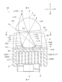
- the lamp unit 1R includes a light source 2, a reflector 3, a lens 4, a heat sink 5, and a fan unit 6.
- the light source 2, reflector 3, lens 4, heat sink 5, and fan unit 6 are attached to a frame member (not shown) and attached to the lamp housing 101 via the frame member and bracket member (not shown). It is
- the front shape of the lens 4 (the front shape of the output surface 41) is a horizontally long shape with a narrow vertical width (vertical width) and a wide horizontal width (horizontal width). Also, the thickness of the lens 4 is thick at the central portion and gradually decreases from the central portion to the peripheral portion. Furthermore, the radius of curvature of the entrance surface 40 is greater than the radius of curvature of the exit surface 41 . That is, the lens 4 of the ADB type lamp units 1L and 1R needs to let the light from the ten light emitting elements LED1 to LED10 enter from the entrance surface 40 and irradiate the vehicle V forward from the exit surface 41. . Therefore, the radius of curvature of the entrance surface 40 is large, and the radius of curvature of the exit surface 41 is small.
- the vehicle outer edge of the first partial light distribution patterns PL1A and PR1A on which the diffuse light distribution patterns PL1C and PR1C are superimposed (hereinafter referred to as "first partial light distribution patterns PL1A and PR1A after superimposition")
- the vehicle-outside vertical cutoff line CL1RC (see FIGS. 5A and 9B) is the first partial light distribution patterns PL1 and PR1 (hereinafter referred to as the first partial light distribution patterns PL1 and PR1 on which the diffuse light distribution patterns PL1C and PR1C are not superimposed).
- first partial light distribution patterns PL1 and PR1 before superimposition in this example, the vehicle outside vertical cutoff line CL1R (see FIGS. 5(B) and 9(B)). Located outside (on the right).
- the vertical cut-off line CL1L (see FIGS. 5A and 9B) of the first partial light distribution patterns PL1A and PR1A after superimposition and the first partial light distribution patterns PL1 and PR1 before superimposition is the same or substantially the same as the vehicle inner longitudinal cut-off line CL1L (see FIGS. 5(B) and 9(B)).
- the extinguished left side The left partial light distribution patterns PL5 to PL8 and the right partial light distribution patterns PR5 to PR8 corresponding to the light emitting elements LED5 to LED8 of the lamp unit 1L and the light emitting elements LED5 to LED8 of the right lamp unit 1R, respectively, As shown by the dashed line in FIG. 12, it disappears or the luminosity decreases. As a result, in the overall high beam light distribution pattern P shown in FIG. 12, the area where the preceding vehicle V2 exists becomes darker than the surrounding areas, and the preceding vehicle V2 is not dazzled.
- the lamp systems 1L, 1R, 100L, and 100R transmit light from the ten light emitting elements LED1 to LED10 through a lens 4 arranged in front of a light source 2 having ten light emitting elements LED1 to LED10.
- 10 partial light distribution patterns PL1 to PL10 and PR1 to PR10 arranged in the horizontal direction in the front direction of the vehicle V.
- the lamp systems 1L, 1R, 100L, and 100R reflect the light L2 from the second light emitting element LED2 located next to the first light emitting element LED1 as the reflected light L21 outside the lens 4 by the inner reflecting surface 30L. is. Therefore, in the lamp systems 1L, 1R, 100L, and 100R, the reflected light L21 from the inner reflecting surface 30L does not pass through the lens 4 to form a light distribution pattern. There is no influence on the 10 partial light distribution patterns PL1 to PL10 and PR1 to PR10.
Landscapes
- Engineering & Computer Science (AREA)
- General Engineering & Computer Science (AREA)
- Physics & Mathematics (AREA)
- Microelectronics & Electronic Packaging (AREA)
- Optics & Photonics (AREA)
- Mechanical Engineering (AREA)
- Geometry (AREA)
- Non-Portable Lighting Devices Or Systems Thereof (AREA)
Abstract
Description
以下、この実施形態にかかる車両用前照灯のランプユニット1L、1R(以下、「ランプユニット1L、1R」と称する)、この実施形態にかかる車両用前照灯100L、100R(以下、「車両用前照灯100L、100R」と称する)の構成について説明する。
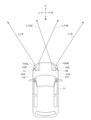
図1に示すように、左側車両用前照灯100Lは、車両Vの前部の左側に装備されていて、右側車両用前照灯100Rは、車両Vの前部の右側に装備されている。
制御装置は、図示されていないが、車両Vに装備されている。制御装置は、検出部と、検出制御部と、点灯消灯制御部と、を有する。
左側車両用前照灯100Lの左側ランプユニット1Lは、図9(A)に示すように、左側ハイビーム配光パターンPLを車両Vの前方に照射する。一方、右側車両用前照灯100Rの右側ランプユニット1Rは、図9(B)に示すように、右側ハイビーム配光パターンPRを車両Vの前方に照射する。
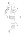
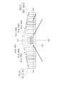
以下、右側ランプユニット1Rについて、図2から図4を参照して説明する。ここで、右側ランプユニット1Rにおいて、車両外側は、車両Vの右側であり、車両内側は、車両Vの左側であり、以下、「車両外側」を「右側」と称し、「車両内側」を「左側」と称する。一方、左側ランプユニット1Lにおいて、車両外側は、車両Vの左側であり、車両内側は、車両Vの右側であり、以下、「車両外側」を「左側」と称し、「車両内側」を「右側」と称する。
光源2は、図2から図4に示すように、複数個、この例では、10個の発光素子LED1、LED2、LED3、LED4、LED5、LED6、LED7、LED8、LED9、LED10(以下、「LED1~LED10」と称する)と、基板20と、を有する。ここで、10個の発光素子LED1~LED10を、左側から第1発光素子LED1~第10発光素子LED10と称する。
リフレクタ3は、光源2とレンズ4との間に配置されている。リフレクタ3は、本体部31と、本体部31の左右両側に一体に設けられている取付部31L、31Rと、を有する。本体部31は、発光素子LED1~LED10よりも下側に配置されている。左側取付部31Lは、発光素子LED1~LED10の左側に配置されている。右側取付部31Rは、発光素子LED1~LED10の右側に配置されている。左右の取付部31L、31Rは、ヒートシンク5の取付部50に取り付けられている。
左側取付部31Lの上端部分には、サイドリフレクタとしての内側反射面30Lが設けられている。内側反射面30Lは、10個の発光素子LED1~LED10よりも左側に設けられている。すなわち、内側反射面30Lは、第1発光素子LED1よりも左側(車両内側)に設けられている。また、内側反射面30Lは、発光素子LED1~LED10よりも前側に設けられている。さらに、内側反射面30Lは、この例では、自由曲面、複数の曲面、一つの曲面、複数の平面や一つの平面など、任意の面から構成されている。
右側取付部31Rの上端部分には、サイドリフレクタとしての外側反射面30Rが設けられている。外側反射面30Rは、10個の発光素子LED1~LED10よりも右側に設けられている。すなわち、外側反射面30Rは、第10発光素子LED10よりも右側(車両外側)に設けられている。また、外側反射面30Rは、発光素子LED1~LED10よりも前側に設けられている。さらに、外側反射面30Rは、この例では、第1焦点F1が第10発光素子LED10に位置し、第2焦点F2がレンズ4の入射面40のうち光軸Zから左側に位置する楕円を上下に延ばした楕円面から構成されている。
レンズ4は、図2および図3に示すように、この例では、投影レンズであって、非球面レンズから構成されている。レンズ4は、入射面40と、出射面41と、光軸Zと、を有する。なお、この例において、光軸Zは、図2に示すように、第6発光素子LED6と第7発光素子LED7との間を通っている。
以下、左右のランプユニット1L、1Rから照射される配光パターンについて、図5~図12を参照して説明する。
10個の部分配光パターンPL1~PL10、PR1~PR10は、前記の通り、10個の発光素子LED1~LED10からの光(10個の発光素子LED1~LED10からの直射光、および、10個の発光素子LED1~LED10からの光)を、レンズ4により制御されて形成されている。
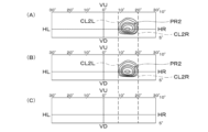
10個の部分配光パターンPL1~PL10、PR1~PR10の左右両端には、それぞれ、左側縦カットオフライン、右側縦カットオフラインが形成されている。たとえば、図5(B)、図9(B)に示すように、右側の第1部分配光パターンPR1の左右両端には、左側縦カットオフラインCL1L、右側縦カットオフラインCL1Rが形成されている。また、図6(A)、(B)、図9(B)に示すように、右側の第2部分配光パターンPR2の左右両端には、左側縦カットオフラインCL2L、右側縦カットオフラインCL2Rが形成されている。さらに、図7(B)、図9(B)に示すように、右側の第10部分配光パターンPR10の左右両端には、左側縦カットオフラインCL10L、右側縦カットオフラインCL10Rが形成されている。さらにまた、図8(A)、(B)、図9(B)に示すように、右側の第9部分配光パターンPR9の左右両端には、左側縦カットオフラインCL9L、右側縦カットオフラインCL9Rが形成されている。
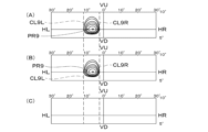
拡散配光パターンPL1C、PR1Cは、図5、図9~図12に示すように、第1発光素子LED1からの光L1であって、内側反射面30Lで反射された反射光L11を、レンズ4により制御されて形成されている。拡散配光パターンPL1C、PR1Cは、10個の部分配光パターンPL1~PL10、PR1~PR10の車両外側の第1部分配光パターンPL1、PR1に重畳されている。
付加配光パターンPL10C、PR10Cは、図7、図9~図12に示すように、第10発光素子LED10からの光L10であって、外側反射面30Rで反射された反射光L101を、レンズ4により制御されて形成されている。
ヒートシンク5は、熱伝導性が高い部材、この例では、アルミダイカスト製の部材から構成されている。ヒートシンク5は、図2から図4に示すように、板形状の取付部50とフィン形状の放熱部51との一体の構造物から構成されている。
ファンユニット6は、図2から図4に示すように、ヒートシンク5の放熱部51の後面に取り付けられている。ファンユニット6は、風をヒートシンク5に強制的にかつ直接当てることにより、ヒートシンク5を、発光素子LED1~LED10において発生した熱から、冷却させる。
この実施形態にかかるランプユニット1L、1R、この実施形態にかかる車両用前照灯100L、100Rは、以上のごとき構成からなり、以下、その作用について説明する。
図10に示すように、対向車V1や先行車V2などの前方車両がいない場合は、制御装置の検出部が、対向車V1や先行車V2などの前方車両を検出していない。このため、左右両側のランプユニット1L、1Rの10個の発光素子LED1~LED10が、全個点灯される。
図11に示すように、対向車V1がいる場合は、制御装置の検出部が、対向車V1を検出する。このため、左右両側のランプユニット1L、1Rの10個の発光素子LED1~LED10のうち、対向車V1がいる領域を照射している発光素子、この例では、左側ランプユニット1Lの発光素子LED8~LED10、および、右側ランプユニット1Rの発光素子LED2~LED5は、制御装置の制御により、消灯もしくは減光される。
図12に示すように、先行車V2がいる場合は、制御装置の検出部が、先行車V2を検出する。このため、左右両側のランプユニット1L、1Rの10個の発光素子LED1~LED10のうち、先行車V2がいる領域を照射している発光素子、この例では、左側ランプユニット1Lの発光素子LED5~LED8および、右側ランプユニット1Rの発光素子LED5~LED8は、制御装置の制御により、消灯もしくは減光される。
発光素子LED1~LED10において発生した熱は、基板20および取付部材であるヒートシンク5を介して、外部に放出される。また、ヒートシンク5は、ファンユニット6による強制空冷により、冷却される。
この実施形態にかかるランプユニット1L、1R、この実施形態にかかる車両用前照灯100L、100R(以下、「ランプシステム1L、1R、100L、100R」と称する)は、以上のごとき構成、作用からなり、以下、その効果について説明する。
なお、前記の実施形態においては、10個の発光素子LED1~LED10により、10個の部分配光パターンが形成されるものである。しかしながら、この発明においては、少なくとも4個の発光素子LED1、LED2、LED9、LED10により、4個の部分配光パターンが形成されるものであっても良い。ちなみに、10個から14個の発光素子により、10個から14個の部分配光パターンが形成されるものが、ハイビーム配光パターンとして、好ましい。
1R 右側ランプユニット(ランプユニット)
2 光源
20 基板
3 リフレクタ
30 反射面
30L 内側反射面
30R 外側反射面
31 本体部
31L 左側取付部
31R 右側取付部
4 レンズ
40 入射面
41 出射面
5 ヒートシンク
50 取付部
51 放熱部
6 ファンユニット
100L 左側車両用前照灯(車両用前照灯)
100R 右側車両用前照灯(車両用前照灯)
101 ランプハウジング
102 ランプレンズ
103 灯室
B 後
CL1L カットオフライン
CL1R カットオフライン
CL1RC カットオフライン
CL2L カットオフライン
CL2R カットオフライン
CL9L カットオフライン
CL9R カットオフライン
CL10L カットオフライン
CL10L カットオフライン
CL10LC カットオフライン
D 下
F 前
F1 第1焦点
F2 第2焦点
HL-HR スクリーンの左右の水平線
L 左
L1 光
L11 反射光
L12 出射光
L2 光
L21 反射光
L9 光
L91 反射光
L10 光
L101 反射光
L102 出射光
LED1、LED2、LED3、LED4、LED5、LED6、LED7、LED8、LED9、LED10(LED1~LED10) 10個の発光素子
P 全体ハイビーム配光パターン
PL 左側ハイビーム配光パターン
PR 右側ハイビーム配光パターン
PL1、PL2、PL3、PL4、PL5、PL6、PL7、PL8、PL9、PL10(PL1~PL10) 左側の10個の部分配光パターン
PL1A 重畳後の左側の第1部分配光パターン
PL1C 左側の拡散配光パターン
PL10A 重畳後の左側の第10部分配光パターン
PL10C 左側の付加配光パターン
PR1、PR2、PR3、PR4、PR5、PR6、PR7、PR8、PR9、PR10(PR1~PR10) 右側の10個の部分配光パターン
PR1A 重畳後の右側の第1部分配光パターン
PR1C 右側の拡散配光パターン
PR10A 重畳後の右側の第10部分配光パターン
PR10C 右側の付加配光パターン
R 右
U 上
V 車両(自車両)
V1 対向車
V2 先行車
VU-VD スクリーンの上下の垂直線
Z 光軸
Claims (9)
- 車両の前部に装備される車両用前照灯のランプユニットであって、
左右に水平方向に配列されている複数個の発光素子を有する光源と、
前記光源の前に配置されているレンズと、
複数個の前記発光素子よりも車両内側に設けられている内側反射面と、
を備え、
前記内側反射面は、前記発光素子のうち最も車両内側に位置する最内側発光素子からの光を反射光として前記レンズに反射させ、
前記レンズは、複数個の前記発光素子からの光を、左右に水平方向に配列されている複数個の部分配光パターンとして、車両の前方に出射させ、前記内側反射面からの前記反射光を、拡散配光パターンとして、前記拡散配光パターンが前記部分配光パターンのうち最も車両外側に位置する最外側部分配光パターンに重畳し、かつ、前記拡散配光パターンの車両外側の縁が前記最外側部分配光パターンの車両外側の縁よりも車両外側に位置するように、車両の前方に出射させる、
ことを特徴とする車両用前照灯のランプユニット。 - 前記拡散配光パターンの領域は、前記最外側部分配光パターンの領域よりも狭い、
ことを特徴とする請求項1に記載の車両用前照灯のランプユニット。 - 前記内側反射面は、前記最内側発光素子の隣に位置する次内側発光素子からの光を前記レンズ以外に反射させる、
ことを特徴とする請求項1に記載の車両用前照灯のランプユニット。 - 前記内側反射面は、
任意の面から構成されていて、
前記最内側発光素子からの光を、前記レンズのうち、前記レンズの光軸よりも車両内側であって、前記レンズの光軸よりも上側の有効部に反射させ、
前記次内側発光素子からの光を、前記レンズの光軸よりも上側であって、前記レンズの有効部以外に反射させる、
ことを特徴とする請求項3に記載の車両用前照灯のランプユニット。 - 複数個の前記発光素子よりも車両外側に設けられている外側反射面を備え、
前記外側反射面は、前記発光素子のうち最も車両外側に位置する最外側発光素子からの光を反射光として前記レンズに反射させ、
前記レンズは、前記外側反射面からの前記反射光を、付加配光パターンとして、前記部分配光パターンのうち最も車両内側に位置する最内側部分配光パターンに付加するように、車両の前方に出射させる、
ことを特徴とする請求項1に記載の車両用前照灯のランプユニット。 - 前記外側反射面は、
第1焦点が前記最外側発光素子に位置し、第2焦点が前記レンズの入射面に位置する楕円面から構成されていて、
前記最外側発光素子からの光を、前記レンズのうち、前記最内側発光素子からの光であって前記内側反射面からの反射光よりも車両外側の有効部に反射させる、
ことを特徴とする請求項5に記載の車両用前照灯のランプユニット。 - 前記光源と前記レンズとの間に配置されているリフレクタを備え、
前記リフレクタは、前記発光素子からの光を前記レンズに反射させる反射面を有し、
前記レンズは、前記発光素子からの光と前記反射面からの光とを重畳させて複数個の前記部分配光パターンとして車両の前方に出射させる、
ことを特徴とする請求項5に記載の車両用前照灯のランプユニット。 - 前記内側反射面および前記外側反射面は、前記リフレクタに設けられている、
ことを特徴とする請求項7に記載の車両用前照灯のランプユニット。 - 車両の前部の左側と右側とにそれぞれ装備される車両用前照灯であって、
灯室を形成するランプハウジングおよびランプレンズと、
前記灯室内に配置されている前記の請求項1に記載の車両用前照灯のランプユニットと、
を備える、
ことを特徴とする車両用前照灯。
Priority Applications (3)
| Application Number | Priority Date | Filing Date | Title |
|---|---|---|---|
| EP22915803.5A EP4459180A4 (en) | 2021-12-28 | 2022-12-19 | LAMP UNIT FOR VEHICLE HEADLIGHT AND VEHICLE HEADLIGHT |
| CN202280086411.XA CN118511031A (zh) | 2021-12-28 | 2022-12-19 | 车辆用前照灯的灯单元、车辆用前照灯 |
| US18/722,282 US12410899B2 (en) | 2021-12-28 | 2022-12-19 | Lamp unit for vehicular headlamp, and vehicular headlamp |
Applications Claiming Priority (2)
| Application Number | Priority Date | Filing Date | Title |
|---|---|---|---|
| JP2021-215032 | 2021-12-28 | ||
| JP2021215032A JP7735860B2 (ja) | 2021-12-28 | 2021-12-28 | 車両用前照灯のランプユニット、車両用前照灯 |
Publications (1)
| Publication Number | Publication Date |
|---|---|
| WO2023127579A1 true WO2023127579A1 (ja) | 2023-07-06 |
Family
ID=86998880
Family Applications (1)
| Application Number | Title | Priority Date | Filing Date |
|---|---|---|---|
| PCT/JP2022/046712 Ceased WO2023127579A1 (ja) | 2021-12-28 | 2022-12-19 | 車両用前照灯のランプユニット、車両用前照灯 |
Country Status (5)
| Country | Link |
|---|---|
| US (1) | US12410899B2 (ja) |
| EP (1) | EP4459180A4 (ja) |
| JP (1) | JP7735860B2 (ja) |
| CN (1) | CN118511031A (ja) |
| WO (1) | WO2023127579A1 (ja) |
Families Citing this family (2)
| Publication number | Priority date | Publication date | Assignee | Title |
|---|---|---|---|---|
| DE102022123124A1 (de) * | 2022-09-12 | 2024-03-14 | HELLA GmbH & Co. KGaA | Beleuchtungsvorrichtung für Fahrzeuge |
| JP2025182912A (ja) * | 2024-06-04 | 2025-12-16 | スタンレー電気株式会社 | 車両用灯具 |
Citations (5)
| Publication number | Priority date | Publication date | Assignee | Title |
|---|---|---|---|---|
| JP2007227228A (ja) * | 2006-02-24 | 2007-09-06 | Koito Mfg Co Ltd | 車両用前照灯の灯具ユニット |
| JP2013110068A (ja) * | 2011-11-24 | 2013-06-06 | Stanley Electric Co Ltd | 車両用灯具ユニット |
| JP2013161577A (ja) * | 2012-02-02 | 2013-08-19 | Koito Mfg Co Ltd | 灯具ユニット |
| JP2014120452A (ja) * | 2012-12-19 | 2014-06-30 | Koito Mfg Co Ltd | 車輌用前照灯 |
| JP2017195116A (ja) | 2016-04-21 | 2017-10-26 | 市光工業株式会社 | 車両用灯具 |
Family Cites Families (7)
| Publication number | Priority date | Publication date | Assignee | Title |
|---|---|---|---|---|
| JP5666882B2 (ja) | 2010-11-18 | 2015-02-12 | 株式会社小糸製作所 | ハイビーム用灯具ユニット |
| JP5666977B2 (ja) * | 2011-04-26 | 2015-02-12 | 株式会社小糸製作所 | 車両用灯具 |
| JP5758724B2 (ja) | 2011-07-07 | 2015-08-05 | 株式会社小糸製作所 | 車輌用前照灯 |
| JP2016115641A (ja) | 2014-12-18 | 2016-06-23 | スタンレー電気株式会社 | 車両用灯具 |
| JP6955418B2 (ja) | 2017-10-13 | 2021-10-27 | 株式会社小糸製作所 | 車両用灯具 |
| JP7269025B2 (ja) | 2019-02-12 | 2023-05-08 | 株式会社小糸製作所 | 車両用灯具 |
| US11674658B2 (en) * | 2019-05-22 | 2023-06-13 | Koito Manufacturing Co., Ltd. | Headlamp for vehicle |
-
2021
- 2021-12-28 JP JP2021215032A patent/JP7735860B2/ja active Active
-
2022
- 2022-12-19 CN CN202280086411.XA patent/CN118511031A/zh active Pending
- 2022-12-19 WO PCT/JP2022/046712 patent/WO2023127579A1/ja not_active Ceased
- 2022-12-19 US US18/722,282 patent/US12410899B2/en active Active
- 2022-12-19 EP EP22915803.5A patent/EP4459180A4/en active Pending
Patent Citations (5)
| Publication number | Priority date | Publication date | Assignee | Title |
|---|---|---|---|---|
| JP2007227228A (ja) * | 2006-02-24 | 2007-09-06 | Koito Mfg Co Ltd | 車両用前照灯の灯具ユニット |
| JP2013110068A (ja) * | 2011-11-24 | 2013-06-06 | Stanley Electric Co Ltd | 車両用灯具ユニット |
| JP2013161577A (ja) * | 2012-02-02 | 2013-08-19 | Koito Mfg Co Ltd | 灯具ユニット |
| JP2014120452A (ja) * | 2012-12-19 | 2014-06-30 | Koito Mfg Co Ltd | 車輌用前照灯 |
| JP2017195116A (ja) | 2016-04-21 | 2017-10-26 | 市光工業株式会社 | 車両用灯具 |
Non-Patent Citations (1)
| Title |
|---|
| See also references of EP4459180A4 |
Also Published As
| Publication number | Publication date |
|---|---|
| EP4459180A4 (en) | 2025-08-27 |
| JP7735860B2 (ja) | 2025-09-09 |
| US12410899B2 (en) | 2025-09-09 |
| CN118511031A (zh) | 2024-08-16 |
| US20250052387A1 (en) | 2025-02-13 |
| EP4459180A1 (en) | 2024-11-06 |
| JP2023098330A (ja) | 2023-07-10 |
Similar Documents
| Publication | Publication Date | Title |
|---|---|---|
| JP7264068B2 (ja) | 車両用灯具 | |
| JP4969958B2 (ja) | 車両用灯具 | |
| JP5592183B2 (ja) | 車両用灯具 | |
| JP5950385B2 (ja) | 車輌用前照灯 | |
| US9243768B2 (en) | Light source for headlight and headlight | |
| WO2017104678A1 (ja) | 車両用灯具及び基板 | |
| US10393337B2 (en) | Vehicular headlamp | |
| JP6651797B2 (ja) | 車両用前照灯 | |
| JP7490514B2 (ja) | 車両用灯具 | |
| JP2018098105A (ja) | 車両用前照灯 | |
| CN108375048A (zh) | 车载灯具 | |
| JP2019204616A (ja) | 車両用灯具 | |
| WO2023127579A1 (ja) | 車両用前照灯のランプユニット、車両用前照灯 | |
| JP4735424B2 (ja) | 車両用灯具 | |
| JP2018116869A (ja) | 灯具 | |
| JP7101547B2 (ja) | 車両用前照灯 | |
| WO2021112063A1 (ja) | 車両用前照灯 | |
| JP7694224B2 (ja) | 車両用ランプユニット装置、車両用ランプ装置、車両用ランプ制御装置 | |
| JP2016115583A (ja) | 車両用灯具 | |
| JP6492675B2 (ja) | 車両用灯具 | |
| JP7285362B2 (ja) | 車両用前照灯 | |
| EP4660523A1 (en) | Vehicle lamp | |
| JP2019117749A (ja) | 車両用灯具 | |
| JP2024075999A (ja) | 車両用灯具 |
Legal Events
| Date | Code | Title | Description |
|---|---|---|---|
| 121 | Ep: the epo has been informed by wipo that ep was designated in this application |
Ref document number: 22915803 Country of ref document: EP Kind code of ref document: A1 |
|
| WWE | Wipo information: entry into national phase |
Ref document number: 18722282 Country of ref document: US |
|
| WWE | Wipo information: entry into national phase |
Ref document number: 202280086411.X Country of ref document: CN |
|
| NENP | Non-entry into the national phase |
Ref country code: DE |
|
| ENP | Entry into the national phase |
Ref document number: 2022915803 Country of ref document: EP Effective date: 20240729 |
|
| WWG | Wipo information: grant in national office |
Ref document number: 18722282 Country of ref document: US |