WO2023127936A1 - アクセスポート部材及びその製造方法 - Google Patents
アクセスポート部材及びその製造方法 Download PDFInfo
- Publication number
- WO2023127936A1 WO2023127936A1 PCT/JP2022/048459 JP2022048459W WO2023127936A1 WO 2023127936 A1 WO2023127936 A1 WO 2023127936A1 JP 2022048459 W JP2022048459 W JP 2022048459W WO 2023127936 A1 WO2023127936 A1 WO 2023127936A1
- Authority
- WO
- WIPO (PCT)
- Prior art keywords
- slit
- access port
- valve
- main body
- valve portion
- Prior art date
- Legal status (The legal status is an assumption and is not a legal conclusion. Google has not performed a legal analysis and makes no representation as to the accuracy of the status listed.)
- Ceased
Links
Images


Classifications
-
- A—HUMAN NECESSITIES
- A61—MEDICAL OR VETERINARY SCIENCE; HYGIENE
- A61M—DEVICES FOR INTRODUCING MEDIA INTO, OR ONTO, THE BODY; DEVICES FOR TRANSDUCING BODY MEDIA OR FOR TAKING MEDIA FROM THE BODY; DEVICES FOR PRODUCING OR ENDING SLEEP OR STUPOR
- A61M39/00—Tubes, tube connectors, tube couplings, valves, access sites or the like, specially adapted for medical use
- A61M39/02—Access sites
- A61M39/0247—Semi-permanent or permanent transcutaneous or percutaneous access sites to the inside of the body
-
- A—HUMAN NECESSITIES
- A61—MEDICAL OR VETERINARY SCIENCE; HYGIENE
- A61M—DEVICES FOR INTRODUCING MEDIA INTO, OR ONTO, THE BODY; DEVICES FOR TRANSDUCING BODY MEDIA OR FOR TAKING MEDIA FROM THE BODY; DEVICES FOR PRODUCING OR ENDING SLEEP OR STUPOR
- A61M39/00—Tubes, tube connectors, tube couplings, valves, access sites or the like, specially adapted for medical use
- A61M39/22—Valves or arrangement of valves
- A61M39/26—Valves closing automatically on disconnecting the line and opening on reconnection thereof
-
- A—HUMAN NECESSITIES
- A61—MEDICAL OR VETERINARY SCIENCE; HYGIENE
- A61M—DEVICES FOR INTRODUCING MEDIA INTO, OR ONTO, THE BODY; DEVICES FOR TRANSDUCING BODY MEDIA OR FOR TAKING MEDIA FROM THE BODY; DEVICES FOR PRODUCING OR ENDING SLEEP OR STUPOR
- A61M39/00—Tubes, tube connectors, tube couplings, valves, access sites or the like, specially adapted for medical use
- A61M39/10—Tube connectors; Tube couplings
-
- A—HUMAN NECESSITIES
- A61—MEDICAL OR VETERINARY SCIENCE; HYGIENE
- A61M—DEVICES FOR INTRODUCING MEDIA INTO, OR ONTO, THE BODY; DEVICES FOR TRANSDUCING BODY MEDIA OR FOR TAKING MEDIA FROM THE BODY; DEVICES FOR PRODUCING OR ENDING SLEEP OR STUPOR
- A61M39/00—Tubes, tube connectors, tube couplings, valves, access sites or the like, specially adapted for medical use
- A61M39/22—Valves or arrangement of valves
- A61M39/24—Check- or non-return valves
-
- F—MECHANICAL ENGINEERING; LIGHTING; HEATING; WEAPONS; BLASTING
- F16—ENGINEERING ELEMENTS AND UNITS; GENERAL MEASURES FOR PRODUCING AND MAINTAINING EFFECTIVE FUNCTIONING OF MACHINES OR INSTALLATIONS; THERMAL INSULATION IN GENERAL
- F16L—PIPES; JOINTS OR FITTINGS FOR PIPES; SUPPORTS FOR PIPES, CABLES OR PROTECTIVE TUBING; MEANS FOR THERMAL INSULATION IN GENERAL
- F16L41/00—Branching pipes; Joining pipes to walls
- F16L41/08—Joining pipes to walls or pipes, the joined pipe axis being perpendicular to the plane of a wall or to the axis of another pipe
- F16L41/16—Joining pipes to walls or pipes, the joined pipe axis being perpendicular to the plane of a wall or to the axis of another pipe the branch pipe comprising fluid cut-off means
-
- A—HUMAN NECESSITIES
- A61—MEDICAL OR VETERINARY SCIENCE; HYGIENE
- A61M—DEVICES FOR INTRODUCING MEDIA INTO, OR ONTO, THE BODY; DEVICES FOR TRANSDUCING BODY MEDIA OR FOR TAKING MEDIA FROM THE BODY; DEVICES FOR PRODUCING OR ENDING SLEEP OR STUPOR
- A61M39/00—Tubes, tube connectors, tube couplings, valves, access sites or the like, specially adapted for medical use
- A61M39/02—Access sites
- A61M2039/0202—Access sites for taking samples
-
- A—HUMAN NECESSITIES
- A61—MEDICAL OR VETERINARY SCIENCE; HYGIENE
- A61M—DEVICES FOR INTRODUCING MEDIA INTO, OR ONTO, THE BODY; DEVICES FOR TRANSDUCING BODY MEDIA OR FOR TAKING MEDIA FROM THE BODY; DEVICES FOR PRODUCING OR ENDING SLEEP OR STUPOR
- A61M39/00—Tubes, tube connectors, tube couplings, valves, access sites or the like, specially adapted for medical use
- A61M39/02—Access sites
- A61M2039/0205—Access sites for injecting media
-
- A—HUMAN NECESSITIES
- A61—MEDICAL OR VETERINARY SCIENCE; HYGIENE
- A61M—DEVICES FOR INTRODUCING MEDIA INTO, OR ONTO, THE BODY; DEVICES FOR TRANSDUCING BODY MEDIA OR FOR TAKING MEDIA FROM THE BODY; DEVICES FOR PRODUCING OR ENDING SLEEP OR STUPOR
- A61M39/00—Tubes, tube connectors, tube couplings, valves, access sites or the like, specially adapted for medical use
- A61M39/02—Access sites
- A61M39/0247—Semi-permanent or permanent transcutaneous or percutaneous access sites to the inside of the body
- A61M2039/0258—Semi-permanent or permanent transcutaneous or percutaneous access sites to the inside of the body for vascular access, e.g. blood stream access
-
- A—HUMAN NECESSITIES
- A61—MEDICAL OR VETERINARY SCIENCE; HYGIENE
- A61M—DEVICES FOR INTRODUCING MEDIA INTO, OR ONTO, THE BODY; DEVICES FOR TRANSDUCING BODY MEDIA OR FOR TAKING MEDIA FROM THE BODY; DEVICES FOR PRODUCING OR ENDING SLEEP OR STUPOR
- A61M39/00—Tubes, tube connectors, tube couplings, valves, access sites or the like, specially adapted for medical use
- A61M39/02—Access sites
- A61M39/0247—Semi-permanent or permanent transcutaneous or percutaneous access sites to the inside of the body
- A61M2039/027—Semi-permanent or permanent transcutaneous or percutaneous access sites to the inside of the body having a particular valve, seal or septum
-
- A—HUMAN NECESSITIES
- A61—MEDICAL OR VETERINARY SCIENCE; HYGIENE
- A61M—DEVICES FOR INTRODUCING MEDIA INTO, OR ONTO, THE BODY; DEVICES FOR TRANSDUCING BODY MEDIA OR FOR TAKING MEDIA FROM THE BODY; DEVICES FOR PRODUCING OR ENDING SLEEP OR STUPOR
- A61M39/00—Tubes, tube connectors, tube couplings, valves, access sites or the like, specially adapted for medical use
- A61M39/02—Access sites
- A61M39/0247—Semi-permanent or permanent transcutaneous or percutaneous access sites to the inside of the body
- A61M2039/0276—Semi-permanent or permanent transcutaneous or percutaneous access sites to the inside of the body for introducing or removing fluids into or out of the body
-
- A—HUMAN NECESSITIES
- A61—MEDICAL OR VETERINARY SCIENCE; HYGIENE
- A61M—DEVICES FOR INTRODUCING MEDIA INTO, OR ONTO, THE BODY; DEVICES FOR TRANSDUCING BODY MEDIA OR FOR TAKING MEDIA FROM THE BODY; DEVICES FOR PRODUCING OR ENDING SLEEP OR STUPOR
- A61M39/00—Tubes, tube connectors, tube couplings, valves, access sites or the like, specially adapted for medical use
- A61M39/02—Access sites
- A61M39/0247—Semi-permanent or permanent transcutaneous or percutaneous access sites to the inside of the body
- A61M2039/0288—Semi-permanent or permanent transcutaneous or percutaneous access sites to the inside of the body protectors, caps or covers therefor
-
- A—HUMAN NECESSITIES
- A61—MEDICAL OR VETERINARY SCIENCE; HYGIENE
- A61M—DEVICES FOR INTRODUCING MEDIA INTO, OR ONTO, THE BODY; DEVICES FOR TRANSDUCING BODY MEDIA OR FOR TAKING MEDIA FROM THE BODY; DEVICES FOR PRODUCING OR ENDING SLEEP OR STUPOR
- A61M39/00—Tubes, tube connectors, tube couplings, valves, access sites or the like, specially adapted for medical use
- A61M39/10—Tube connectors; Tube couplings
- A61M2039/1072—Tube connectors; Tube couplings with a septum present in the connector
-
- A—HUMAN NECESSITIES
- A61—MEDICAL OR VETERINARY SCIENCE; HYGIENE
- A61M—DEVICES FOR INTRODUCING MEDIA INTO, OR ONTO, THE BODY; DEVICES FOR TRANSDUCING BODY MEDIA OR FOR TAKING MEDIA FROM THE BODY; DEVICES FOR PRODUCING OR ENDING SLEEP OR STUPOR
- A61M39/00—Tubes, tube connectors, tube couplings, valves, access sites or the like, specially adapted for medical use
- A61M39/22—Valves or arrangement of valves
- A61M39/24—Check- or non-return valves
- A61M2039/2426—Slit valve
-
- A—HUMAN NECESSITIES
- A61—MEDICAL OR VETERINARY SCIENCE; HYGIENE
- A61M—DEVICES FOR INTRODUCING MEDIA INTO, OR ONTO, THE BODY; DEVICES FOR TRANSDUCING BODY MEDIA OR FOR TAKING MEDIA FROM THE BODY; DEVICES FOR PRODUCING OR ENDING SLEEP OR STUPOR
- A61M2205/00—General characteristics of the apparatus
- A61M2205/02—General characteristics of the apparatus characterised by a particular materials
- A61M2205/0216—Materials providing elastic properties, e.g. for facilitating deformation and avoid breaking
-
- A—HUMAN NECESSITIES
- A61—MEDICAL OR VETERINARY SCIENCE; HYGIENE
- A61M—DEVICES FOR INTRODUCING MEDIA INTO, OR ONTO, THE BODY; DEVICES FOR TRANSDUCING BODY MEDIA OR FOR TAKING MEDIA FROM THE BODY; DEVICES FOR PRODUCING OR ENDING SLEEP OR STUPOR
- A61M2207/00—Methods of manufacture, assembly or production
Definitions
- the present invention relates to an access port member that is connected to a blood circuit for extracorporeal circulation of a patient's blood and that allows blood collection or administration by a connection member such as a syringe, and a manufacturing method thereof.
- a blood circuit that is used during blood purification treatment such as dialysis treatment and that circulates the patient's blood extracorporeally is generally mainly composed of a flexible tube, and an access port member ("rubber (also called a "button” or “co-injection member”) is connected.
- an access port member also called a "button” or "co-injection member”
- a conventional access port member as disclosed in Patent Document 1, there is provided a main body connected to a blood circuit, a valve section having a slit, and fixing to the main body while holding the valve section. and a cap portion.
- the tip of the connecting member such as a syringe presses the peripheral portion of the slit in the valve portion, and the pressing force changes the slit from the closed state to the open state.
- the valve portion is made of an elastic member such as a rubber material, the closed state of the slit can be maintained by its elastic force.
- the cap portion is welded and fixed to the main body portion by ultrasonic welding or the like. There is a risk that excessive stress will be applied to the valve portion, resulting in reduced durability. In addition, since the air in the space surrounded by the welded portion between the body portion and the cap portion is compressed during welding, excessive compressive force may be generated and the durability of the valve portion may be reduced.
- the valve portion is made of an elastic member that is circular in plan view. It has become difficult to In particular, when a linear slit is formed in the valve portion and it is desired to extend the linear slit parallel to the direction in which blood flows (that is, the extending direction of the flow path), the direction of the slit is visually observed. It is necessary to carefully attach the valve portion to the main body, and there is a problem that the attachment work takes time.
- the present invention has been made in view of such circumstances, and an object of the present invention is to provide an access port member capable of suppressing deterioration in the durability of the valve portion caused by welding and fixing the cap portion to the main body portion, and a manufacturing method thereof. It is an object of the present invention to provide a method and an access port member in which a valve portion can be easily attached to an attachment portion of a body portion while extending a slit in a desired direction.
- An access port member comprises a body portion having an opening, an elastic member attached to a mounting portion of the body portion covering the opening, and a connecting member capable of collecting blood or administering medication.
- a valve portion formed with a slit that is pressed by a tip end of the valve portion to open from a closed state;
- An access port member comprises a main body portion having an opening, and an elastic member attached to a mounting portion of the main body portion in a press-fitted state so as to cover the opening.
- a valve portion formed with a linear slit that is pressed by the tip of a connecting member that allows administration of medication to be opened from a closed state; and the body portion sandwiching the valve portion with the slit facing the outside and a cap portion having a lock portion formed with a thread shape that is screwed and locked with the thread shape formed on the connection member, and the valve portion is attached to the main body portion It is attached so as to conform to the shape of the part and has an asymmetrical shape between the extension direction of the flow passage and the orthogonal direction.
- the present invention is composed of a main body having an opening, and an elastic member attached to the attachment of the main body so as to cover the opening.
- a valve portion formed with a slit that is open; and a thread shape and thread formed on the connecting member, which are welded and fixed to the main body portion while sandwiching the valve portion while exposing the slit to the outside.
- a cap portion having a locking portion formed with a threaded shape for locking together, and a position between the welding portion and the mounting portion of the main body portion, or formed between the welding portion of the cap portion and the clamping portion of the valve portion. Since the cap portion is welded and fixed to the main body portion, deterioration in durability of the valve portion can be suppressed.
- the elastic member includes a main body having an opening and an elastic member that is press-fitted to the mounting portion of the main body so as to cover the opening, and is pressed against the protruding end of the connection member capable of collecting blood or administering medication.
- a valve portion formed with a linear slit that is opened from a closed state by being opened, and a connecting member that is fixed to the main body portion in a state in which the valve portion is sandwiched while exposing the slit to the outside, and is formed in the connection member.
- valve portion is attached so as to match the shape of the attachment portion in the main body portion, and the flow path is extended. Since the shape is asymmetric with respect to the direction and the orthogonal direction, the valve portion can be easily attached to the attachment portion of the main body portion while extending the slit in a desired direction.
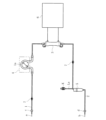
- FIG. 1 Schematic diagram showing a blood circuit to which an access port member according to an embodiment of the present invention is applied
- the perspective view which shows the same access port member.
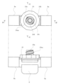
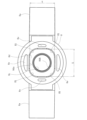
- the top view and side view which show the same access port member.
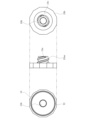
- An exploded perspective view showing the same access port member The top view which shows the main-body part of the same access port member.
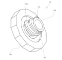
- Three views showing the valve portion of the same access port member Three views showing the cap portion of the access port member Perspective view of the same cap as seen from above Perspective view of the same cap as seen from below
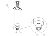
- the perspective view which shows the syringe (connection member) applied to the same access port member.
- FIG. 11 is a vertical cross-sectional view showing an access port member according to another embodiment;
- FIG. 11 is a perspective view showing an access port member according to still another embodiment of the present invention;
- FIG. 1 A three-sided view showing the cap portion of the same access port member.
- XXVI-XXVI line sectional view in FIG. A plan view showing the valve portion of the access port member according to the second embodiment.
- a plan view showing a valve portion of an access port member according to another embodiment Sectional view showing an access port member according to another embodiment
- the access port member according to the first embodiment is connected to a blood circuit for extracorporeal circulation of a patient's blood, and is capable of collecting or administering blood by means of a connecting member such as a syringe.
- a connecting member such as a syringe.
- the arterial blood circuit 1 consists of a flexible tube through which a predetermined liquid can flow, and an arterial puncture needle a can be attached to the distal end thereof via a connector c.
- a tube to be ironed 1 a is connected in the middle of the arterial blood circuit 1 , and the tube to be ironed 1 a can be attached to the blood pump 4 .
- the blood pump 4 is composed of a squeezing-type pump capable of feeding the priming liquid and the patient's blood (liquid) within the blood circuit, and can circulate the patient's blood extracorporeally by being driven.
- the venous blood circuit 2 is made of a flexible tube that allows a predetermined liquid to flow, and a venous puncture needle b can be attached to the tip of the flexible tube through a connector d.
- An air trap chamber 5 is connected in the middle of the venous blood circuit 2 so as to remove air contained in extracorporeally circulating blood in the blood circuit. Further, from the upper part of the air trap chamber 5, a liquid medicine injection line La having a connecting part K attached to the tip thereof and capable of injecting a liquid medicine into the blood circuit extends. It should be noted that a blood circuit that does not include the liquid injection line La in the upper portion of the air trap chamber 5 may be used.
- the dialyzer 3 is configured by housing a plurality of hollow fiber membranes with micropores formed therein in a housing portion, and can introduce the dialysate from the dialyzer main body 6 and dialyze the waste liquid. By discharging to the device main body 6, the extracorporeally circulating blood in the blood circuit can be purified. That is, the dialyzer 3 is connected between the arterial blood circuit 1 and the venous blood circuit 2, and the blood pump 4 is driven while the patient is punctured by the arterial puncture needle a and the venous puncture needle b. Thus, the patient's blood can be extracorporeally circulated through the blood circuit (arterial blood circuit 1 and venous blood circuit 2) and the dialyzer 3, and the blood can be purified and returned to the patient.
- a predetermined portion of the arterial blood circuit 1 for example, a portion between the connector c and the blood pump 4 as illustrated
- a predetermined portion of the venous blood circuit 2 for example, As shown, an access port member 7 is connected to the portion between the dialyzer 3 and the air trap chamber 5).
- the access port member 7 enables blood collection or administration of extracorporeal blood circulating in the blood circuit, and as shown in FIGS. and
- the access port member 7 is not limited to the blood circuit, and may be connected to, for example, the liquid injection line La.
- the body portion 8 is made of resin molded parts and is connected to a predetermined portion of a blood circuit (arterial blood circuit 1 or venous blood circuit 2) for extracorporeally circulating a patient's blood, as shown in FIGS.
- a flow passage 8b for circulating blood is formed inside, and an opening 8c communicating with the flow passage 8b is provided.
- the main body portion 8 has connection portions 8a formed at both ends thereof, which are connectable to the flexible tubes constituting the blood circuit, and valve portions formed at the opening edges of the opening portion 8c. 9 and a concave portion 8e formed around the mounting portion 8d.
- the mounting portion 8d has a concave shape formed in the opening peripheral portion of the opening portion 8c, and has a shape following the contour shape of the valve portion 9 (a shape following a rectangle in this embodiment).
- the dimensions of this mounting portion 8d are set to be slightly smaller than the external dimensions of the valve portion 9, so that the valve portion 9 can be mounted in a press-fitted state. As a result, the valve portion 9 is fixed in a state in which a compressive force is applied from the outer peripheral portion toward the inside, thereby firmly closing the slit 9a.
- the valve portion 9 is made of an elastic member (rubber material) attached to the attachment portion 8d of the main body portion 8 so as to cover the opening portion 8c, and has a straight slit 9a formed in the central portion.
- the valve portion 9 according to the present embodiment has a rectangular contour shape having a long side A and a short side B in a plan view, and a slit 9a extends in a direction parallel to the long side A of the rectangle. is set.
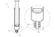
- the slit 9a is changed from the closed state (see FIG. 15) to the open state (see FIG. 15) by pressing the surface of the valve portion 9 with the tip 11a (see FIG. 13) of the syringe 11 (connecting member) capable of collecting or administering blood. 16 and 17).
- the syringe 11 applied to this embodiment is capable of sucking or ejecting liquid, and is capable of collecting blood (collecting blood) from the tip 11a by a suction action, or Medicine can be administered (medicated) from the tip 11a by the ejection action.
- a threaded shape 11b that can be screwed together with a threaded shape 10aa formed on the lock portion 10a of the cap portion 10 is integrally formed on the outer peripheral portion of the tip 11a of the syringe 11 .
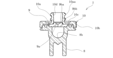
- an annular rib 9b is formed so as to protrude around the slit 9a.
- the rib 9b consists of a convex portion (thick-walled portion) that continuously protrudes around the periphery of the slit 9a on the surface of the valve portion 9, and is formed following the shape of the tip 11a of the syringe 11, It has a tip surface 9ba and side surfaces 9bb.
- the rib 9b according to the present embodiment has a circular shape in plan view, and a linear slit 9a is formed in the internal region 9bc.
- the internal region 9bc of the rib 9b is a thin portion
- the slit 9a is formed in the thin portion
- the rib 9b is formed around the thin portion to increase the strength of the valve portion 9. is being improved.
- the slit 9a is formed in the thin portion of the inner region 9bc of the rib 9b, so that the slit 9a can be opened from the closed state without applying a very large pressing force to the rib 9b.
- Sufficient strength can be obtained by the ribs 9b, and it is possible to suppress the formation of steps in the slits 9a even when the ribs 9b are repeatedly pressed.
- the rib 9b matches and seals the tip 11a of the syringe 11 (connection member) when the slit 9a is in the open state, and also seals the tip 11a of the syringe 11.
- the slit 9a changes from the closed state (see FIG. 15) to the open state (see FIGS. 16 and 17) in the process of inserting the syringe 11a, and the slit 9a changes from the open state to the closed state in the process of extracting the tip 11a of the syringe 11.
- the state of contact with the tip 11a of the syringe 11 is maintained up to the point of contact.
- the tip 11a of the syringe 11 is brought into contact with the tip surface 9ba of the rib 9b (FIG. 15), and the syringe 11 is pushed in so that the tip 11a of the syringe 11 and the rib 9b are in contact with each other.
- the slit 9a is opened while maintaining contact with the tip surface 9ba (FIG. 16).
- the tip 11a of the syringe 11 contacts the tip surface 9ba of the rib 9b and then the side surface 9bb (FIG. 17). A seal is maintained between the tip 11a and the rib 9b.
- the slit 9a can be opened while maintaining contact between the tip 11a of the syringe 11 and the tip surface 9ba of the rib 9b.
- the tip 11a of the syringe 11 may be brought into contact with the side surface of the rib 9b to maintain the seal. good.
- the rib 9b according to the present embodiment is made of a convex portion formed on the front surface of the valve portion 9, it may be made of a convex portion formed on the back surface of the valve portion 9, or the valve portion 9 It may consist of projections formed on both the front and back surfaces of the .
- the rib 9b according to the present embodiment is circular in plan view, it may be elliptical or rectangular in plan view and the slit 9a is formed in the inner region 9bc.
- the slit 9a may be formed in a cross shape instead of a straight line shape.
- the cap portion 10 is made of a part obtained by resin molding, and as shown in FIGS. As shown in FIGS. 9 to 11, it has a lock portion 10a, an outer peripheral edge portion 10b, an inner peripheral concave portion 10c, and a communicating hole 10d. Specifically, a lock portion 10a is formed to protrude along the central axis of the cap portion 10, and an inner peripheral recess 10c is formed around the lock portion 10a. is located at the outer peripheral edge 10b.
- the lock portion 10a has a communication hole 10d into which the tip 11a of the syringe 11 can be inserted and removed, and has a helical screw shape 10aa on the outer peripheral surface that matches the screw shape 11b of the syringe 11 and can be screwed together. are integrally formed.
- FIG. 14 by inserting the tip 11a of the syringe 11 into the communication hole 10d and rotating the syringe 11, the threaded shape 11b of the syringe 11 and the threaded shape 10aa of the lock portion 10a are screwed together.
- the syringe 11 can be connected to the access port member 7 while being locked (fixed).
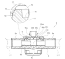
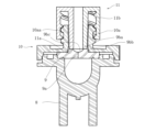
- the access port member in the access port member according to the present embodiment, as shown in FIG. 4, after the welded portion Y1 of the main body portion 8 and the welded portion Y2 of the cap portion 10 are aligned (see FIG. 18), ultrasonic waves are applied. Then, the body portion 8 and the cap portion 10 are welded and fixed (ultrasonic welding) by melting the welded portion Y1 and the welded portion Y2. That is, as shown in FIGS. 9 and 11, the welded portion Y2 of the cap portion 10 is formed along the inner periphery of the outer peripheral edge portion 10b, and the welded portion Y1 of the main body portion 8 coincides with the welded portion Y2. It is formed in a circular shape, and as shown in FIG. 18, by ultrasonically welding the welded portions Y1 and Y2 in a state in which they are aligned, the welded portions Y1 and Y2 are melted to melt the main body. Part 8 and cap part 10 are fixed.
- the main body portion 8 is a flat surface positioned around the mounting portion 8d and has a concave portion between the welding portion Y1 and the mounting portion 8d. 8e are formed.
- the recessed portion 8e is formed in the main body portion 8 as described above, and corresponds to each side (long side A and short side B) of the valve portion 9 attached to the mounting portion 8d of the main body portion 8. are formed in multiple ways.
- the recess 8e according to the present embodiment is formed in the body portion 8, it is formed between the welded portion Y2 of the cap portion 10 and the holding portion of the valve portion 9, or the body portion 8 and the cap. It may be formed on both parts 10 .
- the valve portion 9 is made of an elastic member formed in a rectangular shape (rectangular shape) in a plan view having a long side A and a short side B.
- the portion 8d is formed in a rectangle (rectangular shape) following the shape of the valve portion 9, and the recessed portion 8e is formed outside each side (long side A and short side B) of the valve portion 9 attached to the mounting portion 8d. are formed corresponding to the positions of .
- the access port member 7 includes the main body 8 having the opening 8c, and the elastic member attached to the mounting portion 8d of the main body 8 so as to cover the opening 8c.
- a valve portion 9 formed with a slit 9a that is pressed by a tip 11a of a connection member such as a syringe 11 to open from a closed state, and a main body in which the valve portion 9 is sandwiched while the slit 9a faces the outside.
- the position between the cap portion 10 welded and fixed to the portion 8 and the welded portion Y1 of the main body portion 8 and the mounting portion 8d, or between the welded portion Y2 of the cap portion 10 and the pinching portion of the valve portion 9. Since the recessed portion 8 e is provided, it is possible to suppress deterioration in the durability of the valve portion 9 due to welding and fixing the cap portion 10 to the main body portion 8 .
- the main body 8 since the main body 8 is connected to a predetermined portion of a blood circuit for extracorporeal circulation of the patient's blood, the following effects can be achieved. That is, if a stagnant portion is generated on the back surface of the valve portion 9, it may cause blood coagulation, so it is necessary to reduce the stagnant portion as much as possible. On the other hand, if the valve portion 9 is brought closer to the channel side in order to suppress retention, the tip 11a of the syringe 11 cannot sufficiently push the valve portion 9, and the slit 9a becomes difficult to open.
- the tip 11a of the syringe 11 can sufficiently push the valve portion 9, thereby facilitating the opening of the slit 9a and reducing the retention portion. You can do both.
- valve portion 9 is made of an elastic member formed in a rectangular shape (rectangular shape) in a plan view. , and a plurality of recesses 8e are formed corresponding to each side (long side A and short side B) of the valve portion 9 attached to the attachment portion 8d. It is possible to reliably flow the resin. It should be noted that the valve portion 9 may have other shapes, and in particular, when the valve portion 9 is circular in plan view, the concave portion 8e may be a circular groove surrounding the outer periphery of the valve portion 9 .
- the recessed portion 8e is formed by thinning the main body portion 8 or the cap portion 10, the effect of thinning (prevention of sink marks, etc.) and the effect of allowing the molten resin flowing from the welding portions Y1 and Y2 to flow in (the effect of the valve portion 9 is reduced). maintenance of durability). Specifically, if a sink occurs in part of the side surface or bottom surface (see FIGS. 6 and 7) of the attachment portion 8d of the valve portion 9, the compressive force between the valve portion 9 and the attachment portion 8d is reduced. Since there is a risk that the closing force of the slit 9a will be reduced, such a problem can be prevented by forming the recessed portion 8e from the main body portion 8 or the cap portion 10. As shown in FIG. Furthermore, since the welded portion Y1 of the body portion 8 and the welded portion Y2 of the cap portion 10 are aligned and melted, the cap portion 10 can be fixed to the body portion 8 with high accuracy.
- the body part 8 and the cap part 10 are welded by ultrasonic welding in which ultrasonic waves are applied to the welded parts (Y1, Y2), the body part 8 and the cap part 10 are easily and accurately fixed.
- the cap portion 10 is fixed to the main body portion 8 by ultrasonic welding, but the cap portion 10 is fixed to the main body portion 8 by another welding method such as laser welding or heat welding. You may make it
- the flow path 8b is formed inside to be connected to a predetermined portion of the blood circuit for extracorporeal circulation of the patient's blood, and the flow path 8b allows the blood to circulate. and an elastic member attached to the attachment portion 8d of the body portion 8 covering the opening portion 8c.
- a valve portion 9 formed with a slit 9a that is pressed from a closed state to an open state by being pressed against the cap portion 9; , and the rib 9b integrally formed around the slit 9a in the valve portion 9, it is possible to easily perform the connection work of the syringe 11 (connecting member) while suppressing the closing failure of the slit 9a.
- the cap portion 10 has the locking portion 10a formed with the thread shape 10aa that is screwed and locked with the thread shape 11b of the syringe 11 (connecting member), so that the following effects can be obtained. can. That is, since the size of the locking portion 10a is strictly defined by the standard, the slit 9a of the valve portion 9 cannot be sufficiently pushed by the tip 11a of the syringe 11 (connecting member), and the slit 9a is sufficiently opened. may not.
- the valve portion 9 can be sufficiently pushed by the tip 11a of the syringe 11, thereby facilitating the opening of the slit 9a and suppressing the stagnant portion. You can do both.
- the connecting member to be applied is not limited to the syringe 11, but has a tip that can press the rib 9b, and by pressing the slit 9a from the closed state to the open state, other connecting members that can collect blood or administer medicine (for example, the tip of an infusion tube) a connecting member attached to the device).
- the valve portion 9 is not limited to having a rectangular contour shape in plan view, and may be square, circular, elliptical or rectangular in plan view.
- the present invention is not limited to the one connected to the blood flow path in the blood circuit, and various flow paths extending from the blood circuit (medical fluid flow path such as a chemical injection line, a chemical fluid delivery line, etc.) ). More specifically, in addition to the blood circuit for extracorporeal circulation of the patient's blood, it is connected to a liquid feed circuit for transfusion of drug solutions and blood transfusion, and sampling of blood flowing through the liquid feed circuit, sampling of drug solutions, and injection of drug solutions. It can be applied to things used for such as.
- one end is connected to an infusion bag, and the other end is connected to a connector that is connected to an infusion line such as an indwelling needle or a blood circuit, enabling administration and sampling.
- a connector that is connected to an infusion line such as an indwelling needle or a blood circuit, enabling administration and sampling.
- It may be an access port member that is connected to a drug solution delivery circuit that extends from various filters such as a blood purifier such as the dialyzer 3, a blood adsorber, and a plasma separator, and that allows administration and sampling. good.
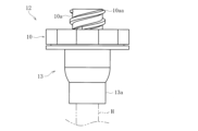
- the access port member 12 when applied to a liquid feeding circuit, the access port member 12 having the configuration shown in FIGS. 19 and 20 can be used.
- the access port member 12 comprises a main body 13 having an opening 13b and an elastic member attached to a mounting portion of the main body 13 so as to cover the opening 13b.
- the valve portion 9 is formed with a slit 9a which is pressed by the tip 11a of the valve portion 9 to open from the closed state, and the valve portion 9 is fixed to the main body portion 13 while the slit 9a is exposed to the outside and the valve portion 9 is sandwiched.
- a cap portion 10 having a lock portion 10a formed with a screw shape 10aa that is screwed and locked with a screw shape 11b formed on the syringe 11, and a rib integrally formed around the slit 9a in the valve portion 9. 9b.
- the tip of the liquid feeding circuit H is connected to a connecting portion 13a formed in the main body portion 13.
- An access port member 12 may be used instead of the connecting portion K shown in FIG.
- the access port member 7 may be provided with a cap portion G.
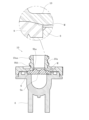
- the access port member 7 includes a body portion 8 similar to those shown in FIGS. 6 to 8, and a valve portion 9 having a slit 9a. It is designed to be In this case, the cap portion G is fixed to the main body portion 8 in a state in which the valve portion 9 is sandwiched while exposing the slit 9a to the outside through the insertion hole Gb. It is configured to have a lock portion Ga formed with a threaded shape Gaa that is screwed and locked. Also, on the rear surface of the cap portion G, an inclined surface M similar to that described above is formed. , the inclined surface M presses the valve portion 9 to compress it in the direction of closing the slit 9a.
- the cap portion G is provided with projections Gca and Gcb formed at positions corresponding to the recessed portions 8e of the body portion 8 and notches N (see FIG. 21) of the body portion 8.
- a projecting portion Gd formed at a corresponding position is integrally formed.
- the protrusions Gca and Gcb have a protruding shape that is fitted into the recess 8e as shown in FIGS.
- the adjacent convex portion Gca and the convex portion Gcb adjacent to the short side B of the valve portion 9 are set to have different dimensions.
- the recessed portion 8e is formed by thinning, and has a recessed portion 8e corresponding to the projecting portion Gca adjacent to the long side A and a recessed portion 8e corresponding to the projecting portion Gcb adjacent to the short side B.
- the cap portion G when the cap portion G is attached to the attachment portion 8d of the main body portion 8, positioning in the rotational direction is possible by fitting the protrusions Gca and Gcb into the recesses 8e.
- the large-sized convex portion Gca cannot fit into the small-sized concave portion 8e and comes into contact with the peripheral surface thereof. More energy than necessary can be applied to signal an error.
- the cap portion G since the cap portion G is formed with an inclined surface M for compressing the slit 9a in the closing direction with respect to the valve portion 9, the inclined surface M can be accurately positioned so as to be parallel to the slit 9a. .
- the convex portions Gca and Gcb of the cap portion G can be fitted, and the inclined surface M can be accurately positioned so as to be parallel to the slit 9a.
- the protruding portion Gd faces the wall surface of the notch N as shown in FIGS. It's becoming As a result, when attaching the cap portion G, it is possible to visually confirm whether or not the positioning in the rotational direction is correct.
- a pair of left and right projecting portions Gd are formed as shown in the figure, either one of them may be formed, or the projecting portion Gd may not be formed.
- the access port member according to the second embodiment is connected to a blood circuit for extracorporeal circulation of a patient's blood, and is capable of collecting or administering blood by means of a connecting member such as a syringe.
- a connecting member such as a syringe.
- a predetermined portion of the arterial blood circuit 1 for example, a portion between the connector c and the blood pump 4 as illustrated
- a predetermined portion of the venous blood circuit 2 for example, As shown, an access port member 7 is connected to the portion between the dialyzer 3 and the air trap chamber 5).
- the access port member 7 enables blood collection or administration of extracorporeal blood circulating in the blood circuit, and as shown in FIGS. and
- the access port member 7 is not limited to the blood circuit, and may be connected to, for example, the liquid injection line La.
- the body portion 8 is made of resin molded parts and is connected to a predetermined portion of a blood circuit (arterial blood circuit 1 or venous blood circuit 2) for extracorporeally circulating a patient's blood, as shown in FIGS.
- a flow passage 8b for circulating blood is formed inside, and an opening 8c communicating with the flow passage 8b is provided.
- the main body portion 8 has connection portions 8a formed at both ends thereof, which are connectable to the flexible tubes constituting the blood circuit, and valve portions formed at the opening edges of the opening portion 8c. 9 and a concave portion 8e formed around the mounting portion 8d.
- the mounting portion 8d has a concave shape formed in the opening peripheral portion of the opening portion 8c, and has a shape following the contour shape of the valve portion 9 (a shape following a rectangle in this embodiment).
- the dimensions of this mounting portion 8d are set to be slightly smaller than the external dimensions of the valve portion 9, so that the valve portion 9 can be mounted in a press-fitted state. Accordingly, when the valve portion 9 is attached so as to conform to the shape of the attachment portion 8d of the main body portion 8, the valve portion 9 is fixed in a state in which a compressive force is applied from the outer peripheral portion toward the inside, and the slit 9a is firmly closed. It is designed to
- the valve portion 9 is made of an elastic member (rubber material) press-fitted to the mounting portion 8d of the main body portion 8 while covering the opening portion 8c, and has a straight slit 9a formed in the center portion.
- the valve portion 9 according to the present embodiment has a rectangular contour shape having a long side A and a short side B in a plan view, and a slit 9a extends in a direction parallel to the long side A of the rectangle. is set.
- the slit 9a is changed from the closed state (see FIG. 15) to the open state (see FIG. 15) by pressing the surface of the valve portion 9 with the tip 11a (see FIG. 13) of the syringe 11 (connecting member) capable of collecting or administering blood. 16 and 17).
- the valve portion 9 has a rectangular shape having a long side A and a short side B in a plan view. Since the shape is asymmetric with respect to the orthogonal direction v (the shape does not match when rotated by 90° between the extending direction u and the orthogonal direction v), by fitting the valve portion 9 to the mounting portion 8d, , the slit 9a always extends in a predetermined direction. In particular, in this embodiment, since the slit 9a extends in a direction parallel to the long side A of the rectangle that is the shape of the valve portion 9, by fitting the valve portion 9 to the mounting portion 8d, The slit 9a extends in the extending direction of the flow path 8b.
- valve portion 9 according to the present embodiment when the valve portion 9 according to the present embodiment is fitted to the mounting portion 8d and is press-fitted, a compressive force is applied from the outer peripheral edge toward the inside, and the long side A is compressed from the short side B. Since the pressure receiving area is larger in , the compressive force in the direction to close the slit 9a can be made larger than the compressive force in the direction to open it. That is, according to the valve portion 9 according to the present embodiment, the slit 9a is naturally extended in the extending direction of the flow passage 8b by being press-fitted so as to match the mounting portion 8d. The slit 9a can be closed by the compressive force.
- the syringe 11 applied to this embodiment is capable of sucking or ejecting liquid, and is capable of collecting blood (collecting blood) from the tip 11a by a suction action, or Medicine can be administered (medicated) from the tip 11a by the ejection action.
- a threaded shape 11b that can be screwed together with a threaded shape 10aa formed on the lock portion 10a of the cap portion 10 is integrally formed on the outer peripheral portion of the tip 11a of the syringe 11 .
- an annular rib 9b is formed so as to protrude around the slit 9a.
- the rib 9b consists of a convex portion (thick-walled portion) that continuously protrudes around the periphery of the slit 9a on the surface of the valve portion 9, and is formed following the shape of the tip 11a of the syringe 11, It has a tip surface 9ba and side surfaces 9bb.
- the rib 9b according to the present embodiment has a circular shape in plan view, and a linear slit 9a is formed in the internal region 9bc.
- the internal region 9bc of the rib 9b is a thin portion
- the slit 9a is formed in the thin portion
- the rib 9b is formed around the thin portion to increase the strength of the valve portion 9. is being improved.
- the slit 9a is formed in the thin portion of the inner region 9bc of the rib 9b, so that the slit 9a can be opened from the closed state without applying a very large pressing force to the rib 9b.
- Sufficient strength can be obtained by the ribs 9b, and it is possible to suppress the formation of steps in the slits 9a even when the ribs 9b are repeatedly pressed.
- the rib 9b matches and seals the tip 11a of the syringe 11 (connection member) when the slit 9a is in the open state, and also seals the tip 11a of the syringe 11.
- the slit 9a changes from the closed state (see FIG. 15) to the open state (see FIGS. 16 and 17) in the process of inserting the syringe 11a, and the slit 9a changes from the open state to the closed state in the process of extracting the tip 11a of the syringe 11.
- the state of contact with the tip 11a of the syringe 11 is maintained up to the point of contact.
- the tip 11a of the syringe 11 is brought into contact with the tip surface 9ba of the rib 9b (FIG. 15), and the syringe 11 is pushed in so that the tip 11a of the syringe 11 and the rib 9b are in contact with each other.
- the slit 9a is opened while maintaining contact with the tip surface 9ba (FIG. 16).
- the tip 11a of the syringe 11 contacts the tip surface 9ba of the rib 9b and then the side surface 9bb (FIG. 17). A seal is maintained between the tip 11a and the rib 9b.
- the slit 9a can be opened while maintaining contact between the tip 11a of the syringe 11 and the tip surface 9ba of the rib 9b.
- the tip 11a of the syringe 11 may be brought into contact with the side surface of the rib 9b to maintain the seal. good.
- the rib 9b according to the present embodiment is made of a convex portion formed on the front surface of the valve portion 9, it may be made of a convex portion formed on the back surface of the valve portion 9, or the valve portion 9 It may consist of projections formed on both the front and back surfaces of the .
- the rib 9b according to the present embodiment is circular in plan view, it may be elliptical or rectangular in plan view and the slit 9a is formed in the inner region 9bc.
- the cap portion 10 is made of a part obtained by resin molding, and as shown in FIGS. As shown in FIGS. 9 to 11, it has a lock portion 10a, an outer peripheral edge portion 10b, an inner peripheral concave portion 10c, and a communicating hole 10d. Specifically, a lock portion 10a is formed to protrude along the central axis of the cap portion 10, and an inner peripheral recess 10c is formed around the lock portion 10a. is located at the outer peripheral edge 10b.
- the lock portion 10a has a communication hole 10d into which the tip 11a of the syringe 11 can be inserted and removed, and has a helical screw shape 10aa on the outer peripheral surface that matches the screw shape 11b of the syringe 11 and can be screwed together. are integrally formed.
- FIG. 14 by inserting the tip 11a of the syringe 11 into the communication hole 10d and rotating the syringe 11, the threaded shape 11b of the syringe 11 and the threaded shape 10aa of the lock portion 10a are screwed together.
- the syringe 11 can be connected to the access port member 7 while being locked (fixed).
- the access port member 7 is composed of the main body 8 having the opening 8c, and the elastic member that covers the opening 8c and is attached to the attachment 8d of the main body 8 in a press-fit state.
- a valve portion 9 formed with a linear slit 9a that is pressed by a tip 11a of a syringe 11 (connecting member) capable of administering medication to be opened from a closed state, and a valve portion 9 with the slit 9a exposed to the outside. and a cap portion 10 fixed to the main body portion 8 while holding the valve portion 9 in the main body portion 8. Since the shape is asymmetrical between u and the orthogonal direction v, the valve portion 9 can be easily attached to the attachment portion 8d of the main body portion 8 while extending the slit 9a in a desired direction.
- the main body 8 since the main body 8 is connected to a predetermined portion of a blood circuit for extracorporeal circulation of the patient's blood, the following effects can be achieved. That is, if a stagnant portion is generated on the back surface of the valve portion 9, it may cause blood coagulation, so it is necessary to reduce the stagnant portion as much as possible. On the other hand, if the valve portion 9 is brought closer to the channel side in order to suppress retention, the tip 11a of the syringe 11 cannot sufficiently push the valve portion 9, and the slit 9a becomes difficult to open.
- the tip 11a of the syringe 11 can sufficiently push the valve portion 9, thereby facilitating the opening of the slit 9a and reducing the retention portion. You can do both.
- valve portion 9 has a rectangular contour shape having long sides A and short sides B in a plan view, and the slit 9a extends in a direction parallel to the long side A of the rectangle.
- the compressive force in the direction to close the slit 9a can be made larger than the compressive force in the direction to open the slit 9a, and the slit 9a can be closed with a stronger compressive force.
- the slit 9a extends in the extending direction of the flow path 8b, when the slit 9a is in an open state, the hanging portion around the slit 9a prevents the flow of blood from being obstructed. be able to.
- the inner contour dimensions of the mounting portion 8d of the main body portion 8 and the outer contour dimensions (long side A, short side B) of the valve portion 9 can be set as follows.
- the longitudinal dimension (the dimension of the portion corresponding to the long side A) of the inner contour of the mounting portion 8d is X
- the lateral dimension (the dimension of the portion corresponding to the short side B) is X.
- a compression force (closing force) can be applied to the slit 9a by setting Y ⁇ B, but in that case, it may be difficult to attach the valve portion 9 to the attachment portion 8d.
- the curvature of the inner corner R1 of the mounting portion 8d is r1
- the curvature of the outer corner R2 of the valve portion 9 (the corner that fits into the inner corner R1) is r2.
- X A
- the compression ratios (X/A, Y/B) of the long side and the short side of the valve portion 9 are set to X/A>Y/B, and R1 ⁇ R2.
- the outer corner R2 of the portion 9 can be easily fitted into the inner corner R1 of the mounting portion 8d.
- valve portion 9 By fitting the short side B side of the valve portion 9 in a state in which the outer corner portion R2 is fitted into the inner corner portion R1, the valve portion 9 can be smoothly and easily attached to the attachment portion 8d.
- the valve portion 9 can be accurately attached only by the pressing force due to welding.
- the valve portion 9 according to the present embodiment has the rib 9b integrally formed around the slit 9a, it is possible to easily connect the syringe 11 (connecting member) while suppressing the closing failure of the slit 9a. can be done.
- the cap portion 10 according to the present embodiment has the locking portion 10a formed with the thread shape 10aa that is screwed and locked with the thread shape 11b of the syringe 11 (connecting member), so that the following effects can be obtained. can. That is, since the size of the locking portion 10a is strictly defined by the standard, the slit 9a of the valve portion 9 cannot be sufficiently pushed by the tip 11a of the syringe 11 (connecting member), and the slit 9a is sufficiently opened.
- the valve portion 9 when the valve portion 9 is moved to the side to which the syringe 11 is connected (for example, the surface of the valve portion 9 is exposed to the side to which the syringe 11 is connected), the valve There is a possibility that the portion 9 becomes thicker and the slit 9a becomes more difficult to open.
- the valve portion 9 is made thin and the valve portion 9 is exposed, a large liquid stagnant portion is generated on the flow path side of the valve portion 9, and blood and chemical liquids tend to stagnate, especially blood stagnates. Blood can then clot. Therefore, it is necessary to have a structure that reliably opens the slit 9a and prevents accumulation.
- the valve portion 9 can be sufficiently pushed by the tip 11a of the syringe 11, thereby facilitating the opening of the slit 9a and suppressing the stagnant portion. You can do both.
- the connecting member to be applied is not limited to the syringe 11, but has a tip that can press the rib 9b, and by pressing the slit 9a from the closed state to the open state, other connecting members that can collect blood or administer medicine (for example, the tip of an infusion tube) a connecting member attached to the device).
- the body portion 8 may not have the concave portion 8e.
- valve portion 9 is asymmetrical in the extending direction u of the flow path 8b and the orthogonal direction v, for example, as shown in FIG. In FIG. 28, the slit 9a extends in a direction parallel to the extending direction u of the flow path 8b), or has an irregular shape as shown in FIG. It may extend in a direction parallel to the extending direction u of the flow path 8b.
- the present invention is not limited to the one connected to the blood flow path in the blood circuit, and various flow paths extending from the blood circuit (medical fluid flow path such as a chemical injection line, a chemical fluid delivery line, etc.) ). More specifically, in addition to the blood circuit for extracorporeal circulation of the patient's blood, it is connected to a liquid feed circuit for transfusion of drug solutions and blood transfusion, and sampling of blood flowing through the liquid feed circuit, sampling of drug solutions, and injection of drug solutions. It can be applied to things used for such as.
- one end is connected to an infusion bag, and the other end is connected to a connector that is connected to an infusion line such as an indwelling needle or a blood circuit, enabling administration and sampling.
- a connector that is connected to an infusion line such as an indwelling needle or a blood circuit, enabling administration and sampling.
- It may be an access port member that is connected to a drug solution delivery circuit that extends from various filters such as a blood purifier such as the dialyzer 3, a blood adsorber, and a plasma separator, and that allows administration and sampling. good.
- the access port member 12 when applied to a liquid feeding circuit, the access port member 12 having the configuration shown in FIGS. 19 and 20 can be used.
- the access port member 12 comprises a main body 13 having an opening 13b and an elastic member attached to a mounting portion of the main body 13 so as to cover the opening 13b.
- the valve portion 9 is formed with a slit 9a which is pressed by the tip 11a of the valve portion 9 to open from the closed state, and the valve portion 9 is fixed to the main body portion 13 while the slit 9a is exposed to the outside and the valve portion 9 is sandwiched.
- a cap portion 10 having a lock portion 10a formed with a screw shape 10aa that is screwed and locked with a screw shape 11b formed on the syringe 11, and a rib integrally formed around the slit 9a in the valve portion 9. 9b.
- the tip of the liquid feeding circuit H is connected to a connecting portion 13a formed in the main body portion 13.
- An access port member 12 may be used instead of the connecting portion K shown in FIG.
- the slit 9a is compressed in the closing direction.
- the cap portion 10 may be provided with an inclined surface M extending parallel to the .
- the outer dimensions of the valve portion 9 are made to match the dimensions of the mounting portion 8d, and after the valve portion 9 is mounted on the mounting portion 8d, the cap portion 10 is fixed to the main body portion 8 so that the inclined surface M can press the valve portion 9 and compress it in the direction of closing the slit 9a.
- the access port member 7 may be provided with a cap portion G.
- the access port member 7 includes a body portion 8 similar to those shown in FIGS. 6 to 8, and a valve portion 9 having a slit 9a. It is designed to be In this case, the cap portion G is fixed to the main body portion 8 in a state in which the valve portion 9 is sandwiched while exposing the slit 9a to the outside through the insertion hole Gb. It is configured to have a lock portion Ga formed with a threaded shape Gaa that is screwed and locked. Also, on the rear surface of the cap portion G, an inclined surface M similar to that described above is formed.
- the inclined surface M presses the valve portion 9 to compress it in the direction of closing the slit 9a.
- the inclined surface M is formed parallel to the long side A of the valve portion 9, and the slit 9a of the valve portion 9 is formed parallel to the long side A.
- the cap portion G is formed at a position corresponding to the projections Gca and Gcb formed in the body portion 8 corresponding to the recessed portion 8e and the notch N in the body portion 8. and the projecting portion Gd formed thereon are integrally formed.
- the protrusions Gca and Gcb have a protruding shape that is fitted into the recess 8e as shown in FIGS.
- the adjacent convex portion Gca and the convex portion Gcb adjacent to the short side B of the valve portion 9 are set to have different dimensions.
- the recessed portion 8e is formed by thinning, and has a recessed portion 8e corresponding to the projecting portion Gca adjacent to the long side A and a recessed portion 8e corresponding to the projecting portion Gcb adjacent to the short side B.
- the cap portion G when the cap portion G is attached to the attachment portion 8d of the main body portion 8, positioning in the rotational direction is possible by fitting the protrusions Gca and Gcb into the recesses 8e.
- the large-sized convex portion Gca cannot fit into the small-sized concave portion 8e and comes into contact with the peripheral surface thereof. More energy than necessary can be applied to signal an error.
- the cap portion G since the cap portion G is formed with an inclined surface M for compressing the slit 9a in the closing direction with respect to the valve portion 9, the inclined surface M can be accurately positioned so as to be parallel to the slit 9a. .
- the convex portions Gca and Gcb of the cap portion G can be fitted, and the inclined surface M can be accurately positioned so as to be parallel to the slit 9a.
- the protruding portion Gd faces the wall surface of the notch N as shown in FIGS. It's becoming As a result, when attaching the cap portion G, it is possible to visually confirm whether or not the positioning in the rotational direction is correct.
- a pair of left and right projecting portions Gd are formed as shown in the figure, either one of them may be formed, or the projecting portion Gd may not be formed.
- first and second embodiments are applied to the blood circuit in dialysis treatment
- other flow paths that can purify and treat the patient's blood (e.g., hemodiafiltration, hemofiltration, AFBF, Applied to blood circuits installed in devices used in continuous-release hemofiltration therapy, hemoadsorption therapy, selective blood cell removal therapy, simple plasma exchange therapy, double-membrane filtration plasma exchange therapy, or plasma adsorption therapy, etc.) You may
- a first embodiment of the present invention comprises a body portion 8 having an opening 8c and an elastic member attached to a mounting portion 8d of the body portion 8 so as to cover the opening 8c.
- a valve portion 9 formed with a slit 9a that is pressed by a protruding end 11a of a connection member 11 (connecting member) to be opened from a closed state, and a body portion 8 that sandwiches the valve portion 9 while exposing the slit 9a to the outside.
- a cap portion 10 having a lock portion 10a formed with a screw shape 10aa that is screwed and locked with a screw shape 11b formed on a syringe 11 (connection member), and a welding portion of the body portion 8
- FIG. As a result, it is possible to suppress deterioration in the durability of the valve portion 9 caused by fixing the cap portion 10 to the main body portion 8 by welding.
- the valve portion 9 is attached so as to conform to the shape of the attachment portion 8d in the main body portion 8, and is aligned with the extending direction u of the flow path 8b.
- the access port member is shaped asymmetrically with respect to the orthogonal direction v.
- the valve portion 9 is made of an elastic member having a rectangular shape in a plan view, and the mounting portion 8d of the valve portion 9 in the main body portion 8 is a valve.
- the recess 8e is an access port member which is formed in a rectangular shape following the shape of the portion 9, and which is formed in plurality corresponding to each side of the valve portion 9 attached to the attachment portion 8d.
- a fourth embodiment of the present invention is an access port member in which the recessed portion 8e is made by cutting out the body portion 8 or the cap portion 10 in the first or third embodiment. Accordingly, it is possible to have both the effect of thinning (prevention of sink marks, etc.) and the effect of allowing the molten resin flowing from the welded portions Y1 and Y2 to flow in (maintaining the durability of the valve portion 9).
- a fifth embodiment of the present invention comprises a main body 8 having an opening 8c, and an elastic member that covers the opening 8c and is attached to a mounting portion 8d of the main body 8 in a press-fit state.
- a valve portion 9 formed with a linear slit 9a that is pressed by a tip 11a of a syringe 11 (connecting member) to open from a closed state, and the valve portion 9 is sandwiched while exposing the slit 9a to the outside.
- the cap portion 10 is fixed to the main body portion 8 in a closed state and has a lock portion 10a formed with a thread shape 10aa that is screwed and locked with the thread shape 11b formed on the syringe 11 (connecting member).
- the valve portion 9 is an access port member that is attached so as to conform to the shape of the attachment portion 8d of the main body portion 8, and that has an asymmetrical shape with respect to the extending direction u of the flow passage 8b and the orthogonal direction v. Thereby, the valve portion 9 can be easily attached to the attachment portion 8d of the main body portion 8 while extending the slit 9a in a desired direction.
- the valve portion 9 has a rectangular outline shape having long sides A and short sides B in a plan view, and is parallel to the long side A of the rectangle. It is an access port member in which a slit 9a extends in a direction.
- the compressive force in the direction to close the slit 9a can be made larger than the compressive force in the direction to open the slit 9a, and the slit 9a can be closed with a stronger compressive force.
- the slit 9a is an access port member extending in the extending direction of the flow path 8b.
- the valve portion 9 is an access port member having a rib 9b integrally formed around the slit 9a. be. This makes it possible to easily perform the connection work of the syringe 11 (connection member) while suppressing the closing failure of the slit 9a.
- the cap portion 10 is an access port member formed with an inclined surface M extending parallel to the slit 9a. This enables accurate positioning so that the inclined surface M is parallel to the slit 9a.
- the welded portion Y1 of the main body portion 8 and the welded portion Y2 of the cap portion 10 are aligned and welded together.
- a method of manufacturing an access port member that Thereby, the cap portion 10 can be fixed to the main body portion 8 with high accuracy.
- the welding of the main body portion 8 and the cap portion 10 is ultrasonic welding in which the welding portions (Y1, Y2) are welded by applying ultrasonic waves. is a method of manufacturing a modified access port member. As a result, the body portion 8 and the cap portion 10 can be fixed easily and accurately.
- a blood circuit connected to the main body 8 for extracorporeally circulating the patient's blood, injecting a drug solution or blood into the patient or a flow path composed of a chemical solution delivery circuit capable of causing the chemical solution to flow. Accordingly, it can be applied to a blood circuit, a liquid delivery circuit capable of injecting a drug solution or blood into a patient, or a drug solution delivery circuit capable of causing a drug solution to flow.
Landscapes
- Health & Medical Sciences (AREA)
- Heart & Thoracic Surgery (AREA)
- Engineering & Computer Science (AREA)
- Life Sciences & Earth Sciences (AREA)
- Hematology (AREA)
- Veterinary Medicine (AREA)
- Anesthesiology (AREA)
- Biomedical Technology (AREA)
- Pulmonology (AREA)
- Animal Behavior & Ethology (AREA)
- General Health & Medical Sciences (AREA)
- Public Health (AREA)
- General Engineering & Computer Science (AREA)
- Mechanical Engineering (AREA)
- Biophysics (AREA)
- Gastroenterology & Hepatology (AREA)
- Infusion, Injection, And Reservoir Apparatuses (AREA)
- Medical Preparation Storing Or Oral Administration Devices (AREA)
Abstract
Description
第1の実施形態に係るアクセスポート部材は、患者の血液を体外循環させる血液回路に接続され、シリンジ等の接続部材により採血又は投薬可能とされたもので、本実施形態に適用される血液回路は、図1に示すように、動脈側血液回路1及び静脈側血液回路2を有した血液回路と、血液浄化器としてのダイアライザ3と、血液ポンプ4と、エアトラップチャンバ5とを有して構成されている。
第2の実施形態に係るアクセスポート部材は、患者の血液を体外循環させる血液回路に接続され、シリンジ等の接続部材により採血又は投薬可能とされたもので、本実施形態に適用される血液回路は、図1に示すように、動脈側血液回路1及び静脈側血液回路2を有した血液回路と、血液浄化器としてのダイアライザ3と、血液ポンプ4と、エアトラップチャンバ5とを有して構成されている。なお、適用される血液回路は、第1の実施形態と同様であるため、詳細な説明を省略するとともに、第1の実施形態と共通する図面は流用して説明する。
2 静脈側血液回路
3 ダイアライザ(血液浄化器)
4 血液ポンプ
5 エアトラップチャンバ
6 透析装置本体
7 アクセスポート部材
8 本体部
8a 接続部位
8b 流通路
8c 開口部
8d 取付部
8e 凹部
9 弁部
9a スリット
9b リブ
9ba 突端面
9bb 側面
10 キャップ部
10a ロック部
10aa ネジ形状
10b 外周縁部
10c 内周凹部
10d 連通孔
11 シリンジ(接続部材)
11a 突端
11b ネジ形状
12 アクセスポート部材
13 本体部
13a 接続部
13b 開口部
A 長辺
B 短辺
S1 溶着前閉空間
S2 溶着後閉空間
Y1 (本体部の)溶着部
Y2 (キャップ部の)溶着部
La 薬液注入ライン
H 送液回路
Claims (12)
- 開口部を有する本体部と、
前記開口部を覆って前記本体部の取付部に取り付けられた弾性部材から成るとともに、採血又は投薬可能な接続部材の突端に押圧されて閉止状態から開口状態とされるスリットが形成された弁部と、
前記スリットを外部に臨ませつつ前記弁部を挟持した状態で前記本体部に溶着固定されるとともに、前記接続部材に形成されたネジ形状と螺合してロックするネジ形状が形成されたロック部を有するキャップ部と、
前記本体部の溶着部と前記取付部との間の位置、又は前記キャップ部の溶着部と前記弁部の挟持部位との間に形成された凹部と、
を具備したアクセスポート部材。 - 前記弁部は、前記本体部における前記取付部の形状に合致して取り付けられるとともに、流通路の延設方向と直交方向とで非対称な形状とされた請求項1記載のアクセスポート部材。
- 前記弁部は、平面視矩形状に形成された弾性部材から成り、前記本体部における前記弁部の取付部が前記弁部の形状に倣って矩形状に形成されるとともに、前記凹部は、前記取付部に取り付けられた前記弁部の各辺に対応して複数形成された請求項1記載のアクセスポート部材。
- 前記凹部は、前記本体部又はキャップ部の肉盗みから成る請求項1又は請求項3記載のアクセスポート部材。
- 開口部を有する本体部と、
前記開口部を覆って前記本体部の取付部に圧入状態で取り付けられた弾性部材から成るとともに、採血又は投薬可能な接続部材の突端に押圧されて閉止状態から開口状態とされる一文字状のスリットが形成された弁部と、
前記スリットを外部に臨ませつつ前記弁部を挟持した状態で前記本体部に固定されるとともに、前記接続部材に形成されたネジ形状と螺合してロックするネジ形状が形成されたロック部を有するキャップ部と、
を具備し、前記弁部は、前記本体部における前記取付部の形状に合致して取り付けられるとともに、流通路の延設方向と直交方向とで非対称な形状とされたアクセスポート部材。 - 前記弁部は、平面視で長辺及び短辺を有する長方形の輪郭形状とされ、前記長方形の長辺と平行な方向に前記スリットが延設された請求項5記載のアクセスポート部材。
- 前記スリットは、前記流通路の延設方向に延設された請求項5又は請求項6記載のアクセスポート部材。
- 前記弁部は、前記スリットの周囲に亘って一体形成されたリブを有する請求項5~7の何れか1つに記載のアクセスポート部材。
- 前記キャップ部は、前記スリットと平行に延びる傾斜面が形成された請求項5~8の何れか1つに記載のアクセスポート部材。
- 前記本体部の溶着部及びキャップ部の溶着部を合致させて溶融させることにより溶着する請求項1~9の何れか1つに記載のアクセスポート部材の製造方法。
- 前記本体部及びキャップ部の溶着は、前記溶着部に超音波を付与して溶着する超音波溶着とされた請求項10記載のアクセスポート部材の製造方法。
- 請求項1~11の何れか1つに記載の前記本体部に接続され、患者の血液を体外循環させる血液回路、患者に薬液若しくは血液を注入し得る送液回路、又は薬液を流動させ得る薬液送液回路から成る流路。
Priority Applications (4)
| Application Number | Priority Date | Filing Date | Title |
|---|---|---|---|
| CN202280092705.3A CN118785941A (zh) | 2021-12-28 | 2022-12-28 | 接入端口部件及其制造方法 |
| EP22916158.3A EP4450118A4 (en) | 2021-12-28 | 2022-12-28 | ACCESS PORT ELEMENT AND METHOD OF PRODUCING SAME |
| JP2023571089A JPWO2023127936A1 (ja) | 2021-12-28 | 2022-12-28 | |
| US18/756,347 US20240342457A1 (en) | 2021-12-28 | 2024-06-27 | Access port member and method of manufacturing the same |
Applications Claiming Priority (4)
| Application Number | Priority Date | Filing Date | Title |
|---|---|---|---|
| JP2021215334 | 2021-12-28 | ||
| JP2021215333 | 2021-12-28 | ||
| JP2021-215334 | 2021-12-28 | ||
| JP2021-215333 | 2021-12-28 |
Related Child Applications (1)
| Application Number | Title | Priority Date | Filing Date |
|---|---|---|---|
| US18/756,347 Continuation US20240342457A1 (en) | 2021-12-28 | 2024-06-27 | Access port member and method of manufacturing the same |
Publications (1)
| Publication Number | Publication Date |
|---|---|
| WO2023127936A1 true WO2023127936A1 (ja) | 2023-07-06 |
Family
ID=86999129
Family Applications (1)
| Application Number | Title | Priority Date | Filing Date |
|---|---|---|---|
| PCT/JP2022/048459 Ceased WO2023127936A1 (ja) | 2021-12-28 | 2022-12-28 | アクセスポート部材及びその製造方法 |
Country Status (4)
| Country | Link |
|---|---|
| US (1) | US20240342457A1 (ja) |
| EP (1) | EP4450118A4 (ja) |
| JP (1) | JPWO2023127936A1 (ja) |
| WO (1) | WO2023127936A1 (ja) |
Families Citing this family (2)
| Publication number | Priority date | Publication date | Assignee | Title |
|---|---|---|---|---|
| USD1120311S1 (en) * | 2024-02-29 | 2026-03-24 | University College London | Syringe mixing device |
| USD1120312S1 (en) * | 2024-02-29 | 2026-03-24 | University College London | Syringe mixing device |
Citations (7)
| Publication number | Priority date | Publication date | Assignee | Title |
|---|---|---|---|---|
| WO2005004973A1 (ja) * | 2003-07-09 | 2005-01-20 | Jms Co., Ltd. | 混注ポート |
| JP2011130846A (ja) * | 2009-12-22 | 2011-07-07 | Piolax Medical Device:Kk | 医療用シース |
| JP2013154067A (ja) * | 2012-01-31 | 2013-08-15 | Mc Co Ltd | コネクタ |
| WO2015145936A1 (ja) * | 2014-03-28 | 2015-10-01 | テルモ株式会社 | コネクタ及び輸液セット |
| JP2015208389A (ja) * | 2014-04-24 | 2015-11-24 | 株式会社パイオラックスメディカルデバイス | 医療用チューブの操作装置 |
| JP3203662U (ja) * | 2013-04-01 | 2016-04-14 | テルモ株式会社 | コネクタ |
| JP2020099440A (ja) * | 2018-12-20 | 2020-07-02 | 株式会社トップ | コネクタ |
Family Cites Families (4)
| Publication number | Priority date | Publication date | Assignee | Title |
|---|---|---|---|---|
| JP3892169B2 (ja) * | 1999-03-31 | 2007-03-14 | テルモ株式会社 | 留置針組立体 |
| AU2012390788B2 (en) * | 2012-09-28 | 2018-03-29 | Terumo Kabushiki Kaisha | Connector |
| JP6960332B2 (ja) * | 2017-12-28 | 2021-11-05 | テルモ株式会社 | 医療用器具及びその製造方法 |
| WO2020112915A1 (en) * | 2018-11-26 | 2020-06-04 | Piper Access, Llc | Bidirectional medical valves |
-
2022
- 2022-12-28 WO PCT/JP2022/048459 patent/WO2023127936A1/ja not_active Ceased
- 2022-12-28 JP JP2023571089A patent/JPWO2023127936A1/ja active Pending
- 2022-12-28 EP EP22916158.3A patent/EP4450118A4/en active Pending
-
2024
- 2024-06-27 US US18/756,347 patent/US20240342457A1/en active Pending
Patent Citations (7)
| Publication number | Priority date | Publication date | Assignee | Title |
|---|---|---|---|---|
| WO2005004973A1 (ja) * | 2003-07-09 | 2005-01-20 | Jms Co., Ltd. | 混注ポート |
| JP2011130846A (ja) * | 2009-12-22 | 2011-07-07 | Piolax Medical Device:Kk | 医療用シース |
| JP2013154067A (ja) * | 2012-01-31 | 2013-08-15 | Mc Co Ltd | コネクタ |
| JP3203662U (ja) * | 2013-04-01 | 2016-04-14 | テルモ株式会社 | コネクタ |
| WO2015145936A1 (ja) * | 2014-03-28 | 2015-10-01 | テルモ株式会社 | コネクタ及び輸液セット |
| JP2015208389A (ja) * | 2014-04-24 | 2015-11-24 | 株式会社パイオラックスメディカルデバイス | 医療用チューブの操作装置 |
| JP2020099440A (ja) * | 2018-12-20 | 2020-07-02 | 株式会社トップ | コネクタ |
Non-Patent Citations (1)
| Title |
|---|
| See also references of EP4450118A4 |
Also Published As
| Publication number | Publication date |
|---|---|
| EP4450118A1 (en) | 2024-10-23 |
| JPWO2023127936A1 (ja) | 2023-07-06 |
| US20240342457A1 (en) | 2024-10-17 |
| EP4450118A4 (en) | 2025-10-22 |
Similar Documents
| Publication | Publication Date | Title |
|---|---|---|
| US20240342457A1 (en) | Access port member and method of manufacturing the same | |
| US11065383B2 (en) | Connector and transfusion set | |
| KR101806777B1 (ko) | 새로운 무바늘 액세스 커넥터 및 그 이용 방법 | |
| JP3396085B2 (ja) | 中空糸膜型血液処理器 | |
| JP6911212B2 (ja) | 医療機器上の流体ポートのための多目的キャップ | |
| US6299589B1 (en) | Flow-through treatment method | |
| US4560382A (en) | Medical container | |
| US10232162B2 (en) | Connector | |
| CN101516433A (zh) | 体外流体管路 | |
| EP1228776B1 (en) | Infusion container | |
| JP4013248B2 (ja) | 混注具 | |
| US11590334B2 (en) | Blood circuit adapter set and blood circuit | |
| CN118785941A (zh) | 接入端口部件及其制造方法 | |
| WO2023127935A1 (ja) | アクセスポート部材及びその製造方法 | |
| WO2006061895A1 (ja) | 医療用ホルダ | |
| KR101819116B1 (ko) | 이중 필터 모듈을 갖는 주사기용 허브 | |
| CN110997037A (zh) | 用于医疗溶液袋组件的尖峰端口和相关方法 | |
| CN118785942A (zh) | 接入端口部件及其制造方法 | |
| JP4963053B2 (ja) | 体外循環モジュール用継手及び該継手を用いた医療用アダプタ | |
| JP2517777B2 (ja) | 中空糸膜型血液処理装置 | |
| JP2017153729A (ja) | フィルタ組立品及びフィルタ | |
| JP5255344B2 (ja) | 混注部材 | |
| JP4754049B2 (ja) | 医療用可撓性チューブのクランプ装置 | |
| JP2026066076A (ja) | 血液回路用の陰圧検出装置 | |
| JP6246306B2 (ja) | コネクタ |
Legal Events
| Date | Code | Title | Description |
|---|---|---|---|
| 121 | Ep: the epo has been informed by wipo that ep was designated in this application |
Ref document number: 22916158 Country of ref document: EP Kind code of ref document: A1 |
|
| WWE | Wipo information: entry into national phase |
Ref document number: 2023571089 Country of ref document: JP |
|
| WWE | Wipo information: entry into national phase |
Ref document number: 2022916158 Country of ref document: EP |
|
| ENP | Entry into the national phase |
Ref document number: 2022916158 Country of ref document: EP Effective date: 20240717 |
|
| NENP | Non-entry into the national phase |
Ref country code: DE |
|
| WWE | Wipo information: entry into national phase |
Ref document number: 202280092705.3 Country of ref document: CN |