WO2023132073A1 - 端末、無線通信方法及び基地局 - Google Patents
端末、無線通信方法及び基地局 Download PDFInfo
- Publication number
- WO2023132073A1 WO2023132073A1 PCT/JP2022/000413 JP2022000413W WO2023132073A1 WO 2023132073 A1 WO2023132073 A1 WO 2023132073A1 JP 2022000413 W JP2022000413 W JP 2022000413W WO 2023132073 A1 WO2023132073 A1 WO 2023132073A1
- Authority
- WO
- WIPO (PCT)
- Prior art keywords
- tci
- tci state
- dci
- field
- state
- Prior art date
- Legal status (The legal status is an assumption and is not a legal conclusion. Google has not performed a legal analysis and makes no representation as to the accuracy of the status listed.)
- Ceased
Links
Images













Classifications
-
- H—ELECTRICITY
- H04—ELECTRIC COMMUNICATION TECHNIQUE
- H04L—TRANSMISSION OF DIGITAL INFORMATION, e.g. TELEGRAPHIC COMMUNICATION
- H04L5/00—Arrangements affording multiple use of the transmission path
- H04L5/0001—Arrangements for dividing the transmission path
- H04L5/0026—Division using four or more dimensions, e.g. beam steering or quasi-co-location [QCL]
-
- H—ELECTRICITY
- H04—ELECTRIC COMMUNICATION TECHNIQUE
- H04L—TRANSMISSION OF DIGITAL INFORMATION, e.g. TELEGRAPHIC COMMUNICATION
- H04L5/00—Arrangements affording multiple use of the transmission path
- H04L5/003—Arrangements for allocating sub-channels of the transmission path
- H04L5/0032—Distributed allocation, i.e. involving a plurality of allocating devices, each making partial allocation
- H04L5/0035—Resource allocation in a cooperative multipoint environment
-
- H—ELECTRICITY
- H04—ELECTRIC COMMUNICATION TECHNIQUE
- H04L—TRANSMISSION OF DIGITAL INFORMATION, e.g. TELEGRAPHIC COMMUNICATION
- H04L5/00—Arrangements affording multiple use of the transmission path
- H04L5/0091—Signalling for the administration of the divided path, e.g. signalling of configuration information
- H04L5/0094—Indication of how sub-channels of the path are allocated
-
- H—ELECTRICITY
- H04—ELECTRIC COMMUNICATION TECHNIQUE
- H04B—TRANSMISSION
- H04B7/00—Radio transmission systems, i.e. using radiation field
- H04B7/02—Diversity systems; Multi-antenna system, i.e. transmission or reception using multiple antennas
- H04B7/04—Diversity systems; Multi-antenna system, i.e. transmission or reception using multiple antennas using two or more spaced independent antennas
- H04B7/06—Diversity systems; Multi-antenna system, i.e. transmission or reception using multiple antennas using two or more spaced independent antennas at the transmitting station
- H04B7/0686—Hybrid systems, i.e. switching and simultaneous transmission
- H04B7/0695—Hybrid systems, i.e. switching and simultaneous transmission using beam selection
Definitions
- the present disclosure relates to terminals, wireless communication methods, and base stations in next-generation mobile communication systems.
- LTE Long Term Evolution
- 3GPP Rel. 10-14 LTE-Advanced (3GPP Rel. 10-14) has been specified for the purpose of further increasing the capacity and sophistication of LTE (Third Generation Partnership Project (3GPP) Release (Rel.) 8, 9).
- LTE successor systems for example, 5th generation mobile communication system (5G), 5G+ (plus), 6th generation mobile communication system (6G), New Radio (NR), 3GPP Rel. 15 and later
- 5G 5th generation mobile communication system
- 5G+ 5th generation mobile communication system
- 6G 6th generation mobile communication system
- NR New Radio
- UE User Equipment
- QCL assumption/Transmission Configuration Indication It has been considered to control transmission and reception processes based on TCI (state/space relationship).
- the application of the set/activated/indicated TCI state to multiple types of signals is under consideration. However, there are cases where it is not obvious how to indicate the TCI status. If the method of indicating the TCI state is not clear, there is a risk of deterioration in communication quality, throughput, and the like.
- one object of the present disclosure is to provide a terminal, a wireless communication method, and a base station that appropriately indicate the TCI state.
- a terminal receives first control information that maps one or more TCI states to codepoints of a first transmission configuration indication (TCI) field, and codepoints of a second TCI field.
- receiving second control information mapping one or more TCI states to a first TCI state applicable to a plurality of types of first signals corresponding to a first control resource set (CORESET) pool index;
- a first downlink control information (DCI) indicating and a second TCI state applicable to a plurality of types of second signals corresponding to a second control resource set (CORESET) pool index.
- a receiver that receives a DCI; and the first TCI state based on the first control information and a codepoint of the first TCI field included in the first DCI. and applying the second TCI state to the second signal based on the second control information and a codepoint of the second TCI field included in the second DCI.
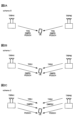
- 1A and 1B are diagrams illustrating an example of communication between a mobile and a transmission point (eg, RRH).
- 2A-2C are diagrams showing examples of schemes 0-2 for SFN.
- 3A and 3B are diagrams showing an example of Scheme 1.
- FIG. 4A-4C are diagrams illustrating an example of a Doppler precompensation scheme.
- FIG. 5 is a diagram illustrating an example of simultaneous beam update across multiple CCs.
- 6A and 6B are diagrams showing an example of a common beam.
- FIG. 7 shows the Rel. 16 is a diagram showing an example of MAC CE defined in V.16.
- FIG. 8 shows the Rel. 16 is a diagram showing another example of MAC CE defined in X.16.
- FIG. 9 shows the Rel.
- FIG. 16 is a diagram showing another example of MAC CE defined in X.16.
- 10A and 10B are diagrams showing an example of joint/separate TCI state indications.
- FIG. 11 is a diagram illustrating an example of timing until application of the indicated TCI state.
- 12A and 12B are diagrams showing examples of beam pointing method 1 and beam pointing method 2, respectively.
- 13A and 13B are diagrams showing examples of TCI fields included in DCI.
- 14A and 14B are diagrams illustrating an example of how to activate/indicate a joint TCI state and how to activate/indicate a separate TCI state, respectively.
- FIG. 15 is a diagram showing an example of switches in correspondence with TCI states.
- FIG. 16 is a diagram illustrating an example of correspondence regarding TCI states according to the first embodiment.
- FIG. 17 is a diagram illustrating another example of correspondence regarding TCI states according to the first embodiment.
- 18A and 18B are diagrams illustrating an example of application of TCI states in transmission and reception using multi-TRP.
- 19A and 19B are diagrams illustrating an example of how to apply the indicated TCI state.
- 20A to 20D are diagrams showing an example of PUSCH and TCI state mapping.
- 21A to 21C are diagrams illustrating an example of PUCCH and TCI state mapping.
- FIG. 22 is a diagram showing an example of BAT according to Embodiment 3-2-2.
- FIG. 23 is a diagram showing an example of BAT according to Embodiment 3-2-3.
- FIG. 24 is a diagram illustrating an example of TCI state activation according to the fourth embodiment.
- FIGS. 25A and 25B are diagrams illustrating another example of TCI state activation according to the fourth embodiment.
- FIGS. 26A and 26B are diagrams showing correspondences regarding TCI states according to the fourth embodiment.
- FIG. 27 is a diagram showing an example of BAT according to the fifth embodiment.
- FIG. 28 is a diagram showing another example of BAT according to the fifth embodiment.
- FIG. 29 is a diagram showing an example of the configuration of MAC CE according to Embodiment 6-1.
- FIG. 30 is a diagram showing an example of the configuration of MAC CE according to Embodiment 6-2-1.
- FIG. 31 is a diagram showing an example of the configuration of MAC CE according to Embodiment 6-2-3.
- FIG. 32 is a diagram showing an example of the configuration of MAC CE according to Embodiments 6-2-4/6-2-5.
- FIG. 33 is a diagram showing an example of the configuration of MAC CE according to Embodiment 6-2-6.
- 34A and 34B are diagrams showing an example of the configuration of MAC CE according to Embodiment 6-2-7.
- FIG. 35 is a diagram showing an example of the configuration of MAC CE according to Embodiment 6-2-8.
- FIG. 36 is a diagram showing another example of the MAC CE configuration according to Embodiment 6-2-8.
- FIG. 37 is a diagram illustrating an example of a schematic configuration of a wireless communication system according to an embodiment;
- FIG. 38 is a diagram illustrating an example of the configuration of a base station according to one embodiment.
- FIG. 39 is a diagram illustrating an example of the configuration of a user terminal according to an embodiment
- FIG. 40 is a diagram illustrating an example of hardware configurations of a base station and a user terminal according to an embodiment.
- FIG. 41 is a diagram illustrating an example of a vehicle according to one embodiment;
- the reception processing e.g., reception, demapping, demodulation, decoding
- transmission processing e.g, at least one of transmission, mapping, precoding, modulation, encoding
- the TCI state may represent those that apply to downlink signals/channels.
- the equivalent of TCI conditions applied to uplink signals/channels may be expressed as spatial relations.
- the TCI state is information about the pseudo-co-location (QCL) of signals/channels, and may be called spatial reception parameters, spatial relation information, or the like.
- the TCI state may be set in the UE on a channel-by-channel or signal-by-signal basis.
- QCL is an index that indicates the statistical properties of a signal/channel. For example, when one signal/channel and another signal/channel have a QCL relationship, Doppler shift, Doppler spread, average delay ), delay spread, spatial parameters (e.g., spatial Rx parameter) are identical (QCL with respect to at least one of these). You may
- the spatial reception parameters may correspond to the reception beams of the UE (eg, reception analog beams), and the beams may be specified based on the spatial QCL.
- QCL or at least one element of QCL in the present disclosure may be read as sQCL (spatial QCL).
- QCL types A plurality of types (QCL types) may be defined for the QCL.
- QCL types AD may be provided with different parameters (or parameter sets) that can be assumed to be the same, and the parameters (which may be referred to as QCL parameters) are shown below:
- QCL type A QCL-A
- QCL type B QCL-B
- QCL type C QCL-C
- QCL-D Spatial reception parameters.
- CORESET Control Resource Set
- QCL QCL type D
- a UE may determine at least one of a transmit beam (Tx beam) and a receive beam (Rx beam) for a signal/channel based on the TCI conditions or QCL assumptions of that signal/channel.
- Tx beam transmit beam
- Rx beam receive beam
- the TCI state may be, for example, information about the QCL between the channel of interest (in other words, the reference signal (RS) for the channel) and another signal (for example, another RS). .
- the TCI state may be set (indicated) by higher layer signaling, physical layer signaling or a combination thereof.
- Physical layer signaling may be, for example, downlink control information (DCI).
- DCI downlink control information
- Channels for which TCI states or spatial relationships are set are, for example, Physical Downlink Shared Channel (PDSCH), Physical Downlink Control Channel (PDCCH), Physical Uplink Shared Channel It may be at least one of a channel (PUSCH)) and an uplink control channel (Physical Uplink Control Channel (PUCCH)).
- PDSCH Physical Downlink Shared Channel
- PDCCH Physical Uplink Control Channel
- RSs that have a QCL relationship with the channel are, for example, a synchronization signal block (SSB), a channel state information reference signal (CSI-RS), a measurement reference signal (Sounding It may be at least one of a reference signal (SRS)), a tracking CSI-RS (also called a tracking reference signal (TRS)), and a QCL detection reference signal (also called a QRS).
- SSB synchronization signal block
- CSI-RS channel state information reference signal
- Sounding It may be at least one of a reference signal (SRS)), a tracking CSI-RS (also called a tracking reference signal (TRS)), and a QCL detection reference signal (also called a QRS).
- SRS reference signal
- TRS tracking reference signal
- QRS QCL detection reference signal
- An SSB is a signal block that includes at least one of a Primary Synchronization Signal (PSS), a Secondary Synchronization Signal (SSS), and a Physical Broadcast Channel (PBCH).
- PSS Primary Synchronization Signal
- SSS Secondary Synchronization Signal
- PBCH Physical Broadcast Channel
- An SSB may also be called an SS/PBCH block.
- a QCL type X RS in a TCI state may mean an RS that has a QCL type X relationship with (the DMRS of) a certain channel/signal, and this RS is called a QCL type X QCL source in that TCI state.
- QCL type A RS is always set for PDCCH and PDSCH, and QCL type D RS may be additionally set. Since it is difficult to estimate Doppler shift, delay, etc. by receiving DMRS one-shot, QCL type A RS is used to improve channel estimation accuracy. QCL type D RS is used for receive beam determination during DMRS reception.
- TRS 1-1, 1-2, 1-3, 1-4 are transmitted, and TRS 1-1 is notified as QCL type C/D RS depending on the TCI status of PDSCH.
- the UE can use the information obtained from the past periodic TRS1-1 reception/measurement results for PDSCH DMRS reception/channel estimation.
- the PDSCH QCL source is TRS1-1 and the QCL target is the PDSCH DMRS.
- the PDSCH may be scheduled on DCI with the TCI field.
- the TCI state for PDSCH is indicated by the TCI field.
- the TCI field of DCI format 1-1 is 3 bits
- the TCI field of DCI format 1-2 is 3 bits maximum.
- the UE In RRC connected mode, if for a CORESET that schedules the PDSCH, if the first TCI in DCI information element (higher layer parameter tci-PresentInDCI) is set to 'enabled', the UE shall Assume that the TCI field is present in DCI format 1_1 of the transmitted PDCCH.
- DCI information element higher layer parameter tci-PresentInDCI
- the UE will set the DCI format of the PDSCH transmitted in that CORESET 1_2, there is a TCI field with the DCI field size indicated in the second DCI-in-TCI information element.
- the PDSCH may be scheduled on DCI with no TCI field.
- the DCI format of the DCI is DCI format 1_0 or DCI format 1_1/1_2 in the case where the TCI information element in DCI (higher layer parameter tci-PresentInDCI or tci-PresentInDCI-1-2) is not set (enabled).
- the UE assumes that the TCI state or QCL assumption for the PDSCH is the same as the TCI state or QCL assumption for the CORESET (e.g. scheduling DCI) (default TCI state) .
- the TCI information element in DCI (higher layer parameters tci-PresentInDCI and tci-PresentInDCI-1-2) is set to "enabled", and when the TCI information element in DCI is not set .
- the threshold timeDurationForQCL
- the PDSCH TCI state (default TCI state) is the TCI state of the lowest CORESET ID in the most recent slot in the active DL BWP of that CC (for a particular UL signal) may be Otherwise, the TCI state of the PDSCH (default TCI state) may be the TCI state of the lowest TCI state ID of the PDSCH in the active DL BWP of the scheduled CC.
- Rel. 15 requires separate MAC CEs for activation/deactivation of PUCCH spatial relations and MAC CEs for activation/deactivation of SRS spatial relations.
- the PUSCH spatial relationship follows the SRS spatial relationship.
- At least one of MAC CE for activation/deactivation of PUCCH spatial relationship and MAC CE for activation/deactivation of SRS spatial relationship may not be used.
- both the spatial relationship and PL-RS for PUCCH are not configured (applicable condition, second condition)
- default assumption of spatial relationship and PL-RS for PUCCH (default spatial relationship and default PL-RS) applies.
- both the spatial relationship and PL-RS for SRS (SRS resource for SRS or SRS resource corresponding to SRI in DCI format 0_1 that schedules PUSCH) are not configured (applicable condition, second condition)
- the default assumption of spatial relationship and PL-RS (default spatial relationship and default PL-RS) is applied for PUSCH and SRS scheduled by DCI format 0_1.
- the default spatial relationship and default PL-RS are assumed to be the TCI state or QCL of the CORESET with the lowest CORESET ID in that active DL BWP. There may be. If no CORESET is set in the active DL BWP on that CC, the default spatial relationship and default PL-RS may be the active TCI state with the lowest ID of the PDSCH in that active DL BWP.
- the spatial relationship of PUSCHs scheduled by DCI format 0_0 follows the spatial relationship of the PUCCH resource with the lowest PUCCH resource ID among the active spatial relationships of PUCCHs on the same CC.
- the network needs to update the PUCCH spatial relationship on all SCells even if no PUCCH is transmitted on the SCell.
- the conditions for applying the default spatial relationship/default PL-RS for SRS may include that the default beam path loss enablement information element for SRS (higher layer parameter enableDefaultBeamPlForSRS) is set to valid.
- the conditions for applying the default spatial relationship/default PL-RS for PUCCH may include that the enable default beam path loss information element for PUCCH (higher layer parameter enableDefaultBeamPlForPUCCH) is set to Enabled.
- the application condition of the default spatial relationship/default PL-RS for PUSCH scheduled by DCI format 0_0 is that the default beam path loss enable information element for PUSCH scheduled by DCI format 0_0 (higher layer parameter enableDefaultBeamPlForPUSCH0_0) is set to valid.
- RRC parameters (enable default beam PL for PUCCH (enableDefaultBeamPL-ForPUCCH), enable default beam PL for PUSCH (enableDefaultBeamPL-ForPUSCH0_0), or SRS If the parameter to enable default beam PL for (enableDefaultBeamPL-ForSRS) is set and no spatial relationship or PL-RS is configured, the UE applies the default spatial relationship/PL-RS.
- the above thresholds are time duration for QCL, "timeDurationForQCL”, “Threshold”, “Threshold for offset between a DCI indicating a TCI state and a PDSCH scheduled by the DCI”, “Threshold-Sched-Offset”, “ beamSwitchTiming”, schedule offset threshold, scheduling offset threshold, etc.
- the threshold may be reported by the UE as a UE capability (per subcarrier spacing).
- the offset (scheduling offset) between the reception of the DL DCI and the corresponding PDSCH is smaller than the threshold timeDurationForQCL, and at least one TCI state set for the serving cell of the scheduled PDSCH is "QCL type D" and if the UE is configured with two default TCI enable information elements (enableTwoDefaultTCIStates-r16) and at least one TCI codepoint (the codepoint of the TCI field in the DL DCI) indicates two TCI states, the UE is the PDSCH of the serving cell or the DMRS port of the PDSCH transmission occasion is RS and QCL with respect to the QCL parameters associated with the two TCI states corresponding to the lowest of the TCI codepoints containing the two different TCI states ( quasi co-located) (2 default QCL assumption decision rule). 2 default TCI enablement information element specifies the Rel. 16 operation is enabled.
- PDSCH default TCI states in 2015/16 a default TCI state for single TRP, a default TCI state for multi-TRP based on multi-DCI, and a default TCI state for multi-TRP based on single DCI are specified.
- Default TCI state for aperiodic CSI-RS (A(aperiodic)-CSI-RS) on 2015/16: default TCI state for single TRP, default TCI state for multi-TRP based on multi-DCI, based on single DCI A default TCI state for multi-TRP is specified.
- the default spatial relationship and default PL-RS are specified for PUSCH/PUCCH/SRS respectively.
- Multi-TRP In NR, one or more transmission/reception points (Transmission/Reception Points (TRP)) (multi TRP (multi TRP (MTRP))) uses one or more panels (multi-panel) to the UE DL transmission is under consideration. It is also being considered that the UE uses one or more panels to perform UL transmissions for one or more TRPs.
- TRP Transmission/Reception Points
- MTRP multi TRP
- a plurality of TRPs may correspond to the same cell identifier (cell identifier (ID)) or may correspond to different cell IDs.
- the cell ID may be a physical cell ID or a virtual cell ID.
- Multi-TRPs may be connected by ideal/non-ideal backhauls to exchange information, data, and the like.
- Different codewords (CW) and different layers may be transmitted from each TRP of the multi-TRP.
- Non-Coherent Joint Transmission NCJT may be used as one form of multi-TRP transmission.
- TRP#1 modulate-maps a first codeword and layer-maps a first number of layers (e.g., two layers) with a first precoding to transmit a first PDSCH.
- TRP#2 also modulates and layer-maps a second codeword to transmit a second PDSCH with a second number of layers (eg, 2 layers) with a second precoding.
- multiple PDSCHs to be NCJTed may be defined as partially or completely overlapping in at least one of the time and frequency domains. That is, the first PDSCH from the first TRP and the second PDSCH from the second TRP may overlap at least one of time and frequency resources.
- first PDSCH and second PDSCH are not quasi-co-located (QCL).
- Reception of multiple PDSCHs may be translated as simultaneous reception of PDSCHs that are not of a certain QCL type (eg, QCL type D).
- Multiple PDSCHs from multiple TRPs may be scheduled using one DCI (single DCI, single PDCCH) (single master mode, based on single DCI Multi-TRP (single-DCI based multi-TRP)).
- Multiple PDSCHs from multi-TRP may be scheduled using multiple DCIs (multi-DCI, multiple PDCCH) (multi-master mode, multi-DCI based multi-TRP (multiple PDCCH)). TRP)).
- PDSCH transport block (TB) or codeword (CW) repetition across multi-TRPs.
- repetition schemes URLLC schemes, eg schemes 1, 2a, 2b, 3, 4
- SDM space division multiplexed
- FDM frequency division multiplexed
- RV redundancy version
- the RVs may be the same or different for the multi-TRPs.
- multiple PDSCHs from multiple TRPs are time division multiplexed (TDM).
- TDM time division multiplexed
- multiple PDSCHs from multiple TRPs are transmitted within one slot.
- multiple PDSCHs from multiple TRPs are transmitted in different slots.
- one control resource set (CORESET) in PDCCH configuration information (PDCCH-Config) may correspond to one TRP.
- the UE may determine multi-TRP based on multi-DCI if at least one of the following conditions 1 and 2 is met: In this case, TRP may be read as a CORESET pool index.
- TRP may be read as a CORESET pool index.
- a CORESET pool index of 1 is set.
- Two different values (eg, 0 and 1) of the CORESET pool index are set.
- the UE may determine multi-TRP based on single DCI if the following conditions are met: In this case, two TRPs may be translated into two TCI states indicated by MAC CE/DCI. [conditions] "Enhanced TCI States Activation/Deactivation for UE- specific PDSCH MAC CE)” is used.
- DCI for common beam indication may be a UE-specific DCI format (e.g., DL DCI format (e.g., 1_1, 1_2), UL DCI format (e.g., 0_1, 0_2)), or a UE group common (UE-group common) DCI format.
- DL DCI format e.g., 1_1, 1_2
- UL DCI format e.g., 0_1, 0_2
- UE group common UE-group common
- multi-TRP PDCCH For the reliability of multi-TRP PDCCHs based on non-single frequency networks (SFN), the following considerations 1 to 3 are considered.
- Consideration 1 Coding/rate matching is based on one repetition, and the same coded bits are repeated in other repetitions.
- Consideration 2 Each iteration has the same number of control channel elements (CCEs), the same coded bits, and corresponds to the same DCI payload.
- CCEs control channel elements
- Two or more PDCCH candidates are explicitly linked together. UE knows the link before decoding.
- Two sets of PDCCH candidates (within a given search space (SS) set) are associated with two TCI states of CORESET, respectively.
- same CORESET, same SS set, PDCCH repetitions in different monitoring occasions are used.
- Two sets of PDCCH candidates are associated with two SS sets respectively. Both SS sets are associated with a CORESET and each SS set is associated with only one TCI state of that CORESET. Here the same CORESET, two SS sets, is used.
- CORESETPoolIndex (which may be called TRP Info) is set for one CORESET.
- SFN single frequency network
- RRC signaling/MAC CE higher layer signaling
- each search space set is associated with the corresponding CORESET (enhancement 2 ).
- the two search space sets may be associated with the same or different CORESETs.
- one (maximum one) TCI state can be set/activated in higher layer signaling (RRC signaling/MAC CE).
- two search space sets are associated with different CORESETs with different TCI states, it may imply a repeated transmission of multi-TRP. If two search space sets are associated with the same CORESET (with the same TCI state CORESET), it may imply repeated transmission of a single TRP.
- HST High speed trains
- Large antennas transmit into/out of tunnels.
- the transmission power of a large antenna is about 1 to 5W.
- the transmission power of a small antenna is approximately 250 mW.
- Multiple small antennas transmit and receive points
- SFN single frequency network
- All small antennas within the SFN transmit the same signal at the same time on the same PRB. It is assumed that a terminal transmits and receives to one base station. In practice, multiple transmit/receive points transmit the same DL signal.
- transmission/reception points in units of several kilometers form one cell. Handover is performed when crossing cells. As a result, handover frequency can be reduced.
- NR In NR, it is transmitted from a transmission point (for example, RRH) in order to communicate with a terminal (hereinafter also referred to as UE) included in a mobile object (HST (high speed train)) such as a train that moves at high speed It is envisaged to use beams.
- HST high speed train
- Existing systems eg, Rel. 15 support the transmission of unidirectional beams from RRHs to communicate with mobile units (see FIG. 1A).
- FIG. 1A shows a case where RRHs are installed along the moving route (or moving direction, traveling direction, or traveling route) of the moving body, and beams are formed from each RRH toward the traveling direction of the moving body.
- An RRH that forms a beam in one direction may be called a uni-directional RRH (uni-directional RRH).
- the mobile receives a negative Doppler shift (-fD) from each RRH.
- the beam is not limited to this, and the beam may be formed in the opposite direction to the moving direction. Beams may be formed in any direction regardless of .
- multiple (eg, two or more) beams are transmitted from the RRH.
- beams are formed both in the traveling direction of the moving object and in the opposite direction (see FIG. 1B).
- FIG. 1B shows a case where RRHs are installed along the movement path of the moving object, and beams are formed from each RRH in both the traveling direction side and the opposite direction side of the traveling direction of the moving object.
- An RRH that forms beams in multiple directions may be called a bidirectional RRH (bi-directional RRH).
- the UE communicates in the same way as in single TRP.
- multiple TRPs (with the same cell ID) can be transmitted.
- the mobile will have high power from a negative Doppler shifted signal halfway between the two RRHs. switch to a signal that has undergone a positive Doppler shift.
- the maximum change width of the Doppler shift that requires correction is a change from -fD to +fD, which is double that of the unidirectional RRH.
- the positive Doppler shift may be read as information on the positive Doppler shift, positive (positive) direction Doppler shift, and positive (positive) direction Doppler information.
- the negative Doppler shift may be read as information about the negative Doppler shift, negative Doppler shift, or negative Doppler information.
- the tracking reference signal (TRS), DMRS and PDSCH are commonly transmitted (using the same time and same frequency resources) on two TRPs (RRH) (regular SFN, transparent transparent SFN, HST-SFN).
- the PDSCH has one TCI state because the UE receives the DL channel/signal for a single TRP.
- RRC parameters are defined to distinguish between transmissions utilizing a single TRP and transmissions utilizing an SFN.
- the UE may distinguish between reception of DL channels/signals for single TRP and reception of PDSCH assuming SFN based on this RRC parameter when reporting the corresponding UE capability information.
- the UE may transmit and receive using SFN assuming a single TRP.
- TRSs are transmitted TRP-specifically (using different time/frequency resources depending on the TRP).
- TRS1 is transmitted from TRP#1
- TRS2 is transmitted from TRP#2.
- TRS and DMRS are transmitted TRP-specifically.
- TRS1 and DMRS1 are transmitted from TRP#1
- TRS2 and DMRS2 are transmitted from TRP#2.
- Schemes 1 and 2 suppress abrupt changes in Doppler shift compared to scheme 0, and can properly estimate/compensate for the Doppler shift.
- the maximum throughput of scheme 2 is lower than that of scheme 1 because the DMRS of scheme 2 is increased more than the DMRS of scheme 1 .
- the UE switches between single TRP and SFN based on higher layer signaling (RRC information element/MAC CE).
- the UE may switch scheme 1/scheme 2/NW pre-compensation scheme based on higher layer signaling (RRC information element/MAC CE).
- RRC information element/MAC CE higher layer signaling
- the TRPs (TRP#0, #2, . ).
- the TRPs (TRP#1, #3, . . . ) that transmit DL signals in the traveling direction of the HST transmit the second TRS (TRS arriving after the HST) on the same time and frequency resource (SFN).
- the first TRS and the second TRS may be transmitted/received using different frequency resources.
- TRS1-1 to 1-4 are transmitted as the first TRS, and TRS2-1 to 2-4 are transmitted as the second TRS.
- 64 beams and 64 time resources are used to transmit the first TRS, and 64 beams and 64 time resources are used to transmit the second TRS.
- the beams of the first TRS and the beams of the second TRS are considered equal (equal QCL type DRS). Resource utilization efficiency can be improved by multiplexing the first TRS and the second TRS on the same time resource and different frequency resources.
- RRHs #0-#7 are arranged along the movement route of the HST.
- RRH#0-#3 and RRH#4-#7 are connected to baseband units (BBU) #0 and #1, respectively.
- BBU baseband units
- Each RRH is a bi-directional RRH, and forms beams using each transmission/reception point (TRP) in both the travel direction and the reverse direction of the movement route.
- the base station uses a Doppler pre-compensation (correction) scheme (Pre-Doppler Compensation scheme, Doppler pre-Compensation scheme, Network (NW) pre-compensation scheme (NW pre-compensation scheme, HST NW pre-compensation scheme), TRP pre-compensation scheme, TRP-based pre-compensation scheme) are being considered.
- Doppler precompensation scheme may be a combination of Scheme 1 and precompensation for Doppler shift by the base station.
- the TRP that forms the beam on the traveling direction side of the movement path and the TRP that forms the beam on the opposite direction side of the movement path, after performing Doppler correction, to the UE in the HST Perform transmission of DL signals/channels.
- TRP#2n-1 provides positive Doppler correction
- TRP#2n provides negative Doppler correction to reduce the effects of Doppler shifts in the UE's signal/channel reception (Fig. 4C).
- the TCI field (TCI state field) is being considered to dynamically switch between single TRP and SFN.
- TCI state field For example, using RRC information element / MAC CE (for example, Enhanced TCI States Activation / Deactivation for UE-specific PDSCH MAC CE) / DCI (TCI field), each TCI code point (TCI field code point, DCI code point) , one or two TCI states are set/indicated.
- a UE may decide to receive a single TRP PDSCH when configured/indicated to one TCI state.
- the UE may decide to receive the SFN PDSCH with multi-TRP when configured/indicated with two TCI states.
- one MAC CE can update the beam index (TCI state) of multiple CCs.
- a UE can be configured by RRC with up to two applicable CC lists (eg, applicable-CC-list). If two applicable CC lists are configured, the two applicable CC lists may correspond to intra-band CA in FR1 and intra-band CA in FR2, respectively.
- PDCCH TCI state activation MAC CE activates the TCI state associated with the same CORESET ID on all BWP/CCs in the applicable CC list.
- PDSCH TCI state activation MAC CE activates TCI state on all BWP/CCs in the applicable CC list.
- A-SRS/SP-SRS spatial relationship activation MAC CE activates the spatial relationship associated with the same SRS resource ID on all BWP/CCs in the applicable CC list.
- the UE is configured with an applicable CC list indicating CC #0, #1, #2, #3 and a list indicating 64 TCI states for each CC's CORESET or PDSCH.
- the UE is configured with an applicable CC list indicating CC #0, #1, #2, #3 and a list indicating 64 TCI states for each CC's CORESET or PDSCH.
- the corresponding TCI states are activated in CC#1, #2, and #3.
- the UE may base procedure A below.
- the UE issues an activation command to map up to 8 TCI states to codepoints in the DCI field (TCI field) within one CC/DL BWP or within one set of CC/BWPs. receive. If a set of TCI state IDs is activated for a set of CC/DL BWPs, where the applicable list of CCs is determined by the CCs indicated in the activation command, and the same The set applies to all DL BWPs within the indicated CC.
- One set of TCI state IDs can be activated for one set of CC/DL BWPs.
- the UE may base procedure B below.
- the simultaneous TCI update list (simultaneousTCI-UpdateList-r16 and simultaneousTCI-UpdateListSecond-r16)
- the simultaneous TCI cell list (simultaneousTCI- CellList)
- the UE has an index p in all configured DL BWPs of all configured cells in one list determined from the serving cell index provided by the MAC CE command.
- CORESET apply the antenna port quasi co-location (QCL) provided by the TCI state with the same activated TCI state ID value.
- QCL quasi co-location
- a concurrent TCI cell list may be provided for concurrent TCI state activation.
- the UE may base procedure C below.
- spatial relation information for SP or AP-SRS resource set by SRS resource information element (higher layer parameter SRS-Resource) is activated/updated by MAC CE.
- the CC's applicable list is indicated by the simultaneous spatial update list (higher layer parameter simultaneousSpatial-UpdateList-r16 or simultaneousSpatial-UpdateListSecond-r16), and in all BWPs within the indicated CC, the same SRS resource
- the spatial relationship information is applied to the SP or AP-SRS resource with ID.
- a simultaneous TCI cell list (simultaneousTCI-CellList), a simultaneous TCI update list (at least one of simultaneousTCI-UpdateList1-r16 and simultaneousTCI-UpdateList2-r16) are serving cells whose TCI relationships can be updated simultaneously using MAC CE. is a list of simultaneousTCI-UpdateList1-r16 and simultaneousTCI-UpdateList2-r16 do not contain the same serving cell.
- a simultaneous spatial update list (at least one of the upper layer parameters simultaneousSpatial-UpdatedList1-r16 and simultaneousSpatial-UpdatedList2-r16) is a list of serving cells whose spatial relationships can be updated simultaneously using MAC CE.
- simultaneousSpatial-UpdatedList1-r16 and simultaneousSpatial-UpdatedList2-r16 do not contain the same serving cell.
- the simultaneous TCI update list and the simultaneous spatial update list are set by RRC
- the CORESET pool index of the CORESET is set by RRC
- the TCI codepoints mapped to TCI states are indicated by MAC CE.
- the unified TCI framework allows UL and DL channels to be controlled by a common framework.
- the unified TCI framework is Rel. Instead of defining TCI conditions or spatial relationships per channel as in 15, a common beam (common TCI condition) may be indicated and applied to all channels in the UL and DL, or for the UL A common beam may be applied to all channels in the UL and a common beam for the DL may be applied to all channels in the DL.
- One common beam for both DL and UL, or a common beam for DL and a common beam for UL (two common beams in total) are being considered.
- the UE may assume the same TCI state (joint TCI state, joint TCI pool, joint common TCI pool, joint TCI state set) for UL and DL.
- the UE assumes different TCI states for each of UL and DL (separate TCI state, separate TCI pool, UL separate TCI pool and DL separate TCI pool, separate common TCI pool, UL common TCI pool and DL common TCI pool).
- the UL and DL default beams may be aligned by MAC CE-based beam management (MAC CE level beam designation).
- the PDSCH default TCI state may be updated to match the default UL beam (spatial relationship).
- DCI-based beam management may indicate common beam/unified TCI state from the same TCI pool for both UL and DL (joint common TCI pool, joint TCI pool, set).
- X (>1) TCI states may be activated by MAC CE.
- the UL/DL DCI may select 1 out of X active TCI states.
- the selected TCI state may apply to both UL and DL channels/RS.
- the TCI pool (set) may be a plurality of TCI states set by RRC parameters, or a plurality of TCI states activated by MAC CE (active TCI state, active TCI pool, set).
- Each TCI state may be a QCL type A/D RS.
- SSB, CSI-RS, or SRS may be set as QCL type A/D RS.
- the number of TCI states corresponding to each of one or more TRPs may be defined. For example, the number N ( ⁇ 1) of TCI states (UL TCI states) applied to UL channels/RSs and the number M ( ⁇ 1) of TCI states (DL TCI states) applied to DL channels/RSs and may be defined. At least one of N and M may be signaled/configured/indicated to the UE via higher layer signaling/physical layer signaling.
- the UE has X UL and DL common TCI states (corresponding to X TRPs) (joint TCI status) is signaled/set/indicated.
- N X (X is an arbitrary integer)
- X (X TRPs) and Y DL TCI states are signaled/set/indicated.
- the UL TCI state and the DL TCI state may mean a TCI state common to UL and DL (i.e., joint TCI state), or may mean a TCI state for each of UL and DL (i.e., separate TCI state).
- the UE is notified/configured/instructed of a TCI state common to multiple (two) ULs and DLs for multiple (two) TRPs (joint TCI state for multiple TRPs).
- multiple (two) UL TCI states and multiple (two) DL TCI states for multiple (two) TRPs State may mean signaled/set/indicated (separate TCI state for multiple TRPs).
- the UE may use the two configured/indicated TCI states as the UL TCI state, and use one of the two configured/indicated TCI states as the DL TCI state.
- N and M are 1 or 2
- N and M may be 3 or more, and N and M may be different.
- the case of M>1/N>1 may indicate at least one of TCI status indications for multiple TRPs and multiple TCI status indications for inter-band CA.
- the RRC parameters configure multiple TCI states for both DL and UL.
- the MAC CE may activate multiple TCI states out of multiple configured TCI states.
- a DCI may indicate one of multiple TCI states that have been activated.
- DCI may be UL/DL DCI.
- the indicated TCI conditions may apply to at least one (or all) of the UL/DL channels/RSs.
- One DCI may indicate both UL TCI and DL TCI.
- one point may be one TCI state that applies to both UL and DL, or two TCI states that apply to UL and DL respectively.
- At least one of the multiple TCI states set by the RRC parameters and the multiple TCI states activated by the MAC CE may be called a TCI pool (common TCI pool, joint TCI pool, TCI state pool). good.
- Multiple TCI states activated by a MAC CE may be called an active TCI pool (active common TCI pool).
- RRC parameters higher layer parameters that configure multiple TCI states
- configuration information that configures multiple TCI states, or simply "configuration information.”
- to indicate one of the plurality of TCI states using the DCI may be receiving indication information indicating one of the plurality of TCI states included in the DCI. , it may simply be to receive "instruction information”.
- the RRC parameters configure multiple TCI states (joint common TCI pools) for both DL and UL.
- the MAC CE may activate multiple TCI states (active TCI pool) out of multiple configured TCI states. Separate active TCI pools for each of the UL and DL may be configured/activated.
- a DL DCI or a new DCI format may select (indicate) one or more (eg, one) TCI states.
- the selected TCI state may be applied to one or more (or all) DL channels/RS.
- the DL channel may be PDCCH/PDSCH/CSI-RS.
- the UE is Rel.
- a 16 TCI state operation (TCI framework) may be used to determine the TCI state for each channel/RS in the DL.
- a UL DCI or new DCI format may select (indicate) one or more (eg, one) TCI states.
- the selected TCI state may be applied to one or more (or all) UL channels/RS.
- the UL channel may be PUSCH/SRS/PUCCH.
- different DCIs may indicate UL TCI and DL DCI separately.
- the existing DCI format 1_1/1_2 may be used to indicate common TCI status.
- the DCI format that indicates the TCI status may be a specific DCI format.
- the particular DCI format may be DCI format 1_1/1_2 (defined in Rel. 15/16/17).
- the DCI format (DCI format 1_1/1_2) indicating the TCI state may be a DCI format without DL assignment.
- a DCI format without a DL assignment a DCI format that does not schedule PDSCH (DCI format 1_1/1_2), a DCI format that does not include one or more specific fields (DCI format 1_1/1_2), one or more A DCI format in which a specific field is set to a fixed value (DCI format 1_1/1_2) may be read interchangeably.
- the specific fields are: TCI field, DCI format identifier field, carrier indicator field, bandwidth part (BWP) indicator field , Time Domain Resource Assignment (TDRA) field, Downlink Assignment Index (DAI) field (if set), Transmission Power Control (for scheduled PUCCH) (TPC)) command field, PUCCH resource indicator field, and PDSCH-to-HARQ feedback timing indicator field (if present), fields other than .
- the particular field may be set as a reserved field or may be ignored.
- the specific fields are Redundancy Version (RV) field, Modulation and Coding Scheme (MCS) field, New Data Indicator field, and Frequency Domain Resource Assignment (FDRA) field.
- RV Redundancy Version
- MCS Modulation and Coding Scheme
- FDRA Frequency Domain Resource Assignment
- All RV fields may be set to 1.
- the MCS field may be set to all ones.
- the NDI field may be set to 0.
- Type 0 FDRA fields may be set to all zeros.
- Type 1 FDRA field may be set to all ones.
- the FDRA field for dynamic switching (higher layer parameter dynamicSwitch) may be set to all zeros.
- a common TCI framework may have separate TCI states for DL and UL.
- MAC CE TCI States Activation/Deactivation for UE-specific PDSCH MAC CE
- the relevant MAC CE is identified by a MAC subheader with a Logical Channel ID (LCID).
- LCID Logical Channel ID
- the MAC CE may be used in an environment that uses a single TRP or multi-TRP based on multi-DCI.
- the MAC CE includes a Serving Cell ID field, a BWP ID field, a field (Ti) for indicating activation/deactivation of the TCI state, and a CORESET pool ID (CORESET Pool ID) field.
- a Serving Cell ID field a BWP ID field
- a CORESET pool ID CORESET Pool ID
- the serving cell ID field may be a field for indicating the serving cell to which the MAC CE is applied.
- the BWP ID field may be a field for indicating the DL BWP to which the MAC CE is applied.
- the CORESET pool ID field the correspondence (mapping) between the activated TCI state and the TCI field code point indicated by the DCI set in the field Ti (DCI TCI code point) is set by the CORESET pool ID. It may be a field indicating that it is unique to the specified ControlResourceSetId.
- MAC CE Enhanced TCI States Activation/Deactivation for UE-specific PDSCH MAC CE
- UE-specific PDSCH TCI state activation/deactivation see FIG. 8
- the relevant MAC CE is identified by a MAC PDU subheader with an eLCID.
- This MAC CE may be used in an environment that uses multiple TRPs based on a single DCI.
- the MAC CE contains a Serving Cell ID field, a BWP ID field, a field for indicating the TCI state identified by the TCI-State ID (TCI state IDi,j (i is an integer from 0 to N, j is 1 or 2)), a field (Ci) indicating whether TCI state IDi,2 is present in the corresponding octet, and a reserved bit field (R, set to 0).
- TCI state IDi,j a field for indicating the TCI state identified by the TCI-State ID
- Ci indicating whether TCI state IDi,2 is present in the corresponding octet
- R reserved bit field
- i may correspond to the codepoint index of the TCI field indicated by the DCI.
- TCI state IDi,j may indicate the j-th TCI state of the i-th TCI field codepoint.
- MAC CE TCI State Indication for UE-specific PDCCH MAC CE
- UE-specific PDCCH/CORESET TCI state activation/deactivation see FIG. 9
- the relevant MAC CE is identified by a MAC subheader with LCID.
- the MAC CE contains a Serving Cell ID field, a field indicating the CORESET (CORESET ID) indicating the TCI state, and a field for indicating the TCI state applicable to the CORESET identified by the CORESET ID. (TCI state ID) may be included.
- Beam application time (BAT)) Rel Beam application time (BAT) Rel.
- BAT beam application time
- the first slot to apply the indicated TCI is at least Y symbols after the last symbol of the acknowledgment (ACK) for joint or separate DL/UL beam indication. It is considered that the first slot to apply the indicated TCI is at least Y symbols after the last symbol of the ACK/negative acknowledgment (NACK) for joint or separate DL/UL beam indications.
- the Y symbol may be set by the base station based on the UE capabilities reported by the UE. The UE capabilities may be reported on a symbol-by-symbol basis.
- the ACK may be an ACK for the PDSCH scheduled by the beam pointing DCI.
- PDSCH may not be scheduled by beam pointing DCI.
- the ACK in this case may be an ACK for the beam pointing DCI.
- At least one Y symbol per BWP/CC is configured in the UE for 17 DCI-based beam indications.
- the Y symbol values are also different, so there is a possibility that the application time will be different between multiple CCs.
- the application time of the beam pointing may follow any of options 1 to 3 below.
- [Option 1] Both the first slot and the Y symbol are determined on the carrier with the lowest SCS among the one or more carriers to which the beam pointing applies.
- [Option 2] Both the first slot and the Y symbol are determined on the carrier with the lowest SCS among the one or more carriers applying the beam pointing and the UL carrier carrying the ACK.
- the beam instruction application time (Y symbols) for CA may be determined on the carrier with the minimum SCS among the carriers to which the beam instruction is applied.
- Rel. 17 MAC CE-based beam indications (if only a single TCI codepoint is activated), the MAC CE activation Rel. 16 application timeline.
- the indicated TCI states with 17 TCI states may start to apply from the first slot that is at least Y symbols after the last symbol of that PUCCH.
- Y may be a higher layer parameter (eg, BeamAppTime_r17[symbol]). Both the first slot and the Y symbols may be determined on the carrier with the lowest SCS among the carriers to which beam pointing applies.
- the UE may, at a given moment, assume one indicated TCI state with Rel17 TCI states for DL and UL, or one indicated TCI (apart from DL) with Rel17 TCI state for UL. state can be assumed.
- X [ms] may be used instead of Y [symbol].
- the UE reports at least one of the following UE capabilities 1 and 2.
- UE Capability 1 Minimum application time per SCS (minimum value of Y symbols between the last symbol of PUCCH carrying an ACK and the first slot in which the beam is applied).
- UE Capability 2 Minimum time gap between the last symbol of the beam directed PDCCH (DCI) and the first slot where the beam applies. The gap between the last symbol of the beam pointing PDCCH (DCI) and the first slot where the beam applies may satisfy the UE capability (minimum time gap).
- UE capability 2 may be an existing UE capability (eg, timeDurationForQCL).
- the relationship between the beam designation and the channel/RS to which the beam applies may satisfy at least one of UE capabilities 1 and 2.
- the TCI state field (TCI field, up to 3 bit) to indicate one or more TCI states (common TCI state).
- FIG. 10A is a diagram showing an example of joint TCI state indication.
- one joint TCI state (DL/UL joint TCI state) may correspond to one code point of one TCI field.
- the UE may determine the TCI state to apply to the DL channel/signal and the UL channel/signal (DL/UL joint TCI state) based on the codepoints of the indicated TCI field.
- FIG. 10B is a diagram showing an example of separate TCI state indication.
- one or two TCI states correspond to codepoints in one TCI field.
- Each of the two TCI states may be a DL (separate) TCI state and a UL (separate) TCI state.
- the UE determines the TCI state to apply to DL channels/signals and the TCI state to apply to UL channels/signals based on the codepoints of the indicated TCI field. If the UE is informed of a TCI field codepoint corresponding to only one TCI state (eg, codepoint "000" in FIG. 10B), the UE may be notified of an unindicated TCI state (eg, codepoint "000” in FIG. 10B). 000” case, the UL TCI state) may continue/indicate the UL TCI state that applies until the notification.
- a timeline is considered for indication of TCI conditions (which may be referred to as "beam indication") to application of the indicated TCI conditions.
- the timing from reception of the beam indication to application of the TCI state (which may be referred to as beam application timing (BAT)) is the transmission of HARQ-ACK for the PDSCH scheduled with the DCI indicating the TCI state. It may be the timing (see FIG. 11) after a certain time (for example, after K symbols). The timing may be at least the first slot after a certain amount of time (eg, K symbols).
- BAT, K symbols, Y symbols, and X [ms] may be read interchangeably.
- the K may be determined based on higher layer signaling (RRC parameters) based on capability information reported by the UE (UE Capability Information, for example, "timeDurationForQCL-rel18").
- RRC parameters higher layer signaling
- UE Capability Information for example, "timeDurationForQCL-rel18"
- the BAT for a specific subcarrier interval may be set for multiple (for example, all) CCs/BWPs in which a common TCI state ID of a common TCI state in carrier aggregation (CA) is set.
- CA carrier aggregation
- the present inventors have developed a method for appropriately setting/indicating/applying the TCI state even when the TCI state is applied to multiple types of signals/channels in transmission/reception of signals/channels using multi-TRP. conceived.
- A/B/C and “at least one of A, B and C” may be read interchangeably.
- cell, serving cell, CC, carrier, BWP, DL BWP, UL BWP, active DL BWP, active UL BWP, band may be read interchangeably.
- indices, IDs, indicators, and resource IDs may be read interchangeably.
- sequences, lists, sets, groups, groups, clusters, subsets, etc. may be read interchangeably.
- supporting, controlling, controllable, operating, and capable of operating may be read interchangeably.
- configure, activate, update, indicate, enable, specify, and select may be read interchangeably.
- higher layer signaling may be, for example, Radio Resource Control (RRC) signaling, Medium Access Control (MAC) signaling, broadcast information, or a combination thereof.
- RRC Radio Resource Control
- MAC Medium Access Control
- RRC, RRC signaling, RRC parameters, higher layers, higher layer parameters, RRC information elements (IEs), RRC messages, and configuration may be read interchangeably.
- MAC CE MAC Control Element
- PDU MAC Protocol Data Unit
- MAC CE update command
- activation/deactivation command may be read interchangeably.
- Broadcast information is, for example, Master Information Block (MIB), System Information Block (SIB), Remaining Minimum System Information (RMSI), SIB1), other system It may be information (Other System Information (OSI)) or the like.
- MIB Master Information Block
- SIB System Information Block
- RMSI Remaining Minimum System Information
- SIB1 other system It may be information (Other System Information (OSI)) or the like.
- beams, spatial domain filters, spatial settings, TCI states, UL TCI states, unified TCI states, unified beams, common TCI states, common beams, TCI assumptions, QCL assumptions, QCL parameters, spatial Domain Receive Filter, UE Spatial Domain Receive Filter, UE Receive Beam, DL Beam, DL Receive Beam, DL Precoding, DL Precoder, DL-RS, TCI State/QCL Assumed QCL Type D RS, TCI State/QCL Assumed QCL type A RS, spatial relationship, spatial domain transmit filter, UE spatial domain transmit filter, UE transmit beam, UL beam, UL transmit beam, UL precoding, UL precoder, PL-RS may be read interchangeably.
- QCL type X-RS, DL-RS associated with QCL type X, DL-RS with QCL type X, source of DL-RS, SSB, CSI-RS, SRS may be read interchangeably. good.
- CDM Code Division Multiplexing
- reference signal group reference signal group
- CORESET group Physical Uplink Control Channel
- PUCCH resource group resource (e.g., reference signal resource, SRS resource), resource set (e.g., reference signal resource set), CORESET pool, CORESET subset, downlink Transmission Configuration Indication state (TCI state) (DL TCI state), uplink Link TCI state (UL TCI state), unified TCI state, common TCI state, Quasi-Co-Location (QCL), QCL assumption, redundancy version version (RV)) and layers (multi-input multi-output (MIMO) layer, transmission layer, spatial layer) may be read interchangeably.
- panel identifier (ID) and panel may be read interchangeably.
- TRP ID and TRP may be read interchangeably.
- the panel may relate to at least one of the group index of the SSB/CSI-RS group, the group index of the group-based beam reporting, the group index of the SSB/CSI-RS group for the group-based beam reporting.
- the panel identifier (ID) and the panel may be read interchangeably.
- ID and the panel may be read interchangeably.
- TRP ID and TRP, CORESET group ID and CORESET group, etc. may be read interchangeably.
- TRP transmission point
- panel DMRS port group
- CORESET pool one of two TCI states associated with one codepoint of the TCI field may be read interchangeably.
- single PDCCH may be assumed to be supported when multiple TRPs utilize the ideal backhaul.
- Multi-PDCCH may be assumed to be supported when inter-multi-TRP utilizes non-ideal backhaul.
- the ideal backhaul may also be called DMRS port group type 1, reference signal related group type 1, antenna port group type 1, CORESET pool type 1, and so on.
- Non-ideal backhaul may be referred to as DMRS port group type 2, reference signal associated group type 2, antenna port group type 2, CORESET pool type 2, and so on. Names are not limited to these.
- single (single) TRP, single TRP system, single TRP transmission, and single PDSCH may be read interchangeably.
- multi (multiple) TRPs, multi-TRP systems, multi-TRP transmissions, and multi-PDSCHs may be interchanged.
- a single DCI, a single PDCCH, multiple TRPs based on a single DCI, and activating two TCI states on at least one TCI codepoint may be read interchangeably.
- single TRP channels with single TRP, channels with one TCI state/spatial relationship, multi-TRP not enabled by RRC/DCI, multiple TCI states/spatial relations enabled by RRC/DCI may be interchanged with that no CORESET is set to a CORESETPoolIndex value of 1 for any CORESET, and that no codepoint in the TCI field maps to two TCI states. .
- multi-TRP channels with multi-TRP, channels with multiple TCI state/spatial relationships, multi-TRP enabled by RRC/DCI, multiple TCI state/spatial relationships enabled by RRC/DCI and at least one of multi-TRP based on a single DCI and multi-TRP based on multiple DCIs
- multi-TRPs based on multi-DCI setting a CORESET pool index (CORESETPoolIndex) value of 1 for a CORESET, may be read interchangeably.
- multiple TRPs based on a single DCI, where at least one codepoint of a TCI field is mapped to two TCI states may be read interchangeably.
- TRP#2 Secondary TRP
- single DCI sDCI
- single PDCCH multi-TRP system based on single DCI
- sDCI-based MTRP activating two TCI states on at least one TCI codepoint
- multi-DCI multi-PDCI
- multi-PDCCH multi-PDCCH
- multi-TRP system based on multi-DCI
- the QCL of the present disclosure may be read interchangeably with QCL Type D.
- TCI state A is the same QCL type D as TCI state B
- TCI state A is the same as TCI state B
- TCI state A is TCI state B
- QCL type D in the present disclosure There is” etc. may be read interchangeably.
- the code point of the DCI field 'Transmission Configuration Indication', the TCI code point, the DCI code point, and the code point of the TCI field may be read interchangeably.
- single TRP and SFN may be read interchangeably.
- HST, HST scheme, high-speed movement scheme, scheme 1, scheme 2, NW pre-compensation scheme, HST scheme 1, HST scheme 2, HST NW pre-compensation scheme may be read interchangeably.
- PDSCH/PDCCH using single TRP may be read as PDSCH/PDCCH based on single TRP and single TRP PDSCH/PDCCH.
- PDSCH/PDCCH using SFN may be read as PDSCH/PDCCH using SFN in multi, PDSCH/PDCCH based on SFN, and SFN PDSCH/PDCCH.
- receiving DL signals (PDSCH/PDCCH) using SFN may be performed using the same time/frequency resources and/or transmitting the same data (PDSCH)/control information (PDCCH) to multiple It may mean receiving from a send/receive point.
- receiving a DL signal using an SFN may utilize multiple TCI states/spatial domain filters/beams/QCLs using the same time/frequency resources and/or the same data/control information. may mean to receive
- the precompensation schemes, scheme 1 (HST scheme 1) and at least one of the Doppler precompensation schemes may be read interchangeably.
- Doppler pre-compensation scheme, base station pre-compensation scheme, TRP pre-compensation scheme, pre-Doppler compensation scheme, Doppler pre-compensation scheme, NW pre-compensation scheme, HST NW pre-compensation scheme, TRP pre-compensation scheme , TRP-based pre-compensation scheme, HST-SFN scheme A/B, and HST-SFN type A/B may be read interchangeably.
- precompensation scheme, reduction scheme, improvement scheme, and correction scheme may be read interchangeably.
- PDCCH/search space (SS)/CORESET with linkage, linked PDCCH/SS/CORESET, and PDCCH/SS/CORESET pair may be read interchangeably.
- PDCCH/SS/CORESET without linkage, PDCCH/SS/CORESET not linked, and PDCCH/SS/CORESET alone may be read interchangeably.
- two linked CORESETs for PDCCH repetition and two CORESETs respectively associated with two linked SS sets may be read interchangeably.
- SFN-PDCCH repetitions PDCCH repetitions, two linked PDCCHs, and one DCI being received across the two linked search spaces (SS)/CORESET are interchangeable. good.
- PDCCH repetition, SFN-PDCCH repetition, PDCCH repetition for higher reliability, PDCCH for higher reliability, PDCCH for reliability, two linked PDCCH are interchanged. good too.
- the PDCCH reception method, PDCCH repetition, SFN-PDCCH repetition, HST-SFN, and HST-SFN scheme may be read interchangeably.
- the PDSCH reception method, single DCI-based multi-TRP, and HST-SFN scheme may be read interchangeably.
- single DCI-based multi-TRP repetition may be NCJT for enhanced mobile broadband (eMBB) service (low priority, priority 0), or URL LLC service for ultra-reliable and low latency communications service (high Priority, priority 1) may be repeated.
- eMBB enhanced mobile broadband
- URL LLC ultra-reliable and low latency communications service
- PDSCH for multiple TRPs based on a single DCI may be interchanged with PDSCH to which TDM/FDM/SDM for multiple TRPs (defined in Rel. 16) is applied.
- PDSCH for multiple TRPs may be interchanged with PDSCH to which TDM/FDM/SDM for multiple TRPs based on a single DCI (defined in Rel.16) is applied.
- PUSCH/PUCCH/PDCCH for multiple TRPs based on a single DCI is repeated transmission (repetition) of PUSCH/PUCCH/PDCCH for multiple TRPs (defined after Rel.17). It may be reread.
- SFN PDSCH/PDCCH is Rel. 17 or later may be read interchangeably as SFN PDSCH/PDCCH.
- UL transmission with multiple panels may refer to a UL transmission scheme with multiple panels of the UE with DCI enhancement.
- the joint TCI state/separate TCI state in the unified TCI state framework is not applicable to each channel/signal, determine the TCI state/QCL/spatial relationship for each channel. To do so, the default TCI state/QCL/spatial relationships described above may be used.
- applying TCI conditions to each channel/signal/resource may mean applying TCI conditions to transmission and reception of each channel/signal/resource.
- “highest (maximum)” and “lowest (minimum)” may be read interchangeably.
- “maximum” may be read as “the nth (n is an arbitrary natural number)” larger, higher, higher, or the like.
- “minimum” may be read as “nth (n is any natural number) smaller", smaller, lower, and the like.
- repetition, repeated transmission, and repeated reception may be read interchangeably.
- channels, signals, and channels/signals may be read interchangeably.
- DL channel, DL signal, DL signal/channel, transmission/reception of DL signal/channel, DL reception, and DL transmission may be read interchangeably.
- UL channel, UL signal, UL signal/channel, transmission/reception of UL signal/channel, UL reception, and UL transmission may be read interchangeably.
- a first TCI state may correspond to a first TRP.
- a second TCI state may correspond to a second TRP.
- the nth TCI state may correspond to the nth TRP.
- a first CORESET pool index value (eg, 0), a first TRP index value (eg, 1), and a first TCI state (first DL/UL (joint/separate) TCI states) may correspond to each other.
- a second CORESET pool index value (eg, 1), a second TRP index value (eg, 2), and a second TCI state (second DL/UL (joint/separate) TCI states) may correspond to each other.
- a UE may receive one or more beam indications.
- beam indication may refer to DCI that indicates one or more TCI conditions.
- a UE may receive one beam indication.
- the UE may determine/determine multiple TCI states (corresponding to each of the one or more TRPs) based on the TCI field included in the single beam indication.
- Beam instruction method 1 is preferably applicable under an ideal backhaul environment (for example, single DCI-based transmission).
- a minimum BAT may be specified under non-ideal backhaul environments (eg, multi-DCI-based transmission). Also, for beam pointing method 1, under non-ideal backhaul environments (eg, multi-DCI-based transmission), an additional BAT corresponding to at least one of the multiple TRPs may be defined.
- FIG. 12A is a diagram showing an example of beam instruction method 1.
- the UE receives one beam indication.
- the single beam pointing may indicate two TCI states (a first TCI state and a second TCI state).
- the UE determines the first TCI state and the second TCI state based on one or more TCI fields included in the one beam indication.
- a first TCI state may correspond to a first TRP.
- a second TCI state may correspond to a second TRP.
- a UE may receive multiple (eg, two) beam indications.
- the UE may determine/determine one or more TCI states corresponding to each beam indication based on each of the TCI fields included in the multiple beam indications. For example, the UE may determine a first (DL/UL) TCI state based on a first beam indication and a second (DL/UL) TCI state based on a second beam indication. good.
- First beam pointing/first TCI state is first TRP/first CORESET pool index (e.g., CORESET pool index of first value (e.g., 0))/first CORESET (1st CORESETs) may correspond to Second beam pointing/second TCI state is second TRP/second CORESET pool index (e.g., second value (e.g., 1) CORESET pool index)/second CORESET (2nd CORESETs) may correspond to first TRP/first CORESET pool index (e.g., CORESET pool index of first value (e.g., 0))/first CORESET (1st CORESETs) may correspond to Second beam pointing/second TCI state is second TRP/second CORESET pool index (e.g., second value (e.g., 1) CORESET pool index)/second CORESET (2nd CORESETs) may correspond to
- Beam instruction method 2 is preferably applicable in a non-ideal backhaul environment (eg, multi-DCI-based transmission).
- FIG. 12B is a diagram showing an example of beam instruction method 2.
- the UE receives two beam indications.
- the UE determines the first TCI state based on the TCI field included in one of the two beam indications.
- the UE determines the second TCI state based on the TCI field included in the other of the two beam indications.
- one or more (N) UL TCI states and one or more (M) DL TCI states may be indicated to the UE.
- the beam indication/DCI may include multiple TCI fields to indicate multiple TCI states (eg, DL TCI state and UL TCI state).
- the UE may determine one or more (N) UL TCI states and one or more (M) DL TCI states based on the TCI fields.
- FIG. 13A is a diagram showing an example of the TCI field included in DCI.
- the DCI includes multiple TCI fields that indicate the TCI state (TCI field #1 and TCI field #2 in the example of FIG. 13A).
- the UE may determine one or more UL TCI states and one or more DL TCI states based on the TCI field.
- the beam indication/DCI may include one TCI field to indicate multiple TCI states.
- the UE may determine one or more (N) UL TCI states and one or more (M) DL TCI states based on the TCI fields.
- FIG. 13B is a diagram showing another example of the TCI field included in DCI.
- the correspondence relationship between the codepoints of the TCI field and multiple (for example, two) TCI states may be set in the UE in advance.
- the UE may determine one or more UL TCI states and one or more DL TCI states based on (the codepoints of) the TCI field contained in the DCI. For example, if the TCI field included in the DCI indicates '100', the UE determines the first DL/UL (joint) TCI state as TCI state #1, and the second DL/UL (joint) TCI state. is determined to be TCI state #0.
- the correspondence between the TCI field (code point) and the TCI state may be read as control information/setting information that associates the TCI field (code point) and the TCI state.
- the first joint TCI state and the second joint TCI state are described as the TCI states corresponding to the codepoints of the TCI field. , a separate TCI state.
- the beam indication/DCI may include multiple TCI fields to indicate multiple TCI states.
- the UE may determine one or more (N) UL TCI states and one or more (M) DL TCI states based on the TCI fields.
- the DCI format indicating the TCI state includes a first DCI format (eg, a DCI format that schedules PDSCH (eg, DCI format 1_1/1_2)) and a second DCI format (eg, schedules PUSCH). (eg, DCI format 0_1/0_2)).
- a first DCI format eg, a DCI format that schedules PDSCH (eg, DCI format 1_1/1_2)
- a second DCI format eg, schedules PUSCH.
- the UE may be directed to a certain set of TCI states (joint TCI states/separate (DL/UL) TCI states) based on the first DCI format.
- the UE may be directed to another set of TCI states based on the second DCI format.
- beam instruction method 1 may be used. Also, in the first embodiment, the above-described beam instruction method 2 may be used.
- a common TCI state list/pool may be set for multiple TRPs (CORESET pool index, position/order of one TCI state in two TCI states (1st/2nd TCI state)) .
- the configuration of the TCI status list may be done using RRC signaling.
- one or more TCI states may be activated using MAC CE for multiple (eg, all) TRPs.
- the DL/UL (joint) TCI state may be activated using MAC CE for the UE.
- the UE may then be directed to a first DL/UL (joint) TCI state and a second DL/UL (joint) TCI state using DCI (beam indication) (see FIG. 14A ).
- DL (separate) TCI state and UL (separate) TCI state may be activated for the UE using MAC CE.
- the UE uses DCI (beam pointing) to select the first DL (separate) TCI state and the first UL (separate) TCI state, the second DL (separate) TCI state and the second UL ( separate) TCI state (see FIG. 14B).
- the TCI state activated by MAC CE an example was shown in which separate TCI states were activated in the DL TCI state and the UL TCI state, but even in the case of the separate TCI state, activation
- the DL TCI state and the UL TCI state that are used may include a common TCI state.
- TCI Field 1-1 Multiple TCI fields may be included in a DCI format (eg, DCI format 1_1/1_2) (see FIG. 13A).
- DCI format 1_1/1_2 DCI format 1_1/1_2
- TCI fields are included in the DCI format under certain conditions (for example, a specific DCI format and a DCI with a Cyclic Redundancy Check (CRC) scrambled by a specific Radio Network Temporary Identifier (RNTI) , at least one).
- CRC Cyclic Redundancy Check
- RNTI Radio Network Temporary Identifier
- the specific DCI format may be a DCI format without DL assignment (eg, DCI format 1_1/1_2). Since DCI formats without DL assignments (e.g., DCI format 1_1/1_2) do not include certain fields and can utilize other reserved (unused) fields/bits for the second and subsequent TCI fields, Even if there are multiple TCI fields, the DCI can be configured without increasing the total number of DCI payloads.
- TCI Field 1-2 ⁇ One TCI field may be included in a DCI format (eg, DCI format 1_1/1_2).
- the UE may determine at least one of a first (DL/UL) TCI state and a second (DL/UL) TCI state based on one indicated TCI field.
- a MAC CE that activates the TCI state indicated by a DCI containing multiple (for example, two) TCI fields (TCI field 1-1 above), and a DCI containing one TCI field ( The MAC CE (second MAC CE) that activates the TCI state indicated by the TCI field 1-2) may be a separate MAC CE.
- the TCI states activated in the first MAC CE are either one joint (DL/UL) TCI state or one separate (DL/UL) TCI state for one TCI codepoint. You can respond.
- the TCI states activated in the second MAC CE are either multiple joint (DL/UL) TCI states or multiple separate (DL/UL) TCI states for one TCI codepoint. You can respond.
- the UE determines the first TCI state based on the TCI state corresponding to the TCI field indicated as the first TCI state, and the TCI state corresponding to the TCI field indicated as the second TCI state.
- a second TCI state may be determined based on.
- the first MAC CE and the second MAC CE different MAC CEs, it is possible to flexibly indicate the TCI state based on the number of TCI fields included in the DCI.
- first MAC CE and the second MAC CE may be a common MAC CE.
- the TCI states activated by the MAC CE may correspond to multiple joint (DL/UL) TCI states/multiple separate (DL/UL) TCI states for one TCI codepoint. If the UE is indicated the TCI state using multiple TCI fields included in one DCI, the UE may select the first TCI based on the TCI state corresponding to the TCI field indicated as the first TCI state. A state may be determined and the second TCI state may be determined based on the TCI state corresponding to the TCI field indicated as the second TCI state. When the UE is indicated the TCI state using one TCI field included in one DCI, a plurality of TCI states corresponding to the one TCI field, as the first TCI state and the second TCI state You can judge.
- the first MAC CE and the second MAC CE are a common MAC CE, it is possible to activate the TCI state with one MAC CE when receiving DCI containing different numbers of TCI fields. Therefore, overhead can be suppressed.
- the UE may be configured with a correspondence relationship between TCI codepoints and TCI states for joint TCI states, and a correspondence relationship between TCI codepoints and TCI states for separate TCI states.
- the setting may be performed using higher layer signaling (RRC signaling/MAC CE).
- the UE switches between the use of joint TCI state correspondence between TCI codepoints and TCI states and the use of separate TCI state correspondence between TCI codepoints and TCI states using RRC signaling/MAC CE. (see FIG. 15). According to this method, it is possible to switch between an indication of the TCI state by a DCI including one TCI field and an indication of the TCI state including multiple TCI fields.
- one or more (plural) joint TCI states may correspond to code points of one TCI field.
- one or more (multiple) separate DL/UL TCI states may correspond to the codepoint of one TCI field.
- One or more (multiple) separate DL/UL TCI states corresponding to one codepoint are a first DL TCI state, a first UL TCI state, a second DL TCI state, and a second UL TCI state.
- the UE may be configured with a correspondence relationship between the TCI codepoints and the TCI states regarding joint/separate TCI states (see FIG. 16).
- the setting may be performed using higher layer signaling (RRC signaling/MAC CE).
- one code point may correspond to a joint TCI state and a separate TCI state.
- the UE may be indicated to the joint TCI state as the first (or second) TCI state and the separate TCI state as the second (or first) TCI state. This correspondence may be used in cases where the TCI state is indicated by a DCI containing one TCI field.
- one TCI codepoint corresponds to a joint TCI state as a first TCI state and a separate TCI state as a second TCI state.
- the UE determines the first TCI state and the second TCI state based on the codepoints of the indicated TCI field.
- the joint TCI state is described as the first TCI state, and the separate TCI state is described as the second TCI state.
- a correspondence relationship may be set for the UE such that a TCI state corresponds to a joint TCI state as a second TCI state.
- the UE may be configured with a correspondence relationship between TCI codepoints and TCI states regarding joint/separate TCI states (see FIG. 17).
- the setting may be performed using higher layer signaling (RRC signaling/MAC CE).
- the indicated first TCI state may be a joint TCI state or a separate TCI state
- the indicated second TCI state may be a joint TCI state or a separate TCI state. This correspondence may be used in cases where the TCI state is indicated by a DCI containing one TCI field.
- a joint TCI state or separate TCI state (DL/UL) as the first TCI state and a joint TCI state or separate TCI state as the second TCI state (DL/UL) correspond.
- the UE determines the first TCI state and the second TCI state based on the codepoints of the indicated TCI field.
- the UE uses (joint) DL/UL TCI state #4 as the first TCI state.
- DL TCI state #4 and UL TCI state #5 are determined as the second TCI states.
- the UE If the UE has multiple TCI states activated and is indicated to one TCI state, the UE updates/changes the indicated one TCI state, and for the unindicated TCI states, the previous (indicated ) may continue/maintain the TCI state.
- Each TCI state may be a joint TCI state or a separate DL/UL TCI state. In this case, the UE may assume/judge to transmit and receive with multiple TRPs (multiple TCI states).
- the UE may apply only one indicated TCI state.
- Each TCI state may be a joint TCI state or a separate DL/UL TCI state.
- the UE may decide to transmit/receive using single TRP (one TCI state) (fall back to transmitting/receiving using single TRP).
- the first embodiment applies to at least one of transmission and reception using single DCI based multi TRP (single DCI based M-TRP) and transmission and reception using multi DCI based multi TRP (multi DCI based M-TRP).
- single DCI based multi TRP single DCI based M-TRP
- multi DCI based multi TRP multi DCI based M-TRP
- the first TCI state in the first embodiment is the DL channel associated with the first CORESET / signal (eg, PDCCH/PDSCH/CSI-RS), and the second TCI state in the first embodiment refers to the DL channel/signal (eg, PDCCH/PDSCH/CSI-RS) associated with the second CORESET.
- PDCCH/PDSCH/CSI-RS PDCCH/PDSCH/CSI-RS
- the first CORESET is the CORESET of the CORESET pool index of the first value (e.g., 0) or the CORESET corresponding to the CORESET for which the CORESET pool index is not set (the CORESET pool index is "absent"), and good too.
- the PDSCH/CSI-RS associated with the first CORESET may be the PDSCH/CSI-RS scheduled/activated on the PDCCH associated with the first CORESET.
- the second CORESET may be the CORESET corresponding to the CORESET pool index of the second value (eg, 1).
- the PDSCH/CSI-RS associated with the second CORESET may be the PDSCH/CSI-RS scheduled/activated on the PDCCH associated with the second CORESET.
- the problem is how to correspond (mapping) the indicated multiple TCI states to each signal/channel.
- TCI states are required for PDSCH.
- at least two TCI states are required for PDSCH and PDCCH.
- one TCI state is required for other signals/channels (signals/channels other than PDCCH and PDSCH).
- a UE may determine one or more TCI states to apply to signals/channels in multiple TRPs based on beam indications (DCI).
- DCI beam indications
- the TCI state indication (beam indication) may be performed using RRC signaling/MAC CE (that is, the TCI state indication may be performed without using DCI).
- FIGS. 18A and 18B are diagrams showing an example of application of the TCI state in transmission and reception using multi-TRP. Note that the PDSCH and PDCCH shown in FIGS. 18A and 18B may be transmitted from the same transmission panel/antenna of a certain TRP, or may be transmitted from different transmission panels/antennas.
- FIG. 18A shows an example of a PDSCH schedule using single DCI-based multi-TRP.
- the UE uses one PDCCH/DCI (PDCCH #2-1 corresponding to TRP #1), PDSCH (PDSCH #1 and PDSCH) using multi-TRP (TRP #1 and TRP #2) #2) is scheduled.
- PDSCH#1 corresponds to TRP#1
- PDSCH#2 corresponds to TRP#2.
- the UE receives PDCCH/DCI (PDCCH#1-1) as a beam indication.
- the UE determines the first TCI state and the second TCI state indicated by the beam indication and applies them to the reception of each channel.
- the first TCI state indicated by PDCCH#1-1 is applied to reception of PDCCH#2-1 and PDSCH#1 corresponding to TRP#1. Also, the second TCI state indicated by PDCCH#1-1 is applied to reception of PDSCH#2 corresponding to TRP#2.
- FIG. 18B shows an example of a PDSCH schedule using multi-DCI-based multi-TRP.
- the UE is scheduled for a PDSCH (PDSCH#1) using TRP#1 using a certain PDCCH/DCI (PDCCH#2-1 corresponding to TRP#1) and another PDCCH/DCI (PDSCH#1).
- PDSCH (PDSCH#2) using TRP#2 is scheduled using PDCCH#2-2) corresponding to TRP#2.
- PDSCH#1 corresponds to TRP#1
- PDSCH#2 corresponds to TRP#2.
- the UE receives PDCCH/DCI (PDCCH#1-1) as beam indication.
- the UE determines the first TCI state and the second TCI state indicated by the beam indication and applies them to the reception of each channel.
- the first TCI state indicated by PDCCH#1-1 is applied to reception of PDCCH#2-1 and PDSCH#1 corresponding to TRP#1. Also, the second TCI state indicated by PDCCH#1-1 is applied to reception of PDCCH#2-2 and PDSCH#2 corresponding to TRP#2.
- each channel/signal may be any DL/UL channel and/or DL/UL signal.
- each channel/signal may be a channel/signal other than PDSCH, for example.
- the UE may apply the indicated TCI state based on certain rules and/or settings/instructions.
- the UE may apply a specific TCI state to each channel/signal among the indicated first TCI state and second TCI state.
- the specific TCI state may be, for example, the first TCI state (or the second TCI state).
- the UE sets the first TCI state (or the second TCI state) to each channel/signal (e.g., PDCCH/CSI-RS/PUSCH /PUCCH/SRS). This method can simplify the UE operation.
- rules may be defined in advance regarding the application of the TCI state to the SRS resource set. For example, when multiple (eg, two) SRS resource sets for codebook-based (CB-based) transmission are configured for the UE, the UE sets the first TCI state to the first SRS resource set ( associated SRS transmission), and the second TCI state may be applied to the second SRS resource set (associated SRS transmission).
- CB-based codebook-based
- the UE may also determine the TCI state to apply to each channel/signal based on configuration/instructions from the network (eg, base station).
- the network eg, base station
- the UE may be configured/instructed which TCI state to apply from the indicated first TCI state and second TCI state using RRC signaling/MAC CE/DCI.
- the setting/indication of which TCI state to apply may be made for each specific resource.
- the specific resource may be at least one of a CORESET, resource set, resource, resource group, BWP, component carrier (CC), serving cell.
- the UE may be configured/indicated which TCI state to apply between the indicated first TCI state and the second TCI state for each specific resource configuration in each channel/signal.
- the network (base station)/UE can transmit and receive channels/signals using each TRP.
- FIGS. 19A and 19B are diagrams showing an example of how to apply the indicated TCI state.
- a correspondence relationship regarding the joint TCI state is set as shown in FIG. 19A.
- the UE is then indicated to the TCI codepoint '010' by beam indication.
- FIG. 19B shows the settings for applying the TCI state to each channel/signal.
- application of the TCI state is configured for each CORESET for PDCCH, and application of the TCI state is configured for each SRS resource set for SRS.
- the first TCI state is applied in the setting of CORESET#1, the first TCI state is applied in the setting of CORESET#2, and the second TCI state is applied in the setting of CORESET#3. is set to apply the TCI state of
- the first TCI state is applied in the configuration of SRS resource set #1
- the second TCI state is applied in the configuration of SRS resource set #2
- the SRS resource set #3 is configured. It is set in the configuration to apply the second TCI state.
- the UE for reception of PDCCH associated with CORESET#1, reception of PDCCH associated with CORESET#2, and reception of PDCCH associated with CORESET#3, Apply the indicated first TCI state, first TCI state, and second TCI state, respectively.
- the UE transmits SRS associated with SRS resource set #1, transmits SRS associated with SRS resource set #2, and SRS associated with SRS resource set #3. apply the indicated first TCI state, second TCI state, and second TCI state, respectively, to the transmission of the SRS.
- Figs. 19A and 19B above an example relating to the joint TCI state is shown, but the present embodiment can also be appropriately applied to the separate TCI state.
- the first DL TCI state is applied as the first TCI state of the DL channel/signal and the second DL TCI state is applied as the second TCI state of the DL channel/signal. May be applied as a TCI condition.
- the first UL TCI state is applied as the first TCI state of the UL channel/signal and the second UL TCI state is applied as the second TCI state of the UL channel/signal. May be applied as a TCI condition.
- the TCI state (either the first TCI state or the second TCI state ) may be set/activated. In other words, setting/activating the TCI state may be performed for each channel setting (eg, PUSCH-config).
- the UE is set for each BWP/CC/PUSCH setting to which TCI state to apply, out of the first TCI state and the second TCI state. good.
- the TRP used by the UE only with higher layer signaling (RRC signaling/MAC CE). It should be noted that, as in the existing specifications, based on (the SRI field included in) the scheduling DCI that schedules the PUSCH, it may be switched to the UL beam (UL TCI state) to the TRP to switch to.
- RRC signaling/MAC CE higher layer signaling
- the TCI state (either the first TCI state or the second TCI state or both) may be set/activated. In other words, setting/activating the TCI state may be performed for each channel setting (eg, PUSCH-config).
- the UE is configured/activated one or two TCI states of the first TCI state and the second TCI state for each BWP/CC/PUSCH configuration for channels other than PDSCH (e.g., PUSCH).
- a scheduling DCI (eg, DCI format 0_1/0_2) that schedules the channel is set. may be used to indicate any one of a plurality of configured/activated TCI states.
- the UE may apply the indicated TCI state for transmission and reception on that channel.
- the indication of the TCI state is Rel.
- a new DCI field defined in V.17 or later may be used.
- an existing DCI field eg, SRI field
- a combination of existing DCI special fields for example, a combination of an SRI field and a field other than the SRI field, or a combination of multiple fields other than the SRI field
- FIGS 20A to 20D are diagrams showing an example of PUSCH and TCI state mapping.
- correspondences between TCI codepoints included in beam indications and multiple joint TCI states are set/activated for the UE.
- the UE is notified of the PUSCH configuration (PUSCH-config) using RRC signaling.
- two TCI states are set in the PUSCH setting.
- the DCI field code point 0 or 1 of
- the TCI state position/order of the TCI state, the first TCI state or the second TCI state
- Correspondence is set/defined.
- the UE is notified of the TCI codepoint "010" by beam indication.
- the UE determines the first TCI state as TCI state #4 and the second TCI state as TCI state #5.
- the UE is notified that the TCI state applied to PUSCH is the first TCI state by notifying the code point "0" of the DCI field included in the scheduling DCI.
- the UE applies the first TCI state (ie, TCI state #4) and performs PUSCH transmission.
- FIGS. 20A to 20D show examples of setting/instructing the joint TCI state, they are also applicable to setting/instructing the separate TCI state.
- the TCI state (either the first TCI state or the second TCI state ) may be set/activated. In other words, setting/activating the TCI state may be performed for each channel setting (eg, PUCCH configuration (PUCCH-config)).
- PUCCH configuration PUCCH-config
- the UE is set for each BWP/CC/PUCCH setting to which TCI state to apply, out of the first TCI state and the second TCI state. good.
- the TRP used by the UE only with higher layer signaling (RRC signaling/MAC CE).
- RRC signaling/MAC CE higher layer signaling
- the TCI state (first TCI state and second either or both of the TCI states) may be set/activated.
- setting/activating the TCI state may be performed for each channel setting (eg, PUCCH configuration (PUCCH-config)).
- PUCCH configuration PUCCH-config
- the UE selects one or two TCI states of the first TCI state and the second TCI state per BWP/CC/PUCCH configuration/resource/resource group. may be set/activated.
- a scheduling DCI (eg, DCI format 1_1/1_2) that schedules the PDSCH is set.
- DCI format 1_1/1_2 may be used to indicate any one of a plurality of configured/activated TCI states.
- the UE may apply the indicated TCI state for transmission and reception on that channel.
- the indication of the TCI state is Rel.
- a new DCI field defined in V.17 or later may be used.
- an existing DCI field eg, PRI field
- a combination of existing DCI special fields for example, a combination of a PRI field and a field other than the PRI field, or a combination of multiple fields other than the PRI field
- FIGS 21A to 21C are diagrams showing an example of PUCCH and TCI state mapping.
- correspondences between TCI codepoints included in beam indications and multiple joint TCI states are set/activated for the UE.
- the UE is notified of the PUCCH configuration (PUCCH-config) using RRC signaling.
- two TCI states are set in the PUCCH setting.
- PUCCH resource #1 (or PUCCH resource group #1) is associated with the first TCI state
- PUCCH resource #2 or PUCCH resource group #2
- PUCCH resource group #2 is associated with the second TCI state.
- the UE is notified of the TCI codepoint "010" by beam indication.
- the UE determines the first TCI state as TCI state #4 and the second TCI state as TCI state #5.
- the UE is notified that PUCCH resource #1 is indicated by the scheduling DCI and that the TCI state applied to PUCCH is the first TCI state.
- the UE applies the first TCI state (ie, TCI state #4) and performs PUCCH transmission.
- FIGS. 21A to 21C show examples of setting/instructing the joint TCI state, they are also applicable to setting/instructing the separate TCI state.
- the third embodiment describes BAT.
- beam instruction method 1 may be used.
- multiple TCI states may be indicated to the UE using beam indication (DCI).
- DCI beam indication
- the UE may judge/determine the timing until application of the indicated TCI states based on at least one of Embodiments 3-1 and 3-2 described below.
- BAT means the timeline (timing, time required for application, application time, K symbols) from receipt of a beam indication (DCI) to application of the TCI state indicated by the beam indication.
- the UE may determine/determine the BAT for the first TCI state and the BAT for the first TCI state based on the SubCarrier Spacing (SCS) configuration.
- SCS SubCarrier Spacing
- the UE may determine that the same BAT is applied to the channels/signals in the BWP with the same SCS setting.
- the BAT may be determined/defined based on the SCS configuration.
- UE implementation can be simplified.
- a BAT for a first TCI state (first BAT) and a BAT for a second TCI state (second BAT) may be defined separately.
- the first BAT and the second BAT may be BATs of different lengths.
- the BAT associated with the first TCI state will be referred to as the first BAT
- the BAT associated with the second TCI state will be referred to as the second BAT, but the correspondence is not limited to this. That is, the BAT associated with the first TCI state may be the second BAT, and the BAT associated with the second TCI state may be the first BAT.
- the first BAT may be read interchangeably as BAT for non-cross-scheduling, BAT for indicating the TCI state in the TRP where the beam indication is transmitted, smaller (shorter) BAT, etc.
- the second BAT may be read interchangeably as BAT for cross-scheduling, BAT for indicating the TCI state in TRPs where beam indications are not transmitted, larger (longer) BAT, and so on.
- first BAT and the second BAT may be read interchangeably. In the present disclosure, larger, longer, smaller, and shorter may be read interchangeably.
- the UE starts applying the TCI state at least a certain time (e.g., K symbols later) from the reception of (starting symbol/last symbol of) DCI indicating the TCI state. You can judge then.
- a certain time e.g., K symbols later
- the UE is at least a specified time after transmission (last symbol) of the HARQ-ACK (eg, ACK) for the PDSCH scheduled with DCI indicating the TCI state (eg, K symbols later), it may be determined to start applying the TCI state.
- the HARQ-ACK eg, ACK
- the UE indicates that the TCI state at least at a timing after a specific time (for example, after K symbols) after transmission of HARQ-ACK for DCI indicating the TCI state (last symbol). You may decide to start applying.
- the K may be determined based on higher layer signaling (RRC parameters) based on capability information reported by the UE (UE Capability Information, for example, "timeDurationForQCL-rel18").
- RRC parameters higher layer signaling
- UE Capability Information for example, "timeDurationForQCL-rel18"
- the BAT for a specific subcarrier interval may be set for multiple (for example, all) CCs/BWPs in which a common TCI state ID of a common TCI state in carrier aggregation (CA) is set.
- CA carrier aggregation
- the UE may determine that the timing is as long as the first BAT plus additional time.
- Embodiment 3-2 is subdivided into Embodiments 3-2-1 to 3-2-3 below.
- the UE may determine the BAT according to at least one of embodiments 3-2-1 through 3-2-3 below.
- the UE at a timing at least a certain time (eg, after K symbols) from receiving (the start/last symbol of) DCI indicating the TCI state, indicates that TCI state may decide to start applying
- the UE sends at least a specific At some later time (eg, after K symbols) it may be determined to start applying that TCI state.
- the UE may determine that the timing is the length of the first BAT plus a specific time.
- the specific time may be indicated by a specific time resource/time unit.
- the specific time resource/time unit may be at least one of ms, symbol, slot, sub-slot, for example.
- the particular time may be expressed in Xms, Y symbols/slot/subslot (where X and Y are arbitrary numbers).
- the specific time may be specified in advance, may be set for the UE using higher layer signaling, or may be determined based on the reported UE capability information.
- the specific time may be a value that depends on the SCS settings.
- the specific time may be a value common to multiple (eg, all) SCS configurations.
- the UE may determine that the BAT for the TCI state associated with the TRP (TRP index) that receives the beam indication is the smaller BAT.
- the UE may determine that the BAT for the TCI state not associated with the TRP (TRP index) that receives the beam indication is the larger BAT.
- the UE may determine that the smaller BAT is timing from (the start/last symbol of) reception of DCI indicating the TCI state to a certain time later (for example, after the K symbols above).
- the smaller BAT is Rel. It may be the same as the BAT defined in 17, or a different BAT (e.g., a BAT represented by a new parameter, a field size (number of bits) larger than the field size (number of bits) of the BAT defined in Rel. 17 BAT).
- a BAT represented by a new parameter e.g., a BAT represented by a new parameter, a field size (number of bits) larger than the field size (number of bits) of the BAT defined in Rel. 17 BAT).
- the smaller/larger BAT may be indicated in a specific time resource/time unit.
- the specific time resource/time unit may be at least one of ms, symbol, slot, sub-slot, for example.
- the particular time may be expressed in Xms, Y symbols/slot/subslot (where X and Y are arbitrary numbers).
- the lower/larger BAT may be pre-specified, configured for the UE using higher layer signaling, or determined based on reporting UE capability information. .
- the smaller BAT/larger BAT may be a value that depends on the SCS settings.
- the BAT less/BAT greater may be a common value for multiple (eg, all) SCS configurations.
- the UE may determine that the timing is the length of the smaller BAT plus a specific amount of time.
- the specific time may be indicated by a specific time resource/time unit.
- the specific time resource/time unit may be at least one of ms, symbol, slot, sub-slot, for example.
- the particular time may be expressed in Xms, Y symbols/slot/subslot (where X and Y are arbitrary numbers).
- the specific time may be specified in advance, may be set for the UE using higher layer signaling, or may be determined based on the reported UE capability information.
- the specific time may be a value that depends on the SCS settings.
- the specific time may be a value common to multiple (eg, all) SCS settings.
- FIG. 22 is a diagram showing an example of BAT according to Embodiment 3-2-2.
- the UE receives beam indication DCI and is indicated to the first TCI state and the second TCI state.
- the first TCI state is associated with the TRP in which the beam pointing DCI is transmitted and the second TCI state is not associated with the TRP in which the beam pointing DCI is transmitted.
- the UE determines the BAT for the first TCI state to be the smaller BAT, determines the BAT for the second TCI state to be the larger BAT, and Determine the application start timing.
- the UE may determine that the BAT for the TCI state associated with the TRP (TRP index) that receives the beam indication is the smaller BAT.
- the UE may determine that the BAT for the TCI state not associated with the TRP (TRP index) that receives the beam indication is the larger BAT.
- the UE sends the smaller BAT at least a certain time after transmission (last symbol) of HARQ-ACK (PUSCH/PUCCH carrying) for the PDSCH scheduled with DCI indicating the TCI state (eg , K symbols later), it may be determined to start applying the TCI state.
- the UE the smaller BAT, after the transmission (last symbol) of HARQ-ACK (PUSCH / PUCCH that transmits) for DCI indicating the TCI state, at least after a certain time (eg, after K symbols) , it may be determined to start applying the TCI state.
- a certain time eg, after K symbols
- the smaller BAT is Rel. 17, or a different BAT (e.g., a BAT represented by a new parameter, a field size (number of bits) larger than the field size (number of bits) of the BAT specified in Rel. 17 BAT).
- a different BAT e.g., a BAT represented by a new parameter, a field size (number of bits) larger than the field size (number of bits) of the BAT specified in Rel. 17 BAT.
- the smaller/larger BAT may be indicated in a specific time resource/time unit.
- the specific time resource/time unit may be at least one of ms, symbol, slot, sub-slot, for example.
- the particular time may be expressed in Xms, Y symbols/slot/subslot (where X and Y are arbitrary numbers).
- the lower/larger BAT may be pre-specified, configured for the UE using higher layer signaling, or determined based on reporting UE capability information. .
- the smaller BAT/larger BAT may be a value that depends on the SCS settings.
- the BAT less/BAT greater may be a common value for multiple (eg, all) SCS configurations.
- the UE may determine that the timing is the length of the smaller BAT plus a specific amount of time.
- the specific time may be indicated by a specific time resource/time unit.
- the specific time resource/time unit may be at least one of ms, symbol, slot, sub-slot, for example.
- the particular time may be expressed in Xms, Y symbols/slot/subslot (where X and Y are arbitrary numbers).
- the specific time may be specified in advance, may be set for the UE using higher layer signaling, or may be determined based on the reported UE capability information.
- the specific time may be a value that depends on the SCS settings.
- the specific time may be a value common to multiple (eg, all) SCS configurations.
- FIG. 23 is a diagram showing an example of BAT according to Embodiment 3-2-3.
- the UE receives beam indication DCI and is indicated to the first TCI state and the second TCI state.
- the first TCI state is associated with the TRP in which the beam pointing DCI is transmitted and the second TCI state is not associated with the TRP in which the beam pointing DCI is transmitted.
- the UE sends HARQ-ACKs related to beam pointing DCI on PUSCH/PUCCH.
- the UE determines the BAT for the first TCI state to be the smaller BAT, determines the BAT for the second TCI state to be the larger BAT, and Determine when to apply.
- the UE determines a specific time from the last symbol of (the PUCCH/PUSCH that carries) the HARQ-ACK to be smaller/larger BAT.
- beam instruction method 2 may be used.
- the first CORESET (1st CORESETs), the CORESET of the CORESET pool index with a first value (e.g., 0), the CORESET of the CORESET pool index that is not set (is "absent"), the first CORESET associated with the TRP of may be read interchangeably.
- the second CORESET (2nd CORESETs), the CORESET of the CORESET pool index of the second value (eg, 1), and the CORESET associated with the second TRP may be read interchangeably.
- the TCI state indicated by the beam pointing applies as the TCI state associated with the first CORESET and at least one of the first TCI state (TRP).
- the TCI state indicated by the beam pointing applies as the TCI state associated with the second CORESET and at least one of a second TCI state (TRP).
- TRP TCI state
- the second embodiment may be applied as appropriate.
- a CORESET pool index and multiple TCI states may be configured for each channel/signal/resource/resource set/CORESET/resource group for the UE.
- An association between each channel/signal/resource/resource set/CORESET/resource group and multiple TCI states may be set/instructed for the UE.
- the UE may apply one TCI state among multiple TCI states (first TCI state/second TCI state) for transmission and reception of each channel/signal based on the association/configuration.
- the UE may assign a specific TCI state (eg, the first (or second) TCI state) among multiple TCI states to each channel/signal/resource. It may be applied to /resource set/CORESET/resource group.
- a specific TCI state eg, the first (or second) TCI state
- Each channel/signal/resource/resource set/CORESET/resource group may be associated with a CORESET pool index/TRP index.
- a CORESET pool index/TRP index may be configured for each channel/signal/resource/resource set/CORESET/resource group.
- a common TCI state list/pool may be configured for multiple CORESET Pool Indexes (TRPs) for the UE.
- TRPs CORESET Pool Indexes
- the configuration of the TCI status list may be done using RRC signaling.
- one or more TCI states may be activated using MAC CE for each CORESET pool index.
- the (maximum) number of activated TCI states may be a common value or a different value for each of the CORESET pool indices.
- Activated TCI states corresponding to different CORESET pool indices may contain the same TCI state. In other words, one TCI state may correspond to multiple CORESET pool indices.
- the activated TCI states corresponding to different CORESET pool indices may all be different TCI states.
- one TCI state may correspond to one CORESET pool index.
- FIG. 24 is a diagram showing an example of TCI state activation according to the fourth embodiment.
- RRC signaling is used to configure a common TCI status list for multiple CORESET pool indices. Then, from the TCI state list, the TCI state for the first CORESET pool index (TRP#1) and the TCI state for the second CORESET pool index (TRP#2) are activated by MAC CE.
- TCI status lists/pools may also be configured for each of multiple CORESET Pool Indexes (TRPs) for the UE.
- TRPs CORESET Pool Indexes
- the configuration of the TCI status list may be done using RRC signaling.
- one or more TCI states may be activated using MAC CE for each of multiple CORESET Pool Indexes (TRPs).
- TRPs CORESET Pool Indexes
- the (maximum) number of activated TCI states may be a common value or a different value for each of the CORESET pool indices.
- a MAC CE that activates the TCI state for a certain CORESET pool index and a MAC CE that activates the TCI state for another CORESET pool index may be a common MAC CE or may be different MAC CEs.
- FIGS. 25A and 25B are diagrams showing another example of TCI state activation according to the fourth embodiment.
- separate TCI state lists are configured for each of the multiple CORESET pool indices using RRC signaling (FIG. 25A shows the list for TRP#1; Figure 25B shows the list for TRP#2). Then, from the TCI state list, the TCI state for the first CORESET pool index (TRP#1) and the TCI state for the second CORESET pool index (TRP#2) are activated by MAC CE. .
- a mapping between (a set of) TCI states activated separately and TCI codepoints may be configured.
- the correspondences for different CORESET pool indices may be different correspondences.
- one TCI state (joint TCI state, separate DL /UL TCI state) may be indicated.
- the indicated TCI state may apply to multiple channels/signals (UL channels/signals and/or DL channels/signals) associated with the same CORESET Pool Index (TRP).
- TRP CORESET Pool Index
- Figs. 26A and 26B are diagrams showing the correspondence regarding the TCI states according to the fourth embodiment. As shown in FIGS. 26A and 26B, for the UE, the correspondence between the TCI state and the TCI codepoint for the first CORESET pool index (TRP#1) (see FIG. 26A) and the second CORESET pool index ( (TRP#2) are set to correspond to TCI states and TCI codepoints (see FIG. 26B).
- TRP#1 first CORESET pool index
- TRP#2 second CORESET pool index
- the UE is indicated by the beam pointing DCI associated with TRP#1 to the TCI codepoint '011' and by the beam pointing DCI associated with TRP#2 to the TCI codepoint '101'. ” is indicated.
- the UE then applies TCI state #3 for channels/signals associated with TRP#1 and TCI state #13 for channels/signals associated with TRP#2.
- the fifth embodiment describes BAT.
- beam instruction method 2 may be used.
- the UE may determine the BAT for each CORESET pool index.
- the UE For the beam directing DCI associated with the first CORESET pool index (first beam directing DCI), the UE, after transmission of (the PUSCH/PUCCH carrying the HARQ-ACK) associated with the first beam directing DCI ( It may be determined to start applying the TCI state at least at a certain time (eg, after K symbols) from the last symbol).
- the UE shall, after transmission of (PUSCH/PUCCH carrying) the HARQ-ACK associated with the second beam directing DCI ( It may be determined to start applying the TCI state at least at a certain time (eg, after K symbols) from the last symbol).
- HARQ-ACK related to beam directing DCI may mean HARQ-ACK for PDSCH scheduled with beam directing DCI, HARQ-ACK for beam directing DCI.
- the UE shall at least a certain time after receiving (the start/last symbol of) the first beam directing DCI. At some point (eg, after K symbols), it may be determined to start applying the indicated TCI state.
- the UE shall at least a certain time after receiving (the start/last symbol of) the second beam directing DCI. At some point (eg, after K symbols), it may be determined to start applying the indicated TCI state.
- the length (value) of BAT associated with different CORESET pool indexes may be the same length (value).
- the BAT length in TRP#1 and the BAT length in TRP#2 may be the same value.
- the length (value) of BAT associated with different CORESET pool indexes may be set/defined separately. For example, different values may be supported for the BAT length in TRP#1 and the BAT length in TRP#2.
- the UE When sending a HARQ-ACK corresponding to each CORESET pool index (TRP) towards the respective TRP (if separate HARQ-ACK is configured in higher layer signaling), the UE shall send the BAT in each TRP to from the transmission of the HARQ-ACK sent towards the TRP until a certain time (eg, K symbols) later.
- the HARQ-ACK may be a HARQ-ACK associated with beam pointing DCI.
- FIG. 27 is a diagram showing an example of BAT according to the fifth embodiment.
- the UE sends a HARQ-ACK towards each TRP associated with the beam pointing DCI sent from each TRP.
- the UE converts the BAT in each TRP (BAT #1 in TRP #1 and BAT #2 in TRP #2) from the transmission of HARQ-ACK sent for each TRP. , may be determined to be a period after a certain time (eg, K symbols).
- BAT#1 and BAT#2 shown in FIG. 27 may have the same length or may have different lengths.
- the UE When sending a HARQ-ACK corresponding to each CORESET pool index (TRP) towards a specific TRP (if joint HARQ-ACK is configured in higher layer signaling), the UE sends the BAT in each TRP to the corresponding It may be determined to be between the transmission of HARQ-ACK directed to a specific TRP and the time after a specific time (eg, K symbols).
- the HARQ-ACK may be a HARQ-ACK associated with beam pointing DCI.
- FIG. 28 is a diagram showing another example of BAT according to the fifth embodiment.
- the UE sends HARQ-ACKs directed to a specific TRP (TRP#1) and associated with the beam directing DCI sent from each TRP.
- TRP#1 a specific TRP
- the UE converts BAT in each TRP (BAT #1 in TRP #1 and BAT #2 in TRP #2) from the transmission of HARQ-ACK sent toward TRP #2. , may be determined to be a period after a certain time (eg, K symbols).
- BAT#1 and BAT#2 shown in FIG. 28 may have the same length or may have different lengths.
- the sixth embodiment describes a MAC CE that activates the TCI state.
- N and M may be 2 or more.
- MAC CE Enhanced TCI States Activation/Deactivation for UE-specific PDSCH MAC CE described in FIG. , may be used.
- the MAC CE may include a field indicating the UL TCI state or the DL TCI state (link direction). This field may be defined in the reserved bit position in the first octet of the MAC CE before the extension.
- the UE may ignore the first field (C i ) included in this MAC CE as a reserved bit. This allows the DCI to be used to dynamically indicate/change two common TCI states.
- the UE may receive separate MAC CEs to indicate/change/update the DL TCI state and the UL TCI state respectively.
- a DCI (eg, DCI format 1_1/1_2) may contain two specific fields that indicate the common TCI state for DL and the common TCI state for UL, respectively.
- DCIs that schedule DL channels include fields respectively indicating common TCI states for the DL
- DCIs that schedule UL channels include: A field may be included to indicate each common TCI state for the UL.
- FIG. 29 is a diagram showing an example of the configuration of MAC CE according to Embodiment 6-1.
- FIG. 29 is a MAC CE that extends the MAC CE described in FIG.
- the third MAC CE shown in FIG. 29 includes a field (denoted as "U") that indicates the UL TCI state or the DL TCI state. This field is defined in the reserved bit position in the first octet of MAC CE before extension.
- the particular MAC CE may include one or more fields indicating either DL TCI state only, UL TCI state only, or DL and UL TCI state.
- Each of the one or more such fields may correspond to each specific codepoint of the TCI fields contained in the DCI.
- the field (which may be written as C i hereinafter) may have a certain number of bits (eg, 2 bits).
- the field (C i ) may correspond to the TCI state ID field (“TCI state ID i,j ”).
- the TCI state ID field (“TCI state ID i,j ”) consists of a first TCI state ID field ("TCI state ID i,1 ”) and a second TCI state ID field (“TCI state ID i,2 ”), a third TCI state ID field (“TCI state ID i,3 ”), and a second TCI state ID field (“TCI state ID i,4 ”).
- i may be a number represented by a decimal number.
- the binary representation of i may correspond to the number of TCI codepoints.
- the UE based on a specific field (e.g., C i ) included in the MAC CE, for the i+1 th codepoint of the TCI field included in the DCI, the MAC CE includes the DL TCI state and the UL TCI state. or whether only DL TCI states are included, only UL TCI states are included, or no TCI state ID is included.
- a specific field e.g., C i
- the MAC CE may not include the corresponding TCI State ID field.
- the MAC CE may contain two DL TCI State ID fields.
- That particular field (eg, C i ) includes only the UL TCI state in the MAC CE for the i+1 th codepoint of the TCI field included in the DCI (eg, a third value (eg, "10 )), the MAC CE may contain two UL TCI State ID fields.
- the MAC CE may include two DL TCI State ID fields and two UL TCI State ID fields.
- the number of DL TCI states (ID)/UL TCI states (ID) corresponding to i may be a fixed value (eg, 2).
- FIG. 30 is a diagram showing an example of the configuration of MAC CE according to Embodiment 6-2-1.
- C i indicates a second value (eg, '01')
- the UE determines that the MAC CE contains two corresponding DL TCI State ID fields.
- the UE determines that the MAC CE includes two corresponding UL TCI State ID fields.
- C i indicates a fourth value (eg, “11”)
- the UE sends the corresponding MAC CE two corresponding DL TCI state ID fields and two corresponding UL TCI state ID fields and are included.
- the particular MAC CE may include one or more first and second fields for indicating either DL TCI state only, UL TCI state only, or DL and UL TCI state.
- Each of the first field and the second field may correspond to each specific codepoint of the TCI field included in the DCI.
- the first field (hereinafter may be described as C i ) and the second field (hereinafter may be described as D i ) each have a specific number of bits (e.g., 1 bit). good too.
- the MAC CE contains the DL TCI state and the UL TCI state, contains only the DL TCI state, contains only the UL TCI state, or does not contain the TCI state ID.
- the UE determines whether the MAC CE includes the corresponding DL TCI state and UL TCI state or only the DL/UL TCI state based on the first field (eg, C i ). can be judged.
- the first field eg, C i
- the first field (C i ) may be 1 bit and correspond to the i+1 th codepoint of the TCI field included in the DCI.
- the UE determines that there is a TCI state ID field corresponding to only DL TCI state or only UL TCI state in MAC CE. You may
- the UE determines that there is a TCI state ID field corresponding to the DL TCI state and the UL TCI state in the MAC CE. good too.
- the UE determines that only DL/UL TCI states are included, based on the second field (eg, D i ), the corresponding TCI state ID included in the MAC CE is DL or UL TCI. You may decide whether to correspond to the state.
- the MAC CE used in embodiment 6-2-1 may include a field indicating the number of corresponding DL/UL TCI states (IDs).
- This field is the same as the field (“TCI state ID N,1 ” (or “TCI state ID N,2 ”)) indicating the first (or second) TCI state of the code point of any TCI field. May be included in an octet. For example, this field may be defined at the reserved bit position of the MAC CE used in Embodiment 3-2-1.
- FIG. 31 is a diagram showing an example of the configuration of MAC CE according to Embodiment 6-2-3.
- the UE determines that the corresponding MAC CE includes the corresponding DL TCI State ID field.
- the UE determines that the corresponding MAC CE includes the corresponding UL TCI State ID field.
- C i indicates a fourth value (eg, “11”)
- the UE indicates that the MAC CE includes a corresponding DL TCI state ID field and a corresponding UL TCI state ID field.
- a field indicating the number of corresponding DL/UL TCI states (hereinafter referred to as "E") is included.
- This field indicates the number of corresponding TCI State ID fields. In other words, the field indicates whether there is a corresponding TCI State ID field in the octet following the octet of the field.
- the UE may determine that the number of TCI states (IDs) corresponding to E is one. Also, for example, when E indicates a second value (eg, '1'), the UE may determine that the number of TCI states (IDs) corresponding to that E is two.
- E indicates a first value (eg, "0")
- E indicates a second value (eg, '1')
- the UE may determine that the number of TCI states (IDs) corresponding to that E is two.
- the particular MAC CE may include a field (E) indicating whether there is a next octet.
- the above specific MAC CE has the first (first) octet of each TCI codepoint (the first TCI state ID field ("TCI state ID i,1 ”) corresponding to each TCI codepoint).
- TCI state ID i,1 the first TCI state ID field
- One or more fields may be included to indicate whether or not
- the field (which may be written as C i hereinafter) may have a certain number of bits (eg, 1 bit). For example, when the value of the field (C i ) indicates a first value (eg, 0), the smallest j TCI state ID field (“TCI state ID i,j ”) corresponding to the field (C i ) ) may be the TCI state ID i,1 . Also, for example, when the value of the field (C i ) indicates a second value (for example, 0), the TCI state ID field with the smallest j corresponding to the field (C i ) (“TCI state ID i, j ”) may be the TCI state ID i,2 .
- the field (C i ) may correspond to the TCI state ID field (“TCI state ID i,j ”).
- the TCI state ID field (“TCI state ID i,j ”) consists of a first TCI state ID field ("TCI state ID i,1 ”) and a second TCI state ID field (“TCI state ID i,2 ”), a third TCI state ID field (“TCI state ID i,3 ”), and a second TCI state ID field (“TCI state ID i,4 ”).
- the field (C i ) may not be included in the particular MAC CE. In this case, the first octet of each TCI codepoint may always be present.
- TCI state ID i,j For the TCI state ID field (“TCI state ID i,j ”), the value of j, the first DL TCI state, the first UL TCI state, the second DL TCI state, and the second UL TCI state may correspond.
- FIG. 32 is a diagram showing an example of the configuration of MAC CE according to Embodiments 6-2-4/6-2-5.
- the UE determines that the corresponding MAC CE does not contain (the first octet of) the corresponding TCI state ID field. .
- the UE determines that the corresponding MAC CE includes (the first octet of) the corresponding TCI state ID field.
- MAC CE includes a field (E) indicating whether or not the next octet exists.
- any one of the first (or second) DL TCI state corresponding to a certain TCI codepoint and the first (or second) UL TCI state By using only one octet (rather than using two octets) even when performing one activation, it is possible to achieve a reduction in overhead.
- the particular MAC CE may include a field (E) indicating whether there is a next octet.
- the above specific MAC CE may include one or more fields that indicate the ordering of TCI states with respect to the corresponding TCI state ID field.
- the field (which may be written as C i hereinafter) may have a certain number of bits (eg, 1 bit).
- the field (C i ) may correspond to the TCI state ID field (“TCI state ID i,j ”).
- the TCI state ID field (“TCI state ID i,j ”) consists of a first TCI state ID field ("TCI state ID i,1 ”) and a second TCI state ID field (“TCI state ID i,2 ”), a third TCI state ID field (“TCI state ID i,3 ”), and a second TCI state ID field (“TCI state ID i,4 ”).
- the first octet of each TCI codepoint may always be present.
- the field (C i ) may not be included in the particular MAC CE. In this case, the correspondence between the TCI state ID field and the TCI state may be the same as when the Ci field indicates the first value (eg, 0 (or 1)).
- TCI state ID i,j For the TCI state ID field (“TCI state ID i,j ”), the value of j, the first DL TCI state, the first UL TCI state, the second DL TCI state, and the second UL TCI state may correspond.
- the C i field indicates the first value (e.g., 0 (or 1)
- the UE first registers DL, UL, and then TCI state first and second in the TCI state ID field. may be determined to correspond to each TCI state.
- the C i field indicates the second value (eg, 1 (or 0)
- the C i field indicates the first value (e.g., 0 (or 1)
- the UE first sets the TCI state first and second order, then DL, UL order
- the TCI state ID field may be determined to correspond to each TCI state.
- the C i field indicates the second value (eg, 1 (or 0)
- the UE determines which TCI state (first DL/UL TCI state, second DL/UL TCI state) the TCI state ID field corresponding to the Ci field is based on the value of Ci . determine whether to correspond to
- MAC CE includes a field (E) indicating whether or not the next octet exists.
- Embodiment 6-2-6 is a modification of Embodiment 6-2-5.
- the above specific MAC CE may contain a field (E) indicating whether or not the next octet exists.
- the above specific MAC CE may include one field that indicates the ordering of TCI states with respect to the TCI state ID field.
- the field (hereinafter may be described as C) may have a specific number of bits (eg, 1 bit).
- the first octet of each TCI codepoint may always be present.
- the field (C) may not be included in the above specific MAC CE. In this case, the correspondence between the TCI state ID field and the TCI state may be the same as when the C field indicates the first value (eg, 0 (or 1)).
- TCI state ID i,j For the TCI state ID field (“TCI state ID i,j ”), the value of j, the first DL TCI state, the first UL TCI state, the second DL TCI state, and the second UL TCI state may correspond.
- the C field indicates the first value (e.g., 0 (or 1)
- the UE when the C field indicates the first value (e.g., 0 (or 1)), the UE first follows the order of DL, UL, and then the first and second of the TCI states with the TCI state ID field. , and each TCI
- the C i field indicates the second value (eg, 1 (or 0)
- the C i field indicates the first value (e.g., 0 (or 1)
- the C i field indicates the second value (eg, 1 (or 0)
- FIG. 33 is a diagram showing an example of the configuration of MAC CE according to Embodiment 6-2-6.
- the UE determines which TCI state (first DL/UL TCI state, second DL/UL TCI state) the TCI state ID field included in MAC CE corresponds to, based on the value of C. to judge whether
- MAC CE includes a field (E) indicating whether or not the next octet exists.
- the order of the TCI states corresponding to the TCI state ID field can be changed so that the UE is not notified again of the TCI states that do not require activation notification. can reduce overhead.
- the particular MAC CE may include a field (E) indicating whether there is a next octet.
- the above specific MAC CE may include one or more fields indicating whether the corresponding TCI state ID field is a joint TCI state or a separate TCI state.
- the field (which may be written as C i hereinafter) may have a certain number of bits (eg, 1 bit).
- the field (C i ) may correspond to the TCI state ID field (“TCI state ID i,j ”).
- the TCI state ID field (“TCI state ID i,j ”) consists of a first TCI state ID field ("TCI state ID i,1 ") and a second TCI state ID field (“TCI state ID i,2 ), a third TCI state ID field (“TCI state ID i,3 ”), and a second TCI state ID field (“TCI state ID i,4 ”). .
- the first octet of each TCI codepoint may always be present.
- the field (C i ) may not be included in the particular MAC CE. In this case, in this case, whether the TCI state ID field is a joint TCI state or a separate TCI state is the same as if the Ci field indicates the first value (e.g., 0 (or 1)).
- TCI state ID i,j the value of j may correspond to the first DL/UL TCI state and the second DL/UL TCI state.
- the UE selects the first TCI state and the second TCI among the TCI state ID fields corresponding to the Ci field. For states, it may be determined that the TCI state of the i+1 th codepoint in the TCI state list for the joint TCI state is activated.
- the UE selects the first TCI state and the second TCI state ID field corresponding to the C i field. may determine that the TCI state of the i+1 th codepoint in the TCI state list for separate TCI states is activated.
- a TCI state list for the joint TCI state and a TCI state list for the separate TCI state may be separately configured for the UE.
- the UE may determine that the TCI state ID corresponding to that C i field corresponds to the TCI state list for joint TCI states.
- the UE may determine that the TCI state ID corresponding to the Ci field corresponds to the TCI state list for separate TCI states. .
- a TCI state list for the joint TCI state and a TCI state list for the separate TCI state may be commonly set for the UE.
- the UE determines that the TCI state ID corresponding to that Ci field corresponds to its common TCI state list.
- FIGS. 34A and 34B are diagrams showing an example of the configuration of MAC CE according to Embodiment 6-2-7.
- the UE determines whether the TCI state ID field corresponding to the C i field indicates a joint TCI state or a separate TCI state based on the value of the C i field.
- a value of 0 in the Ci field indicates that the first and second TCI states to be activated are joint TCI states. Also, in the example shown in FIG. 34B, when the value of the Ci field is 1, it indicates that the first TCI state and the second TCI state to be activated are separate TCI states.
- the correspondence between the value of the Ci field and the joint/separate TCI state is merely an example, and is not limited to this.
- the first TCI state to be activated is the joint (or separate) TCI state
- the second TCI state to be activated is the joint (or separate) TCI state.
- the value of the Ci field is 1 (or 0)
- the first TCI state to be activated is the joint (or separate) TCI state
- the second TCI state to be activated is the separate (or Alternatively, it may indicate that it is in a joint) TCI state.
- MAC CE includes a field (E) indicating whether or not the next octet exists.
- Embodiment 6-2-7 (FIGS. 34A and 34B), an example in which the 1-bit C i field is configured over 1 octet was shown, but the configuration of the C i field is limited to this. do not have.
- the Ci fields may have two or more bits each, and may span multiple octets. If the C i fields each have multiple bits, then bits indicating the order of the TCI states corresponding to the TCI state IDs described in embodiments 6-2-4 and 6-2-5 above may be included.
- Embodiment 6-2-8 is a modification of Embodiment 6-2-7. Therefore, in this embodiment, the differences from 6-2-7 above will be explained.
- the C i field included in the particular MAC CE may have a particular number of bits (eg, 2 bits).
- the first bit of the C i field may indicate whether the corresponding first TCI state is a joint TCI state or a separate TCI state
- the second bit of the C i field indicates the corresponding It may indicate whether the second TCI state is a joint TCI state or a separate TCI state.
- the UE selects the first TCI state and For the second TCI state, it may be determined that the TCI state of the i+1 th codepoint in the TCI state list for the joint TCI state is activated.
- the UE selects the first TCI among the TCI state ID fields corresponding to the C i field. For the state, the TCI state of the i+1 th code point in the TCI state list for the joint TCI state is activated, and for the second TCI state, the TCI state of the i+1 th code point in the TCI state list for the separate TCI state is activated. can be judged.
- the UE selects the first TCI among the TCI state ID fields corresponding to the Ci field. For the state, activate the TCI state of the i+1 th code point in the TCI state list for the separate TCI state, and for the second TCI state activate the TCI state of the i+1 th code point in the TCI state list for the joint TCI state. can be judged.
- a third value eg, 10 (or 00/01/11)
- the UE selects the first TCI among the TCI state ID fields corresponding to the Ci field. For the state and the second TCI state, it may be determined that the TCI state of the i+1 th codepoint in the TCI state list for separate TCI states is activated.
- FIG. 35 is a diagram showing an example of the configuration of MAC CE according to Embodiment 6-2-8.
- the UE determines whether the TCI state ID field corresponding to the Ci field indicates a joint TCI state or a separate TCI state.
- FIG. 36 is a diagram showing another example of the configuration of MAC CE according to Embodiment 6-2-8.
- the value of the Ci field when the value of the Ci field is 00, it indicates that the first TCI state and the second TCI state to be activated are joint TCI states.
- the value of the Ci field when the value of the Ci field is 01, it indicates that the first TCI state to be activated is the joint TCI state, and the second TCI state to be activated is the separate TCI state.
- the value of the Ci field when the value of the Ci field is 01, it indicates that the first TCI state to be activated is the separate TCI state, and the second TCI state to be activated is the joint TCI state.
- the value of the Ci field when the value of the Ci field is 11, it indicates that the first TCI state and the second TCI state to be activated are separate TCI states.
- Embodiment 6-2-8 (FIGS. 35 and 36), an example in which the 2-bit C i field is configured over 2 octets was shown, but the configuration of the C i field is limited to this. do not have.
- the Ci fields may have 3 or more bits each, and may span multiple octets. If the C i fields each have more than 2 bits, bits indicating the order of the TCI states corresponding to the TCI state IDs described in embodiments 6-2-4 and 6-2-5 above may be included.
- the use case may be two linked PDCCHs.
- one TCI state may be indicated for one CORESET.
- the use case may be SFN PDCCH (for HST/reliability enhancement).
- SFN PDCCH for HST/reliability enhancement.
- one or more (two) TCI states may be indicated for one CORESET.
- use cases for PDSCH may be defined.
- the use case may be SFN PDSCH (for HST).
- DCI/MAC CE may be used to indicate one or more (two) TCI states for one PDSCH.
- use cases for PUSCH may be defined.
- the use case may be repetition of PUSCH (for reliability enhancement).
- PUSCH for reliability enhancement
- one or more (two) SRS resource sets whose usage is codebook/non-codebook may be configured for the UE.
- SRI transmitted precoding matrix indicator
- the use case may be PUCCH repetition (for reliability enhancement).
- PUCCH repeated transmission one or more (two) spatial relationships may be configured for each group of PUCCH resources for the UE.
- the UE applies the method described in at least one of the first to sixth embodiments above, and for each channel/signal (PDCCH/PDSCH/PUSCH/PUCCH) You may send and receive.
- the UE is configured from the first embodiment above to the The method described in at least one of the 6 embodiments may be applied to indicate common TCI conditions.
- the UE is directed to the first TCI state of the DL channel (e.g., PDCCH/PDSCH) in the use case above in the manner described in at least one of the first through sixth embodiments above.
- a first TCI state of the plurality of TCI states may be applied.
- the UE is directed to the second TCI state of the DL channel (e.g., PDCCH/PDSCH) in the above use case in the manner described in at least one of the first to sixth embodiments above.
- a second TCI state of the plurality of TCI states may be applied.
- the UE may, in the first spatial relationship of the UL channels (e.g., PUCCH/PUSCH) in the above use case and/or the SRS resource (SRI) in the first SRS resource set, the first embodiment above.
- a first TCI state of the plurality of TCI states indicated by the method described in at least one of the sixth embodiments from the sixth embodiment may be applied.
- the UE in the second spatial relationship of the UL channel (e.g., PUCCH/PUSCH) in the above use case, and at least one of the SRS resources (SRI) in the second SRS resource set, the above first embodiment
- a second TCI state of the plurality of TCI states indicated by the method described in at least one of the sixth embodiments from the sixth embodiment may be applied.
- the first/second TCI state may be a joint (DL/UL) TCI state or a separate (DL/UL) TCI state.
- rules may be defined in advance regarding the application of the TCI state to the SRS resource set. For example, when multiple (eg, two) SRS resource sets for codebook-based (CB-based) transmission are configured for the UE, the UE sets the first TCI state to the first SRS resource set ( associated SRS transmission), and the second TCI state may be applied to the second SRS resource set (associated SRS transmission).
- CB-based codebook-based
- the first SRS resource set may mean the SRS resource set whose usage is codebook/non-codebook and which has a lower (or higher) SRS resource set ID.
- the second SRS resource set may refer to an SRS resource set of codebook/non-codebook usage with a higher (or lower) SRS resource set ID.
- the UE may select one of the two indicated TCI states. TCI conditions may be determined/applied. As one TCI state determination method, the method described in the second embodiment may be applied as appropriate.
- the seventh embodiment it is possible to appropriately set/instruct/apply the common TCI state corresponding to the use case of each channel/signal.
- RRC IEs Higher layer parameters/UE capabilities corresponding to features in at least one of the above embodiments may be defined.
- UE capabilities may indicate support for this feature.
- a UE for which a higher layer parameter corresponding to that function (enabling that function) is set may perform that function. It may be defined that "UEs for which upper layer parameters corresponding to the function are not set shall not perform the function (for example, according to Rel. 15/16)".
- a UE reporting UE capabilities indicating that it supports that function may perform that function. It may be specified that "a UE that does not report UE capabilities indicating that it supports the feature shall not perform that feature (eg according to Rel. 15/16)".
- a UE may perform a function if it reports a UE capability indicating that it supports the function, and the higher layer parameters corresponding to the function are configured. "If the UE does not report a UE capability indicating that it supports the function, or if the upper layer parameters corresponding to the function are not set, the UE does not perform the function (e.g., according to Rel. 15/16 ) may be defined.
- the UE capability may indicate whether the UE supports this function.
- the function may be the application of common/unified TCI states.
- the function may be the application of joint DL/UL TCI states.
- the function may be the application of separate DL/UL TCI states.
- UE capabilities may be defined as to whether or not to support joint DL/UL TCI states (modes).
- UE capabilities may be defined as to whether or not to support separate DL/UL TCI states (modes).
- the UE capability may be defined by the reported number (total number) of TCI states configured in RRC signaling for the first/second TCI state.
- the UE capability may be defined by the reported number (total number) of TCI states activated in the MAC CE for the first/second TCI state.
- a UE capability may be defined with or without supporting common TCI states for single DCI-based multi-TRP.
- a UE capability may be defined with or without supporting common TCI states for multi-DCI based multi-TRP.
- the UE capability may be defined as whether to support common TCI states for single DCI-based multi-TRP and common TCI states for multi-DCI-based multi-TRP.
- the UE capability may be defined by whether to support at least one of at least one method described in the first embodiment and at least one method described in the fourth embodiment. .
- UE capabilities may be defined as to whether or not to support separate BATs in different TRPs (CORESET pool indices).
- the UE can implement the above functions while maintaining compatibility with existing specifications.
- wireless communication system A configuration of a wireless communication system according to an embodiment of the present disclosure will be described below.
- communication is performed using any one of the radio communication methods according to the above embodiments of the present disclosure or a combination thereof.
- FIG. 37 is a diagram showing an example of a schematic configuration of a wireless communication system according to one embodiment.
- the wireless communication system 1 may be a system that realizes communication using Long Term Evolution (LTE), 5th generation mobile communication system New Radio (5G NR), etc. specified by the Third Generation Partnership Project (3GPP). .
- LTE Long Term Evolution
- 5G NR 5th generation mobile communication system New Radio
- 3GPP Third Generation Partnership Project
- the wireless communication system 1 may also support dual connectivity between multiple Radio Access Technologies (RATs) (Multi-RAT Dual Connectivity (MR-DC)).
- RATs Radio Access Technologies
- MR-DC is dual connectivity between LTE (Evolved Universal Terrestrial Radio Access (E-UTRA)) and NR (E-UTRA-NR Dual Connectivity (EN-DC)), dual connectivity between NR and LTE (NR-E -UTRA Dual Connectivity (NE-DC)), etc.
- RATs Radio Access Technologies
- MR-DC is dual connectivity between LTE (Evolved Universal Terrestrial Radio Access (E-UTRA)) and NR (E-UTRA-NR Dual Connectivity (EN-DC)), dual connectivity between NR and LTE (NR-E -UTRA Dual Connectivity (NE-DC)), etc.
- LTE Evolved Universal Terrestrial Radio Access
- EN-DC E-UTRA-NR Dual Connectivity
- NE-DC NR-E -UTRA Dual Connectivity
- the LTE (E-UTRA) base station (eNB) is the master node (MN), and the NR base station (gNB) is the secondary node (SN).
- the NR base station (gNB) is the MN, and the LTE (E-UTRA) base station (eNB) is the SN.
- the wireless communication system 1 has dual connectivity between multiple base stations within the same RAT (for example, dual connectivity (NR-NR Dual Connectivity (NN-DC) in which both MN and SN are NR base stations (gNB) )) may be supported.
- dual connectivity NR-NR Dual Connectivity (NN-DC) in which both MN and SN are NR base stations (gNB)
- gNB NR base stations
- a wireless communication system 1 includes a base station 11 forming a macrocell C1 with a relatively wide coverage, and base stations 12 (12a-12c) arranged in the macrocell C1 and forming a small cell C2 narrower than the macrocell C1. You may prepare.
- a user terminal 20 may be located within at least one cell. The arrangement, number, etc. of each cell and user terminals 20 are not limited to the embodiment shown in the figure.
- the base stations 11 and 12 are collectively referred to as the base station 10 when not distinguished.
- the user terminal 20 may connect to at least one of the multiple base stations 10 .
- the user terminal 20 may utilize at least one of carrier aggregation (CA) using a plurality of component carriers (CC) and dual connectivity (DC).
- CA carrier aggregation
- CC component carriers
- DC dual connectivity
- Each CC may be included in at least one of the first frequency band (Frequency Range 1 (FR1)) and the second frequency band (Frequency Range 2 (FR2)).
- Macrocell C1 may be included in FR1, and small cell C2 may be included in FR2.
- FR1 may be a frequency band below 6 GHz (sub-6 GHz)
- FR2 may be a frequency band above 24 GHz (above-24 GHz). Note that the frequency bands and definitions of FR1 and FR2 are not limited to these, and for example, FR1 may correspond to a higher frequency band than FR2.
- the user terminal 20 may communicate using at least one of Time Division Duplex (TDD) and Frequency Division Duplex (FDD) in each CC.
- TDD Time Division Duplex
- FDD Frequency Division Duplex
- a plurality of base stations 10 may be connected by wire (for example, an optical fiber conforming to Common Public Radio Interface (CPRI), X2 interface, etc.) or wirelessly (for example, NR communication).
- wire for example, an optical fiber conforming to Common Public Radio Interface (CPRI), X2 interface, etc.
- NR communication for example, when NR communication is used as a backhaul between the base stations 11 and 12, the base station 11 corresponding to the upper station is an Integrated Access Backhaul (IAB) donor, and the base station 12 corresponding to the relay station (relay) is an IAB Also called a node.
- IAB Integrated Access Backhaul
- relay station relay station
- the base station 10 may be connected to the core network 30 directly or via another base station 10 .
- the core network 30 may include, for example, at least one of Evolved Packet Core (EPC), 5G Core Network (5GCN), Next Generation Core (NGC), and the like.
- EPC Evolved Packet Core
- 5GCN 5G Core Network
- NGC Next Generation Core
- the user terminal 20 may be a terminal compatible with at least one of communication schemes such as LTE, LTE-A, and 5G.
- a radio access scheme based on orthogonal frequency division multiplexing may be used.
- OFDM orthogonal frequency division multiplexing
- CP-OFDM Cyclic Prefix OFDM
- DFT-s-OFDM Discrete Fourier Transform Spread OFDM
- OFDMA Orthogonal Frequency Division Multiple Access
- SC-FDMA Single Carrier Frequency Division Multiple Access
- a radio access method may be called a waveform.
- other radio access schemes for example, other single-carrier transmission schemes and other multi-carrier transmission schemes
- the UL and DL radio access schemes may be used as the UL and DL radio access schemes.
- a downlink shared channel Physical Downlink Shared Channel (PDSCH)
- PDSCH Physical Downlink Shared Channel
- PBCH Physical Broadcast Channel
- PDCCH Physical Downlink Control Channel
- an uplink shared channel (PUSCH) shared by each user terminal 20 an uplink control channel (PUCCH), a random access channel (Physical Random Access Channel (PRACH)) or the like may be used.
- PUSCH uplink shared channel
- PUCCH uplink control channel
- PRACH Physical Random Access Channel
- User data, upper layer control information, System Information Block (SIB), etc. are transmitted by the PDSCH.
- User data, higher layer control information, and the like may be transmitted by PUSCH.
- a Master Information Block (MIB) may be transmitted by the PBCH.
- Lower layer control information may be transmitted by the PDCCH.
- the lower layer control information may include, for example, downlink control information (DCI) including scheduling information for at least one of PDSCH and PUSCH.
- DCI downlink control information
- the DCI that schedules PDSCH may be called DL assignment, DL DCI, etc.
- the DCI that schedules PUSCH may be called UL grant, UL DCI, etc.
- PDSCH may be replaced with DL data
- PUSCH may be replaced with UL data.
- a control resource set (CControl Resource SET (CORESET)) and a search space (search space) may be used for PDCCH detection.
- CORESET corresponds to a resource searching for DCI.
- the search space corresponds to the search area and search method of PDCCH candidates.
- a CORESET may be associated with one or more search spaces. The UE may monitor CORESETs associated with certain search spaces based on the search space settings.
- One search space may correspond to PDCCH candidates corresponding to one or more aggregation levels.
- One or more search spaces may be referred to as a search space set. Note that “search space”, “search space set”, “search space setting”, “search space set setting”, “CORESET”, “CORESET setting”, etc. in the present disclosure may be read interchangeably.
- PUCCH channel state information
- acknowledgment information for example, Hybrid Automatic Repeat reQuest ACKnowledgement (HARQ-ACK), ACK/NACK, etc.
- SR scheduling request
- a random access preamble for connection establishment with a cell may be transmitted by the PRACH.
- downlink, uplink, etc. may be expressed without adding "link”.
- various channels may be expressed without adding "Physical" to the head.
- synchronization signals SS
- downlink reference signals DL-RS
- the DL-RS includes a cell-specific reference signal (CRS), a channel state information reference signal (CSI-RS), a demodulation reference signal (DeModulation Reference Signal (DMRS)), Positioning Reference Signal (PRS)), Phase Tracking Reference Signal (PTRS)), etc.
- CRS cell-specific reference signal
- CSI-RS channel state information reference signal
- DMRS Demodulation reference signal
- PRS Positioning Reference Signal
- PTRS Phase Tracking Reference Signal
- the synchronization signal may be, for example, at least one of a Primary Synchronization Signal (PSS) and a Secondary Synchronization Signal (SSS).
- PSS Primary Synchronization Signal
- SSS Secondary Synchronization Signal
- a signal block including SS (PSS, SSS) and PBCH (and DMRS for PBCH) may be called SS/PBCH block, SS Block (SSB), and so on.
- SS, SSB, etc. may also be referred to as reference signals.
- DMRS may also be called a user terminal-specific reference signal (UE-specific reference signal).
- FIG. 38 is a diagram illustrating an example of the configuration of a base station according to one embodiment.
- the base station 10 comprises a control section 110 , a transmission/reception section 120 , a transmission/reception antenna 130 and a transmission line interface 140 .
- One or more of each of the control unit 110, the transmitting/receiving unit 120, the transmitting/receiving antenna 130, and the transmission path interface 140 may be provided.
- this example mainly shows the functional blocks of the features of the present embodiment, and it may be assumed that the base station 10 also has other functional blocks necessary for wireless communication. A part of the processing of each unit described below may be omitted.
- the control unit 110 controls the base station 10 as a whole.
- the control unit 110 can be configured from a controller, a control circuit, and the like, which are explained based on common recognition in the technical field according to the present disclosure.
- the control unit 110 may control signal generation, scheduling (for example, resource allocation, mapping), and the like.
- the control unit 110 may control transmission/reception, measurement, etc. using the transmission/reception unit 120 , the transmission/reception antenna 130 and the transmission line interface 140 .
- the control unit 110 may generate data to be transmitted as a signal, control information, a sequence, etc., and transfer them to the transmission/reception unit 120 .
- the control unit 110 may perform call processing (setup, release, etc.) of communication channels, state management of the base station 10, management of radio resources, and the like.
- the transmitting/receiving section 120 may include a baseband section 121 , a radio frequency (RF) section 122 and a measuring section 123 .
- the baseband section 121 may include a transmission processing section 1211 and a reception processing section 1212 .
- the transmitting/receiving unit 120 is configured from a transmitter/receiver, an RF circuit, a baseband circuit, a filter, a phase shifter, a measurement circuit, a transmitting/receiving circuit, etc., which are explained based on common recognition in the technical field according to the present disclosure. be able to.
- the transmission/reception unit 120 may be configured as an integrated transmission/reception unit, or may be configured from a transmission unit and a reception unit.
- the transmission section may be composed of the transmission processing section 1211 and the RF section 122 .
- the receiving section may be composed of a reception processing section 1212 , an RF section 122 and a measurement section 123 .
- the transmitting/receiving antenna 130 can be configured from an antenna described based on common recognition in the technical field related to the present disclosure, such as an array antenna.
- the transmitting/receiving unit 120 may transmit the above-described downlink channel, synchronization signal, downlink reference signal, and the like.
- the transmitting/receiving unit 120 may receive the above-described uplink channel, uplink reference signal, and the like.
- the transmitting/receiving unit 120 may form at least one of the transmission beam and the reception beam using digital beamforming (eg, precoding), analog beamforming (eg, phase rotation), or the like.
- digital beamforming eg, precoding
- analog beamforming eg, phase rotation
- the transmission/reception unit 120 (transmission processing unit 1211) performs Packet Data Convergence Protocol (PDCP) layer processing, Radio Link Control (RLC) layer processing (for example, RLC retransmission control), Medium Access Control (MAC) layer processing (for example, HARQ retransmission control), etc. may be performed to generate a bit string to be transmitted.
- PDCP Packet Data Convergence Protocol
- RLC Radio Link Control
- MAC Medium Access Control
- HARQ retransmission control for example, HARQ retransmission control
- the transmission/reception unit 120 (transmission processing unit 1211) performs channel coding (which may include error correction coding), modulation, mapping, filtering, and discrete Fourier transform (DFT) on the bit string to be transmitted. Processing (if necessary), Inverse Fast Fourier Transform (IFFT) processing, precoding, transmission processing such as digital-to-analog conversion may be performed, and the baseband signal may be output.
- channel coding which may include error correction coding
- modulation modulation
- mapping mapping
- filtering filtering
- DFT discrete Fourier transform
- DFT discrete Fourier transform
- the transmitting/receiving unit 120 may perform modulation to a radio frequency band, filter processing, amplification, and the like on the baseband signal, and may transmit the radio frequency band signal via the transmitting/receiving antenna 130. .
- the transmitting/receiving unit 120 may perform amplification, filtering, demodulation to a baseband signal, etc. on the radio frequency band signal received by the transmitting/receiving antenna 130.
- the transmission/reception unit 120 (reception processing unit 1212) performs analog-to-digital conversion, Fast Fourier transform (FFT) processing, and Inverse Discrete Fourier transform (IDFT) processing on the acquired baseband signal. )) processing (if necessary), filtering, demapping, demodulation, decoding (which may include error correction decoding), MAC layer processing, RLC layer processing and PDCP layer processing. User data and the like may be acquired.
- FFT Fast Fourier transform
- IDFT Inverse Discrete Fourier transform
- the transmitting/receiving unit 120 may measure the received signal.
- the measurement unit 123 may perform Radio Resource Management (RRM) measurement, Channel State Information (CSI) measurement, etc. based on the received signal.
- the measurement unit 123 measures received power (for example, Reference Signal Received Power (RSRP)), reception quality (for example, Reference Signal Received Quality (RSRQ), Signal to Interference plus Noise Ratio (SINR), Signal to Noise Ratio (SNR)) , signal strength (for example, Received Signal Strength Indicator (RSSI)), channel information (for example, CSI), and the like may be measured.
- RSRP Reference Signal Received Power
- RSSQ Reference Signal Received Quality
- SINR Signal to Noise Ratio
- RSSI Received Signal Strength Indicator
- channel information for example, CSI
- the transmission path interface 140 transmits and receives signals (backhaul signaling) to and from devices included in the core network 30, other base stations 10, etc., and user data (user plane data) for the user terminal 20, control plane data, and the like. Data and the like may be obtained, transmitted, and the like.
- the transmitting unit and receiving unit of the base station 10 in the present disclosure may be configured by at least one of the transmitting/receiving unit 120, the transmitting/receiving antenna 130, and the transmission line interface 140.
- the transmitting/receiving unit 120 may transmit control information (correspondence) that associates one or more TCI states with code points of one transmission setting indication (TCI) field, and is applicable to multiple types of first signals.
- a single downlink control information (DCI, beam directing DCI) may be transmitted that indicates a first TCI state that is applicable to a plurality of types of second signals and a second TCI state that is applicable to a plurality of types of second signals.
- Control section 110 may indicate the first TCI state to be applied to the first signal using the control information and the code point of the TCI field included in the DCI. (first and second embodiments).
- Transmitter/receiver 120 may transmit first control information (correspondence) that associates one or more TCI states with the codepoints of the first transmission configuration indication (TCI) field; Second control information (association) may be transmitted that associates one or more TCI states with codepoints, and may be transmitted in a plurality of first signals corresponding to a first control resource set (CORESET) pool index.
- first downlink control information DCI, beam indication DCI
- a second DCI Beam Directed DCI
- the control unit 110 uses the first control information and the code point of the first TCI field included in the first DCI to determine the first TCI state to be applied to the first signal. and indicating the second TCI state to apply to the second signal using the second control information and a codepoint of the second TCI field included in the second DCI. You may instruct (fourth embodiment).
- the transmitting/receiving unit 120 may transmit a medium access control (MAC) control element (CE) that instructs activation of multiple transmission setting indication (TCI) states applicable to multiple types of channels.
- the control unit 110 uses the first field and the second field included in the MAC CE to determine whether one or more TCI state ID fields included in the MAC CE correspond to the first downlink (DL) TCI state, first uplink (UL) TCI state, first DL and UL common TCI state, second DL TCI state, second UL TCI state, and second DL and
- the UL may indicate which of the common TCI states is indicated (sixth embodiment).
- Transmitter/receiver 120 may transmit control information that associates one or more TCI states with codepoints in one transmission setting indication (TCI) field, and is applicable to multiple types of first signals.
- TCI transmission setting indication
- One or more downlink control information (DCI) may be transmitted indicating the TCI state and the second TCI state applicable to multiple types of second signals.
- Control section 110 may indicate the first TCI state to be applied to the first signal using the control information and the code point of the TCI field included in the DCI.
- the first signal and the second signal are two linked physical downlink control channels (PDCCH), single frequency network (SFN) PDCCH, SFN physical downlink shared channel (PDSCH), physical At least one of repeated transmission of the uplink shared channel (PUSCH) and repeated transmission of the physical uplink control channel (PUCCH) may be used (seventh embodiment).
- PDCCH physical downlink control channels
- SFN single frequency network
- PDSCH SFN physical downlink shared channel
- PUSCH physical At least one of repeated transmission of the uplink shared channel
- PUCCH physical uplink control channel
- FIG. 39 is a diagram illustrating an example of the configuration of a user terminal according to an embodiment.
- the user terminal 20 includes a control section 210 , a transmission/reception section 220 and a transmission/reception antenna 230 .
- One or more of each of the control unit 210, the transmitting/receiving unit 220, and the transmitting/receiving antenna 230 may be provided.
- this example mainly shows the functional blocks of the features of the present embodiment, and it may be assumed that the user terminal 20 also has other functional blocks necessary for wireless communication. A part of the processing of each unit described below may be omitted.
- the control unit 210 controls the user terminal 20 as a whole.
- the control unit 210 can be configured from a controller, a control circuit, and the like, which are explained based on common recognition in the technical field according to the present disclosure.
- the control unit 210 may control signal generation, mapping, and the like.
- the control unit 210 may control transmission/reception, measurement, etc. using the transmission/reception unit 220 and the transmission/reception antenna 230 .
- the control unit 210 may generate data, control information, sequences, etc. to be transmitted as signals and transfer them to the transmission/reception unit 220 .
- the transmitting/receiving section 220 may include a baseband section 221 , an RF section 222 and a measurement section 223 .
- the baseband section 221 may include a transmission processing section 2211 and a reception processing section 2212 .
- the transmitting/receiving unit 220 can be configured from a transmitter/receiver, an RF circuit, a baseband circuit, a filter, a phase shifter, a measuring circuit, a transmitting/receiving circuit, etc., which are explained based on common recognition in the technical field according to the present disclosure.
- the transmission/reception unit 220 may be configured as an integrated transmission/reception unit, or may be configured from a transmission unit and a reception unit.
- the transmission section may be composed of a transmission processing section 2211 and an RF section 222 .
- the receiving section may include a reception processing section 2212 , an RF section 222 and a measurement section 223 .
- the transmitting/receiving antenna 230 can be configured from an antenna described based on common recognition in the technical field related to the present disclosure, such as an array antenna.
- the transmitting/receiving unit 220 may receive the above-described downlink channel, synchronization signal, downlink reference signal, and the like.
- the transmitting/receiving unit 220 may transmit the above-described uplink channel, uplink reference signal, and the like.
- the transmitter/receiver 220 may form at least one of the transmission beam and the reception beam using digital beamforming (eg, precoding), analog beamforming (eg, phase rotation), or the like.
- digital beamforming eg, precoding
- analog beamforming eg, phase rotation
- the transmitting/receiving unit 220 (transmission processing unit 2211) performs PDCP layer processing, RLC layer processing (eg, RLC retransmission control), MAC layer processing (eg, , HARQ retransmission control) and the like may be performed to generate a bit string to be transmitted.
- RLC layer processing eg, RLC retransmission control
- MAC layer processing eg, HARQ retransmission control
- the transmission/reception unit 220 (transmission processing unit 2211) performs channel coding (which may include error correction coding), modulation, mapping, filtering, DFT processing (if necessary), and IFFT processing on a bit string to be transmitted. , precoding, digital-analog conversion, and other transmission processing may be performed, and the baseband signal may be output.
- Whether or not to apply DFT processing may be based on transform precoding settings. Transmitting/receiving unit 220 (transmission processing unit 2211), for a certain channel (for example, PUSCH), if transform precoding is enabled, the above to transmit the channel using the DFT-s-OFDM waveform
- the DFT process may be performed as the transmission process, or otherwise the DFT process may not be performed as the transmission process.
- the transmitting/receiving unit 220 may perform modulation to a radio frequency band, filter processing, amplification, and the like on the baseband signal, and may transmit the radio frequency band signal via the transmitting/receiving antenna 230. .
- the transmitting/receiving section 220 may perform amplification, filtering, demodulation to a baseband signal, etc. on the radio frequency band signal received by the transmitting/receiving antenna 230.
- the transmission/reception unit 220 (reception processing unit 2212) performs analog-to-digital conversion, FFT processing, IDFT processing (if necessary), filtering, demapping, demodulation, decoding (error correction) on the acquired baseband signal. decoding), MAC layer processing, RLC layer processing, PDCP layer processing, and other reception processing may be applied to acquire user data and the like.
- the transmitting/receiving section 220 may measure the received signal.
- the measurement unit 223 may perform RRM measurement, CSI measurement, etc. based on the received signal.
- the measuring unit 223 may measure received power (eg, RSRP), received quality (eg, RSRQ, SINR, SNR), signal strength (eg, RSSI), channel information (eg, CSI), and the like.
- the measurement result may be output to control section 210 .
- the transmitter and receiver of the user terminal 20 in the present disclosure may be configured by at least one of the transmitter/receiver 220 and the transmitter/receiver antenna 230 .
- Transmitter/receiver 220 may receive control information (correspondence) that associates one or more TCI states with codepoints in one transmission setting indication (TCI) field, and is applicable to multiple types of first signals. and a second TCI state applicable to multiple types of second signals (DCI, beam directing DCI) may be received.
- Control unit 210 may apply the first TCI state to the first signal based on the control information and a codepoint of the TCI field included in the DCI, and the second TCI.
- a state may be applied to the second signal (first and second embodiments).
- the first TCI state may be any one of a TCI state common to downlink (DL) and uplink (UL) and separate TCI states for DL and UL,
- the two TCI states may be either TCI states common to the DL and UL or separate TCI states for the DL and UL (first and second embodiments).
- Transmitting/receiving section 220 further uses higher layer signaling to set first configuration information (RRC information) indicating resources (CORESET/resource/resource set/resource group/BWP/CC) of the first signal, and Second configuration information (RRC information) indicating resources (CORESET/resource/resource set/resource group/BWP/CC) of the second signal may be received.
- the control unit 210 may determine the first TCI state for each resource of the first signal based on the first setting information, and may determine the second TCI state based on the second setting information. may be determined for each resource of the second signal (second embodiment).
- the control unit 210 may control transmission of Hybrid Automatic Repeat reQuest ACKnowledgement (HARQ-ACK) related to the DCI.
- Control unit 210 may start applying the first TCI state after at least a first period has passed since the transmission of the HARQ-ACK, and may start applying the first TCI state after at least a second period has passed since the transmission of the HARQ-ACK. 2 may be initiated (third embodiment).
- HARQ-ACK Hybrid Automatic Repeat reQuest ACKnowledgement
- Transmitter/receiver 220 may receive first control information (correspondence) that maps one or more TCI states to codepoints in a first transmission configuration indication (TCI) field; A second control information (correspondence) may be received that maps one or more TCI states to codepoints, and to a plurality of first signals corresponding to a first control resource set (CORESET) pool index.
- first downlink control information DCI, beam indication DCI
- second DCI beam directed DCI
- Control unit 210 applies the first TCI state to the first signal based on the first control information and the code point of the first TCI field included in the first DCI. applying the second TCI state to the second signal based on the second control information and a codepoint of the second TCI field included in the second DCI. (fourth embodiment).
- the first TCI state may be any one of a TCI state common to downlink (DL) and uplink (UL) and separate TCI states for DL and UL,
- the two TCI states may be either TCI states common to the DL and UL or separate TCI states to the DL and UL (fourth embodiment).
- Transmitting/receiving section 220 further uses higher layer signaling to obtain first configuration information (RRC information) indicating resources of the first signal and second configuration information (RRC information) indicating resources of the second signal. information) and may be received.
- the control unit 210 may determine the first TCI state for each resource (CORESET/resource/resource set/resource group/BWP/CC) of the first signal based on the first setting information.
- the second TCI state may be determined for each resource (CORESET/resource/resource set/resource group/BWP/CC) of the second signal based on the second setting information (Second 4).
- Control unit 210 controls transmission of a first Hybrid Automatic Repeat reQuest ACKnowledgement (HARQ-ACK) associated with the first DCI and a second HARQ-ACK associated with the second DCI. good too.
- Control unit 210 may start applying the first TCI state after at least a first time period has elapsed from the transmission of the first HARQ-ACK, and at least a second time from the transmission of the second HARQ-ACK. (Fifth embodiment).
- HARQ-ACK Hybrid Automatic Repeat reQuest ACKnowledgement
- the transmitting/receiving unit 220 may receive a medium access control (MAC) control element (CE) that instructs activation of multiple transmission setting indication (TCI) states applicable to multiple types of channels. Based on the first field and the second field included in the MAC CE, the control unit 210 determines whether one or more TCI state ID fields included in the MAC CE correspond to the first downlink (DL) TCI state, first uplink (UL) TCI state, first DL and UL common TCI state, second DL TCI state, second UL TCI state, and second DL and It may be determined which of the TCI states common to the UL is indicated (sixth embodiment).
- DL downlink
- UL uplink
- TCI state ID fields included in the MAC CE correspond to the first downlink (DL) TCI state, first uplink (UL) TCI state, first DL and UL common TCI state, second DL TCI state, second UL TCI state, and second DL and It may be determined which of the TCI states common to the
- the first field (eg, the C field/C i field above) may indicate the order of the TCI states indicated by the one or more TCI state ID fields (sixth embodiment).
- the second field (eg, the E field above) may indicate whether or not the next octet of the second field is present.
- the transmitting/receiving unit 220 may receive control information (correspondence relationship) that associates the value of the first field, the first TCI state, and the second TCI state. Based on the first field value and the control information, the control unit 210 determines whether the one or more TCI state ID fields indicate the first DL TCI state, the first UL TCI state, the first 1 DL and UL common TCI state, said second DL TCI state, said second UL TCI state, and said second DL and UL common TCI state. You may judge (6th Embodiment).
- Transmitter/receiver 220 may receive control information (correspondence) that associates one or more TCI states with codepoints in one transmission setting indication (TCI) field, and is applicable to multiple types of first signals. and one or more downlink control information (DCI, beam directing DCI) indicating a first TCI state that is applicable to a plurality of types of second signals, and a second TCI state that is applicable to the second signals. .
- Control unit 210 may apply the first TCI state to the first signal based on the control information and a codepoint of the TCI field included in the DCI, and the second TCI. A state may be applied to the second signal.
- the first signal and the second signal are two linked physical downlink control channels (PDCCH), single frequency network (SFN) PDCCH, SFN physical downlink shared channel (PDSCH), physical At least one of repeated transmission of the uplink shared channel (PUSCH) and repeated transmission of the physical uplink control channel (PUCCH) may be used (seventh embodiment).
- PDCCH physical downlink control channels
- SFN single frequency network
- PDSCH SFN physical downlink shared channel
- PUSCH physical At least one of repeated transmission of the uplink shared channel
- PUCCH physical uplink control channel
- the first TCI state may be either a TCI state common to downlink (DL) and uplink (UL) or a separate TCI state for DL and UL.
- the second TCI state may be either a TCI state common to the DL and UL or a TCI state separate to the DL and UL (seventh embodiment).
- Transmitting/receiving section 220 further uses higher layer signaling to obtain first configuration information indicating the resource (CORESET/resource/resource set/resource group/BWP/CC) of the first signal and the second signal. and second configuration information indicating the resources (CORESET/resources/resource set/resource group/BWP/CC) of the .
- the control unit 210 may determine the first TCI state for each resource of the first signal based on the first setting information, and may determine the second TCI state based on the second setting information. may be determined for each resource of the second signal (seventh embodiment).
- the control unit 210 may control transmission of Hybrid Automatic Repeat reQuest ACKnowledgement (HARQ-ACK) related to the DCI.
- Control unit 210 may start applying the first TCI state after at least a first period has passed since the transmission of the HARQ-ACK, and may start applying the first TCI state after at least a second period has passed since the transmission of the HARQ-ACK. 2 may be initiated (seventh embodiment).
- HARQ-ACK Hybrid Automatic Repeat reQuest ACKnowledgement
- each functional block may be implemented using one device physically or logically coupled, or directly or indirectly using two or more physically or logically separated devices (e.g. , wired, wireless, etc.) and may be implemented using these multiple devices.
- a functional block may be implemented by combining software in the one device or the plurality of devices.
- function includes judgment, decision, determination, calculation, calculation, processing, derivation, investigation, search, confirmation, reception, transmission, output, access, resolution, selection, selection, establishment, comparison, assumption, expectation, deem , broadcasting, notifying, communicating, forwarding, configuring, reconfiguring, allocating, mapping, assigning, etc.
- a functional block (component) that performs transmission may be called a transmitting unit, a transmitter, or the like. In either case, as described above, the implementation method is not particularly limited.
- a base station, a user terminal, etc. in an embodiment of the present disclosure may function as a computer that performs processing of the wireless communication method of the present disclosure.
- FIG. 40 is a diagram illustrating an example of hardware configurations of a base station and a user terminal according to an embodiment.
- the base station 10 and user terminal 20 described above may be physically configured as a computer device including a processor 1001, a memory 1002, a storage 1003, a communication device 1004, an input device 1005, an output device 1006, a bus 1007, and the like. .
- the hardware configuration of the base station 10 and the user terminal 20 may be configured to include one or more of each device shown in the figure, or may be configured without some devices.
- processor 1001 may be implemented by one or more chips.
- predetermined software program
- the processor 1001 performs calculations, communication via the communication device 1004 and at least one of reading and writing data in the memory 1002 and the storage 1003 .
- the processor 1001 operates an operating system and controls the entire computer.
- the processor 1001 may be configured by a central processing unit (CPU) including an interface with peripheral devices, a control device, an arithmetic device, registers, and the like.
- CPU central processing unit
- control unit 110 210
- transmission/reception unit 120 220
- FIG. 10 FIG. 10
- the processor 1001 reads programs (program codes), software modules, data, etc. from at least one of the storage 1003 and the communication device 1004 to the memory 1002, and executes various processes according to them.
- programs program codes
- software modules software modules
- data etc.
- the control unit 110 (210) may be implemented by a control program stored in the memory 1002 and running on the processor 1001, and other functional blocks may be similarly implemented.
- the memory 1002 is a computer-readable recording medium, such as Read Only Memory (ROM), Erasable Programmable ROM (EPROM), Electrically EPROM (EEPROM), Random Access Memory (RAM), or at least any other suitable storage medium. may be configured by one.
- the memory 1002 may also be called a register, cache, main memory (main storage device), or the like.
- the memory 1002 can store executable programs (program code), software modules, etc. for implementing a wireless communication method according to an embodiment of the present disclosure.
- the storage 1003 is a computer-readable recording medium, for example, a flexible disk, a floppy (registered trademark) disk, a magneto-optical disk (for example, a compact disk (Compact Disc ROM (CD-ROM), etc.), a digital versatile disk, Blu-ray disc), removable disc, hard disk drive, smart card, flash memory device (e.g., card, stick, key drive), magnetic stripe, database, server, or other suitable storage medium may be configured by Storage 1003 may also be called an auxiliary storage device.
- a computer-readable recording medium for example, a flexible disk, a floppy (registered trademark) disk, a magneto-optical disk (for example, a compact disk (Compact Disc ROM (CD-ROM), etc.), a digital versatile disk, Blu-ray disc), removable disc, hard disk drive, smart card, flash memory device (e.g., card, stick, key drive), magnetic stripe, database, server, or other suitable storage medium may be configured by Storage 1003 may also
- the communication device 1004 is hardware (transmitting/receiving device) for communicating between computers via at least one of a wired network and a wireless network, and is also called a network device, a network controller, a network card, a communication module, or the like.
- the communication device 1004 includes a high-frequency switch, duplexer, filter, frequency synthesizer, etc. in order to realize at least one of frequency division duplex (FDD) and time division duplex (TDD), for example. may be configured to include
- the transmitting/receiving unit 120 (220), the transmitting/receiving antenna 130 (230), and the like described above may be realized by the communication device 1004.
- the transmitter/receiver 120 (220) may be physically or logically separated into a transmitter 120a (220a) and a receiver 120b (220b).
- the input device 1005 is an input device (for example, keyboard, mouse, microphone, switch, button, sensor, etc.) that receives input from the outside.
- the output device 1006 is an output device (for example, a display, a speaker, a Light Emitting Diode (LED) lamp, etc.) that outputs to the outside. Note that the input device 1005 and the output device 1006 may be integrated (for example, a touch panel).
- Each device such as the processor 1001 and the memory 1002 is connected by a bus 1007 for communicating information.
- the bus 1007 may be configured using a single bus, or may be configured using different buses between devices.
- the base station 10 and the user terminal 20 include a microprocessor, a digital signal processor (DSP), an application specific integrated circuit (ASIC), a programmable logic device (PLD), a field programmable gate array (FPGA), etc. It may be configured including hardware, and a part or all of each functional block may be realized using the hardware. For example, processor 1001 may be implemented using at least one of these pieces of hardware.
- DSP digital signal processor
- ASIC application specific integrated circuit
- PLD programmable logic device
- FPGA field programmable gate array
- a signal may also be a message.
- a reference signal may be abbreviated as RS, and may also be called a pilot, a pilot signal, etc., depending on the applicable standard.
- a component carrier may also be called a cell, a frequency carrier, a carrier frequency, or the like.
- a radio frame may consist of one or more periods (frames) in the time domain.
- Each of the one or more periods (frames) that make up a radio frame may be called a subframe.
- a subframe may consist of one or more slots in the time domain.
- a subframe may be a fixed time length (eg, 1 ms) independent of numerology.
- a numerology may be a communication parameter applied to at least one of transmission and reception of a certain signal or channel.
- Numerology for example, subcarrier spacing (SCS), bandwidth, symbol length, cyclic prefix length, transmission time interval (TTI), number of symbols per TTI, radio frame configuration , a particular filtering process performed by the transceiver in the frequency domain, a particular windowing process performed by the transceiver in the time domain, and/or the like.
- a slot may consist of one or more symbols (Orthogonal Frequency Division Multiplexing (OFDM) symbol, Single Carrier Frequency Division Multiple Access (SC-FDMA) symbol, etc.) in the time domain.
- OFDM Orthogonal Frequency Division Multiplexing
- SC-FDMA Single Carrier Frequency Division Multiple Access
- a slot may also be a unit of time based on numerology.
- a slot may contain multiple mini-slots. Each minislot may consist of one or more symbols in the time domain. A minislot may also be referred to as a subslot. A minislot may consist of fewer symbols than a slot.
- a PDSCH (or PUSCH) transmitted in time units larger than a minislot may be referred to as PDSCH (PUSCH) Mapping Type A.
- PDSCH (or PUSCH) transmitted using minislots may be referred to as PDSCH (PUSCH) mapping type B.
- Radio frames, subframes, slots, minislots and symbols all represent time units when transmitting signals. Radio frames, subframes, slots, minislots and symbols may be referred to by other corresponding designations. Note that time units such as frames, subframes, slots, minislots, and symbols in the present disclosure may be read interchangeably.
- one subframe may be called a TTI
- a plurality of consecutive subframes may be called a TTI
- one slot or one minislot may be called a TTI. That is, at least one of the subframe and TTI may be a subframe (1 ms) in existing LTE, a period shorter than 1 ms (eg, 1-13 symbols), or a period longer than 1 ms may be Note that the unit representing the TTI may be called a slot, mini-slot, or the like instead of a subframe.
- TTI refers to, for example, the minimum scheduling time unit in wireless communication.
- a base station performs scheduling to allocate radio resources (frequency bandwidth, transmission power, etc. that can be used by each user terminal) to each user terminal on a TTI basis.
- radio resources frequency bandwidth, transmission power, etc. that can be used by each user terminal
- a TTI may be a transmission time unit such as a channel-encoded data packet (transport block), code block, or codeword, or may be a processing unit such as scheduling and link adaptation. Note that when a TTI is given, the time interval (for example, the number of symbols) in which transport blocks, code blocks, codewords, etc. are actually mapped may be shorter than the TTI.
- one or more TTIs may be the minimum scheduling time unit. Also, the number of slots (the number of mini-slots) constituting the minimum time unit of the scheduling may be controlled.
- a TTI having a time length of 1 ms may be called a normal TTI (TTI in 3GPP Rel. 8-12), normal TTI, long TTI, normal subframe, normal subframe, long subframe, slot, or the like.
- a TTI that is shorter than a normal TTI may be called a shortened TTI, a short TTI, a partial or fractional TTI, a shortened subframe, a short subframe, a minislot, a subslot, a slot, and the like.
- the long TTI (e.g., normal TTI, subframe, etc.) may be replaced with a TTI having a time length exceeding 1 ms
- the short TTI e.g., shortened TTI, etc.
- a TTI having the above TTI length may be read instead.
- a resource block is a resource allocation unit in the time domain and frequency domain, and may include one or more consecutive subcarriers (subcarriers) in the frequency domain.
- the number of subcarriers included in the RB may be the same regardless of the neumerology, eg twelve.
- the number of subcarriers included in an RB may be determined based on neumerology.
- an RB may contain one or more symbols in the time domain and may be 1 slot, 1 minislot, 1 subframe or 1 TTI long.
- One TTI, one subframe, etc. may each be configured with one or more resource blocks.
- One or more RBs are Physical Resource Block (PRB), Sub-Carrier Group (SCG), Resource Element Group (REG), PRB pair, RB Also called a pair.
- PRB Physical Resource Block
- SCG Sub-Carrier Group
- REG Resource Element Group
- PRB pair RB Also called a pair.
- a resource block may be composed of one or more resource elements (Resource Element (RE)).
- RE resource elements
- 1 RE may be a radio resource region of 1 subcarrier and 1 symbol.
- a Bandwidth Part (which may also be called a bandwidth part) represents a subset of contiguous common resource blocks (RBs) for a numerology on a carrier.
- the common RB may be identified by an RB index based on the common reference point of the carrier.
- PRBs may be defined in a BWP and numbered within that BWP.
- BWP may include UL BWP (BWP for UL) and DL BWP (BWP for DL).
- BWP for UL
- BWP for DL DL BWP
- One or multiple BWPs may be configured for a UE within one carrier.
- At least one of the configured BWPs may be active, and the UE may not expect to transmit or receive a given signal/channel outside the active BWP.
- BWP bitmap
- radio frames, subframes, slots, minislots, symbols, etc. described above are merely examples.
- the number of subframes contained in a radio frame, the number of slots per subframe or radio frame, the number of minislots contained within a slot, the number of symbols and RBs contained in a slot or minislot, the number of Configurations such as the number of subcarriers and the number of symbols in a TTI, symbol length, cyclic prefix (CP) length, etc. can be varied.
- the information, parameters, etc. described in the present disclosure may be expressed using absolute values, may be expressed using relative values from a predetermined value, or may be expressed using other corresponding information. may be represented. For example, radio resources may be indicated by a predetermined index.
- data, instructions, commands, information, signals, bits, symbols, chips, etc. may refer to voltages, currents, electromagnetic waves, magnetic fields or magnetic particles, light fields or photons, or any of these. may be represented by a combination of
- information, signals, etc. can be output from a higher layer to a lower layer and/or from a lower layer to a higher layer.
- Information, signals, etc. may be input and output through multiple network nodes.
- Input/output information, signals, etc. may be stored in a specific location (for example, memory), or may be managed using a management table. Input and output information, signals, etc. may be overwritten, updated or appended. Output information, signals, etc. may be deleted. Input information, signals, etc. may be transmitted to other devices.
- Uplink Control Information (UCI) Uplink Control Information
- RRC Radio Resource Control
- MIB Master Information Block
- SIB System Information Block
- SIB System Information Block
- MAC Medium Access Control
- the physical layer signaling may also be called Layer 1/Layer 2 (L1/L2) control information (L1/L2 control signal), L1 control information (L1 control signal), and the like.
- RRC signaling may also be called an RRC message, and may be, for example, an RRC connection setup message, an RRC connection reconfiguration message, or the like.
- MAC signaling may be notified using, for example, a MAC Control Element (CE).
- CE MAC Control Element
- notification of predetermined information is not limited to explicit notification, but implicit notification (for example, by not notifying the predetermined information or by providing another information by notice of
- the determination may be made by a value (0 or 1) represented by 1 bit, or by a boolean value represented by true or false. , may be performed by numerical comparison (eg, comparison with a predetermined value).
- Software whether referred to as software, firmware, middleware, microcode, hardware description language or otherwise, includes instructions, instruction sets, code, code segments, program code, programs, subprograms, and software modules. , applications, software applications, software packages, routines, subroutines, objects, executables, threads of execution, procedures, functions, and the like.
- software, instructions, information, etc. may be transmitted and received via a transmission medium.
- the software uses wired technology (coaxial cable, fiber optic cable, twisted pair, Digital Subscriber Line (DSL), etc.) and/or wireless technology (infrared, microwave, etc.) , a server, or other remote source, these wired and/or wireless technologies are included within the definition of transmission media.
- a “network” may refer to devices (eg, base stations) included in a network.
- precoding "precoding weight”
- QCL Quality of Co-Location
- TCI state Transmission Configuration Indication state
- spatialal patial relation
- spatialal domain filter "transmission power”
- phase rotation "antenna port
- antenna port group "layer”
- number of layers Terms such as “rank”, “resource”, “resource set”, “resource group”, “beam”, “beam width”, “beam angle”, “antenna”, “antenna element”, “panel” are interchangeable. can be used as intended.
- base station BS
- radio base station fixed station
- NodeB NodeB
- eNB eNodeB
- gNB gNodeB
- Access point "Transmission Point (TP)”, “Reception Point (RP)”, “Transmission/Reception Point (TRP)”, “Panel”
- a base station may also be referred to by terms such as macrocell, small cell, femtocell, picocell, and the like.
- a base station can accommodate one or more (eg, three) cells.
- the overall coverage area of the base station can be partitioned into multiple smaller areas, and each smaller area is assigned to a base station subsystem (e.g., a small indoor base station (Remote Radio)). Head (RRH))) may also provide communication services.
- a base station subsystem e.g., a small indoor base station (Remote Radio)). Head (RRH)
- RRH Head
- the terms "cell” or “sector” refer to part or all of the coverage area of at least one of the base stations and base station subsystems that serve communication within such coverage.
- MS Mobile Station
- UE User Equipment
- Mobile stations include subscriber stations, mobile units, subscriber units, wireless units, remote units, mobile devices, wireless devices, wireless communication devices, remote devices, mobile subscriber stations, access terminals, mobile terminals, wireless terminals, remote terminals. , a handset, a user agent, a mobile client, a client, or some other suitable term.
- At least one of the base station and the mobile station may be called a transmitting device, a receiving device, a wireless communication device, or the like. At least one of the base station and the mobile station may be a device mounted on a moving object, the mobile itself, or the like.
- the moving body refers to a movable object, the speed of movement is arbitrary, and it naturally includes cases where the moving body is stationary.
- Examples of such moving bodies include vehicles, transportation vehicles, automobiles, motorcycles, bicycles, connected cars, excavators, bulldozers, wheel loaders, dump trucks, forklifts, trains, buses, carts, rickshaws, and ships (ships and other watercraft). , airplanes, rockets, satellites, drones, multi-copters, quad-copters, balloons and objects mounted on them.
- the mobile body may be a mobile body that autonomously travels based on an operation command.
- the mobile object may be a vehicle (e.g., car, airplane, etc.), an unmanned mobile object (e.g., drone, self-driving car, etc.), or a robot (manned or unmanned ).
- a vehicle e.g., car, airplane, etc.
- an unmanned mobile object e.g., drone, self-driving car, etc.
- a robot manned or unmanned .
- at least one of the base station and the mobile station includes devices that do not necessarily move during communication operations.
- at least one of the base station and mobile station may be an Internet of Things (IoT) device such as a sensor.
- IoT Internet of Things
- FIG. 41 is a diagram showing an example of a vehicle according to one embodiment.
- the vehicle 40 includes a drive unit 41, a steering unit 42, an accelerator pedal 43, a brake pedal 44, a shift lever 45, left and right front wheels 46, left and right rear wheels 47, an axle 48, an electronic control unit 49, various sensors (current sensor 50, revolution sensor 51, air pressure sensor 52, vehicle speed sensor 53, acceleration sensor 54, accelerator pedal sensor 55, brake pedal sensor 56, shift lever sensor 57, and object detection sensor 58), information service unit 59 and communication module 60.
- various sensors current sensor 50, revolution sensor 51, air pressure sensor 52, vehicle speed sensor 53, acceleration sensor 54, accelerator pedal sensor 55, brake pedal sensor 56, shift lever sensor 57, and object detection sensor 58
- information service unit 59 and communication module 60.
- the driving unit 41 is composed of, for example, at least one of an engine, a motor, and a hybrid of an engine and a motor.
- the steering unit 42 includes at least a steering wheel (also referred to as a steering wheel), and is configured to steer at least one of the front wheels 46 and the rear wheels 47 based on the operation of the steering wheel operated by the user.
- the electronic control unit 49 is composed of a microprocessor 61 , a memory (ROM, RAM) 62 , and a communication port (eg, input/output (IO) port) 63 . Signals from various sensors 50 to 58 provided in the vehicle are input to the electronic control unit 49 .
- the electronic control unit 49 may be called an Electronic Control Unit (ECU).
- ECU Electronic Control Unit
- the signals from the various sensors 50 to 58 include a current signal from the current sensor 50 that senses the current of the motor, a rotation speed signal of the front wheels 46/rear wheels 47 obtained by the rotation speed sensor 51, and an air pressure sensor 52.
- air pressure signal of front wheels 46/rear wheels 47 vehicle speed signal obtained by vehicle speed sensor 53, acceleration signal obtained by acceleration sensor 54, depression amount signal of accelerator pedal 43 obtained by accelerator pedal sensor 55, brake pedal sensor
- the information service unit 59 includes various devices such as car navigation systems, audio systems, speakers, displays, televisions, and radios for providing (outputting) various information such as driving information, traffic information, and entertainment information, and these devices. and one or more ECUs that control The information service unit 59 provides various information/services (for example, multimedia information/multimedia services) to the occupants of the vehicle 40 using information acquired from an external device via the communication module 60 or the like.
- various information/services for example, multimedia information/multimedia services
- the information service unit 59 may include an input device (e.g., keyboard, mouse, microphone, switch, button, sensor, touch panel, etc.) that receives input from the outside, and an output device that outputs to the outside (e.g., display, speaker, LED lamp, touch panel, etc.).
- an input device e.g., keyboard, mouse, microphone, switch, button, sensor, touch panel, etc.
- an output device e.g., display, speaker, LED lamp, touch panel, etc.
- the driving support system unit 64 includes a millimeter wave radar, Light Detection and Ranging (LiDAR), a camera, a positioning locator (e.g., Global Navigation Satellite System (GNSS), etc.), map information (e.g., High Definition (HD)) maps, autonomous vehicle (AV) maps, etc.), gyro systems (e.g., inertial measurement units (IMU), inertial navigation systems (INS), etc.), artificial intelligence ( Artificial intelligence (AI) chips, AI processors, and other devices that provide functions to prevent accidents and reduce the driver's driving load, and one or more devices that control these devices ECU.
- the driving support system unit 64 transmits and receives various information via the communication module 60, and realizes a driving support function or an automatic driving function.
- the communication module 60 can communicate with the microprocessor 61 and components of the vehicle 40 via the communication port 63 .
- the communication module 60 communicates with the vehicle 40 through a communication port 63 such as a driving unit 41, a steering unit 42, an accelerator pedal 43, a brake pedal 44, a shift lever 45, left and right front wheels 46, left and right rear wheels 47, Data (information) is transmitted and received between the axle 48, the microprocessor 61 and memory (ROM, RAM) 62 in the electronic control unit 49, and various sensors 50-58.
- the communication module 60 is a communication device that can be controlled by the microprocessor 61 of the electronic control unit 49 and can communicate with an external device. For example, it transmits and receives various information to and from an external device via wireless communication.
- Communication module 60 may be internal or external to electronic control 49 .
- the external device may be, for example, the above-described base station 10, user terminal 20, or the like.
- the communication module 60 may be, for example, the above-described base station 10, user terminal 20, etc. (may function as the base station 10, user terminal 20, etc.).
- the communication module 60 receives signals from the various sensors 50 to 58 described above input to the electronic control unit 49, information obtained based on the signals, and input from the outside (user) obtained via the information service unit 59. may be transmitted to the external device via wireless communication.
- the electronic control unit 49, the various sensors 50-58, the information service unit 59, etc. may be called an input unit that receives input.
- the PUSCH transmitted by communication module 60 may include information based on the above inputs.
- the communication module 60 receives various information (traffic information, signal information, inter-vehicle information, etc.) transmitted from an external device and displays it on the information service unit 59 provided in the vehicle.
- the information service unit 59 is an output unit that outputs information (for example, outputs information to devices such as displays and speakers based on the PDSCH received by the communication module 60 (or data/information decoded from the PDSCH)). may be called
- the communication module 60 stores various information received from an external device in a memory 62 that can be used by the microprocessor 61 . Based on the information stored in the memory 62, the microprocessor 61 controls the drive unit 41, the steering unit 42, the accelerator pedal 43, the brake pedal 44, the shift lever 45, the left and right front wheels 46, and the left and right rear wheels provided in the vehicle 40. 47, axle 48, and various sensors 50-58 may be controlled.
- the base station in the present disclosure may be read as a user terminal.
- communication between a base station and a user terminal is replaced with communication between multiple user terminals (for example, Device-to-Device (D2D), Vehicle-to-Everything (V2X), etc.)
- the user terminal 20 may have the functions of the base station 10 described above.
- words such as "uplink” and “downlink” may be replaced with words corresponding to communication between terminals (for example, "sidelink”).
- uplink channels, downlink channels, etc. may be read as sidelink channels.
- user terminals in the present disclosure may be read as base stations.
- the base station 10 may have the functions of the user terminal 20 described above.
- operations that are assumed to be performed by the base station may be performed by its upper node in some cases.
- various operations performed for communication with a terminal may involve the base station, one or more network nodes other than the base station (e.g., Clearly, this can be done by a Mobility Management Entity (MME), Serving-Gateway (S-GW), etc. (but not limited to these) or a combination thereof.
- MME Mobility Management Entity
- S-GW Serving-Gateway
- each aspect/embodiment described in the present disclosure may be used alone, may be used in combination, or may be used by switching along with execution. Also, the processing procedures, sequences, flowcharts, etc. of each aspect/embodiment described in the present disclosure may be rearranged as long as there is no contradiction. For example, the methods described in this disclosure present elements of the various steps using a sample order, and are not limited to the specific order presented.
- LTE Long Term Evolution
- LTE-A LTE-Advanced
- LTE-B LTE-Beyond
- SUPER 3G IMT-Advanced
- 4G 4th generation mobile communication system
- 5G 5th generation mobile communication system
- 6G 6th generation mobile communication system
- xG x is, for example, an integer or a decimal number
- Future Radio Access FAA
- RAT New-Radio Access Technology
- NR New Radio
- NX New radio access
- FX Future generation radio access
- GSM registered trademark
- CDMA2000 Code Division Multiple Access
- UMB Ultra Mobile Broadband
- IEEE 802 .11 Wi-Fi®
- IEEE 802.16 WiMAX®
- IEEE 802.20 Ultra-WideBand (UWB), Bluetooth®, or any other suitable wireless communication method. It may be applied to a system to be used, a next-generation system extended, modified, created or defined based on these.
- any reference to elements using the "first,” “second,” etc. designations used in this disclosure does not generally limit the quantity or order of those elements. These designations may be used in this disclosure as a convenient method of distinguishing between two or more elements. Thus, references to first and second elements do not imply that only two elements may be employed or that the first element must precede the second element in any way.
- determining includes judging, calculating, computing, processing, deriving, investigating, looking up, searching, inquiry ( For example, looking up in a table, database, or another data structure), ascertaining, etc. may be considered to be “determining.”
- determining (deciding) includes receiving (e.g., receiving information), transmitting (e.g., transmitting information), input, output, access ( accessing (e.g., accessing data in memory), etc.
- determining is considered to be “determining” resolving, selecting, choosing, establishing, comparing, etc. good too. That is, “determining (determining)” may be regarded as “determining (determining)” some action.
- Maximum transmit power described in this disclosure may mean the maximum value of transmit power, may mean the nominal maximum transmit power (the nominal UE maximum transmit power), or may mean the rated maximum transmit power (the rated UE maximum transmit power).
- connection refers to any connection or coupling, direct or indirect, between two or more elements. and can include the presence of one or more intermediate elements between two elements that are “connected” or “coupled” to each other. Couplings or connections between elements may be physical, logical, or a combination thereof. For example, "connection” may be read as "access”.
- radio frequency domain when two elements are connected, using one or more wires, cables, printed electrical connections, etc., and as some non-limiting and non-exhaustive examples, radio frequency domain, microwave They can be considered to be “connected” or “coupled” together using the domain, electromagnetic energy having wavelengths in the optical (both visible and invisible) domain, and the like.
- a and B are different may mean “A and B are different from each other.”
- the term may also mean that "A and B are different from C”.
- Terms such as “separate,” “coupled,” etc. may also be interpreted in the same manner as “different.”
Landscapes
- Engineering & Computer Science (AREA)
- Signal Processing (AREA)
- Computer Networks & Wireless Communication (AREA)
- Mobile Radio Communication Systems (AREA)
Abstract
Description
NRでは、送信設定指示状態(Transmission Configuration Indication state(TCI状態))に基づいて、信号及びチャネルの少なくとも一方(信号/チャネルと表現する)のUEにおける受信処理(例えば、受信、デマッピング、復調、復号の少なくとも1つ)、送信処理(例えば、送信、マッピング、プリコーディング、変調、符号化の少なくとも1つ)を制御することが検討されている。
・QCLタイプA(QCL-A):ドップラーシフト、ドップラースプレッド、平均遅延及び遅延スプレッド、
・QCLタイプB(QCL-B):ドップラーシフト及びドップラースプレッド、
・QCLタイプC(QCL-C):ドップラーシフト及び平均遅延、
・QCLタイプD(QCL-D):空間受信パラメータ。
Rel.16において、PDSCHは、TCIフィールドを有するDCIでスケジュールされてもよい。PDSCHのためのTCI状態は、TCIフィールドによって指示される。DCIフォーマット1-1のTCIフィールドは3ビットであり、DCIフォーマット1-2のTCIフィールドは最大3ビットである。
NRでは、1つ又は複数の送受信ポイント(Transmission/Reception Point(TRP))(マルチTRP(multi TRP(MTRP)))が、1つ又は複数のパネル(マルチパネル)を用いて、UEに対してDL送信を行うことが検討されている。また、UEが、1つ又は複数のTRPに対して、1つ又は複数のパネルを用いて、UL送信を行うことが検討されている。
[条件1]
1のCORESETプールインデックスが設定される。
[条件2]
CORESETプールインデックスの2つの異なる値(例えば、0及び1)が設定される。
[条件]
DCI内のTCIフィールドの1つのコードポイントに対する1つ又は2つのTCI状態を指示するために、「UE固有PDSCH用拡張TCI状態アクティベーション/ディアクティベーションMAC CE(Enhanced TCI States Activation/Deactivation for UE-specific PDSCH MAC CE)」が用いられる。
非single frequency network(SFN)に基づくマルチTRP PDCCHの信頼性のために、以下の検討1から3が検討されている。
[検討1]符号化/レートマッチングが1つの繰り返し(repetition)に基づき、他の繰り返しにおいて同じ符号化ビットが繰り返される。
[検討2]各繰り返しは、同じcontrol channel element(CCE)数と、同じ符号化ビットと、を有し、同じDCIペイロードに対応する。
[検討3]2つ以上のPDCCH候補が明示的に互いにリンクされる。UEが復号前にそのリンクを知る。
(与えられたサーチスペース(SS)セット内の)PDCCH候補の2つのセットがCORESETの2つのTCI状態にそれぞれ関連付けられる。ここでは、同じCORESET、同じSSセット、異なるモニタリングオケージョンにおけるPDCCH繰り返し、が用いられる。
PDCCH候補の2つのセットが2つのSSセットにそれぞれ関連付けられる。両方のSSセットはCORESETに関連付けられ、各SSセットはそのCORESETの1つのみのTCI状態に関連付けられる。ここでは、同じCORESET、2つのSSセット、が用いられる。
1つのSSセットが2つの異なるCORESETに関連付けられる。
2つのSSセットが2つのCORESETにそれぞれ関連付けられる。
Rel.15で規定されるPDCCH/CORESETについて、CORESETプールインデックス(CORESETPoolIndex)(TRP情報(TRP Info)と呼ばれてもよい)なしの1つのTCI状態が、1つのCORESETに設定される。
LTEにおいて、HST(high speed train)のトンネルにおける配置が難しい。ラージアンテナはトンネル外/内への送信を行う。例えば、ラージアンテナの送信電力は1から5W程度である。ハンドオーバのために、UEがトンネルに入る前にトンネル外に送信することが重要である。例えば、スモールアンテナの送信電力は250mW程度である。同じセルIDを有し300mの距離を有する複数のスモールアンテナ(送受信ポイント)はsingle frequency network(SFN)を形成する。SFN内の全てのスモールアンテナは、同じPRB上の同じ時間において同じ信号を送信する。端末は1つの基地局に対して送受信すると想定する。実際は複数の送受信ポイントが同一のDL信号を送信する。高速移動時には、数kmの単位の送受信ポイントが1つのセルを形成する。セルを跨ぐ場合にハンドオーバが行われる。これによって、ハンドオーバ頻度を低減することができる。
Rel.16において、1つのMAC CEが複数のCCのビームインデックス(TCI状態)を更新できる。
[手順A]
UEは、1つのCC/DL BWP内において、又はCC/BWPの1つのセット内において、DCIフィールド(TCIフィールド)のコードポイントに、8個までのTCI状態をマップするための、アクティベーションコマンドを受信する。CC/DL BWPの1つのセットに対してTCI状態IDの1つのセットがアクティベートされる場合、そこで、CCの適用可能リストが、アクティベーションコマンド内において指示されたCCによって決定され、TCI状態の同じセットが、指示されたCC内の全てのDL BWPに対して適用される。もしUEが、CORESET情報要素(ControlResourceSet)内のCORESETプールインデックス(CORESETPoolIndex)の異なる複数の値を提供されず、且つ、2つのTCI状態にマップされる少なくとも1つのTCIコードポイントを提供されない場合のみ、TCI状態IDの1つのセットは、CC/DL BWPの1つのセットに対してアクティベートされることができる。
[手順B]
もしUEが、同時TCI更新リスト(simultaneousTCI-UpdateList-r16及びsimultaneousTCI-UpdateListSecond-r16の少なくとも1つ)による同時TCI状態アクティベーションのためのセルの2つまでのリストを、同時TCIセルリスト(simultaneousTCI-CellList)によって提供される場合、UEは、MAC CEコマンドによって提供されるサービングセルインデックスから決定される1つのリスト内の全ての設定されたセルの全ての設定されたDL BWP内の、インデックスpを有するCORESETに対して、同じアクティベートされたTCI状態ID値を有するTCI状態によって提供されるアンテナポートquasi co-location(QCL)を適用する。もしUEが、CORESET情報要素(ControlResourceSet)内のCORESETプールインデックス(CORESETPoolIndex)の異なる複数の値を提供されず、且つ、2つのTCI状態にマップされる少なくとも1つのTCIコードポイントを提供されない場合のみ、同時TCI状態アクティベーション用に、同時TCIセルリストが提供されることができる。
[手順C]
CC/BWPの1つのセットに対し、SRSリソース情報要素(上位レイヤパラメータSRS-Resource)によって設定されるSP又はAP-SRSリソースのための空間関係情報(spatialRelationInfo)が、MAC CEによってアクティベート/アップデートされる場合、そこで、CCの適用可能リストが、同時空間更新リスト(上位レイヤパラメータsimultaneousSpatial-UpdateList-r16又はsimultaneousSpatial-UpdateListSecond-r16)によって指示され、指示されたCC内の全てのBWPにおいて、同じSRSリソースIDを有するSP又はAP-SRSリソースに対して、その空間関係情報が適用される。もしUEが、CORESET情報要素(ControlResourceSet)内のCORESETプールインデックス(CORESETPoolIndex)の異なる複数の値を提供されず、且つ、2つのTCI状態にマップされる少なくとも1つのTCIコードポイントを提供されない場合のみ、CC/BWPの1つのセットに対し、SRSリソース情報要素(上位レイヤパラメータSRS-Resource)によって設定されるSP又はAP-SRSリソースのための空間関係情報(spatialRelationInfo)が、MAC CEによってアクティベート/アップデートされる。
統一TCIフレームワークによれば、UL及びDLのチャネルを共通のフレームワークによって制御できる。統一TCIフレームワークは、Rel.15のようにTCI状態又は空間関係をチャネルごとに規定するのではなく、共通ビーム(共通TCI状態)を指示し、それをUL及びDLの全てのチャネルへ適用してもよいし、UL用の共通ビームをULの全てのチャネルに適用し、DL用の共通ビームをDLの全てのチャネルに適用してもよい。
Rel.16において、UE固有(UE-specific)のPDSCHのTCI状態のアクティベーション/ディアクティベーションに、MAC CE(TCI States Activation/Deactivation for UE-specific PDSCH MAC CE)が用いられる(図7参照)。
Rel.17におけるDCIベースビーム指示(DCI-based beam indication)において、ビーム/統一TCI状態の指示の適用時間に関し、以下の検討1及び2が検討されている。
指示されたTCIを適用する最初のスロットは、ジョイント又はセパレートDL/ULビーム指示に対する肯定応答(acknowledgement(ACK))の最後のシンボルの少なくともYシンボル後であることが検討されている。指示されたTCIを適用する最初のスロットは、ジョイント又はセパレートDL/ULビーム指示に対するACK/否定応答(negative acknowledgement(NACK))の最後のシンボルの少なくともYシンボル後であることが検討されている。Yシンボルは、UEによって報告されたUE能力に基づき、基地局によって設定されてもよい。そのUE能力は、シンボルの単位で報告されてもよい。
CAのケースに対し、そのビーム指示の適用時刻は、以下の選択肢1から3のいずれかに従ってもよい。
[選択肢1]その最初のスロット及びYシンボルの両方は、そのビーム指示を適用する1つ以上のキャリアの内、最小SCSを伴うキャリア上において決定される。
[選択肢2]その最初のスロット及びYシンボルの両方は、そのビーム指示を適用する1つ以上のキャリアと、そのACKを運ぶULキャリアと、の内、最小SCSを伴うキャリア上において決定される。
[選択肢3]その最初のスロット及びYシンボルの両方は、そのACKを運ぶULキャリア上において決定される。
[動作]
UEが、TCI状態指示を伝えるDCIに対応するHARQ-ACK情報を伴うPUCCHの最後のシンボルを送信する場合、Rel.17TCI状態を伴う指示されたTCI状態は、そのPUCCHの最後のシンボルから少なくともYシンボル後である最初のスロットから適用を開始されてもよい。Yは、上位レイヤパラメータ(例えば、BeamAppTime_r17[シンボル])であってもよい。その最初のスロットとYシンボルとの両方は、ビーム指示が適用されるキャリアの内、最小SCSを伴うキャリア上において決定されてもよい。UEは、ある時点において、DL及びUL用のRel17TCI状態を伴う指示された1つのTCI状態を想定してもよいし、UL用のRel17TCI状態を伴う(DLとは別に)指示された1つのTCI状態を想定してもよい。
[UE能力1]
SCS毎の最小適用時間(ACKを運ぶPUCCHの最後のシンボルと、ビームが適用される最初のスロットと、の間のYシンボルの最小値)。
[UE能力2]
ビーム指示PDCCH(DCI)の最後のシンボルと、ビームが適用される最初のスロットと、の間の最小時間ギャップ。ビーム指示PDCCH(DCI)の最後のシンボルと、ビームが適用される最初のスロットと、の間のギャップが、UE能力(最小時間ギャップ)を満たしてもよい。
上述のように、Rel.17以降において、UEに対し、DCIフォーマット(例えば、DLアサインメントなし/ありのDCIフォーマット1_1/1_2(DCI format 1_1/1_2 without/with DL assignment))に含まれるTCI状態フィールド(TCIフィールド、最大3ビット)を用いて、1つ以上のTCI状態(共通TCI状態)が指示されることが検討されている。
UEは、1つ以上のビーム指示を受信してもよい。本開示において、ビーム指示は、1つ以上のTCI状態を指示するDCIを意味してもよい。
UEは、1つのビーム指示を受信してもよい。UEは、当該1つのビーム指示に含まれるTCIフィールドに基づいて、(1つ以上の各TRPに対応する)複数のTCI状態を決定/判断してもよい。
UEは、複数(例えば、2つ)のビーム指示を受信してもよい。UEは、当該複数のビーム指示に含まれるTCIフィールドのそれぞれに基づいて、各ビーム指示に対応する1つ以上のTCI状態を決定/判断してもよい。例えば、UEは、第1のビーム指示に基づいて第1の(DL/UL)TCI状態を判断し、第2のビーム指示に基づいて第2の(DL/UL)TCI状態を判断してもよい。
第1の実施形態においては、TCI状態の設定/アクティベート/指示方法について説明する。
DCIフォーマット(例えば、DCIフォーマット1_1/1_2)に複数のTCIフィールドが含まれてもよい(図13A参照)。
DCIフォーマット(例えば、DCIフォーマット1_1/1_2)に1つのTCIフィールドが含まれてもよい。
第2の実施形態では、指示されたTCI状態と、各信号/チャネルとの対応(マッピング)について説明する。
第3の実施形態は、BATについて説明する。
UEは、サブキャリア間隔(SubCarrier Spacing(SCS))の設定に基づいて、第1のTCI状態に関するBATと、第1のTCI状態に関するBATとを判断/決定してもよい。
第1のTCI状態に関するBAT(第1のBAT)と、第2のTCI状態に関するBAT(第2のBAT)とが、別々に規定されてもよい。
上述のように、第1のBATについて、UEは、TCI状態を指示するDCIの受信(の開始/最終シンボル)から、少なくとも特定の時間後(例えば、Kシンボル後)のタイミングにおいて、そのTCI状態の適用を開始すると判断してもよい。
UEは、ビーム指示を受信するTRP(TRPインデックス)に関連するTCI状態に関するBATが、より小さいBATであると判断してもよい。UEは、ビーム指示を受信するTRP(TRPインデックス)に関連しないTCI状態に関するBATが、より大きいBATであると判断してもよい。
UEは、ビーム指示を受信するTRP(TRPインデックス)に関連するTCI状態に関するBATが、より小さいBATであると判断してもよい。UEは、ビーム指示を受信するTRP(TRPインデックス)に関連しないTCI状態に関するBATが、より大きいBATであると判断してもよい。
第4の実施形態においては、上記ビーム指示方法2が用いられてもよい。
第5の実施形態は、BATについて説明する。
第6の実施形態では、TCI状態をアクティベートするMAC CEについて説明する。
RRCシグナリングを用いて、N=2、M=2のセパレートTCI状態が設定/有効化されるとき、上述の図8に記載したMAC CE(Enhanced TCI States Activation/Deactivation for UE-specific PDSCH MAC CE)を拡張したMAC CEが用いられてもよい。
RRCシグナリングを用いて、N=2、M=2(N=M=2)のTCI状態が設定/有効化されるとき、TCI状態をアクティベートするために、特定のMAC CEが用いられてもよい。
上記特定のMAC CEは、DL TCI状態のみ、UL TCI状態のみ、又は、DL及びUL TCI状態、のいずれかを示すフィールドを1つ以上含んでもよい。
上記特定のMAC CEは、DL TCI状態のみ、UL TCI状態のみ、又は、DL及びUL TCI状態、のいずれかを示すことに関する第1のフィールド及び第2のフィールドを1つ以上含んでもよい。
実施形態6-2-1において用いられるMAC CEに、対応するDL/UL TCI状態(ID)の数を示すフィールドが含まれてもよい。
上記特定のMAC CEは、次のオクテットが存在するか否かを示すフィールド(E)を含んでもよい。
上記特定のMAC CEは、次のオクテットが存在するか否かを示すフィールド(E)を含んでもよい。
実施形態6-2-6は、実施形態6-2-5の変形例である。
上記特定のMAC CEは、次のオクテットが存在するか否かを示すフィールド(E)を含んでもよい。
実施形態6-2-8は、上記実施形態6-2-7の変形例である。そのため、本実施形態では、上記6-2-7との差分を説明する。
第7の実施形態では、Rel.17以降に規定されるユースケースにおける各チャネル/信号に、TCI状態を適用する方法について説明する。
以上の複数の実施形態の少なくとも1つにおける機能(特徴、feature)に対応する上位レイヤパラメータ(RRC IE)/UE能力(capability)が規定されてもよい。UE能力は、この機能をサポートすることを示してもよい。
以下、本開示の一実施形態に係る無線通信システムの構成について説明する。この無線通信システムでは、本開示の上記各実施形態に係る無線通信方法のいずれか又はこれらの組み合わせを用いて通信が行われる。
図38は、一実施形態に係る基地局の構成の一例を示す図である。基地局10は、制御部110、送受信部120、送受信アンテナ130及び伝送路インターフェース(transmission line interface)140を備えている。なお、制御部110、送受信部120及び送受信アンテナ130及び伝送路インターフェース140は、それぞれ1つ以上が備えられてもよい。
図39は、一実施形態に係るユーザ端末の構成の一例を示す図である。ユーザ端末20は、制御部210、送受信部220及び送受信アンテナ230を備えている。なお、制御部210、送受信部220及び送受信アンテナ230は、それぞれ1つ以上が備えられてもよい。
なお、上記実施形態の説明に用いたブロック図は、機能単位のブロックを示している。これらの機能ブロック(構成部)は、ハードウェア及びソフトウェアの少なくとも一方の任意の組み合わせによって実現される。また、各機能ブロックの実現方法は特に限定されない。すなわち、各機能ブロックは、物理的又は論理的に結合した1つの装置を用いて実現されてもよいし、物理的又は論理的に分離した2つ以上の装置を直接的又は間接的に(例えば、有線、無線などを用いて)接続し、これら複数の装置を用いて実現されてもよい。機能ブロックは、上記1つの装置又は上記複数の装置にソフトウェアを組み合わせて実現されてもよい。
なお、本開示において説明した用語及び本開示の理解に必要な用語については、同一の又は類似する意味を有する用語と置き換えてもよい。例えば、チャネル、シンボル及び信号(シグナル又はシグナリング)は、互いに読み替えられてもよい。また、信号はメッセージであってもよい。参照信号(reference signal)は、RSと略称することもでき、適用される標準によってパイロット(Pilot)、パイロット信号などと呼ばれてもよい。また、コンポーネントキャリア(Component Carrier(CC))は、セル、周波数キャリア、キャリア周波数などと呼ばれてもよい。
Claims (6)
- 第1の送信設定指示(TCI)フィールドのコードポイントに1つ以上のTCI状態を対応づける第1の制御情報を受信し、第2のTCIフィールドのコードポイントに1つ以上のTCI状態を対応づける第2の制御情報を受信し、第1の制御リソースセット(CORESET)プールインデックスに対応する複数種類の第1の信号に適用可能な第1のTCI状態を指示する第1の下りリンク制御情報(DCI)と、第2の制御リソースセット(CORESET)プールインデックスに対応する複数種類の第2の信号に適用可能な第2のTCI状態を指示する第2のDCIと、を受信する受信部と、
前記第1の制御情報と、前記第1のDCIに含まれる前記第1のTCIフィールドのコードポイントとに基づいて、前記第1のTCI状態を前記第1の信号に適用し、前記第2の制御情報と、前記第2のDCIに含まれる前記第2のTCIフィールドのコードポイントとに基づいて、前記第2のTCI状態を前記第2の信号に適用する制御部と、を有する端末。 - 前記第1のTCI状態は、下りリンク(DL)及び上りリンク(UL)に共通のTCI状態と、DL及びULに別々のTCI状態と、のいずれかのTCI状態であり、
前記第2のTCI状態は、前記DL及びULに共通のTCI状態と、前記DL及びULに別々のTCI状態と、のいずれかのTCI状態である、請求項1に記載の端末。 - 前記受信部は、さらに、上位レイヤシグナリングを用いて、前記第1の信号のリソースを示す第1の設定情報と、前記第2の信号のリソースを示す第2の設定情報と、を受信し、
前記制御部は、前記第1の設定情報に基づいて、前記第1のTCI状態を前記第1の信号のリソースごとに判断し、前記第2の設定情報に基づいて、前記第2のTCI状態を前記第2の信号のリソースごとに判断する、請求項1に記載の端末。 - 前記制御部は、前記第1のDCIに関連する第1のHybrid Automatic Repeat reQuest ACKnowledgement(HARQ-ACK)と、前記第2のDCIに関連する第2のHARQ-ACKと、の送信を制御し、前記第1のHARQ-ACKの送信から少なくとも第1の期間経過後に前記第1のTCI状態の適用を開始し、前記第2のHARQ-ACKの送信から少なくとも第2の期間経過後に前記第2のTCI状態の適用を開始する、請求項1に記載の端末。
- 第1の送信設定指示(TCI)フィールドのコードポイントに1つ以上のTCI状態を対応づける第1の制御情報を受信し、第2のTCIフィールドのコードポイントに1つ以上のTCI状態を対応づける第2の制御情報を受信し、第1の制御リソースセット(CORESET)プールインデックスに対応する複数種類の第1の信号に適用可能な第1のTCI状態を指示する第1の下りリンク制御情報(DCI)と、第2の制御リソースセット(CORESET)プールインデックスに対応する複数種類の第2の信号に適用可能な第2のTCI状態を指示する第2のDCIと、を受信するステップと、
前記第1の制御情報と、前記第1のDCIに含まれる前記第1のTCIフィールドのコードポイントとに基づいて、前記第1のTCI状態を前記第1の信号に適用し、前記第2の制御情報と、前記第2のDCIに含まれる前記第2のTCIフィールドのコードポイントとに基づいて、前記第2のTCI状態を前記第2の信号に適用するステップと、を有する端末の無線通信方法。 - 第1の送信設定指示(TCI)フィールドのコードポイントに1つ以上のTCI状態を対応づける第1の制御情報を送信し、第2のTCIフィールドのコードポイントに1つ以上のTCI状態を対応づける第2の制御情報を送信し、第1の制御リソースセット(CORESET)プールインデックスに対応する複数種類の第1の信号に適用可能な第1のTCI状態を指示する第1の下りリンク制御情報(DCI)と、第2の制御リソースセット(CORESET)プールインデックスに対応する複数種類の第2の信号に適用可能な第2のTCI状態を指示する第2のDCIと、を送信する送信部と、
前記第1の制御情報と、前記第1のDCIに含まれる前記第1のTCIフィールドのコードポイントとを用いて、前記第1の信号に適用する前記第1のTCI状態を指示し、前記第2の制御情報と、前記第2のDCIに含まれる前記第2のTCIフィールドのコードポイントを用いて、前記第2の信号に適用する前記第2のTCI状態を指示する制御部と、を有する基地局。
Priority Applications (3)
| Application Number | Priority Date | Filing Date | Title |
|---|---|---|---|
| PCT/JP2022/000413 WO2023132073A1 (ja) | 2022-01-07 | 2022-01-07 | 端末、無線通信方法及び基地局 |
| EP22918662.2A EP4462906A4 (en) | 2022-01-07 | 2022-01-07 | TERMINAL, WIRELESS COMMUNICATION METHOD AND BASE STATION |
| JP2023572329A JP7799709B2 (ja) | 2022-01-07 | 2022-01-07 | 端末、無線通信方法、基地局及びシステム |
Applications Claiming Priority (1)
| Application Number | Priority Date | Filing Date | Title |
|---|---|---|---|
| PCT/JP2022/000413 WO2023132073A1 (ja) | 2022-01-07 | 2022-01-07 | 端末、無線通信方法及び基地局 |
Publications (1)
| Publication Number | Publication Date |
|---|---|
| WO2023132073A1 true WO2023132073A1 (ja) | 2023-07-13 |
Family
ID=87073524
Family Applications (1)
| Application Number | Title | Priority Date | Filing Date |
|---|---|---|---|
| PCT/JP2022/000413 Ceased WO2023132073A1 (ja) | 2022-01-07 | 2022-01-07 | 端末、無線通信方法及び基地局 |
Country Status (3)
| Country | Link |
|---|---|
| EP (1) | EP4462906A4 (ja) |
| JP (1) | JP7799709B2 (ja) |
| WO (1) | WO2023132073A1 (ja) |
Cited By (1)
| Publication number | Priority date | Publication date | Assignee | Title |
|---|---|---|---|---|
| WO2025210912A1 (ja) * | 2024-04-05 | 2025-10-09 | 株式会社Nttドコモ | 端末、無線通信方法及び基地局 |
Citations (1)
| Publication number | Priority date | Publication date | Assignee | Title |
|---|---|---|---|---|
| WO2021253055A2 (en) * | 2020-10-22 | 2021-12-16 | Futurewei Technologies, Inc. | Methods and apparatus for multi-beam operation |
Family Cites Families (1)
| Publication number | Priority date | Publication date | Assignee | Title |
|---|---|---|---|---|
| CA3114077A1 (en) * | 2020-04-03 | 2021-10-03 | Comcast Cable Communications, Llc | Transmission configuration and timing for wireless communications |
-
2022
- 2022-01-07 WO PCT/JP2022/000413 patent/WO2023132073A1/ja not_active Ceased
- 2022-01-07 JP JP2023572329A patent/JP7799709B2/ja active Active
- 2022-01-07 EP EP22918662.2A patent/EP4462906A4/en active Pending
Patent Citations (1)
| Publication number | Priority date | Publication date | Assignee | Title |
|---|---|---|---|---|
| WO2021253055A2 (en) * | 2020-10-22 | 2021-12-16 | Futurewei Technologies, Inc. | Methods and apparatus for multi-beam operation |
Non-Patent Citations (4)
| Title |
|---|
| "Evolved Universal Terrestrial Radio Access (E-UTRA) and Evolved Universal Terrestrial Radio Access Network (E-UTRAN); Overall description; Stage 2 (Release 8", 3GPP TS 36.300 V8.12.0, April 2010 (2010-04-01) |
| MODERATOR (SAMSUNG): "Moderator summary for multi-beam enhancement", 3GPP TSG RAN WG1 #107-E R1-2111715, 11 November 2021 (2021-11-11), XP052075755 * |
| NTT DOCOMO, INC: "Discussion on multi-beam operation", 3GPP TSG RAN WG1 #107E, R1-2112089, 5 November 2021 (2021-11-05), XP052074375 * |
| See also references of EP4462906A4 |
Cited By (1)
| Publication number | Priority date | Publication date | Assignee | Title |
|---|---|---|---|---|
| WO2025210912A1 (ja) * | 2024-04-05 | 2025-10-09 | 株式会社Nttドコモ | 端末、無線通信方法及び基地局 |
Also Published As
| Publication number | Publication date |
|---|---|
| EP4462906A4 (en) | 2025-11-12 |
| JPWO2023132073A1 (ja) | 2023-07-13 |
| JP7799709B2 (ja) | 2026-01-15 |
| EP4462906A1 (en) | 2024-11-13 |
Similar Documents
| Publication | Publication Date | Title |
|---|---|---|
| JP7730382B2 (ja) | 端末、無線通信方法、基地局及びシステム | |
| JP7737477B2 (ja) | 端末、無線通信方法、基地局及びシステム | |
| JP7717820B2 (ja) | 端末、無線通信方法、基地局及びシステム | |
| JP7748469B2 (ja) | 端末、無線通信方法、基地局及びシステム | |
| JP7813804B2 (ja) | 端末、無線通信方法、基地局及びシステム | |
| JP7742885B2 (ja) | 端末、無線通信方法、基地局及びシステム | |
| JP7783291B2 (ja) | 端末、無線通信方法、基地局及びシステム | |
| JP7817274B2 (ja) | 端末、無線通信方法、基地局及びシステム | |
| WO2023053397A1 (ja) | 端末、無線通信方法及び基地局 | |
| JP7799709B2 (ja) | 端末、無線通信方法、基地局及びシステム | |
| JP7846489B2 (ja) | 端末、無線通信方法、基地局及びシステム | |
| JP7783305B2 (ja) | 端末、無線通信方法、基地局及びシステム | |
| JP7717819B2 (ja) | 端末、無線通信方法、基地局及びシステム | |
| JP7813803B2 (ja) | 端末、無線通信方法、基地局及びシステム | |
| WO2023063231A1 (ja) | 端末、無線通信方法及び基地局 | |
| WO2023167214A1 (ja) | 端末、無線通信方法及び基地局 | |
| WO2023162725A1 (ja) | 端末、無線通信方法及び基地局 | |
| WO2023095288A1 (ja) | 端末、無線通信方法及び基地局 | |
| JP7822113B2 (ja) | 端末、無線通信方法、基地局及びシステム | |
| JP7817273B2 (ja) | 端末、無線通信方法、基地局及びシステム | |
| JP7846488B2 (ja) | 端末、無線通信方法、基地局及びシステム | |
| WO2023136055A1 (ja) | 端末、無線通信方法及び基地局 | |
| WO2023079633A1 (ja) | 端末、無線通信方法及び基地局 | |
| WO2023090341A1 (ja) | 端末、無線通信方法及び基地局 | |
| WO2023053398A1 (ja) | 端末、無線通信方法及び基地局 |
Legal Events
| Date | Code | Title | Description |
|---|---|---|---|
| 121 | Ep: the epo has been informed by wipo that ep was designated in this application |
Ref document number: 22918662 Country of ref document: EP Kind code of ref document: A1 |
|
| ENP | Entry into the national phase |
Ref document number: 2023572329 Country of ref document: JP Kind code of ref document: A |
|
| WWE | Wipo information: entry into national phase |
Ref document number: 2022918662 Country of ref document: EP |
|
| NENP | Non-entry into the national phase |
Ref country code: DE |
|
| ENP | Entry into the national phase |
Ref document number: 2022918662 Country of ref document: EP Effective date: 20240807 |