WO2023135865A1 - 振動試験用治具 - Google Patents
振動試験用治具 Download PDFInfo
- Publication number
- WO2023135865A1 WO2023135865A1 PCT/JP2022/034877 JP2022034877W WO2023135865A1 WO 2023135865 A1 WO2023135865 A1 WO 2023135865A1 JP 2022034877 W JP2022034877 W JP 2022034877W WO 2023135865 A1 WO2023135865 A1 WO 2023135865A1
- Authority
- WO
- WIPO (PCT)
- Prior art keywords
- jig
- slot
- top plate
- reinforcing portion
- vibration
- Prior art date
- Legal status (The legal status is an assumption and is not a legal conclusion. Google has not performed a legal analysis and makes no representation as to the accuracy of the status listed.)
- Ceased
Links
Images


Classifications
-
- G—PHYSICS
- G01—MEASURING; TESTING
- G01M—TESTING STATIC OR DYNAMIC BALANCE OF MACHINES OR STRUCTURES; TESTING OF STRUCTURES OR APPARATUS, NOT OTHERWISE PROVIDED FOR
- G01M7/00—Vibration-testing of structures; Shock-testing of structures
- G01M7/02—Vibration-testing by means of a shake table
- G01M7/027—Specimen mounting arrangements, e.g. table head adapters
-
- B—PERFORMING OPERATIONS; TRANSPORTING
- B64—AIRCRAFT; AVIATION; COSMONAUTICS
- B64F—GROUND OR AIRCRAFT-CARRIER-DECK INSTALLATIONS SPECIALLY ADAPTED FOR USE IN CONNECTION WITH AIRCRAFT; DESIGNING, MANUFACTURING, ASSEMBLING, CLEANING, MAINTAINING OR REPAIRING AIRCRAFT, NOT OTHERWISE PROVIDED FOR; HANDLING, TRANSPORTING, TESTING OR INSPECTING AIRCRAFT COMPONENTS, NOT OTHERWISE PROVIDED FOR
- B64F5/00—Designing, manufacturing, assembling, cleaning, maintaining or repairing aircraft, not otherwise provided for; Handling, transporting, testing or inspecting aircraft components, not otherwise provided for
- B64F5/60—Testing or inspecting aircraft components or systems
-
- G—PHYSICS
- G01—MEASURING; TESTING
- G01M—TESTING STATIC OR DYNAMIC BALANCE OF MACHINES OR STRUCTURES; TESTING OF STRUCTURES OR APPARATUS, NOT OTHERWISE PROVIDED FOR
- G01M15/00—Testing of engines
- G01M15/14—Testing gas-turbine engines or jet-propulsion engines
-
- G—PHYSICS
- G01—MEASURING; TESTING
- G01M—TESTING STATIC OR DYNAMIC BALANCE OF MACHINES OR STRUCTURES; TESTING OF STRUCTURES OR APPARATUS, NOT OTHERWISE PROVIDED FOR
- G01M7/00—Vibration-testing of structures; Shock-testing of structures
- G01M7/02—Vibration-testing by means of a shake table
-
- G—PHYSICS
- G01—MEASURING; TESTING
- G01N—INVESTIGATING OR ANALYSING MATERIALS BY DETERMINING THEIR CHEMICAL OR PHYSICAL PROPERTIES
- G01N3/00—Investigating strength properties of solid materials by application of mechanical stress
- G01N3/32—Investigating strength properties of solid materials by application of mechanical stress by applying repeated or pulsating forces
-
- G—PHYSICS
- G01—MEASURING; TESTING
- G01M—TESTING STATIC OR DYNAMIC BALANCE OF MACHINES OR STRUCTURES; TESTING OF STRUCTURES OR APPARATUS, NOT OTHERWISE PROVIDED FOR
- G01M7/00—Vibration-testing of structures; Shock-testing of structures
- G01M7/02—Vibration-testing by means of a shake table
- G01M7/025—Measuring arrangements
Definitions
- the present disclosure relates to a jig for vibration testing that holds the end of a specimen extending in a predetermined direction, such as a fan rotor blade used in an aircraft engine.
- a vibration test is one of the tests for evaluating the fatigue characteristics of a specimen.
- the specimen is subjected to vibration that generates a constant stress.
- low cycle fatigue is fatigue when the number of times until damage such as fracture (i.e., the number of repetitions of fracture) is a predetermined value (e.g., 10 4 times) or less, and this number is a predetermined value (e.g., 10 4 times).
- high cycle fatigue In order to evaluate the correlation between stress and number of cycles to failure, it is necessary to apply vibration to the specimen for a long period of time, and the test period is often several days to several weeks.
- Patent Document 1 discloses a rotor blade vibration test jig that is attached to a vibration table of a vibration test apparatus.
- the jig of Patent Literature 1 includes a jig body as a base fixed to a vibration table, and a top plate.
- the moving blade is placed on the mounting table of the jig body with the blade root positioned in the holding groove of the top plate.
- a plurality of bolts are screwed into the jig body through the top plate. By tightening these bolts, the top plate moves toward the jig body, and as a result, the blade root is pressed against the mounting table. This holds the root of the blade in the jig so that a vibration test can be performed.
- a load is applied to the blade root portion of the rotor blade from the top plate toward the base to hold the rotor blade.
- the value of this load is set according to the usage environment of the specimen. For example, since the test piece in Patent Document 1 is a rotor blade, a very large load (for example, 20 t) corresponding to centrifugal force is applied to the blade root portion of the rotor blade. Therefore, the same large load is applied to the jig as its reaction force.
- the load applied to the jig fluctuates according to the vibration of the test body.
- the fluctuating load during vibration changes according to the position in the jig.
- a position with a large fluctuating load and a position with a small fluctuating load constantly appear.
- the vibration test is continuously performed over several days to several weeks. Therefore, plastic deformation tends to occur at locations where the fluctuating load is relatively large.
- the present disclosure has been made in view of the circumstances described above, and aims to provide a vibration test jig capable of reducing the excessive fluctuating load that occurs in the jig when the test body is vibrated.
- a vibration test jig is a jig that holds an end portion of a test piece extending in a predetermined direction, and includes a mounting surface on which the end portion of the test piece is mounted. a base mounted on a vibration table; a slot having an inner surface for pressing the end of the specimen toward the mounting surface; A top plate and a plurality of pressing members arranged along the slots to press the reinforcing portion toward the base, wherein the thickness of the reinforcing portion is generated in the top plate during vibration. It varies along the slot according to the magnitude of the fluctuating load.
- the reinforcing portion may be divided into reinforcing segments for each of the pressing members.
- the jig may include a plate member sandwiched between each of the pressing members and the reinforcing portion.
- the plate member may have a rigidity lower than that of the reinforcing portion.
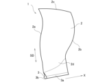
- FIG. 1 is a perspective view of a fan rotor blade, which is an example of a test piece held by a jig according to an embodiment of the present disclosure.
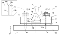
- FIG. 2 is a front view of a jig according to an embodiment of the present disclosure;
- FIG. 3 is a top view of a jig according to an embodiment of the present disclosure;
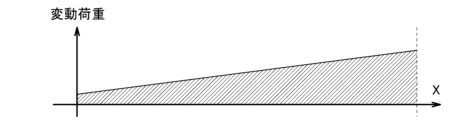
- FIG. 4A is a graph showing a varying load at positions along the X direction in a region where a reinforcement according to an embodiment of the present disclosure is placed;
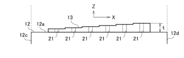
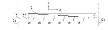
- FIG. 4B is a side view of a reinforcing portion having a thickness set based on the graph of FIG. 4A.
- FIG. 5A is a graph showing varying loads at positions along the X direction in a region where reinforcements according to embodiments of the present disclosure are placed.
- FIG. 5B is a side view of a reinforcement having a thickness set based on the graph of FIG. 5A.
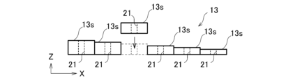
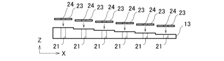
- FIG. 6 is a side view of a modification of the reinforcing portion according to the embodiment of the present disclosure; 7 is a side view of a washer in accordance with an embodiment of the present disclosure; FIG.
- FIG. 1 is a perspective view of a fan rotor blade 1, which is an example of a test piece held by a jig 10.
- FIG. 2 is a front view of the jig 10 according to this embodiment.
- FIG. 3 is a top view of the jig 10.
- illustration of the base 11 and the blade root portion 3 shown in FIG. 2 is omitted in FIG.
- symbol is attached
- the X direction, Y direction and Z direction that are orthogonal to each other are defined.
- the X direction and Y direction are parallel to a plane (virtual plane) including the vibration direction of the vibration table (not shown).
- the X direction is the extending direction of the slot 16 (see FIG. 3), and is also the direction parallel to the slot 16 from the side surface 12c to the side surface 12d of the top plate 12.
- the Z direction is orthogonal to the X and Y directions. Thicknesses at various locations described later refer to thicknesses (lengths) along the Z direction.
- the jig 10 is a vibration test jig.
- the jig 10 is mounted on a vibration table (not shown) of the vibration tester and holds the end of the specimen.
- the end of the specimen has a cross-sectional shape that is pressed against the base 11 by the top plate 12 .
- the specimen is a so-called elongated object, and has an end portion extending in the X direction and a main body extending from the end portion in a predetermined direction intersecting the XY plane (eg, Z direction).
- a fan blade 1 used in an aircraft engine such as a turbofan engine (not shown) will be described below as an example of a test piece.
- a fan rotor blade 1 as a test piece includes a blade body 2 as a main body of the test piece and a blade root portion 3 as an end portion of the test piece.
- the wing body 2 and the blade root portion 3 are formed as an integral body.
- the wing body 2 has a leading edge 2a, a trailing edge 2b, a tip 2c and a hub 2d.
- the blade body 2 extends in the span direction SD from the blade root portion 3 to the tip 2c via the hub 2d.
- the blade root portion 3 is connected to the hub 2d of the blade body 2 and extends in one direction so as to fit into a groove (dovetail groove) of a rotor (not shown) to which the fan rotor blade 1 is attached.
- the extending direction of the blade root portion 3 may coincide with the X direction.
- the blade root portion 3 is mounted on the mounting surface 11a of the base 11 (see FIG. 2).
- the blade root portion 3 has a pair of side surfaces 3a, 3a (see FIG. 2) and a bottom surface 3b (see FIG. 2).
- the blade root portion 3 has a cross-sectional shape complementary to the cross-sectional shape of the above-described groove portion (not shown). That is, the blade root portion 3 includes a width that widens in the Y direction as the distance from the blade body 2 increases.
- a pair of side surfaces 3a, 3a are slopes that define this width.
- a bottom surface 3b is located between and connects the sides 3a, 3a.
- the jig 10 includes a base 11, a top plate 12, a reinforcing portion 13, and a plurality of pressing members .
- the pressing member 14 is composed of a bolt 15 integrally formed with a threaded portion 14a and a head portion 14b.
- the pressing member 14 may be configured by a set of a threaded portion 14a formed as a stud bolt and a nut 14c screwed onto the threaded portion 14a (see FIG. 2).
- the reinforcing portion 13 is pressed toward the base 11 by tightening the bolt 15 in the former case and the nut 14c in the latter case.
- the bolt 15 will be described below as an example of the pressing member 14 .
- the base 11 is a flat plate having a predetermined thickness, and is made of a highly rigid metal such as stainless steel.
- the thickness of the base 11 is set to a value that provides sufficient rigidity against the axial force of the bolt 15 during fastening and the stress during vibration.
- the base 11 is installed on a vibration table (not shown) of a vibration test apparatus, and is fixed with a fastening member such as a bolt while its orientation is adjusted so as to obtain a desired vibration direction.
- the base 11 includes a mounting surface 11a on which the blade root portion 3 is mounted.
- the mounting surface 11 a faces the top plate 12 and is formed as, for example, the top surface of the mounting table 11 b that protrudes from the base 11 toward the top plate 12 .
- the height of the mounting table 11b according to this embodiment is set to a value that can maintain the gap between the base 11 and the top plate 12 when the top plate 12 presses the blade root portion 3 against the mounting surface 11a.
- the top plate 12 is a rectangular flat plate having a predetermined thickness, and is placed on the base 11 with a gap therebetween. Similar to the base 11, the top plate 12 is also made of a highly rigid metal such as stainless steel. The thickness of the top plate 12 is set to a value that provides sufficient rigidity against the axial force of the bolt 15 during fastening and the stress during vibration. In addition, the shape of the top plate 12 is not limited to a rectangle, and other shapes such as a circle may be used.
- the top plate 12 has a slot (retaining groove) 16 in which at least part of the blade root portion 3 is accommodated.
- the slot 16 opens in the upper surface 12a of the top plate 12 and extends in the X direction.
- the slot 16 is also open to at least one of the side surfaces 12c and 12d (see FIG. 3) of the top plate 12 as an insertion port 17 for the blade root portion 3.
- the slot 16 extends from one of the side surfaces 12c, 12d of the top plate 12 to the other.
- the side surfaces 12c and 12d of the top plate 12 are provided with insertion openings 17, respectively.
- the slot 16 also opens to the lower surface 12b of the top plate 12 as an insertion port 18 for the mounting table 11b.
- the insertion opening 18 penetrates from the bottom surface 16b, which is a part of the inner surface 16a of the slot 16, to the bottom surface 12b of the top plate 12. As shown in FIG.
- the slot 16 has an inner surface 16a that presses the blade root portion 3 positioned in the slot 16 toward the mounting surface 11a. That is, the cross section of the slot 16 orthogonal to the X direction includes contours corresponding to the side surfaces 3a, 3a of the blade root 3 located in the slot 16. As shown in FIG. As a result, a portion of the inner surface 16a comes into contact with the pair of side surfaces 3a, 3a of the blade root portion 3. As shown in FIG.
- the depth of the slot 16 along the Z direction is greater than the length along the Z direction of the portion of the blade root 3 accommodated within the slot 16 .
- the width of the bottom surface 16b of the slot 16 along the Y direction is wider than the width of the blade root portion 3 along the Y direction.
- a portion that includes the bottom surface 16b of the slot 16 and extends in the Y direction functions as a connecting portion 19 that connects the plate portion 12A on one side and the plate portion 12B on the other side with the slot 16 interposed therebetween.
- Threaded holes 20 (see FIG. 2) into which bolts 15 are screwed are formed on both sides along the slot 16 .
- the screw holes 20 are arranged in the X direction at predetermined intervals.
- the reinforcing part 13 is a flat plate-shaped member (bar-shaped member) that has a predetermined width in the Y direction and extends along the slot 16 (that is, in the X direction). A reinforcement 13 is placed on each side along the slot 16 .
- the reinforcing portion 13 is provided with a through hole 21 (see FIG. 4B) into which the bolt 15 is inserted.
- the through holes 21 are arranged in the X direction at predetermined intervals. This interval is equal to the interval between adjacent screw holes 20 in the X direction.
- the reinforcing portion 13 is made of a mutual metal material that is more rigid than the top plate 12 . Such material is for example chromium molybdenum steel (SCM).
- SCM chromium molybdenum steel
- a plurality of bolts 15 are arranged on the reinforcing portion 13 in the X direction and screwed into the base 11 via the reinforcing portion 13 and the top plate 12 .
- the top plate 12 moves toward the base 11. - ⁇ Therefore, when the bolt 15 is tightened while the blade root 3 is inserted into the slot 16 and placed on the mounting table 11b, the top plate 12 gradually descends, and the inner surface 16a of the slot 16 becomes the side surface 3a of the blade root 3. , 3a.
- the blade root portion 3 cannot be lowered because it is mounted on the mounting table 11b.
- the inner surface 16a of the slot 16 presses the side surfaces 3a, 3a of the blade root portion 3, and the blade root portion 3 is pressed against the mounting surface 11a of the mounting table 11b.
- the fan rotor blade 1 is held by the jig 10 .
- a strain sensor 22 is embedded in each bolt 15 .
- a strain sensor 22 measures the axial force generated in the bolt 15 . By checking the axial force measured by the strain sensor 22 when tightening the bolts 15 , a constant axial force can be set for each bolt 15 . Therefore, a positionally uniform load can be applied to the blade root portion 3 and the jig 10 .
- the load applied to the jig 10 fluctuates periodically according to the vibration of the fan rotor blades 1 .
- the maximum value of the fluctuating load changes for each position in the jig 10.
- plastic deformation is more likely to occur at a portion of the jig 10 where the fluctuating load is relatively large.
- the thickness t of the reinforcing portion 13 varies along the slot 16 according to the magnitude of the fluctuating load generated in the top plate 12 when the fan rotor blade 1 is vibrated. That is, the distribution of the fluctuating load generated on the top plate 12 when the fan rotor blade 1 is held by the jig 10 having a configuration other than the reinforcing portion 13 and is vibrated is calculated in advance, and the slots in the calculated distribution are calculated.
- the thickness t of the reinforcing portion 13 is set according to the magnitude of the fluctuating load at each position along the 16 (for example, each position of the bolt 15).
- the thickness of the reinforcing part 13 at the place where the load fluctuation is larger in the area where the reinforcing part 13 is placed also increases.
- the distribution of the magnitude of this fluctuating load may be calculated by an analysis method such as numerical analysis using the finite element method, or may be calculated from actual measurements by the strain sensor 22 .
- FIGS. 4A and 5B are diagrams for explaining setting of the thickness t of the reinforcing portion 13.
- FIG. FIGS. 4A and 5A are graphs showing examples of varying loads at positions along the X direction in the region where the reinforcing portion 13 is placed.
- FIG. 4B is a side view of the reinforcing portion 13 having a thickness set based on the graph of FIG. 4A.
- FIG. 5B is a side view of the reinforcing portion 13 having a thickness set based on the graph of FIG. 5A.
- the thickness of the reinforcement 13 at a certain position becomes t also increases as the position progresses in the X direction.
- the thickness of the top plate 12 may increase stepwise at each position of the through holes 21, or may increase continuously.
- the portion of the bolt 15 with which the head portion 14b contacts is formed as a plane perpendicular to the direction in which the bolt 15 is inserted (the direction opposite to the Z direction in this embodiment).
- the thickness of the reinforcement 13 at a certain position becomes t also decreases as the position advances in the X direction.
- the thickness of the top plate 12 may be reduced stepwise at each position of the through holes 21 as shown in FIG. 5A, or may be reduced continuously.
- the distribution of the maximum value of the fluctuating load along the X direction changes depending on the shape, size, and material of the fan rotor blade 1 (that is, the test piece) held by the jig 10, or the direction of vibration of the fan rotor blade 1. .
- the thickness t of the reinforcing portion 13 at each position along the X direction is also set. Therefore, the change in the thickness t of the reinforcing portion 13 at each position along the X direction is not limited to monotonous increase or monotonous decrease.
- the reinforcing portion 13 by placing the reinforcing portion 13 on the top plate 12, it is possible to increase the rigidity of the portion where the fluctuating load was large. Therefore, it is possible to reduce the excessive fluctuating load generated in the jig 10 when the specimen is vibrated. As a result, non-uniformity of the load distribution can be alleviated, local plastic deformation can be suppressed, and a uniform load (pressing force) can be maintained on the ends of the specimen. That is, shortening of the product life (usable period) of the jig 10 can be suppressed.
- FIG. 6 is a side view of a modified example of the reinforcing portion 13 according to this embodiment.
- the reinforcing portion 13 may be divided into reinforcing segments 13S for each bolt 15 (pressing member 14).
- reinforcing segments 13S of different thicknesses can be used to accommodate different fluctuating load distributions.
- the reinforcing portion 13 having a thickness suitable for changes in the vibration mode of the specimen can be configured simply by changing the arrangement of the reinforcing segments 13S.
- FIG. 7 is a side view of the plate member 23 according to this embodiment.
- the jig 10 according to this embodiment may include a plate member 23 sandwiched between the bolt 15 (pressing member 14 ) and the reinforcing portion 13 .
- the plate member 23 has an insertion hole 24 through which the threaded portion 14a is inserted, and is formed, for example, in an annular shape.
- the rigidity of the plate member 23 is lower than the rigidity of the reinforcing portion 13, for example, 1/2 or less of the rigidity of the reinforcing portion 13.
- a light metal such as aluminum or magnesium, hard rubber, hard resin, or the like is selected. Note that plate members made of different materials may be stacked and used.
- the base 11, the top plate 12, the reinforcing portion 13, and the pressing member 14 are made of metal with relatively high rigidity, such as stainless steel or SCM, in order to avoid excessive deformation due to load. Therefore, even if the bolt 15 is tightened only slightly, the axial force of the bolt 15 increases sharply. Also, due to the extreme increase in axial force, the axial force of the adjacent bolt 15 may decrease. That is, since the amount of increase in the axial force per one rotation of the bolt 15 is large, it is difficult to properly tighten the bolts, and it takes an enormous amount of time to obtain the above-described uniform axial force.
- the plate member 23 When the bolt 15 is tightened, the plate member 23 is sandwiched between the head portion 14b of the bolt 15 and the reinforcing portion 13. Since the plate member 23 is softer than the reinforcing portion 13, the amount of increase in the axial force per one rotation of the bolt 15 is reduced compared to the case where the plate member 23 is not provided. That is, it is possible to increase the rotation angle of the bolt 15 for obtaining the desired increase in axial force. Therefore, the adjustment of the axial force of the bolts 15 is facilitated, the work for obtaining a uniform axial force on the plurality of bolts 15 (pressing members 14) is eased, and the reinforcing portion 13 and the top plate 12 are properly applied with the axial force. can be attached to the base 11 with
Landscapes
- General Physics & Mathematics (AREA)
- Physics & Mathematics (AREA)
- Engineering & Computer Science (AREA)
- Chemical & Material Sciences (AREA)
- Combustion & Propulsion (AREA)
- Health & Medical Sciences (AREA)
- Aviation & Aerospace Engineering (AREA)
- Transportation (AREA)
- Manufacturing & Machinery (AREA)
- Life Sciences & Earth Sciences (AREA)
- Analytical Chemistry (AREA)
- Biochemistry (AREA)
- General Health & Medical Sciences (AREA)
- Immunology (AREA)
- Pathology (AREA)
- Structures Of Non-Positive Displacement Pumps (AREA)
- Testing Of Devices, Machine Parts, Or Other Structures Thereof (AREA)
Abstract
Description
Claims (3)
- 所定の方向に延伸する試験体の端部を保持する振動試験用治具であって、
前記試験体の前記端部が載置される載置面を含み、加振テーブルに設置される基台と、
前記試験体の前記端部を前記載置面に向けて押圧する内面をもつスロットを有し、前記基台上に間隔を置いて載置される天板と、
前記スロットに沿って前記天板に載置される補強部と、
前記スロットに沿って配置され、前記補強部を前記基台に向けて押圧する複数の押圧部材と
を備え、
前記補強部の厚さは、加振時の前記天板内に生じる変動荷重の大きさに応じて、前記スロットに沿って変化している
振動試験用治具。 - 前記補強部は、前記押圧部材毎の補強セグメントに分割されている
請求項1に記載の振動試験用治具。 - 各前記押圧部材と前記補強部の間に挟まれる板部材を備え、
前記板部材は前記補強部の剛性よりも低い剛性を有する
請求項1又は2に記載の振動試験用治具。
Priority Applications (3)
| Application Number | Priority Date | Filing Date | Title |
|---|---|---|---|
| EP22920389.8A EP4465006A4 (en) | 2022-01-14 | 2022-09-20 | VIBRATION TEST TEMPLATE |
| JP2023573837A JP7652299B2 (ja) | 2022-01-14 | 2022-09-20 | 振動試験用治具 |
| US18/751,431 US20240344923A1 (en) | 2022-01-14 | 2024-06-24 | Vibration test jig |
Applications Claiming Priority (2)
| Application Number | Priority Date | Filing Date | Title |
|---|---|---|---|
| JP2022-004180 | 2022-01-14 | ||
| JP2022004180 | 2022-01-14 |
Related Child Applications (1)
| Application Number | Title | Priority Date | Filing Date |
|---|---|---|---|
| US18/751,431 Continuation US20240344923A1 (en) | 2022-01-14 | 2024-06-24 | Vibration test jig |
Publications (1)
| Publication Number | Publication Date |
|---|---|
| WO2023135865A1 true WO2023135865A1 (ja) | 2023-07-20 |
Family
ID=87278771
Family Applications (1)
| Application Number | Title | Priority Date | Filing Date |
|---|---|---|---|
| PCT/JP2022/034877 Ceased WO2023135865A1 (ja) | 2022-01-14 | 2022-09-20 | 振動試験用治具 |
Country Status (4)
| Country | Link |
|---|---|
| US (1) | US20240344923A1 (ja) |
| EP (1) | EP4465006A4 (ja) |
| JP (1) | JP7652299B2 (ja) |
| WO (1) | WO2023135865A1 (ja) |
Cited By (1)
| Publication number | Priority date | Publication date | Assignee | Title |
|---|---|---|---|---|
| CN118730516A (zh) * | 2024-08-23 | 2024-10-01 | 江苏穹宇机械科技有限公司 | 电池污水处理用蒸发器的叶轮性能测试设备及其测试方法 |
Citations (5)
| Publication number | Priority date | Publication date | Assignee | Title |
|---|---|---|---|---|
| JP2003270081A (ja) * | 2002-03-19 | 2003-09-25 | Ishikawajima Harima Heavy Ind Co Ltd | タービン動翼の支持構造 |
| US20110179877A1 (en) * | 2010-01-27 | 2011-07-28 | Rolls-Royce Plc | Apparatus for generating vibrations in a component |
| JP2012137054A (ja) * | 2010-12-27 | 2012-07-19 | Mitsubishi Heavy Ind Ltd | 固定治具 |
| CN109029889A (zh) * | 2018-08-27 | 2018-12-18 | 烟台大学 | 一种航空发动机叶片的振动测试试验装置及其试验方法 |
| WO2020208925A1 (ja) | 2019-04-12 | 2020-10-15 | 株式会社Ihi | 動翼の振動試験用治具 |
Family Cites Families (1)
| Publication number | Priority date | Publication date | Assignee | Title |
|---|---|---|---|---|
| CN207408062U (zh) * | 2017-09-29 | 2018-05-25 | 苏州泰斯特测控科技有限公司 | 燕尾形榫头叶片疲劳测试装置 |
-
2022
- 2022-09-20 EP EP22920389.8A patent/EP4465006A4/en active Pending
- 2022-09-20 WO PCT/JP2022/034877 patent/WO2023135865A1/ja not_active Ceased
- 2022-09-20 JP JP2023573837A patent/JP7652299B2/ja active Active
-
2024
- 2024-06-24 US US18/751,431 patent/US20240344923A1/en active Pending
Patent Citations (5)
| Publication number | Priority date | Publication date | Assignee | Title |
|---|---|---|---|---|
| JP2003270081A (ja) * | 2002-03-19 | 2003-09-25 | Ishikawajima Harima Heavy Ind Co Ltd | タービン動翼の支持構造 |
| US20110179877A1 (en) * | 2010-01-27 | 2011-07-28 | Rolls-Royce Plc | Apparatus for generating vibrations in a component |
| JP2012137054A (ja) * | 2010-12-27 | 2012-07-19 | Mitsubishi Heavy Ind Ltd | 固定治具 |
| CN109029889A (zh) * | 2018-08-27 | 2018-12-18 | 烟台大学 | 一种航空发动机叶片的振动测试试验装置及其试验方法 |
| WO2020208925A1 (ja) | 2019-04-12 | 2020-10-15 | 株式会社Ihi | 動翼の振動試験用治具 |
Non-Patent Citations (1)
| Title |
|---|
| See also references of EP4465006A4 |
Cited By (1)
| Publication number | Priority date | Publication date | Assignee | Title |
|---|---|---|---|---|
| CN118730516A (zh) * | 2024-08-23 | 2024-10-01 | 江苏穹宇机械科技有限公司 | 电池污水处理用蒸发器的叶轮性能测试设备及其测试方法 |
Also Published As
| Publication number | Publication date |
|---|---|
| EP4465006A1 (en) | 2024-11-20 |
| JP7652299B2 (ja) | 2025-03-27 |
| JPWO2023135865A1 (ja) | 2023-07-20 |
| EP4465006A4 (en) | 2025-12-31 |
| US20240344923A1 (en) | 2024-10-17 |
Similar Documents
| Publication | Publication Date | Title |
|---|---|---|
| CN103076246B (zh) | 一种双轴高低循环复合疲劳试验装置 | |
| EP2351631B1 (en) | Apparatus for generating vibrations in a component | |
| US11815425B2 (en) | Jig for vibration test of rotor blade | |
| JP5812815B2 (ja) | フレッティング疲労試験治具、フレッティング疲労試験装置、及び、フレッティング疲労強度評価方法 | |
| CN104019968B (zh) | 一种测试螺旋桨叶疲劳性能的试验系统 | |
| CN108801822B (zh) | 一种预载荷高频振动疲劳试验装置 | |
| US20240344923A1 (en) | Vibration test jig | |
| JP5746215B2 (ja) | 横荷重装置 | |
| US6085593A (en) | Vibration damping element test apparatus | |
| JP5288689B2 (ja) | バニシ仕上げのプロセス制御のための方法及び装置 | |
| KR101385849B1 (ko) | 고무재료의 피로 및 피로균열진전 시험장치 | |
| CN108593234B (zh) | 高周疲劳试验装置及其应用 | |
| CN110887750A (zh) | 一种用于叶片弯曲高周疲劳试验的悬臂式试验装置及运行方法 | |
| JP7078917B2 (ja) | 静翼の振動試験用治具 | |
| CN116296186A (zh) | 一种多叶片同步随机等效加载疲劳试验装置 | |
| CN115728156A (zh) | 剪切疲劳试验方法及剪切疲劳寿命测试方法 | |
| CN210719932U (zh) | 摩擦磨损试样固定夹具 | |
| WO2023139842A1 (ja) | 振動試験用治具 | |
| Cristóvão et al. | Natural frequencies of roll-tensioned circular sawblades: Effects of roller loads, number of grooves, and groove positions | |
| CN110031344B (zh) | 一种材料剪切疲劳性能测试方法 | |
| RU2377531C1 (ru) | Способ нагружения плоского образца | |
| CN120927227B (zh) | 一种压电振子式试验装置及疲劳试验方法 | |
| CN114323514B (zh) | 多叶片振动疲劳试验方法及系统 | |
| KR20100002450A (ko) | 스트레인 게이지 부착용 공구 | |
| CN113884260B (zh) | 振级放大振动疲劳试验夹具 |
Legal Events
| Date | Code | Title | Description |
|---|---|---|---|
| 121 | Ep: the epo has been informed by wipo that ep was designated in this application |
Ref document number: 22920389 Country of ref document: EP Kind code of ref document: A1 |
|
| WWE | Wipo information: entry into national phase |
Ref document number: 2023573837 Country of ref document: JP |
|
| WWE | Wipo information: entry into national phase |
Ref document number: 2022920389 Country of ref document: EP |
|
| NENP | Non-entry into the national phase |
Ref country code: DE |
|
| ENP | Entry into the national phase |
Ref document number: 2022920389 Country of ref document: EP Effective date: 20240814 |