WO2023136024A1 - プレス成形品の外周形状評価方法、装置及びプログラム、並びにプレス成形品の製造方法 - Google Patents
プレス成形品の外周形状評価方法、装置及びプログラム、並びにプレス成形品の製造方法 Download PDFInfo
- Publication number
- WO2023136024A1 WO2023136024A1 PCT/JP2022/045840 JP2022045840W WO2023136024A1 WO 2023136024 A1 WO2023136024 A1 WO 2023136024A1 JP 2022045840 W JP2022045840 W JP 2022045840W WO 2023136024 A1 WO2023136024 A1 WO 2023136024A1
- Authority
- WO
- WIPO (PCT)
- Prior art keywords
- press
- formed product
- peripheral shape
- model
- outer peripheral
- Prior art date
- Legal status (The legal status is an assumption and is not a legal conclusion. Google has not performed a legal analysis and makes no representation as to the accuracy of the status listed.)
- Ceased
Links
Images


Classifications
-
- G—PHYSICS
- G06—COMPUTING OR CALCULATING; COUNTING
- G06F—ELECTRIC DIGITAL DATA PROCESSING
- G06F30/00—Computer-aided design [CAD]
- G06F30/10—Geometric CAD
-
- B—PERFORMING OPERATIONS; TRANSPORTING
- B21—MECHANICAL METAL-WORKING WITHOUT ESSENTIALLY REMOVING MATERIAL; PUNCHING METAL
- B21D—WORKING OR PROCESSING OF SHEET METAL OR METAL TUBES, RODS OR PROFILES WITHOUT ESSENTIALLY REMOVING MATERIAL; PUNCHING METAL
- B21D22/00—Shaping without cutting, by stamping, spinning, or deep-drawing
- B21D22/02—Stamping using rigid devices or tools
-
- G—PHYSICS
- G06—COMPUTING OR CALCULATING; COUNTING
- G06F—ELECTRIC DIGITAL DATA PROCESSING
- G06F30/00—Computer-aided design [CAD]
- G06F30/10—Geometric CAD
- G06F30/17—Mechanical parametric or variational design
-
- G—PHYSICS
- G06—COMPUTING OR CALCULATING; COUNTING
- G06F—ELECTRIC DIGITAL DATA PROCESSING
- G06F30/00—Computer-aided design [CAD]
- G06F30/20—Design optimisation, verification or simulation
- G06F30/23—Design optimisation, verification or simulation using finite element methods [FEM] or finite difference methods [FDM]
-
- B—PERFORMING OPERATIONS; TRANSPORTING
- B21—MECHANICAL METAL-WORKING WITHOUT ESSENTIALLY REMOVING MATERIAL; PUNCHING METAL
- B21D—WORKING OR PROCESSING OF SHEET METAL OR METAL TUBES, RODS OR PROFILES WITHOUT ESSENTIALLY REMOVING MATERIAL; PUNCHING METAL
- B21D22/00—Shaping without cutting, by stamping, spinning, or deep-drawing
- B21D22/20—Deep-drawing
-
- G—PHYSICS
- G06—COMPUTING OR CALCULATING; COUNTING
- G06F—ELECTRIC DIGITAL DATA PROCESSING
- G06F2113/00—Details relating to the application field
- G06F2113/22—Moulding
-
- G—PHYSICS
- G06—COMPUTING OR CALCULATING; COUNTING
- G06F—ELECTRIC DIGITAL DATA PROCESSING
- G06F2113/00—Details relating to the application field
- G06F2113/24—Sheet material
Definitions
- the present invention relates to the peripheral shape of an actual press formed part that is actually press formed, and the peripheral shape of the press formed analysis model obtained by press forming analysis. and a press-formed article outer peripheral shape evaluation method, apparatus, and program for comparing and evaluating each of them. Furthermore, the present invention is a press molding that manufactures an actual press-molded product with improved dimensional accuracy by adjusting the press molding conditions so that the dimensional accuracy of the outer peripheral shape is improved and actually performing press molding. It relates to the manufacturing method of goods.
- the outer shape of the press-formed product depends on the setting position of the blank in the die used for press-forming, the self-weight deflection when the blank is set in the die, and the die when the blank is sandwiched between the dies. It is greatly affected by three factors: contact with the surface and sliding conditions. Therefore, whether or not the outer peripheral shapes of the actual press-formed product and the press-formed product obtained by mechanical analysis match is a criterion for judging whether these three elements are appropriate. In particular, in deep drawing (drawing), in which the edges of the blank are first sandwiched between dies and then the central part of the blank is formed, the peripheral shape of the press-formed product depends on whether it can be formed. is an important factor that influences
- Non-Patent Document 1 the characteristic characteristics of the blank end and the press-formed product A method of measuring the distance between the parts of the shape and comparing it with the analysis result of the mechanical analysis, or as disclosed in Non-Patent Document 2, the original (before press forming) blank shape and overlapping Accuracy of the peripheral shape of the press-formed product obtained by mechanical analysis is evaluated by evaluating the amount of change in the external shape (inflow). This is the same when evaluating the outer peripheral shape of a plurality of press-formed products obtained by dynamic analysis with changed analysis conditions. This is because even press-formed products molded with the same mold do not necessarily have the same outer peripheral shape after springback due to, for example, differences in lubricating oil and material strength.
- Non-Patent Document 1 in the method of measuring the distance between the edge of the blank and the characteristic shape in the press-molded product and comparing it with the mechanical analysis result, for example, the ridge line of the mold
- the ridge line of the mold When measuring the distance between the (ridge line section) edge and the blank edge, it is difficult to precisely determine the position of the edge of the ridge line because the ridge line is a curved surface. For this reason, there is room for differences depending on the measurer, for example.
- Non-Patent Document 2 in the method of evaluating the amount of change (inflow amount) of the outer shape by overlapping it with the original blank shape, what criteria are used for the original blank shape and the molded product? Since the results differ greatly depending on whether or not they are superimposed, there is room for differences depending on the measurer, and it was difficult to define the measurement criteria clearly. Therefore, it has been a challenge to compare the outer peripheral shapes with high reproducibility and accuracy regardless of the measurer.
- the contact pressure distribution from the mold in the press-molded product at the bottom dead center of molding is considered to be important information regarding the outer peripheral shape of the press-molded product.
- the contact pressure distribution acting on the press-formed product by mechanical analysis no method has been established for determining the contact pressure distribution from the die in the actual press-formed product. Therefore, even if the outer peripheral shapes of the actual press-formed product and the press-formed product obtained by mechanical analysis could be compared, the cause of the difference in the outer peripheral shape could not be properly evaluated.
- the present invention has been made to solve the above problems, and its purpose is to analyze the outer peripheral shape of the actual press-formed product and the process of press-molding the actual press-formed product. It is possible to compare the outer shape of the press-formed product analysis model obtained by (elastoplastic mechanical analysis) with high reproducibility and accuracy, and to evaluate the outer shape of each press-formed product appropriately. It is to provide a peripheral shape evaluation method, an apparatus and a program. Furthermore, another object of the present invention is to improve the prediction accuracy based on the evaluation of the outer peripheral shape of the press-formed product analysis model, adjust the press forming conditions so that the dimensional accuracy of the outer peripheral shape is improved, and improve the dimensional accuracy. To provide a method of manufacturing a press-formed product for manufacturing an actual press-formed product with improved
- the method for evaluating the outer peripheral shape of a press-formed product according to the present invention includes the outer peripheral shape of an actual press-formed product obtained by press-molding a blank using a mold, and the elasto-plastic dynamics of the process of press-molding the actual press-formed product.
- the outer shape of the press-formed product analysis model obtained by analysis is compared to evaluate each, and the surface shape after the actual press-formed product is die released and springback is measured
- a process of creating a work shape model of a press-formed product from the three-dimensional surface profile measurement data obtained by Perform a dynamic analysis obtain a press-formed product workpiece bottom dead center shape model at the molding bottom dead center, and acquire the outer peripheral shape of the obtained press-formed product work bottom dead center shape model as the outer peripheral shape of the actual press-formed product
- An actual press-formed product outer shape acquisition step and an elasto-plastic dynamic analysis of the process of press-forming the blank model of the blank using the mold model are performed over a single step or multiple steps, forming bottom dead center
- the mechanical analysis in the actual press-formed product outer shape acquisition step is elastic finite element analysis or elastoplastic finite element analysis, and the press-formed product analysis model outer shape acquisition step
- the elastic-plastic dynamic analysis in is preferably elastic-plastic finite element analysis.
- the mold model in the step of acquiring the outer peripheral shape of the actual press-formed product is the actual press-formed product. It is preferable that the mold models of the molds for molding the respective parts of are combined to form a single mold model.
- the contact pressure distribution with the die model acting on the press-formed work piece bottom dead center shape model obtained in the actual press-formed product outer peripheral shape acquisition step The contact pressure with the die model acting on the press-formed product analysis model at the forming bottom dead center determined in the step of calculating the actual press-formed product contact pressure distribution calculated as a distribution, and the step of acquiring the outer peripheral shape of the press-formed product analysis model
- the contact pressure distribution with the die model acting on the press-formed work piece bottom dead center shape model obtained in the actual press-formed product outer peripheral shape acquisition step The contact pressure with the die model acting on the press-formed product analysis model at the forming bottom dead center determined in the step of calculating the actual press-formed product contact pressure distribution calculated as a distribution, and the step of acquiring the outer peripheral shape of the press-formed product analysis model
- the apparatus for evaluating the outer peripheral shape of a press-formed product includes the outer peripheral shape of an actual press-formed product obtained by press-molding a blank using a mold, and the elasto-plastic dynamics of the process of press-molding the actual press-formed product.
- the outer shape of the press-formed product analysis model obtained by analysis is compared and each is evaluated.
- a work shape model of the press-formed product is created from the original surface shape measurement data, and a mechanical analysis is performed in the process of sandwiching the work shape model of the press-formed product by the mold model of the mold to the bottom dead point of the forming.
- an actual press-formed product outer peripheral shape acquisition unit that obtains a press-formed product work bottom dead center shape model in and acquires the outer peripheral shape of the obtained press-formed product work bottom dead center shape model as the outer peripheral shape of the actual press-formed product;
- a press-formed product analysis model at the bottom dead center of the molding is obtained, and the obtained
- a press-formed product analysis model peripheral shape acquisition unit for acquiring the peripheral shape of the press-formed product analysis model, the peripheral shape of the actual press-formed product acquired by the actual press-formed product peripheral shape acquisition unit, and the press-formed product analysis a peripheral shape comparison/evaluation unit that compares the peripheral shape of the press-formed product analysis model acquired by the model peripheral shape acquisition unit and evaluates each peripheral shape.
- the distribution of contact pressure with the mold model acting on the bottom dead center shape model of the press-formed product obtained in the actual press-formed product outer peripheral shape acquisition unit The contact pressure between the actual press-formed product contact pressure distribution calculation unit calculated as a distribution and the mold model acting on the press-formed product analysis model at the forming bottom dead center obtained by the press-formed product analysis model outer peripheral shape acquisition unit
- a press-formed product analysis model contact pressure distribution calculating unit that calculates the distribution, a contact pressure distribution acting on the actual press-formed product calculated by the actual press-formed product contact pressure distribution calculator, and the press-formed product analysis model contact pressure It is preferable to further include a contact pressure distribution comparison/evaluation unit that compares the contact pressure distribution acting on the press-formed product analysis model calculated by the distribution calculation unit and evaluates each of them.
- the peripheral shape evaluation program for a press-formed product includes the peripheral shape of an actual press-formed product obtained by press-molding a blank using a mold, and the elasto-plastic dynamics of the process of press-molding the actual press-formed product.
- the outer peripheral shape of the press-formed product analysis model obtained by analysis is compared and each is evaluated.
- a work shape model of the press-formed product is created from the acquired three-dimensional surface shape measurement data, and a mechanical analysis is performed in the process of sandwiching the work shape model of the press-formed product by the mold model of the mold to the bottom dead point of the molding.
- a press-formed product analysis model at the bottom dead center of forming is obtained by performing an elasto-plastic dynamics analysis of the process of press-forming the blank model of the blank using the mold model over a single step or multiple steps.
- a press-formed product analysis model outer peripheral shape acquisition unit for acquiring the outer peripheral shape of the obtained press-formed product analysis model, the outer peripheral shape of the actual press-formed product acquired by the actual press-formed product outer peripheral shape acquisition unit, and the press It functions as an outer peripheral shape comparison/evaluation unit that compares the outer peripheral shape of the press-formed product analysis model acquired by the molded product analysis model outer peripheral shape acquisition unit and evaluates each outer peripheral shape.
- the computer is further configured to apply the contact pressure distribution with the mold model acting on the press-formed product workpiece bottom dead center shape model obtained in the actual press-formed product outer peripheral shape acquisition unit to the actual press-formed product.
- the actual press-formed product contact pressure distribution calculation unit that calculates the contact pressure distribution from the mold, and the press-formed product analysis model at the bottom dead center obtained by the press-formed product analysis model outer peripheral shape acquisition unit.
- a press-formed product analysis model contact pressure distribution calculator that calculates a contact pressure distribution with a mold model; a contact pressure distribution acting on the actual press-formed product calculated by the actual press-formed product contact pressure distribution calculator; It is preferable to function as a contact pressure distribution comparison/evaluation unit that compares the contact pressure distribution acting on the press-formed product analysis model calculated by the molded product analysis model contact pressure distribution calculation unit and evaluates each of them.
- the method for producing a press-formed product according to the present invention is for producing an actual press-formed product by adjusting the press-forming conditions so that the dimensional accuracy of the outer peripheral shape is improved.
- the outer peripheral shape at the bottom dead center of the press-formed product analysis model obtained by elastic-plastic dynamics analysis of the process of press-forming the actual press-formed product, and the blank using the actual mold
- an analysis condition adjustment step of adjusting the analysis conditions of the press-formed product analysis model in the elastic-plastic dynamic analysis of the process of press-forming the actual press-formed product Based on the prediction accuracy of the outer peripheral shape of the product analysis model, an analysis condition adjustment step of adjusting the analysis conditions of the press-formed product analysis model in the elastic-plastic dynamic analysis of the process of press-forming the actual press-formed product;
- a press-formed work shape model created based on the three-dimensional surface shape of an actual press-formed product that was actually press-formed, and an elastic-plastic dynamics analysis of the process of press-forming the actual press-formed product.
- the analysis model of the press-formed product is aligned with the bottom dead center of the same mold model. Therefore, the outer peripheral shape of the actual press-formed product at the forming bottom dead center before springback and the outer peripheral shape of the press-formed product analysis model can be accurately compared with high reproducibility, and each can be evaluated appropriately.
- the difference between the outer peripheral shape of the actual press-formed product at the bottom dead point of the forming and the outer peripheral shape of the press-formed product analysis model can be It can be evaluated in association with the difference in contact pressure distribution at the dead point.
- the analysis conditions in the mechanical analysis can be set correctly while comparing with the actual press-molded product, so that molding defects such as poor dimensional accuracy can be prevented.
- by detecting an abnormality in actual press molding and correcting it it is possible to prevent molding defects.
- the analysis conditions for the elastic-plastic dynamics analysis of the press forming process are set so as to increase the prediction accuracy. adjust.
- the forming conditions are adjusted so that the dimensional accuracy of the outer peripheral shape of the press-formed product analysis model is improved. Then, by press-molding using an actual mold under the adjusted press-molding conditions, it is possible to manufacture an actual press-molded product with improved dimensional accuracy of the outer peripheral shape. This can prevent troubles when assembling parts with other parts.
- the actual press molding conditions can be changed according to signs of changes in the outer peripheral shape during mass production of actual press molded products, such as wear and deformation of the mold. Therefore, it is possible to suppress the occurrence of a large number of dimensional defects in the outer peripheral shape of the actual press-formed product.
- FIG. 1 is a flowchart for explaining the processing flow of the method for evaluating the peripheral shape of a press-formed product according to Embodiment 1 of the present invention.
- FIG. 2 is a diagram for explaining the process of acquiring the outer peripheral shape of an actual press-formed product in the method for evaluating the outer peripheral shape of a press-formed product according to Embodiment 1 of the present invention ((a) Pressing of an actual press-formed product) Molding process, (b) measurement of three-dimensional surface shape of actual press-formed product, (c) conversion of three-dimensional surface shape data to press-formed work shape model (remeshing and offset), (d) Dynamic analysis of the process of sandwiching the press-formed work shape model between the die models, (e) Acquisition of the outer peripheral shape of the press-formed work bottom dead center shape model at the bottom dead center of the forming).
- FIG. 3 shows (a) the outer peripheral shape of the actual press-formed product obtained using the press-formed product work bottom dead center shape model, which is obtained by the method for evaluating the outer peripheral shape of the press-formed product according to Embodiment 1 of the present invention. (b) Peripheral shape of press-formed product analysis model acquired by press-forming analysis, (c) Comparison between the outer peripheral shape of an actual press-formed product and the outer peripheral shape of the press-formed product analysis model.
- FIG. 4 is a flowchart for explaining the flow of processing of another aspect of the method for evaluating the peripheral shape of a press-formed product according to Embodiment 1 of the present invention.
- FIG. 5 shows an example of the contact pressure distribution of the press-formed work bottom dead center shape model and the press-formed product analysis model obtained in another aspect of the method for evaluating the outer peripheral shape of the press-formed product according to Embodiment 1 of the present invention.
- (a) contact pressure distribution of press-formed product workpiece bottom dead center shape model (b) contact pressure distribution of press-formed product analysis model).
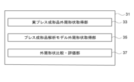
- FIG. 6 is a block diagram of an apparatus for evaluating the peripheral shape of a press-formed product according to Embodiment 1 of the present invention, and a diagram for explaining the function of a program for evaluating the peripheral shape of a press-formed product according to Embodiment 1 of the present invention. is.
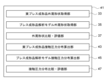
- FIG. 7 is a block diagram of another aspect of the apparatus for evaluating the peripheral shape of a press-formed product according to Embodiment 1 of the present invention, and another embodiment of the peripheral shape evaluation program for a press-formed product according to Embodiment 1 of the present invention.
- FIG. 4 is a diagram illustrating the functioning of aspects;
- Fig. 8 explains the problem when comparing the outer peripheral shape of the press-formed product analysis model obtained by press forming analysis and springback analysis with the outer peripheral shape of the actual press-formed product after press forming and springback.
- (b) actual press-formed product (c) three-dimensional surface shape measurement data of actual press-formed product).
- FIG. 1 is a block diagram of another aspect of the apparatus for evaluating the peripheral shape of a press-formed product according to Embodiment 1 of the present invention, and another embodiment of the peripheral shape evaluation program for a press-formed product according to Embodiment 1 of the present invention
- FIG. 10 shows, in the method for manufacturing a press-formed product according to Embodiment 2 of the present invention, (a) the outer periphery of the press-formed product workpiece bottom dead center shape model acquired as the outer peripheral shape at the forming bottom dead center of the actual press-formed product. Shape, (b) Peripheral shape at the bottom dead center of the press-formed product analysis model obtained by elasto-plastic finite element analysis by adjusting the analysis conditions, (c) Peripheral shape at the bottom dead center of the actual press-formed product and press FIG. 10 is a diagram showing a comparison of the outer peripheral shape at the molding bottom dead center of the molded product analysis model;
- FIG. 1 A method, apparatus, and program for evaluating the peripheral shape of a press-formed product according to Embodiment 1 of the present invention will be described below with reference to FIGS. 1 to 7.
- FIG. 1 an actual press-formed product 11 having a hat-shaped cross section simulating an A-pillar upper (front pillar upper) of an automobile, shown in FIG. .
- the actual press-formed product 11 is formed by press-forming a cold rolled steel sheet of 980 MPa class (MPa-class) and 1.4 mm in thickness.
- MPa-class MPa class
- the method for evaluating the outer peripheral shape of a press-formed product according to Embodiment 1 of the present invention is, as shown in FIG. , and, as an example, as shown in FIG. and are compared and evaluated.
- the method for evaluating the peripheral shape of a press-formed product includes an actual press-formed product peripheral shape acquisition step S1, a press-formed product analysis model peripheral shape acquisition step S3, and a peripheral shape comparison/evaluation step S5. include.
- S1 actual press-formed product peripheral shape acquisition step S1
- a press-formed product analysis model peripheral shape acquisition step S3 a peripheral shape comparison/evaluation step S5.
- step S1 for acquiring the outer peripheral shape of the actual press-formed product the press-formed product work shape model 15 is obtained from the three-dimensional surface shape measurement data 13 obtained by measuring the surface shape after releasing the actual press-formed product 11 and springing back. Then, a press-formed work shape model 15 is mechanically analyzed in the process of sandwiching the press-formed work shape model 15 by the mold model 1 of the mold to the bottom dead point of the forming, and a press-formed work shape model 17 at the bottom dead center of the forming is obtained. is a step of acquiring the outer peripheral shape of the press-formed product workpiece bottom dead center shape model 17 as the outer peripheral shape of the actual press-formed product 11 .
- the actual press-formed product outer shape acquisition step S1 first, as shown in FIGS. ).
- a press-formed work shape model 15 is created by remeshing to elements of an element size (for example, triangular elements) and then offsetting to a position corresponding to the center of the plate thickness (S1b).
- the three-dimensional surface profilometry data 13 may be subjected to an operation to remove noise near edges (contours).
- the plate thickness of the work shape model 15 of the press-formed product is treated as a constant initial plate thickness of 1.4 mm, but the plate thickness measured for each element or for each region may be given.
- the obtained 3D surface shape measurement data is offset to the back side by the plate thickness to acquire 3D surface shape measurement data, or to acquire the 3D surface shape measurement data, or By measuring the three-dimensional surface shape measurement data for each of them, the three-dimensional surface shape measurement data for both the front and back surfaces is obtained, and the three-dimensional space sandwiched by these three-dimensional surface shape measurement data for the front and back surfaces is defined as a solid element. ) to create a press-formed work shape model.
- the press-molded product workpiece shape model 15 is placed at a position where it can be sandwiched between the mold models 1 (S1c). At this time, the positioning of the press-formed work shape model 15 may be roughly manually adjusted so that the press-formed work shape model 15 does not deviate greatly in the process of being clamped by the mold model 1 to the bottom dead center of molding.
- the press-formed product workpiece shape model 15 and the mold model 1 are sandwiched between the mold model 1 with the characteristic shapes such as the ridge line shape, outer peripheral shape, positioning hole/pin, etc. as marks, the press-formed product Parallel movement and/or rotational movement are performed so that the characteristic shape portion of the workpiece shape model 15 does not shift.
- the press-molded product work shape model 15 is automatically aligned with the lower die model 3 of the mold model 1 as a reference, such as best fit, and then the upper die model 5 may be moved in parallel along the press forming direction until it does not come into contact with the lower mold model 3 .
- elastic finite element analysis is performed as the dynamic analysis in the step S1 for obtaining the outer peripheral shape of the actual press-formed product, but this is not limiting, and elastic-plastic finite element analysis may be performed.
- the press-formed work bottom dead center shape model is obtained with the mold model 1 as a reference. 17 alignments are possible.
- the first embodiment is directed to the case of crash forming the actual press-molded product 11 using a mold having a lower mold and an upper mold, but in the case of draw molding,
- the mold is provided with a cushion (blank holder) that holds the blank in cooperation with the upper mold.
- the mold model is provided with a cushion model (not shown), and the cushion model is placed at the bottom dead center of the molding from the beginning, and the press-formed work shape model is sandwiched between the lower die model and the upper die model. It is sufficient to analyze the process.
- press-formed product analysis model outer shape acquisition step S3 by performing an elastic-plastic dynamics analysis of the process of press-forming the blank model using the mold model 1, as shown in FIG.
- the press-formed product analysis model 21 at the bottom dead center is obtained, and the outer peripheral shape of the press-formed product analysis model 21 obtained is acquired.
- the press-formed product analysis model outer shape acquisition step S3 performs elastic-plastic finite element analysis as elastic-plastic dynamic analysis.
- a blank model (not shown) used for press-forming analysis of the press-formed product analysis model 21 and a mold model 1 ( FIG. 2(d)) and are obtained in advance.
- the outer peripheral shape comparison/evaluation step S5 the outer peripheral shape of the actual press-formed product 11 acquired in the actual press-formed product peripheral shape acquisition step S1 and the press-formed product analysis model 21 acquired in the press-formed product analysis model peripheral shape acquisition step S3. is a step of comparing each outer peripheral shape with the outer peripheral shape of .
- FIG. 3C shows the outer peripheral shape at the bottom dead center of the press-formed product analysis model 21 acquired by the method for evaluating the outer peripheral shape of the press-formed product according to the first embodiment, and the bottom dead center of the actual press-formed product 11.
- the result of comparison with the outer peripheral shape of the press-formed workpiece bottom dead center shape model 17 obtained as the outer peripheral shape at the point is shown. It was found that although the outer peripheral shape of the press-formed product analysis model 21 and the outer peripheral shape of the actual press-formed product 11 were substantially the same, there was a deviation between the two.
- the actual press-formed product 11 targeted in the present embodiment 1 is provided with locating pins (see FIG. 2) at two locations on the mold to prevent the blank from shifting during the press-forming process. Therefore, the difference between the two was small.
- the press-formed product work bottom dead center shape model 17 obtained as the outer peripheral shape at the forming bottom dead center of the actual press-formed product 11
- the press-formed product analysis model 21 at the bottom dead center of the forming process and the press-formed product analysis model 21 are both positioned with the same mold model 1 . Therefore, by comparing the outer peripheral shape of the press-formed product analysis model 21 with the outer peripheral shape of the actual press-formed product 11 as a reference, reproducibility is high and accurate.
- the step of acquiring the outer peripheral shape of the press-formed product according to the above-described first embodiment of the method for evaluating the outer peripheral shape of the press-formed product In addition to S1, the press-formed product analysis model outer shape acquisition step S3, and the outer shape comparison/evaluation step S5, as shown in FIG. It can be configured to further include an analysis model contact pressure distribution calculation step S9 and a contact pressure distribution comparison/evaluation step S11.
- the actual press-formed product contact pressure distribution calculation step S7 calculates the contact pressure with the mold model 1 acting on the press-formed product workpiece bottom dead center shape model 17 at the forming bottom dead center determined in the actual press-formed product outer peripheral shape acquisition step S1. This is a step of calculating the distribution as a contact pressure distribution from the mold acting on the actual press-formed product 11 .
- the press-formed product analysis model contact pressure distribution calculation step S9 calculates the contact pressure distribution with the mold model 1 acting on the press-formed product analysis model 21 at the forming bottom dead center obtained in the press-formed product analysis model outer peripheral shape acquisition step S3. This is the step of calculating.
- the contact pressure distribution comparison/evaluation step S11 includes the contact pressure distribution acting on the actual press-formed product 11 calculated in the actual press-formed product contact pressure distribution calculation step S7 and the contact pressure distribution calculated in the press-formed product analysis model contact pressure distribution calculation step S9. It is a step of comparing the contact pressure distribution acting on the press-formed product analysis model 21 and evaluating each of them.
- FIG. 5 shows a press-formed product obtained as a contact pressure distribution at the forming bottom dead center acting on the actual press-formed product 11, which is obtained by another aspect of the method for evaluating the outer peripheral shape of the press-formed product according to Embodiment 1.
- 2 shows contour diagrams of the contact pressure distribution of the product workpiece bottom dead center shape model 17 and the contact pressure distribution at the forming bottom dead center of the press-formed product analysis model 21.
- the press-formed product workpiece bottom dead center shape model 17 is obtained by changing the punch bottom portion 17a and the flange portion 17b of the press-formed product analysis model 21 to the punch bottom portion 21a and flange portion 17b. It can be seen that the contact pressure is higher than that of 21b. Therefore, the difference in the outer peripheral shape between the press-formed work piece bottom dead center shape model 17 and the press-formed product analysis model 21 shown in FIG. It is considered to be a thing.
- the difference between the outer peripheral shape of the actual press-formed product and the outer peripheral shape of the press-formed product analysis model is It can be evaluated in relation to the difference in contact pressure distribution at points.
- the analysis conditions in the mechanical analysis can be set correctly while comparing with the actual press-molded product, so that molding defects such as poor dimensional accuracy can be prevented.
- by detecting an abnormality in actual press molding and correcting it it is possible to prevent molding defects.
- the apparatus 31 for evaluating the outer peripheral shape of a press-formed product according to the first embodiment of the present invention is an actual press-formed product in which a blank is actually press-formed using a mold.
- the outer peripheral shape at the bottom dead center of molding is compared and each is evaluated.
- the press-formed product peripheral shape evaluation device 31 includes an actual press-formed product peripheral shape acquisition unit 33, a press-formed product analysis model peripheral shape acquisition unit 35, a peripheral shape comparison/evaluation unit 37, Prepare.
- the actual press-formed product outer peripheral shape acquisition unit 33 measures the surface shape of the actual press-formed product 11 after it has been released from the mold and spring-backed.
- a press-formed work shape model 15 is created, and a mechanical analysis is performed on the process in which the press-formed work shape model 15 is sandwiched by the mold model 1 of the mold until the bottom dead point of the forming process.
- a point shape model 17 is obtained, and the outer peripheral shape of the press-formed product workpiece bottom dead center shape model 17 is acquired as the outer peripheral shape of the actual press-formed product 11 .
- the actual press-formed product outer peripheral shape acquisition unit 33 executes the actual press-formed product outer peripheral shape acquisition step S1 of the method for evaluating the outer peripheral shape of the press-formed product according to the first embodiment described above.
- the press-formed product analysis model outer peripheral shape acquisition unit 35 performs elastic-plastic dynamics analysis of the process of press-forming the blank model using the mold model 1, so that as shown in FIG.
- the press-formed product analysis model 21 at the bottom dead center is obtained, and the outer peripheral shape of the press-formed product analysis model 21 obtained is obtained.
- the press-formed product analysis model outer shape acquisition unit 35 executes the press-formed product analysis model outer shape acquisition step S3 of the method for evaluating the outer shape of the press-formed product according to the first embodiment. .
- the outer peripheral shape comparison/evaluation unit 37 compares the outer peripheral shape of the actual press-formed product 11 acquired by the actual press-formed product outer peripheral shape acquisition unit 33 and the press-formed product analysis model outer peripheral shape acquisition unit. 35 is compared with the outer peripheral shape of the press-formed product analysis model 21 acquired by 35, and each outer peripheral shape is evaluated.
- the outer peripheral shape comparison/evaluation unit 37 executes the outer peripheral shape comparison/evaluation step S5 of the method for evaluating the outer peripheral shape of the press-formed product according to the first embodiment.
- the press-formed product peripheral shape evaluation device 41 As another aspect of the press-formed product peripheral shape evaluation device 41 according to the first embodiment, as shown in FIG.
- the actual press-formed product contact pressure distribution calculator 43 and the press-formed product It can be configured to further include an analysis model contact pressure distribution calculator 45 and a contact pressure distribution comparison/evaluation unit 47 .
- the actual press-formed product contact pressure distribution calculation unit 43 calculates The contact pressure distribution with the mold model 1 acting is calculated as the contact pressure distribution from the mold acting on the actual press-formed product 11 .
- the press-formed product analysis model contact pressure distribution calculator 45 acts on the press-formed product analysis model 21 at the bottom dead center of the forming obtained by the press-formed product analysis model outer peripheral shape acquisition unit 35. The contact pressure distribution with the mold model 1 is calculated.
- the contact pressure distribution comparison/evaluation unit 47 calculates the contact pressure distribution acting on the actual press-formed product 11 calculated by the actual press-formed product contact pressure distribution calculator 43, and the contact pressure distribution calculated by the press-formed product analysis model contact pressure distribution calculator 45. The contact pressure distribution acting on the press-formed product analysis model 21 is compared and each is evaluated.
- Embodiment 1 of the present invention can be configured as a peripheral shape evaluation program for a press-formed product. That is, the program for evaluating the outer peripheral shape of a press-formed product according to Embodiment 1 of the present invention includes the outer peripheral shape of an actual press-formed product obtained by press-molding a blank using an actual mold, and the press-molding of the actual press-formed product. The outer shape of the press-formed product analysis model obtained by the elasto-plastic dynamics analysis of the process is compared and each is evaluated. As shown in FIG.
- the program for evaluating the outer peripheral shape of a press-formed product comprises a computer comprising an actual press-formed product outer peripheral shape acquisition unit 33, a press-formed product analysis model outer peripheral shape acquisition unit 35, and an outer peripheral shape comparison/evaluation unit 37. and function as
- the computer further includes an actual press-formed product contact pressure distribution calculation unit 43, a press-formed product analysis model contact pressure distribution calculation unit 45, and a contact pressure It can function as a distribution comparison/evaluation unit 47 .
- the outer peripheral shape of the actual press-formed product 11 is
- the press-formed product workpiece bottom dead center shape model 17 obtained as a shape and the press-formed product analysis model 21 obtained by elastic-plastic dynamic analysis of the process of press-forming the actual press-formed product 11 are both the same mold Aligned with Model 1. Therefore, by comparing the outer peripheral shape of the press-formed product analysis model 21 with the outer peripheral shape of the actual press-formed product 11 as a reference, reproducibility can be accurately performed with high reproducibility, and appropriate evaluation can be performed. Thereby, the analysis accuracy of the outer peripheral shape of the press-formed product analysis model 21 can be evaluated.
- the press-formed product outer peripheral shape evaluation apparatus and program according to the present invention can compare the outer peripheral shape of the actual press-formed product with the outer peripheral shape of the press-formed product analysis model as a reference and appropriately evaluate it. . Furthermore, since the contact pressure distribution at the bottom dead point of the actual press-formed product can be obtained, the difference between the outer peripheral shape of the actual press-formed product at the bottom dead point of the forming and the outer peripheral shape of the press-formed product analysis model can be It can be evaluated in association with the difference in contact pressure distribution at the dead point. As a result, it is possible to appropriately evaluate the deviation of the set position of the blank in the mold and the difference in the material inflow balance in the press molding process as the difference in the outer peripheral shape and the contact pressure distribution.
- the analysis conditions in the mechanical analysis can be set correctly while comparing with the actual press-molded product, so that molding defects such as poor dimensional accuracy can be prevented.
- molding defects such as poor dimensional accuracy can be prevented.
- Embodiment 1 of the present invention is intended for the case where the entire actual press-formed product is press-formed in a single process.
- the process of press-molding the actual press-formed product may be divided into a plurality of steps for each part of the actual press-formed product.
- the mold model used to obtain the outer peripheral shape of the press-formed workpiece bottom dead center shape model at the molding bottom dead center is the mold model of each mold that forms each part of the actual press-formed product. can be combined into one mold model.
- the mold model of the mold that forms a part of the actual press-formed product may be used. Then, the part where the press-formed work shape model is sandwiched between the die models and the part in the press-formed product analysis model corresponding to this part may be aligned.
- the molding bottom dead point of the mold is assumed to be the point in time when the gap between the lower die and the upper die becomes equal to the thickness of the blank.
- the molding bottom dead point includes the case where the mold is stopped before the molding bottom dead point (within 10 mm, such as 5 mm or 10 mm), and the actual press-molded product molded up to the molding bottom dead point. and the analysis model of the press-formed product may be compared.
- the press-formed work shape model 15, the press-formed work bottom dead center shape model 17, and the press-formed product analysis model 21 are all modeled by shell elements (for example, triangular elements).
- shell elements for example, triangular elements
- the present invention may also be modeled with solid elements.
- the mold model used in Embodiment 1 was a rigid body, but in the present invention, the mold model may be an elastic body or an elastoplastic body. may be
- the contact pressure distributions of the actual press-formed product at the bottom dead center of the forming and the press-formed product analysis model are compared, and the relationship between the outer peripheral shape and the contact pressure distribution is evaluated.
- the present invention uses the forming load acting on the actual press-formed product and the press-formed product analysis model at the bottom dead center of forming, and the mold model at the bottom dead center of forming. may be calculated and the relationship with the outer peripheral shape may be evaluated.
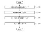
- a method of manufacturing a press-formed product according to Embodiment 2 of the present invention is to manufacture an actual press-formed product by adjusting the press-forming conditions so as to improve the dimensional accuracy of the outer peripheral shape. Then, as shown in FIG. 9, the method for manufacturing a press-formed product according to the second embodiment includes an outer peripheral shape prediction accuracy acquisition step S21, an analysis condition adjustment step S23, a press-molding condition adjustment step S25, a press-molding and step S27.
- an outer peripheral shape prediction accuracy acquisition step S21 an analysis condition adjustment step S23, a press-molding condition adjustment step S25, a press-molding and step S27.
- the outer peripheral shape prediction accuracy acquisition step S21 is the outer peripheral shape at the bottom dead center of the actual press-formed product 11 obtained by actually press-molding a blank using a mold by the method for evaluating the outer peripheral shape of the press-formed product according to the first embodiment.
- the outer peripheral shape prediction accuracy acquisition step S21 performs an elastic-plastic dynamics analysis of the process of press-molding the actual press-formed product 11 by the method according to the first embodiment, and the press-formed product analysis model 21 is formed at the bottom dead center. Find the outer shape at .
- the difference between the outer peripheral shape of the actual press-formed product 11 at the forming bottom dead center and the outer peripheral shape of the press-formed product analysis model 21 at the forming bottom dead center is calculated as the outer periphery of the press-formed product analysis model 21 at the forming bottom dead center. Calculated as shape prediction accuracy.
- FIG. 3(b)(ii) is a diagram showing the outer peripheral shape of the press-formed product work bottom dead center shape model 17 obtained as the outer peripheral shape of the actual press-formed product 11 at the forming bottom dead center.
- the outer peripheral shape of the press-formed product analysis model 21 at the molding bottom dead center can be acquired by performing the press-formed product analysis model peripheral shape acquisition step S3 according to the first embodiment described above (Fig. 3 (a)(ii)).
- the outer peripheral shape of the press-formed product work bottom dead center shape model 17 and the outer peripheral shape at the molding bottom dead center of the press-formed product analysis model 21 obtained in this way are calculated by performing alignment with the same mold model 1. It is a thing. Therefore, it is possible to compare the outer peripheral shape of the press-formed product work bottom dead center shape model 17 and the outer peripheral shape at the forming bottom dead center of the press-formed product analysis model 21. It can be obtained as the prediction accuracy of the outer peripheral shape at the dead point.
- the difference in the outer peripheral shape between the press-formed product work bottom dead center shape model 17 and the press-formed product analysis model 21 is the press-formed product analysis model 21 when the outer peripheral shape of the press-formed product work bottom dead center shape model 17 is used as a reference. It is only necessary to calculate the amount of deviation of the outer peripheral shape at the bottom dead center of forming. For example, the vertical distance (absolute value) from the outer peripheral shape of the press-formed product work bottom dead center shape model 17 to the outer peripheral shape of the press-formed product analysis model 21 at the forming bottom dead center is calculated as the divergence amount.
- the analysis condition adjustment step S23 is a press-formed product analysis in the elastic-plastic dynamic analysis of the process of press-forming the actual press-formed product 11 so as to increase the prediction accuracy of the outer peripheral shape at the forming bottom dead center of the press-formed product analysis model 21. This is the step of adjusting the analysis conditions of the model 21 .
- Analysis conditions that affect the accuracy of prediction of the outer peripheral shape at the bottom dead center of the press-formed product analysis model 21 include (i) FEM analysis conditions and (ii) press-form analysis conditions.
- FEM analysis conditions are numerical analysis methods and models for performing elastic-plastic dynamic analysis (finite element analysis) by the finite element method (FEM) as elastic-plastic dynamic analysis of the press forming process. It is an analysis condition on computing techniques related to the approximation method of .
- the FEM analysis conditions are the blank element division size (size of element divisions), the number of integral points in the element (number of integral points), the type of element to be selected, the material constitutive law of the metal material ) and the like.
- Press forming analysis conditions refer to the computational analysis conditions that are prerequisites for the elastic-plastic dynamics analysis of the press forming process. It is the physical parameter involved. Press molding analysis conditions include, for example, the bottom dead center position of the mold, the friction coefficient between the mold and the blank material, the clearance between the mold (punch and die), molding speed of the mold, and the like.
- Fig. 10(a) shows the press-forming at the forming bottom dead center obtained under the analysis conditions adjusted based on the prediction accuracy of the outer peripheral shape at the forming bottom dead center of the press-formed product analysis model 21 shown in Fig. 3(c). The result of obtaining the product analysis model 21 is shown.
- the results shown in FIG. 10(a) are obtained by adjusting the FEM analysis conditions and the press forming analysis conditions as follows.
- the average element size of the blank was subdivided from 1.5 mm to 1.2 mm, and the number of integration points in the plate thickness direction was increased from 7 points to 9 points. changed to Furthermore, the material model of the blank is converted from the isotropic hardening material model to more accurately determine the hardening properties of the metal material and the elastic behavior during unloading. changed to the Yoshida-Uemori material model that can be reproduced in
- the press forming analysis conditions are based on the state of divergence between the outer peripheral shape at the forming bottom dead center of the press formed product analysis model 21 in FIG. , the coefficient of friction between the mold model 1 and the blank was changed from 0.10 to 0.11.
- FIG. 10(c) shows the result of comparison between the outer peripheral shape of .
- the outer peripheral shape of the press-formed product analysis model 21 at the forming bottom dead center is adjusted to the outer peripheral shape of the press-formed product work bottom dead center shape model 17 by adjusting the analysis conditions as described above.
- the analysis conditions are adjusted (changed) as described above to perform an elastic-plastic dynamic analysis, and the accuracy of prediction of the outer peripheral shape at the bottom dead center of the press-formed product analysis model 21 is obtained.
- the analysis conditions may be further adjusted based on the predicted accuracy obtained.
- the press-forming condition adjustment step S25 is a step of adjusting the press-forming conditions in the elasto-plastic dynamics analysis of the process of press-forming the actual press-formed product 11 .
- the adjustment of the press forming conditions is performed by adjusting the target outer peripheral shape of the press-formed product analysis model 21 at the forming bottom dead center and the outer peripheral shape of the actual press-formed product 11 at the forming bottom dead center determined by the analysis conditions adjusted in the analysis condition adjustment step S23. is within a predetermined range.
- the adjustment of the press molding conditions in the press molding condition adjustment step S25 is performed, for example, according to the following procedures (A) to (D).
- (A) Perform elastic-plastic dynamics analysis of the process of press forming the actual press-formed product 11 under the analysis conditions adjusted in the analysis condition adjustment step S23 and the subsequent springback process, and form the press-formed product analysis model 21 Find the outer shape at the bottom dead center.
- the press-formed product analysis model outer peripheral shape acquisition step S3 may be performed by applying the adjusted analysis conditions to the press-formed product analysis model 21 .
- (B) Obtaining the deviation between the outer peripheral shape at the molding bottom dead center of the press-formed product analysis model 21 obtained under the adjusted analysis conditions and the target peripheral shape at the molding bottom dead center of the actual press-formed product 11, It is determined whether the obtained deviation is within a predetermined range.
- the predetermined range that is predetermined so that the deviation of the outer peripheral shape at the forming bottom dead center of the press-formed product analysis model 21 falls within the dimensional accuracy allowed for the actual press-formed product 11, for example. It can be set as appropriate based on the
- the press forming conditions are adjusted by, for example, changing the set position of the blank model and the shape of the blank model based on the deviation (not shown) between the outer peripheral shape at the forming bottom dead center of the press formed product analysis model 21 and the target. do it.
- the positioning holes and pins of the mold model 1 are arranged so that the set position of the blank model with respect to the mold model 1 is shifted in the direction opposite to the deviation of the outer peripheral shape from the target shape.
- the position of , etc. should be adjusted.
- the shape of the blank model before press forming may be adjusted so that the outer peripheral shape of the press-formed product analysis model changes in the direction opposite to the shift.
- the press molding conditions may be adjusted by changing the shape of the mold model 1.
- the press-molding step S27 is a step of actually press-molding the blank using a mold under the press-molding conditions adjusted in the press-molding condition adjustment step S25 to manufacture the actual press-molded product 11 .
- the press-formed product analysis model obtained by the method according to the first embodiment is used to increase the prediction accuracy of the outer peripheral shape at the forming bottom dead center. Adjust the analysis conditions to Subsequently, the deviation between the outer peripheral shape at the forming bottom dead center of the press-formed product analysis model obtained under the adjusted analysis conditions and the target peripheral shape at the forming bottom dead center of the actual press-formed product falls within a predetermined range. Adjust the press molding conditions so that it fits. By actually press-forming the actual press-formed product under the adjusted press-forming conditions, it is possible to manufacture the actual press-formed product with improved dimensional accuracy of the outer peripheral shape. As a result, it is possible to prevent troubles when assembling parts with other parts.
- the press molding conditions such as the position of the blank and the mold shape may be further adjusted based on the outer peripheral shape of the actual press-molded product press-molded under the adjusted press-molding conditions.
- the press molding conditions are adjusted so as to improve the dimensional accuracy of the outer peripheral shape. It is possible to satisfy the permissible dimensional accuracy for the outer peripheral shape of the actual press-formed product.
- the cost and period of preparation for production of the actual press-formed product 11 can be greatly reduced.
- the actual press-formed product 11 can be adjusted according to signs of changes in the outer peripheral shape during mass production, such as wear and deformation of the mold. Molding conditions can be changed. As a result, it is possible to suppress the occurrence of a large number of dimensional defects in the outer peripheral shape of the actual press-formed product 11 .
- the actual press-formed product 11 targeted in Embodiments 1 and 2 was an automobile part (A-pillar upper), but the actual press-formed product targeted by the present invention is consumer electronics parts and the like. may be
- the step S21 for acquiring the accuracy of prediction of the outer peripheral shape, the step S23 for adjusting the analysis conditions, the step S25 for adjusting the press-forming conditions, and the step S27 for press-forming of the second embodiment were performed, and the actual press-formed product 11 was produced. Press molded.
- the blank positioning hole in the mold model 1 is set as the press-forming condition so that the outer peripheral shape at the forming bottom dead center of the press-formed product analysis model 21 approaches the target shape. ) and positioning pins were adjusted.
- the target shape was the target of the outer peripheral shape of the actual press-formed product 11 at the forming bottom dead center (hereinafter referred to as "target shape").
- a mold is actually manufactured at the blank set position (positioning hole/pin) with respect to the mold model 1 whose shape is adjusted for the press molded product analysis model 21, and the manufactured mold is used. The blank was press-formed into an actual press-formed product 11 by using the
- the surface shape was measured after it was released from the mold and spring-backed, and a press-molded product work shape model 15 was created from the measured three-dimensional surface shape measurement data. Then, elastic finite element analysis of the process of sandwiching the created press-formed work shape model 15 by the mold model 1 to the bottom dead point of molding is performed, and the outer peripheral shape of the press-formed work shape model 17 at the bottom dead center of molding asked for
- the step S25 for adjusting the peripheral shape prediction accuracy and the step S23 for adjusting the analysis conditions according to the second embodiment were not performed, and the step S25 for adjusting the press forming conditions and the step S27 for press forming were performed.
- An actual press-molded product 11 was press-molded.
- the outer peripheral shape of the press-formed product analysis model 21 at the forming bottom dead center approaches the target shape.
- the press molding conditions were adjusted to Then, the actual press-formed product 11 was press-formed under the adjusted press-forming conditions.
- the press molding conditions are adjusted by changing the positions of the blank positioning holes, pins, etc. in the mold model 1 based on the outer peripheral shape at the molding bottom dead center of the press molded product analysis model 21. gone.
- the outer peripheral shape at the bottom dead center of the actual press-formed product 11 in each of the invention example and the comparative example is the ratio of the length of the outer peripheral shape at which the amount of deviation from the target shape is within ⁇ 0.5 mm (hereinafter referred to as “ ⁇ 0.5 mm It was evaluated by the "concordance rate").
- the ⁇ 0.5mm matching rate in the invention example was 95%, while the ⁇ 0.5mm matching rate in the comparative example was 65%. From this result, it was demonstrated that the method according to the present invention can improve the dimensional accuracy of the outer peripheral shape of the actual press-formed product 11 at the forming bottom dead center.
- the mold shape was repeatedly adjusted so that the ⁇ 0.5 mm matching rate of the outer peripheral shape at the bottom dead center of the actual press-molded product 11 was 100%.
- the adjustment of the mold shape was performed in the same manner as the adjustment of the press molding conditions described above.
- the matching rate of ⁇ 0.5 mm became 100% with one adjustment of the mold shape.
- the matching rate of ⁇ 0.5 mm became 100% after adjusting the mold shape three times. From this result, it was demonstrated that the method according to the present invention can achieve the allowable dimensional accuracy for the actual press-formed product 11 with a smaller number of mold shape adjustments. As a result, it was shown that the cost and period of preparation for production of actual press-formed products can be greatly reduced.
- the outer peripheral shape of the actual press-formed product that is actually press-formed, and the outer peripheral shape of the press-formed product analysis model obtained by the elastic-plastic dynamic analysis of the process of press-forming the actual press-formed product can be performed accurately with high reproducibility, and can provide a method, apparatus, and program for evaluating the outer peripheral shape of a press-formed product that can appropriately evaluate each outer peripheral shape.
- the prediction accuracy is increased based on the evaluation of the outer peripheral shape of the press-formed product analysis model, and the press forming conditions are adjusted so that the dimensional accuracy of the outer peripheral shape is improved, thereby improving the dimensional accuracy. It is possible to provide a method for manufacturing a press-formed product that manufactures an actual press-formed product that has been pressed.
Landscapes
- Engineering & Computer Science (AREA)
- Physics & Mathematics (AREA)
- Theoretical Computer Science (AREA)
- Geometry (AREA)
- General Physics & Mathematics (AREA)
- Computer Hardware Design (AREA)
- General Engineering & Computer Science (AREA)
- Evolutionary Computation (AREA)
- Computational Mathematics (AREA)
- Pure & Applied Mathematics (AREA)
- Mathematical Optimization (AREA)
- Mathematical Analysis (AREA)
- Mechanical Engineering (AREA)
- Shaping Metal By Deep-Drawing, Or The Like (AREA)
Abstract
Description
以下、本発明の実施の形態1に係るプレス成形品の外周形状評価方法、装置及びプログラムについて、図1~図7を参照して説明する。本実施の形態1では、一例として図2(a)に示す、自動車のAピラーアッパー(front pillar upper)を模擬したハット断面形状(hat-shaped cross section)の実プレス成形品11を対象とした。実プレス成形品11は、980MPa級(MPa-class)、板厚1.4mmの冷延鋼板(cold rolled steel sheet)をプレス成形したものである。また、本願の図2、図3及び図5におけるX、Y及びZは、実プレス成形品11、三次元表面形状測定データ13、プレス成形品ワーク形状モデル15、プレス成形品ワーク下死点形状モデル17及びプレス成形品解析モデル21の長手方向(X方向)、幅方向(Y方向)及び高さ方向(Z方向)を示している。
本発明の実施の形態1に係るプレス成形品の外周形状評価方法は、一例として図2に示すように、実際に金型を用いてブランクをプレス成形した実プレス成形品11の成形下死点における外周形状と、一例として図3(a)に示すように、実プレス成形品11をプレス成形する過程の弾塑性力学的解析により求めたプレス成形品解析モデル21の成形下死点における外周形状と、を比較しそれぞれを評価するものである。図1に示すように、プレス成形品の外周形状評価方法は、実プレス成形品外周形状取得ステップS1と、プレス成形品解析モデル外周形状取得ステップS3と、外周形状比較・評価ステップS5と、を含む。以下、上記の各ステップについて説明する。
実プレス成形品外周形状取得ステップS1は、実プレス成形品11を離型してスプリングバックした後の表面形状を測定して取得した三次元表面形状測定データ13からプレス成形品ワーク形状モデル15を作成し、プレス成形品ワーク形状モデル15を金型の金型モデル1によって成形下死点まで挟み込む過程の力学的解析を行い、成形下死点におけるプレス成形品ワーク下死点形状モデル17を求め、プレス成形品ワーク下死点形状モデル17の外周形状を実プレス成形品11の外周形状として取得するステップである。
プレス成形品解析モデル外周形状取得ステップS3は、ブランクのブランクモデルを金型モデル1を用いてプレス成形する過程の弾塑性力学的解析を行うことにより、図3(a)に示すように、成形下死点におけるプレス成形品解析モデル21を求め、求めたプレス成形品解析モデル21の外周形状を取得するステップである。
外周形状比較・評価ステップS5は、実プレス成形品外周形状取得ステップS1において取得した実プレス成形品11の外周形状と、プレス成形品解析モデル外周形状取得ステップS3において取得したプレス成形品解析モデル21の外周形状と、を比較し、それぞれの外周形状を評価するステップである。
実プレス成形品接触圧力分布算出ステップS7は、実プレス成形品外周形状取得ステップS1において求めた成形下死点におけるプレス成形品ワーク下死点形状モデル17に作用する金型モデル1との接触圧力分布を実プレス成形品11に作用する金型からの接触圧力分布として算出するステップである。
プレス成形品解析モデル接触圧力分布算出ステップS9は、プレス成形品解析モデル外周形状取得ステップS3において求めた成形下死点におけるプレス成形品解析モデル21に作用する金型モデル1との接触圧力分布を算出するステップである。
接触圧力分布比較・評価ステップS11は、実プレス成形品接触圧力分布算出ステップS7において算出した実プレス成形品11に作用する接触圧力分布と、プレス成形品解析モデル接触圧力分布算出ステップS9において算出したプレス成形品解析モデル21に作用する接触圧力分布と、を比較し、それぞれを評価するステップである。
本発明の実施の形態1に係るプレス成形品の外周形状評価装置31は、一例として図2、図3(b)に示すように、実際に金型を用いてブランクをプレス成形した実プレス成形品11の成形下死点における外周形状と、一例として図3(a)に示すように、実プレス成形品11をプレス成形する過程の弾塑性力学的解析により求めたプレス成形品解析モデル21の成形下死点における外周形状と、を比較しそれぞれを評価するものである。図6に示すように、プレス成形品の外周形状評価装置31は、実プレス成形品外周形状取得部33と、プレス成形品解析モデル外周形状取得部35と、外周形状比較・評価部37と、を備える。
実プレス成形品外周形状取得部33は、図2に示すように、実プレス成形品11を離型してスプリングバックした後の表面形状を測定して取得した三次元表面形状測定データからプレス成形品ワーク形状モデル15を作成し、プレス成形品ワーク形状モデル15を金型の金型モデル1によって成形下死点まで挟み込む過程の力学的解析を行い、成形下死点におけるプレス成形品ワーク下死点形状モデル17を求め、プレス成形品ワーク下死点形状モデル17の外周形状を実プレス成形品11の外周形状として取得するものである。
プレス成形品解析モデル外周形状取得部35は、ブランクのブランクモデルを金型モデル1を用いてプレス成形する過程の弾塑性力学的解析を行うことにより、図2(a)に示すように、成形下死点におけるプレス成形品解析モデル21を求め、求めたプレス成形品解析モデル21の外周形状を取得するものである。
外周形状比較・評価部37は、図3(c)に示すように、実プレス成形品外周形状取得部33により取得した実プレス成形品11の外周形状と、プレス成形品解析モデル外周形状取得部35により取得したプレス成形品解析モデル21の外周形状と、を比較し、それぞれの外周形状を評価するものである。
実プレス成形品接触圧力分布算出部43は、図5(a)に示すように、実プレス成形品外周形状取得部33において求めた成形下死点におけるプレス成形品ワーク下死点形状モデル17に作用する金型モデル1との接触圧力分布を実プレス成形品11に作用する金型からの接触圧力分布として算出するものである。
プレス成形品解析モデル接触圧力分布算出部45は、図5(b)に示すように、プレス成形品解析モデル外周形状取得部35により求めた成形下死点におけるプレス成形品解析モデル21に作用する金型モデル1との接触圧力分布を算出するものである。
接触圧力分布比較・評価部47は、実プレス成形品接触圧力分布算出部43により算出した実プレス成形品11に作用する接触圧力分布と、プレス成形品解析モデル接触圧力分布算出部45により算出したプレス成形品解析モデル21に作用する接触圧力分布と、を比較し、それぞれを評価するものである。
本発明の実施の形態1は、プレス成形品の外周形状評価プログラムとして構成することができる。すなわち、本発明の実施の形態1に係るプレス成形品の外周形状評価プログラムは、実際に金型を用いてブランクをプレス成形した実プレス成形品の外周形状と、実プレス成形品をプレス成形する過程の弾塑性力学的解析により求めたプレス成形品解析モデルの外周形状と、を比較しそれぞれを評価するものである。図6に示すように、プレス成形品の外周形状評価プログラムは、コンピュータを、実プレス成形品外周形状取得部33と、プレス成形品解析モデル外周形状取得部35と、外周形状比較・評価部37と、として機能させる。
<プレス成形品の製造方法>
本発明の実施の形態2に係るプレス成形品の製造方法は、外周形状の寸法精度が向上するようにプレス成形条件を調整して実プレス成形品を製造するものである。そして、本実施の形態2に係るプレス成形品の製造方法は、図9に示すように、外周形状予測精度取得ステップS21と、解析条件調整ステップS23と、プレス成形条件調整ステップS25と、プレス成形ステップS27と、を含む。以下、一例として図2に示す実プレス成形品11を対象として、上記の各ステップについて説明する。
外周形状予測精度取得ステップS21は、実施の形態1に係るプレス成形品の外周形状評価方法により、実際に金型を用いてブランクをプレス成形した実プレス成形品11の成形下死点における外周形状を求める。さらに、外周形状予測精度取得ステップS21は、実施の形態1に係る方法により、実プレス成形品11をプレス成形する過程の弾塑性力学的解析を行い、プレス成形品解析モデル21の成形下死点における外周形状を求める。そして、実プレス成形品11の成形下死点における外周形状と、プレス成形品解析モデル21の成形下死点における外周形状と、の差異を、プレス成形品解析モデル21の成形下死点における外周形状の予測精度として求める。
解析条件調整ステップS23は、プレス成形品解析モデル21の成形下死点における外周形状の予測精度を高めるように、実プレス成形品11をプレス成形する過程の弾塑性力学的解析におけるプレス成形品解析モデル21の解析条件を調整するステップである。
プレス成形条件調整ステップS25は、実プレス成形品11をプレス成形する過程の弾塑性力学的解析におけるプレス成形条件を調整するステップである。プレス成形条件の調整は、解析条件調整ステップS23で調整した解析条件で求められるプレス成形品解析モデル21の成形下死点における外周形状と実プレス成形品11の成形下死点における外周形状の目標との偏差が予め定めた所定の範囲内に収まるように行う。
(B)調整した解析条件の下で求めたプレス成形品解析モデル21の成形下死点における外周形状と、実プレス成形品11の成形下死点における外周形状の目標と、の偏差を求め、該求めた偏差が予め定めた所定の範囲内に収まっているかどうかを判定する。
(C)偏差が予め定めた所定の範囲内に収まっていないと判定された場合、プレス成形品解析モデル21を用いてプレス成形する過程とその後のスプリングバックする過程との弾塑性力学的解析におけるプレス成形条件を調整する。
(D)調整したプレス成形条件の下で求めたプレス成形品解析モデル21の成形下死点における外周形状の偏差が予め定めた所定の範囲内に収まるまで、上記の(A)~(C)を繰り返す。
プレス成形ステップS27は、プレス成形条件調整ステップS25で調整したプレス成形条件の下で実際に金型を用いてブランクをプレス成形し、実プレス成形品11を製造するステップである。
3 下型モデル
5 上型モデル
11 実プレス成形品
13 三次元表面形状測定データ
15 プレス成形品ワーク形状モデル
17 プレス成形品ワーク下死点形状モデル
17a パンチ底部
17b フランジ部
21 プレス成形品解析モデル
21a パンチ底部
21b フランジ部
31 外周形状評価装置
33 実プレス成形品外周形状取得部
35 プレス成形品解析モデル外周形状取得部
37 外周形状比較・評価部
41 外周形状評価装置
43 実プレス成形品接触圧力分布算出部
45 プレス成形品解析モデル接触圧力分布算出部
47 接触圧力分布比較・評価部
Claims (10)
- 実際に金型を用いてブランクをプレス成形した実プレス成形品の外周形状と、前記実プレス成形品をプレス成形する過程の弾塑性力学的解析により求めたプレス成形品解析モデルの外周形状と、を比較しそれぞれを評価するプレス成形品の外周形状評価方法であって、
前記実プレス成形品を離型してスプリングバックした後の表面形状を測定して取得した三次元表面形状測定データからプレス成形品ワーク形状モデルを作成し、該プレス成形品ワーク形状モデルを前記金型の金型モデルによって成形下死点まで挟み込む過程の力学的解析を行い、成形下死点におけるプレス成形品ワーク下死点形状モデルを求め、該求めたプレス成形品ワーク下死点形状モデルの外周形状を前記実プレス成形品の外周形状として取得する実プレス成形品外周形状取得ステップと、
前記ブランクのブランクモデルを前記金型モデルを用いてプレス成形する過程の弾塑性力学的解析を単一工程又は複数工程にわたって行うことにより、成形下死点におけるプレス成形品解析モデルを求め、該求めたプレス成形品解析モデルの外周形状を取得するプレス成形品解析モデル外周形状取得ステップと、
前記実プレス成形品外周形状取得ステップにおいて取得した前記実プレス成形品の外周形状と、前記プレス成形品解析モデル外周形状取得ステップにおいて取得した前記プレス成形品解析モデルの外周形状と、を比較し、それぞれの外周形状を評価する外周形状比較・評価ステップと、
を含む、プレス成形品の外周形状評価方法。 - 前記実プレス成形品外周形状取得ステップにおける前記力学的解析は弾性有限要素解析又は弾塑性有限要素解析であり、
前記プレス成形品解析モデル外周形状取得ステップにおける前記弾塑性力学的解析は、弾塑性有限要素解析である、請求項1に記載のプレス成形品の外周形状評価方法。 - 前記実プレス成形品をプレス成形する過程が該実プレス成形品の部位ごとに成形工程が分かれている場合において、
前記実プレス成形品外周形状取得ステップにおける前記金型モデルは、前記実プレス成形品の各部位を成形する各金型の金型モデルを合成して一つの金型モデルとしたものである、請求項1又は2に記載のプレス成形品の外周形状評価方法。 - 前記実プレス成形品外周形状取得ステップにおいて求めた前記プレス成形品ワーク下死点形状モデルに作用する前記金型モデルとの接触圧力分布を前記実プレス成形品に作用する前記金型からの接触圧力分布として算出する実プレス成形品接触圧力分布算出ステップと、
前記プレス成形品解析モデル外周形状取得ステップにおいて求めた成形下死点における前記プレス成形品解析モデルに作用する前記金型モデルとの接触圧力分布を算出するプレス成形品解析モデル接触圧力分布算出ステップと、
前記実プレス成形品接触圧力分布算出ステップにおいて算出した前記実プレス成形品に作用する接触圧力分布と、前記プレス成形品解析モデル接触圧力分布算出ステップにおいて算出された前記プレス成形品解析モデルに作用する接触圧力分布と、を比較し、それぞれを評価する接触圧力分布比較・評価ステップと、
をさらに含む、請求項1又は2に記載のプレス成形品の外周形状評価方法。 - 前記実プレス成形品外周形状取得ステップにおいて求めた前記プレス成形品ワーク下死点形状モデルに作用する前記金型モデルとの接触圧力分布を前記実プレス成形品に作用する前記金型からの接触圧力分布として算出する実プレス成形品接触圧力分布算出ステップと、
前記プレス成形品解析モデル外周形状取得ステップにおいて求めた成形下死点における前記プレス成形品解析モデルに作用する前記金型モデルとの接触圧力分布を算出するプレス成形品解析モデル接触圧力分布算出ステップと、
前記実プレス成形品接触圧力分布算出ステップにおいて算出した前記実プレス成形品に作用する接触圧力分布と、前記プレス成形品解析モデル接触圧力分布算出ステップにおいて算出された前記プレス成形品解析モデルに作用する接触圧力分布と、を比較し、それぞれを評価する接触圧力分布比較・評価ステップと、
をさらに含む、請求項3に記載のプレス成形品の外周形状評価方法。 - 実際に金型を用いてブランクをプレス成形した実プレス成形品の外周形状と、前記実プレス成形品をプレス成形する過程の弾塑性力学的解析により求めたプレス成形品解析モデルの外周形状と、を比較しそれぞれを評価するプレス成形品の外周形状評価装置であって、
前記実プレス成形品を離型してスプリングバックした後の表面形状を測定して取得した三次元表面形状測定データからプレス成形品ワーク形状モデルを作成し、該プレス成形品ワーク形状モデルを前記金型の金型モデルによって成形下死点まで挟み込む過程の力学的解析を行い、成形下死点におけるプレス成形品ワーク下死点形状モデルを求め、該求めたプレス成形品ワーク下死点形状モデルの外周形状を前記実プレス成形品の外周形状として取得する実プレス成形品外周形状取得部と、
前記ブランクのブランクモデルを前記金型モデルを用いてプレス成形する過程の弾塑性力学的解析を単一工程又は複数工程にわたって行うことにより、成形下死点におけるプレス成形品解析モデルを求め、該求めたプレス成形品解析モデルの外周形状を取得するプレス成形品解析モデル外周形状取得部と、
前記実プレス成形品外周形状取得部により取得した前記実プレス成形品の外周形状と、前記プレス成形品解析モデル外周形状取得部により取得した前記プレス成形品解析モデルの外周形状と、を比較し、それぞれの外周形状を評価する外周形状比較・評価部と、
を備える、プレス成形品の外周形状評価装置。 - 前記実プレス成形品外周形状取得部において求めた前記プレス成形品ワーク下死点形状モデルに作用する前記金型モデルとの接触圧力分布を前記実プレス成形品に作用する前記金型からの接触圧力分布として算出する実プレス成形品接触圧力分布算出部と、
前記プレス成形品解析モデル外周形状取得部により求めた成形下死点における前記プレス成形品解析モデルに作用する前記金型モデルとの接触圧力分布を算出するプレス成形品解析モデル接触圧力分布算出部と、
前記実プレス成形品接触圧力分布算出部により算出した前記実プレス成形品に作用する接触圧力分布と、前記プレス成形品解析モデル接触圧力分布算出部により算出した前記プレス成形品解析モデルに作用する接触圧力分布と、を比較し、それぞれを評価する接触圧力分布比較・評価部と、
をさらに備える、請求項6に記載のプレス成形品の外周形状評価装置。 - 実際に金型を用いてブランクをプレス成形した実プレス成形品の外周形状と、前記実プレス成形品をプレス成形する過程の弾塑性力学的解析により求めたプレス成形品解析モデルの外周形状と、を比較しそれぞれを評価するプレス成形品の外周形状評価プログラムであって、
コンピュータを、
前記実プレス成形品を離型してスプリングバックした後の表面形状を測定して取得した三次元表面形状測定データからプレス成形品ワーク形状モデルを作成し、該プレス成形品ワーク形状モデルを前記金型の金型モデルによって成形下死点まで挟み込む過程の力学的解析を行い、成形下死点におけるプレス成形品ワーク下死点形状モデルを求め、該求めたプレス成形品ワーク下死点形状モデルの外周形状を前記実プレス成形品の外周形状として取得する実プレス成形品外周形状取得部と、
前記ブランクのブランクモデルを前記金型モデルを用いてプレス成形する過程の弾塑性力学的解析を単一工程又は複数工程にわたって行うことにより、成形下死点におけるプレス成形品解析モデルを求め、該求めたプレス成形品解析モデルの外周形状を取得するプレス成形品解析モデル外周形状取得部と、
前記実プレス成形品外周形状取得部により取得した前記実プレス成形品の外周形状と、前記プレス成形品解析モデル外周形状取得部により取得した前記プレス成形品解析モデルの外周形状と、を比較し、それぞれの外周形状を評価する外周形状比較・評価部と、
として機能させる、プレス成形品の外周形状評価プログラム。 - 前記コンピュータを、さらに、
前記実プレス成形品外周形状取得部において求めた前記プレス成形品ワーク下死点形状モデルに作用する前記金型モデルとの接触圧力分布を前記実プレス成形品に作用する前記金型からの接触圧力分布として算出する実プレス成形品接触圧力分布算出部と、
前記プレス成形品解析モデル外周形状取得部により求めた成形下死点における前記プレス成形品解析モデルに作用する前記金型モデルとの接触圧力分布を算出するプレス成形品解析モデル接触圧力分布算出部と、
前記実プレス成形品接触圧力分布算出部により算出した前記実プレス成形品に作用する接触圧力分布と、前記プレス成形品解析モデル接触圧力分布算出部により算出した前記プレス成形品解析モデルに作用する接触圧力分布と、を比較し、それぞれを評価する接触圧力分布比較・評価部と、
として機能させる、請求項8に記載のプレス成形品の外周形状評価プログラム。 - 外周形状の寸法精度が向上するようにプレス成形条件を調整して実プレス成形品を製造するプレス成形品の製造方法であって、
請求項1に記載のプレス成形品の外周形状評価方法に基づいて、前記実プレス成形品をプレス成形する過程の弾塑性力学的解析により求めたプレス成形品解析モデルの成形下死点における外周形状と、実際に金型を用いてブランクをプレス成形した実プレス成形品の成形下死点における外周形状との差異を、前記プレス成形品解析モデルの成形下死点における外周形状の予測精度として求める外周形状予測精度取得ステップと、
前記プレス成形品解析モデルの外周形状の予測精度に基づき、前記実プレス成形品をプレス成形する過程の弾塑性力学的解析における前記プレス成形品解析モデルの解析条件を調整する解析条件調整ステップと、
該調整した解析条件で求められる前記プレス成形品解析モデルの成形下死点における外周形状と、前記実プレス成形品の成形下死点における外周形状の目標と、の偏差が所定の範囲に収まるように、前記実プレス成形品をプレス成形する過程の弾塑性力学的解析におけるプレス成形条件を調整するプレス成形条件調整ステップと、
前記プレス成形条件調整ステップで調整したプレス成形条件にて、実際に金型を用いてブランクをプレス成形し、実プレス成形品を製造するプレス成形ステップと、
を含む、プレス成形品の製造方法。
Priority Applications (5)
| Application Number | Priority Date | Filing Date | Title |
|---|---|---|---|
| MX2024008354A MX2024008354A (es) | 2022-01-11 | 2022-12-13 | Metodo, dispositivo y programa de evaluacion de la forma periferica de una pieza conformada en prensa, y metodo de fabricacion de una pieza conformada en prensa. |
| EP22920542.2A EP4439372A4 (en) | 2022-01-11 | 2022-12-13 | Method, apparatus and program for evaluating the peripheral shape of a compression-molded article and method for producing a compression-molded article |
| KR1020247022087A KR20240113840A (ko) | 2022-01-11 | 2022-12-13 | 프레스 성형품의 외주 형상 평가 방법, 장치 및 프로그램, 그리고 프레스 성형품의 제조 방법 |
| CN202280088474.9A CN118647999A (zh) | 2022-01-11 | 2022-12-13 | 冲压成型件的外周形状评价方法、装置和程序以及冲压成型件的制造方法 |
| US18/720,757 US20250050403A1 (en) | 2022-01-11 | 2022-12-13 | Method, device, and program of evaluating peripheral shape of press formed part, and method of manufacturing press formed part |
Applications Claiming Priority (4)
| Application Number | Priority Date | Filing Date | Title |
|---|---|---|---|
| JP2022-002024 | 2022-01-11 | ||
| JP2022002024 | 2022-01-11 | ||
| JP2022172881A JP7306558B1 (ja) | 2022-01-11 | 2022-10-28 | プレス成形品の外周形状評価方法、装置及びプログラム、並びにプレス成形品の製造方法 |
| JP2022-172881 | 2022-10-28 |
Publications (1)
| Publication Number | Publication Date |
|---|---|
| WO2023136024A1 true WO2023136024A1 (ja) | 2023-07-20 |
Family
ID=87072530
Family Applications (1)
| Application Number | Title | Priority Date | Filing Date |
|---|---|---|---|
| PCT/JP2022/045840 Ceased WO2023136024A1 (ja) | 2022-01-11 | 2022-12-13 | プレス成形品の外周形状評価方法、装置及びプログラム、並びにプレス成形品の製造方法 |
Country Status (7)
| Country | Link |
|---|---|
| US (1) | US20250050403A1 (ja) |
| EP (1) | EP4439372A4 (ja) |
| JP (1) | JP7306558B1 (ja) |
| KR (1) | KR20240113840A (ja) |
| CN (1) | CN118647999A (ja) |
| MX (1) | MX2024008354A (ja) |
| WO (1) | WO2023136024A1 (ja) |
Families Citing this family (1)
| Publication number | Priority date | Publication date | Assignee | Title |
|---|---|---|---|---|
| WO2021182334A1 (ja) * | 2020-03-09 | 2021-09-16 | 公立大学法人大阪 | 線状加熱による金属板の曲げ加工に用いる加熱方案の算出方法 |
Citations (3)
| Publication number | Priority date | Publication date | Assignee | Title |
|---|---|---|---|---|
| JP2005266894A (ja) * | 2004-03-16 | 2005-09-29 | Suzuki Motor Corp | 金型設計支援システム及び方法並びに金型設計支援用プログラム |
| JP2009178718A (ja) * | 2008-01-29 | 2009-08-13 | Ihi Corp | 機差模擬プレス |
| JP2011133921A (ja) * | 2009-12-22 | 2011-07-07 | Hitachi Ltd | 金型表面形状の設計支援方法 |
Family Cites Families (3)
| Publication number | Priority date | Publication date | Assignee | Title |
|---|---|---|---|---|
| JP5834698B2 (ja) * | 2011-09-26 | 2015-12-24 | Jfeスチール株式会社 | プレス成形におけるスプリングバック要因分析方法及び装置 |
| JP6519639B1 (ja) * | 2017-12-07 | 2019-05-29 | Jfeスチール株式会社 | スプリングバック量変動要因部位特定方法 |
| JP6683269B1 (ja) * | 2019-02-01 | 2020-04-15 | Jfeスチール株式会社 | スプリングバック量変動要因部位特定方法 |
-
2022
- 2022-10-28 JP JP2022172881A patent/JP7306558B1/ja active Active
- 2022-12-13 KR KR1020247022087A patent/KR20240113840A/ko active Pending
- 2022-12-13 CN CN202280088474.9A patent/CN118647999A/zh active Pending
- 2022-12-13 MX MX2024008354A patent/MX2024008354A/es unknown
- 2022-12-13 EP EP22920542.2A patent/EP4439372A4/en active Pending
- 2022-12-13 WO PCT/JP2022/045840 patent/WO2023136024A1/ja not_active Ceased
- 2022-12-13 US US18/720,757 patent/US20250050403A1/en active Pending
Patent Citations (3)
| Publication number | Priority date | Publication date | Assignee | Title |
|---|---|---|---|---|
| JP2005266894A (ja) * | 2004-03-16 | 2005-09-29 | Suzuki Motor Corp | 金型設計支援システム及び方法並びに金型設計支援用プログラム |
| JP2009178718A (ja) * | 2008-01-29 | 2009-08-13 | Ihi Corp | 機差模擬プレス |
| JP2011133921A (ja) * | 2009-12-22 | 2011-07-07 | Hitachi Ltd | 金型表面形状の設計支援方法 |
Non-Patent Citations (2)
| Title |
|---|
| PLASTICITY AND PROCESSING, vol. 59, no. 689, pages 107 - 113 |
| See also references of EP4439372A4 |
Also Published As
| Publication number | Publication date |
|---|---|
| KR20240113840A (ko) | 2024-07-23 |
| JP2023102256A (ja) | 2023-07-24 |
| EP4439372A1 (en) | 2024-10-02 |
| EP4439372A4 (en) | 2025-03-19 |
| MX2024008354A (es) | 2024-07-19 |
| CN118647999A (zh) | 2024-09-13 |
| JP7306558B1 (ja) | 2023-07-11 |
| US20250050403A1 (en) | 2025-02-13 |
Similar Documents
| Publication | Publication Date | Title |
|---|---|---|
| CN111432952B (zh) | 回弹量变动原因部位确定方法 | |
| JP7276584B1 (ja) | プレス成形品のスプリングバック量評価方法、装置及びプログラム、並びにプレス成形品の製造方法 | |
| JP6683269B1 (ja) | スプリングバック量変動要因部位特定方法 | |
| KR20150107805A (ko) | 프레스 성형 해석 방법 | |
| CN113727790A (zh) | 回弹量偏差主因部位确定方法及装置 | |
| JP7306558B1 (ja) | プレス成形品の外周形状評価方法、装置及びプログラム、並びにプレス成形品の製造方法 | |
| KR20250034442A (ko) | 응력-변형 관계 추정 방법 및 스프링백 예측 방법, 그리고 프레스 성형품의 제조 방법 | |
| CN107729661B (zh) | 汽车覆盖件曲面拉伸翻边回弹控制方法 | |
| US12318831B2 (en) | Controllable and adjustable stamping draw bead with reverse bead geometry | |
| CN113853605B (zh) | 回弹量偏差主因部位确定方法及装置 | |
| JP7533491B2 (ja) | プレス成形品のスプリングバック量評価方法、装置及びプログラム | |
| JP3979492B2 (ja) | コンピュータシミュレーションによるプレス部品の成形解析法及びプレス部品を含む構造体の特性解析法 | |
| JP7533495B2 (ja) | プレス成形品の外周形状評価方法、装置及びプログラム | |
| KR20250130825A (ko) | 프레스 성형 시뮬레이션 해석 방법, 장치 및 프로그램, 그리고 프레스 성형품의 제조 방법 | |
| JP3979493B2 (ja) | コンピュータシミュレーションによるプレス部品の成形解析法及びプレス部品を含む構造体の特性解析法 | |
| US12629740B2 (en) | Method, device, and program of evaluating springback amount of press formed part, and method of manufacturing press formed part | |
| CN104226766A (zh) | 一种板材冲压不平衡流动回弹特性的评价方法及装置 | |
| CN120202075A (zh) | 冲压成型件的形状变化预测方法、装置及程序、冲压成型件的制造方法 | |
| JPWO2024038850A5 (ja) | ||
| Peinado-Asensi et al. | Towards a hybrid twin model to obtain the formability of a car body part in real time | |
| CN121289336A (zh) | 一种冷冲压件曲面翻边回弹的控制方法 | |
| CN120597443A (zh) | 模具的确定方法、装置、设备及存储介质 | |
| CN114323891A (zh) | 一种辊冲成形变宽度特征成形极限的模具及评估方法 |
Legal Events
| Date | Code | Title | Description |
|---|---|---|---|
| 121 | Ep: the epo has been informed by wipo that ep was designated in this application |
Ref document number: 22920542 Country of ref document: EP Kind code of ref document: A1 |
|
| WWE | Wipo information: entry into national phase |
Ref document number: 18720757 Country of ref document: US |
|
| WWE | Wipo information: entry into national phase |
Ref document number: 202417048924 Country of ref document: IN |
|
| WWE | Wipo information: entry into national phase |
Ref document number: MX/A/2024/008354 Country of ref document: MX |
|
| ENP | Entry into the national phase |
Ref document number: 20247022087 Country of ref document: KR Kind code of ref document: A |
|
| ENP | Entry into the national phase |
Ref document number: 2022920542 Country of ref document: EP Effective date: 20240628 |
|
| WWE | Wipo information: entry into national phase |
Ref document number: 202280088474.9 Country of ref document: CN Ref document number: 2401004536 Country of ref document: TH |
|
| NENP | Non-entry into the national phase |
Ref country code: DE |