WO2023136101A1 - 金属基複合材料の製造方法 - Google Patents
金属基複合材料の製造方法 Download PDFInfo
- Publication number
- WO2023136101A1 WO2023136101A1 PCT/JP2022/047659 JP2022047659W WO2023136101A1 WO 2023136101 A1 WO2023136101 A1 WO 2023136101A1 JP 2022047659 W JP2022047659 W JP 2022047659W WO 2023136101 A1 WO2023136101 A1 WO 2023136101A1
- Authority
- WO
- WIPO (PCT)
- Prior art keywords
- reinforcing material
- mold
- composite material
- casting
- matrix composite
- Prior art date
- Legal status (The legal status is an assumption and is not a legal conclusion. Google has not performed a legal analysis and makes no representation as to the accuracy of the status listed.)
- Ceased
Links
Images


Classifications
-
- B—PERFORMING OPERATIONS; TRANSPORTING
- B22—CASTING; POWDER METALLURGY
- B22D—CASTING OF METALS; CASTING OF OTHER SUBSTANCES BY THE SAME PROCESSES OR DEVICES
- B22D18/00—Pressure casting; Vacuum casting
- B22D18/02—Pressure casting making use of mechanical pressure devices, e.g. cast-forging
-
- B—PERFORMING OPERATIONS; TRANSPORTING
- B22—CASTING; POWDER METALLURGY
- B22D—CASTING OF METALS; CASTING OF OTHER SUBSTANCES BY THE SAME PROCESSES OR DEVICES
- B22D19/00—Casting in, on, or around objects which form part of the product
- B22D19/0081—Casting in, on, or around objects which form part of the product pretreatment of the insert, e.g. for enhancing the bonding between insert and surrounding cast metal
-
- B—PERFORMING OPERATIONS; TRANSPORTING
- B22—CASTING; POWDER METALLURGY
- B22D—CASTING OF METALS; CASTING OF OTHER SUBSTANCES BY THE SAME PROCESSES OR DEVICES
- B22D19/00—Casting in, on, or around objects which form part of the product
- B22D19/02—Casting in, on, or around objects which form part of the product for making reinforced articles
-
- B—PERFORMING OPERATIONS; TRANSPORTING
- B22—CASTING; POWDER METALLURGY
- B22D—CASTING OF METALS; CASTING OF OTHER SUBSTANCES BY THE SAME PROCESSES OR DEVICES
- B22D19/00—Casting in, on, or around objects which form part of the product
- B22D19/14—Casting in, on, or around objects which form part of the product the objects being filamentary or particulate in form
-
- B—PERFORMING OPERATIONS; TRANSPORTING
- B22—CASTING; POWDER METALLURGY
- B22D—CASTING OF METALS; CASTING OF OTHER SUBSTANCES BY THE SAME PROCESSES OR DEVICES
- B22D21/00—Casting non-ferrous metals or metallic compounds so far as their metallurgical properties are of importance for the casting procedure; Selection of compositions therefor
- B22D21/002—Castings of light metals
- B22D21/007—Castings of light metals with low melting point, e.g. Al 659 degrees C, Mg 650 degrees C
-
- B—PERFORMING OPERATIONS; TRANSPORTING
- B22—CASTING; POWDER METALLURGY
- B22D—CASTING OF METALS; CASTING OF OTHER SUBSTANCES BY THE SAME PROCESSES OR DEVICES
- B22D21/00—Casting non-ferrous metals or metallic compounds so far as their metallurgical properties are of importance for the casting procedure; Selection of compositions therefor
- B22D21/02—Casting exceedingly oxidisable non-ferrous metals, e.g. in inert atmosphere
- B22D21/04—Casting aluminium or magnesium
-
- C—CHEMISTRY; METALLURGY
- C22—METALLURGY; FERROUS OR NON-FERROUS ALLOYS; TREATMENT OF ALLOYS OR NON-FERROUS METALS
- C22C—ALLOYS
- C22C1/00—Making non-ferrous alloys
- C22C1/10—Alloys containing non-metals
- C22C1/1036—Alloys containing non-metals starting from a melt
-
- C—CHEMISTRY; METALLURGY
- C22—METALLURGY; FERROUS OR NON-FERROUS ALLOYS; TREATMENT OF ALLOYS OR NON-FERROUS METALS
- C22C—ALLOYS
- C22C1/00—Making non-ferrous alloys
- C22C1/10—Alloys containing non-metals
- C22C1/1036—Alloys containing non-metals starting from a melt
- C22C1/1073—Infiltration or casting under mechanical pressure, e.g. squeeze casting
-
- C—CHEMISTRY; METALLURGY
- C22—METALLURGY; FERROUS OR NON-FERROUS ALLOYS; TREATMENT OF ALLOYS OR NON-FERROUS METALS
- C22C—ALLOYS
- C22C32/00—Non-ferrous alloys containing at least 5% by weight but less than 50% by weight of oxides, carbides, borides, nitrides, silicides or other metal compounds, e.g. oxynitrides, sulfides, whether added as such or formed in situ
- C22C32/0047—Non-ferrous alloys containing at least 5% by weight but less than 50% by weight of oxides, carbides, borides, nitrides, silicides or other metal compounds, e.g. oxynitrides, sulfides, whether added as such or formed in situ with carbides, nitrides, borides or silicides as the main non-metallic constituents
-
- C—CHEMISTRY; METALLURGY
- C22—METALLURGY; FERROUS OR NON-FERROUS ALLOYS; TREATMENT OF ALLOYS OR NON-FERROUS METALS
- C22C—ALLOYS
- C22C32/00—Non-ferrous alloys containing at least 5% by weight but less than 50% by weight of oxides, carbides, borides, nitrides, silicides or other metal compounds, e.g. oxynitrides, sulfides, whether added as such or formed in situ
- C22C32/0084—Non-ferrous alloys containing at least 5% by weight but less than 50% by weight of oxides, carbides, borides, nitrides, silicides or other metal compounds, e.g. oxynitrides, sulfides, whether added as such or formed in situ carbon or graphite as the main non-metallic constituent
Definitions
- the present invention relates to a method for producing a metal matrix composite material, and by using the same mold for a series of steps, it is possible to easily achieve a near-net shape with high dimensional accuracy and a high reinforcement volume ratio (Vf%). It relates to a technology for manufacturing a metal matrix composite material that makes it possible to obtain a metal matrix composite material having More specifically, when using a porous reinforcing material compact/filler made of a reinforcing material such as ceramic particles and combining a matrix material made of a pure metal or alloy with the reinforcing material, the reinforcing material compact/filler
- the mold used in the molding process of is placed in the outer shell mold for casting the composite material with the molded reinforcing material molded body / filling body in place, and the reinforcing material molded body / filling body is porous It relates to a technology for manufacturing metal matrix composite materials, which is also used when impregnating and filling a molten matrix material into a metal matrix composite.
- a metal matrix composite material containing a metal such as aluminum or an aluminum alloy as a matrix material and containing ceramic particles, graphite particles, metal particles different from the matrix material, etc. as a reinforcing material is superior to the matrix material. It has excellent properties such as specific strength, specific stiffness, and thermal properties. Therefore, metal matrix composite materials are used in various industrial fields.
- a method for manufacturing a metal matrix composite material for example, there is the following first manufacturing method.
- a reinforcing material molding die (mold A) is used in advance to form a porous reinforcing material molded body, the obtained reinforcing material molded body is removed from the mold A, and the reinforcing material is molded. After preheating the body, it is placed in another casting mold B, cast using a molten matrix material (molten metal), and impregnated and filled with the molten metal into the pores (voids) of the reinforcing material molded body. compound.
- molten matrix material molten metal
- the reinforcing material molding prepared using the mold A It is necessary to insert and install the body into the recess of the casting mold of the mold B having substantially the same size and shape as the reinforcing material molded body and cast.
- the more you aim for a near-net shape with high dimensional accuracy the more difficult it becomes to insert and fit the molded reinforcing material into the recess of the casting mold.
- the molded body is damaged or chipped.
- the reinforcing material molded body and the casting mold are preheated. temperature must be increased.
- ceramics and graphite which are generally used as reinforcing materials, have a small coefficient of thermal expansion, while the mold for casting has a large coefficient of thermal expansion. Therefore, it becomes difficult to insert and fit the molded reinforcing material into a mold for casting. For this reason, in the first manufacturing method described above, it was not possible to cast a near-net shape metal matrix composite material with high dimensional accuracy.
- the second manufacturing method reinforcing material particles and short fibers are dispersed in a matrix material to prepare a reinforcing material dispersed matrix composite material in which the reinforcing material is dispersed in advance, and the obtained reinforcing material dispersed matrix composite material is dissolved. Then, the metal matrix composite material is produced by filling a mold for casting with the concave portion of the mold having a precise near-net shape by a casting method such as die casting.
- the technique described in Patent Document 1 relates to the above-described second manufacturing method using a prefabricated matrix material in which a reinforcing material is dispersed (reinforcing material dispersed matrix composite material). According to this technique, it is possible to manufacture a near-net shape metal matrix composite material close to the final shape.
- a prefabricated reinforcing material-dispersed matrix composite material in which the reinforcing material is dispersed is used, and the reinforcing material-dispersed matrix composite material in a molten state is placed in the recess of a near-net shape mold with high dimensional accuracy. Since it can be filled, it is thought that near-net molding equivalent to that of a mold will be possible.
- the alumina particle-dispersed aluminum-based composite material used in Example 1 has a reinforcement volume ratio (Vf%) of 20%
- the alumina particle-dispersed aluminum-based composite material used in Example 2 is The reinforcing material volume ratio (Vf %) is 12%, and depending on these materials, it is only possible to obtain a metal matrix composite material with a low reinforcing material volume ratio (Vf %). That is, the technique described above is not a technique for producing a metal matrix composite material with a high Vf % reinforcement.
- an object of the present invention is to provide a method for producing a metal matrix composite material that can easily obtain a metal matrix composite material having a near-net shape with high dimensional accuracy and a high reinforcement volume fraction (Vf%). It is to be.
- An object of the present invention is to preferably provide a simple manufacturing technique that can easily obtain a near-net shape metal matrix composite material having a reinforcement volume fraction (Vf %) exceeding 40%.
- a matrix material that is a pure metal or alloy such as aluminum or an aluminum alloy, and a reinforcing material made of at least one material selected from the group consisting of ceramic particles, graphite particles and metal particles different from the matrix material A method for producing a metal matrix composite material by compositing to obtain a metal matrix composite material having a near-net shape with high dimensional accuracy and a high reinforcement volume fraction (Vf%), In the step of forming a reinforcing material molded body/filler for producing a near-net shaped reinforcing material molded body or a reinforcing material filled body having pores inside using the reinforcing material, near-net-shaped spaces (recesses) are formed inside.
- a mold having a reinforcing material compact/filler formed by filling a material containing the reinforcing material in the mold to be formed to form a reinforcing material compact/filler in the mold. is preheated in the preheating step, the mold containing the preheated reinforcing material molded body / filler is placed in the outer shell mold for casting the composite material, and the reinforcing material contained in the mold is molded
- a method for producing a metal matrix composite material characterized in that the same mold is also used in a series of steps of the casting step and the casting step.
- Preferred embodiments of the method for producing the metal matrix composite material of the present invention are as follows. [2] The method for producing a metal matrix composite material according to [1] above, wherein the reinforcing material volume fraction (Vf %) exceeds 40%. [3] In the step of molding the reinforcing material molded body/filling body, a material containing at least the reinforcing material is filled in the mold in which a near-net-shaped space (recess) is formed inside, and the material is The mold in the filled state is also used, and the material filled in the mold is pressure-molded, or the mold is put in a heating furnace and filled in the mold.
- the reinforcing material is at least one selected from the group consisting of aluminum borate particles, silicon carbide particles, alumina particles, SiC particles, graphite particles, Si particles and Al Ni particles. 4], the method for producing a metal matrix composite material according to any one of
- a method for producing a metal matrix composite material that can easily obtain a metal matrix composite material having a near-net shape with high dimensional accuracy and a high Vf% of the reinforcing material is realized.
- a metal matrix composite material with a near-net shape with high dimensional accuracy and a high reinforcement volume ratio (Vf%) exceeding 40% by a simple manufacturing method. become.
- a mold having a near-net shape concave portion used for molding the reinforcing material molded body/filler is inserted into the outer shell metal for composite material casting with the reinforcing material molded body/filled body inserted.
- the technique of the present invention does not require the above-mentioned work itself, so no damage or loss occurs in the reinforcing material compact/filler. . Therefore, according to the technique of the present invention, it is possible to economically obtain a near-net shape metal matrix composite material with a high yield and high dimensional accuracy. , is extremely useful.
- FIG. 1 is a schematic diagram for explaining a mold 1;
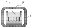
- FIG. FIG. 1B is a schematic diagram for explaining a reinforcing material-filled dual-use mold 3 in a state in which the concave portion of the mold 1 shown in FIG. 1A is filled with a reinforcing material.
- 1B is a schematic diagram for explaining a state in which the reinforcing material-filled dual-use mold 3 shown in FIG. 1B is placed in the heating furnace 10.
- FIG. 1C is a schematic diagram for explaining a state in which the preheated reinforcing material-filled dual-use mold 3 taken out from the heating furnace 10 of FIG.
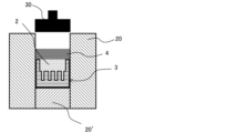
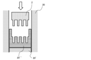
- the mold shown in FIG. FIG. 4 is a schematic diagram for explaining a state in which the molten metal of the matrix material 4 is poured after installation in the molds 20 and 20′.
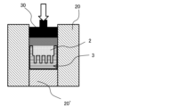
- FIG. 2B is a schematic diagram for explaining a state in which, after the molten metal of the matrix material 4 shown in FIG. 2A is poured, the pressurizer 30 is lowered to start pressurization.
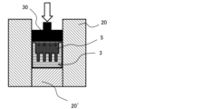
- FIG. 2B is a schematic diagram for explaining a casting process for increasing the casting pressure using the pressurizing indenter 30 shown in FIG. FIG.
- FIG. 2 is a schematic diagram for explaining one of the problems in the conventional method for producing a metal matrix composite material, wherein a molded body made of a reinforcing material 2 produced using another mold and taken out is separated from the molded body and the space. It is a schematic diagram showing that it is necessary to insert into a mold 20'' whose (concave portion) has a near-net shape. In order to carry out the casting process using the molten matrix material, the compact made of the reinforcing material 2 taken out from the mold is placed in a mold 20'' having a near-net-shaped space (recess) inside the compact. It is a schematic diagram for demonstrating the state inserted and accommodated.
- a feature of the method for producing a metal matrix composite material of the present invention is that the metal matrix composite material to be produced and a mold having a near-net shape space (concave part) used when producing a reinforcing material molded body are combined with the mold. It is used in a series of processes up to the time of casting, in which the reinforcing material compacts and fillers formed in step 1 are put in, and composited with the molten metal of the matrix material. It is that it is configured to be used for both molds.
- the method for producing a metal matrix composite material of the present invention is selected from the group consisting of a matrix material that is a pure metal or alloy such as aluminum or an aluminum alloy, and ceramic particles, graphite particles and metal particles different from the matrix material.
- a manufacturing method for easily obtaining a metal matrix composite material having a near-net shape with high dimensional accuracy and a high reinforcement volume ratio (Vf%) by compositing with at least one reinforcing material. is.
- the procedure is as follows: First, in a step of forming a reinforcing material molded body/filler for producing a near net shaped reinforcing material molded body or a reinforcing material filled body having pores inside using the reinforcing material, A material containing the reinforcing material is filled in a mold in which a space (recess) is formed to form a reinforcing material molded body/filled body in the mold. Next, the mold having the formed reinforcing material compact/filler therein is preheated in a preheating step.
- the mold containing the preheated reinforcing material molded body/filler is placed in the outer shell mold for composite material casting, and the reinforcing material molded body/filler contained in the mold is A casting step is performed in which the pores are impregnated and filled with the molten matrix material to form a composite of the matrix material and the reinforcing material.
- a casting step is performed in which the pores are impregnated and filled with the molten matrix material to form a composite of the matrix material and the reinforcing material.
- a series of steps of forming the reinforcing material compact/filler, preheating, and casting are performed to form a near-net-shaped space (recess) inside. It is characterized in that the same mold is also used for this purpose.
- the mold having recesses in a near-net shape which is also used in a series of steps of the manufacturing method of the present invention, is referred to as "a mold that is also used for reinforcing material molding and casting", or simply "a metal that is also used It is also called “mold” or “combined mold”.
- Reference numeral 1 or 3 in FIGS. 1 and 2 denotes a mold that is also used in a series of steps of molding, preheating, and casting of the reinforcing material compact/filler characterizing the present invention.
- the space (concave portion) of the mold 1 that is also used has a near-net shape that is formed into a desired shape substantially similar to the product manufactured using the composite material.
- 2 in FIGS. 1 and 2 indicates a material for forming a reinforcing compact/filler containing at least a reinforcing material selected from ceramic particles, graphite particles and metal particles. Further, 3 shown in FIGS.
- FIGS. 2A to 2C shows that the concave portion of the mold 1 also used is filled with the material 2 including the reinforcing material.
- the mold filled with the reinforcing material is referred to as a "reinforcing material-filled dual-use mold 3".
- the 10 in FIG. 1C indicates a heating furnace.
- the material 2 containing the reinforcing material placed (filled) in the mold 1 that is also used is baked and molded as necessary, or the reinforcing material molded body / filled body obtained in the molding process is preheated.
- the reinforcing material-filled dual-use mold 3 is placed in the heating furnace 10 and fired and preheated.
- the mold 1 is used when obtaining a reinforcing material filled body, or when obtaining a reinforcing material molded body by pressure molding or baking molding of the reinforcing material, and further, as shown in FIGS.
- the reinforcement-filled dual-use mold 3 is placed within the composite casting shell molds 20 and 20′, as shown in FIG. 1D, and then, as shown in FIGS. Casting is performed in this state.
- the manufacturing method of the present invention is characterized in that a series of all manufacturing steps are performed using the same mold in which a near-net-shaped space (concave portion) is formed.
- the outer shell mold for composite material casting shown in the schematic diagrams of FIG. 1D and FIGS. configured as follows. Then, at the time of casting, the reinforcing material-filled dual-use mold 3 is installed in the recess of the outer shell mold for casting the composite material, and casting is performed, for example, as shown in FIGS. and matrix material.
- a material 2 containing a reinforcing material is placed in a recess of a mold 1 that is also used in a series of steps to increase the volume of the reinforcing material.
- ratio (Vf %) for example, a reinforcing material molded body/filler having a reinforcing material volume fraction (Vf %) exceeding 40%.
- a reinforcing material such as ceramic particles is placed in the recess of the mold 1 that is also used, and the entire mold is vibrated with a vibrator, and the reinforcing material 2 is filled so that the desired high Vf% is obtained.
- a method of filling the concave portion of the mold 1 with the reinforcing material and then performing pressure molding by a conventionally known method to obtain the reinforcing material molded body is added to a reinforcing material such as ceramic particles to prepare a slurry designed so that the obtained reinforcing material molded body has a desired high Vf% and high strength.
- a method of filling the obtained slurry into the concave portion of the mold 1 to react and solidify the synthetic raw material of the resin binder to form a reinforcing material molded body in the concave portion can also be used.
- an inorganic binder is added to a reinforcing material such as ceramic particles to prepare a slurry designed so that the obtained reinforcing material molded body has the desired high Vf% and high strength, and the obtained slurry is used for strengthening.
- Obtaining a material compact is also a preferred embodiment. Specifically, after filling the concave portion of the mold 1 with the slurry containing the inorganic binder prepared above, the filled mold is placed in the heating furnace 10 and fired to form the inorganic binder. A method of obtaining a reinforcing material compact by bonding reinforcing materials can also be applied.
- the heating furnace for sintering molding and the heating furnace for preheating the reinforcing material compact obtained by sintering molding may be the same or different.
- the heating furnace what is put into the heating furnace is the "reinforcing material-filled dual-purpose mold 3" in which the dual-purpose mold 1 is filled with the reinforcing material, and the dual-purpose mold It is characterized in that it is put into the heating furnace 10 together.
- the reinforcing material-filled dual-purpose mold 3 is installed in the outer shell molds 20 and 20' for casting composite materials.
- the outer shell molds 20 and 20' may be preheated in order to avoid thermal shock. preferable.
- the pressurizing indenter is lowered, and casting is preferably performed by pressurizing to a casting pressure of about 80 MPa to 120 MPa, for example.
- the reinforcing material used in the manufacturing method of the present invention is not particularly limited, and any one conventionally used for metal matrix composite materials can be used.
- at least one fine particle selected from the group consisting of ceramic particles, graphite particles and metal particles may be used. More specifically, ceramic fine particles such as aluminum borate, silicon carbide, and alumina, fine particles of flake graphite, and metal particles such as Si particles and Al 3 Ni particles can be used.
- the matrix material is not particularly limited, and conventionally known materials can be appropriately used depending on the purpose.
- the matrix material includes pure metals or alloys such as aluminum or aluminum alloys, magnesium or magnesium alloys, copper or copper alloys, and the like. For example, by using aluminum or an aluminum alloy as the matrix material in the manufacturing method of the present invention, it is possible to easily provide a lightweight and functional member product, a near-net shape metal matrix composite material. is provided.
- Example 1 In this example, 1.0 kg of aluminum borate particles having an average particle size of 44 ⁇ m were used as the reinforcing material. Then, the aluminum borate particles of the reinforcing material are filled in a mold that is used for both molding and casting of the reinforcing material, and the dual-use mold is placed on a vibrator to apply vibration for 20 minutes to give the aluminum borate particles It was filled in the mold so that the filling rate of was over 40%.
- the mold used for molding the reinforcing material and casting used above had a near-net-shaped space (concave portion) therein, which was almost the same as the desired product made of the metal-based composite material.
- the mold used for reinforcing material molding and casting which has a reinforcing material compact obtained by filling aluminum borate particles as described above, is placed in a heating furnace as it is, and preheated to 700 ° C. in a nitrogen atmosphere. . Then, the preheated dual-use mold having the reinforcing material molded body inside was placed in the outer shell mold for composite material casting preheated to 200°C.
- the Al alloy molten metal (AC4C) quickly melted at 800 ° C. is poured into the outer shell mold for casting the composite material, the pressure indenter is lowered to increase the casting pressure to 100 MPa, and the pressure is increased. After holding for 10 minutes, a near net-shaped metal matrix composite material was molded. It was confirmed that the obtained metal matrix composite material had a shape almost close to the shape of the desired product and had a good near-net shape without chipping or cracking.
- Example 2 In this example, 2.0 kg of SiC particles having an average particle size of 20 ⁇ m were used as the reinforcing material.
- SiC particles of the reinforcing material were filled inside, the combined mold was placed in a small press, and pressure-molded at 10 MPa to obtain a reinforcing material compact with a filling rate of SiC particles of 50%.
- the reinforcing material molded body housed inside the dual-use mold is preheated to 800°C under a nitrogen atmosphere, and then the preheated reinforcing material is placed in the outer shell mold for composite material casting preheated to 250°C.
- the material molded body was installed together with the dual-use mold.
- the molten Al alloy (ADC12) melted at 800 ° C. is poured into the outer shell mold for casting the composite material, and the pressure indenter is lowered to increase the casting pressure to 80 MPa.
- the pressure was maintained for 15 minutes for compounding to form a near-net-shaped metal matrix composite material. It was confirmed that the obtained metal matrix composite material had a shape almost close to the shape of the desired product and had a good near-net shape without chipping or cracking.
- Example 3 In this example, 1.0 kg of aluminum borate particles having an average particle size of 44 ⁇ m were used as the reinforcing material. Then, to the aluminum borate particles of the reinforcing material, a total amount of 500 g of a resin monomer, a cross-linking agent, and a dispersing agent as raw materials of the binder was added, and 5 kg of water was added to prepare a slurry in which these raw materials were dispersed. .
- the resulting slurry After adding a polymerization initiator to the resulting slurry, the resulting slurry is filled in a mold that is also used for reinforcing material molding and casting, and left at room temperature to polymerize the resin monomer and the cross-linking agent to form a resin binder, aluminum borate.
- a reinforcing material compact having a particle filling rate of 60% was produced.
- the reinforcing material molded body housed inside the dual-use mold is heated to 700° C. in a nitrogen atmosphere to remove the resin binder, and then the outer shell mold for composite material casting preheated to 200° C. , the heated reinforcing material molded body was placed together with the dual-use mold. Then, immediately after installation, the molten Al alloy (AC4C) melted at 750 ° C. is poured into the outer shell mold for casting the composite material, and the pressure indenter is lowered to increase the casting pressure to 100 MPa. The pressure was maintained for 10 minutes to form a composite, thereby forming a near net-shaped metal matrix composite material. It was confirmed that the obtained metal matrix composite material had a shape almost close to the shape of the desired product and had a good near-net shape without chipping or cracking.
- AC4C molten Al alloy
- Example 4 In this example, 1.0 kg of scale-like graphite particles having an average particle size of 50 ⁇ m were used as the reinforcing material. Then, the scale-like graphite particles of the reinforcing material are filled in a mold that is used for both reinforcing material molding and casting, and the combined mold is placed in a small press machine, and the filling in the combined mold is heated at 20 MPa. A compacted reinforcing material having a filling rate of flaky graphite particles of 55% was produced by compression molding.
- the reinforcing material molded body housed in a mold that is also used for reinforcing material molding and casting is preheated to 700 ° C. in a nitrogen atmosphere, and in the outer shell mold for composite material casting preheated to 200 ° C., The preheated reinforcing material molded body was installed together with the dual-use mold.
- molten Al alloy (AC8A) melted at 800 ° C. is poured into the outer shell mold for casting composite materials, and the pressure indenter is lowered to increase the casting pressure to 100 MPa. The pressure was maintained for 10 minutes to form a composite, thereby forming a near net-shaped metal matrix composite material. It was confirmed that the obtained metal matrix composite material had a shape almost close to the shape of the desired product and had a good near-net shape without chipping or cracking.
Landscapes
- Engineering & Computer Science (AREA)
- Mechanical Engineering (AREA)
- Chemical & Material Sciences (AREA)
- Materials Engineering (AREA)
- Metallurgy (AREA)
- Organic Chemistry (AREA)
- Manufacture Of Alloys Or Alloy Compounds (AREA)
Abstract
Description
[1]アルミニウム又はアルミニウム合金等の純金属あるいは合金であるマトリックス材と、該マトリックス材とは異なるセラミックス粒子、黒鉛粒子及び金属粒子からなる群から選ばれる少なくともいずれかの材料からなる強化材とを複合化させて、寸法精度の高いニアネット形状で、且つ、高い強化材容積率(Vf%)を有する金属基複合材料を得るための金属基複合材料の製造方法であって、
前記強化材を用いて内部に多孔を有するニアネット形状の強化材成形体又は強化材充填体を作製する強化材成形体・充填体の成形工程で、内部にニアネット形状の空間(凹部)が形成される金型内に前記強化材を含む材料を充填して、該金型内に強化材成形体・充填体を形成し、形成した強化材成形体・充填体を有してなる金型を予熱工程で予熱し、予熱された強化材成形体・充填体が入った状態の金型を複合材鋳造用外殻金型内に設置して、前記金型内に入っている強化材成形体・充填体の前記多孔に溶融したマトリックス材を含浸・充填して、前記マトリックス材と前記強化材とを複合化する鋳造工程を行う、前記強化材成形体・充填体の成形工程、前記予熱工程及び前記鋳造工程の一連の工程において同一の金型を兼用することを特徴とする金属基複合材料の製造方法。
[2]前記強化材容積率(Vf%)が、40%を超える上記[1]に記載の金属基複合材料の製造方法。
[3]前記強化材成形体・充填体の成形工程で、内部にニアネット形状の空間(凹部)が形成される前記金型内に前記強化材を少なくとも含む材料を充填して、該材料が充填された状態の前記金型を兼用して、該兼用する金型内に充填された材料を加圧成形、或いは、該兼用する金型を加熱炉に入れて該金型内に充填された材料の焼成成形を行って強化材成形体を得る[1]又は[2]に記載の金属基複合材料の製造方法。
[4]前記鋳造工程で、加圧圧子を用い、鋳造圧力80MPa~120MPaに加圧して鋳造する上記[1]~[3]のいずれかに記載の金属基複合材料の製造方法。
[5]前記強化材が、ホウ酸アルミニウム粒子、炭化ケイ素粒子、アルミナ粒子、SiC粒子、黒鉛粒子、Si粒子及びAl3Ni粒子からなる群から選ばれる少なくともいずれかである上記[1]~[4]のいずれかに記載の金属基複合材料の製造方法。
本例では、強化材として平均粒径44μmのホウ酸アルミニウム粒子1.0kgを用いた。そして、強化材のホウ酸アルミニウム粒子を強化材成形及び鋳造に兼用する金型内に充填して、該兼用金型を振動機の上に設置して振動を20分間与えて、ホウ酸アルミニウム粒子の充填率が40%超になるように金型内に充填した。上記で使用した強化材成形及び鋳造に兼用する金型には、内部に所望する金属基複合材からなる製品とほぼ同じ、ニアネット形状の空間(凹部)を有するものを用いた。
本例では、強化材として平均粒径20μmのSiC粒子2.0kgを用いた。実施例1で用いたと同様の、内部に所望する金属基複合材からなる製品とほぼ同じニアネット形状の空間(凹部)を有する強化材成形及び鋳造に兼用する金型を用い、該兼用金型内に強化材のSiC粒子を充填して兼用金型ごと小型プレス機に設置し、10MPaで加圧成型してSiC粒子の充填率を50%にした強化材成形体を得た。
本例では、強化材として平均粒径44μmのホウ酸アルミニウム粒子1.0kgを用いた。そして、強化材のホウ酸アルミニウム粒子に、バインダーの原料として樹脂モノマーと架橋剤、分散剤を総量で500gとなる量加え、さらに水を5kg加えてこれらの原料が分散してなるスラリーを作製した。得られたスラリーに重合開始剤を添加した後、強化材成形及び鋳造に兼用する金型内に充填して、常温で放置して樹脂モノマー及び架橋剤を重合させて樹脂バインダーとし、ホウ酸アルミニウム粒子の充填率を60%にした強化材成形体を作製した。
本例では、強化材として平均粒径50μmの鱗片状黒鉛粒子1.0kgを用いた。そして、強化材の鱗片状黒鉛粒子を強化材成形及び鋳造に兼用する金型内に充填して、該兼用金型ごと小型プレス機に設置して、兼用金型内の充填物を20MPaで加圧成型し、鱗片状黒鉛粒子の充填率を55%にした強化材成形体を作製した。
2:強化材
3:強化材充填済兼用金型
4:マトリックス材
10:加熱炉
20、20’、20’’:複合材鋳造用外殻金型
30:加圧圧子
Claims (5)
- アルミニウム又はアルミニウム合金等の純金属あるいは合金であるマトリックス材と、該マトリックス材とは異なるセラミックス粒子、黒鉛粒子及び金属粒子からなる群から選ばれる少なくともいずれかの材料からなる強化材とを複合化させて、寸法精度の高いニアネット形状で、且つ、高い強化材容積率(Vf%)を有する金属基複合材料を得るための金属基複合材料の製造方法であって、
前記強化材を用いて内部に多孔を有するニアネット形状の強化材成形体又は強化材充填体を作製する強化材成形体・充填体の成形工程で、内部にニアネット形状の空間(凹部)が形成される金型内に前記強化材を含む材料を充填して、該金型内に強化材成形体・充填体を形成し、形成した強化材成形体・充填体を有してなる金型を予熱工程で予熱し、予熱された強化材成形体・充填体が入った状態の金型を複合材鋳造用外殻金型内に設置して、前記金型内に入っている強化材成形体・充填体の前記多孔に溶融したマトリックス材を含浸・充填して、前記マトリックス材と前記強化材とを複合化する鋳造工程を行う、前記強化材成形体・充填体の成形工程、前記予熱工程及び前記鋳造工程の一連の工程において同一の金型を兼用することを特徴とする金属基複合材料の製造方法。 - 前記強化材容積率(Vf%)が、40%を超える請求項1に記載の金属基複合材料の製造方法。
- 前記強化材成形体・充填体の成形工程で、内部にニアネット形状の空間(凹部)が形成される前記金型内に前記強化材を少なくとも含む材料を充填して、該材料が充填された状態の前記金型を兼用して、該兼用する金型内に充填された材料を加圧成形、或いは、該兼用する金型を加熱炉に入れて該金型内に充填された材料の焼成成形を行って強化材成形体を得る請求項1又は2に記載の金属基複合材料の製造方法。
- 前記鋳造工程で、加圧圧子を用い、鋳造圧力80MPa~120MPaに加圧して鋳造する請求項1~3のいずれか1項に記載の金属基複合材料の製造方法。
- 前記強化材が、ホウ酸アルミニウム粒子、炭化ケイ素粒子、アルミナ粒子、SiC粒子、黒鉛粒子、Si粒子及びAl3Ni粒子からなる群から選ばれる少なくともいずれかである請求項1~4のいずれか1項に記載の金属基複合材料の製造方法。
Priority Applications (3)
| Application Number | Priority Date | Filing Date | Title |
|---|---|---|---|
| US18/557,983 US12325065B2 (en) | 2022-01-14 | 2022-12-23 | Method for manufacturing metal matrix composite material |
| CN202280039124.3A CN117412826A (zh) | 2022-01-14 | 2022-12-23 | 金属基复合材料的制造方法 |
| EP22920618.0A EP4464436A4 (en) | 2022-01-14 | 2022-12-23 | METHOD FOR MANUFACTURING A METAL MATRIX COMPOSITE MATERIAL |
Applications Claiming Priority (2)
| Application Number | Priority Date | Filing Date | Title |
|---|---|---|---|
| JP2022004377A JP7197946B1 (ja) | 2022-01-14 | 2022-01-14 | 金属基複合材料の製造方法 |
| JP2022-004377 | 2022-01-14 |
Publications (1)
| Publication Number | Publication Date |
|---|---|
| WO2023136101A1 true WO2023136101A1 (ja) | 2023-07-20 |
Family
ID=84688913
Family Applications (1)
| Application Number | Title | Priority Date | Filing Date |
|---|---|---|---|
| PCT/JP2022/047659 Ceased WO2023136101A1 (ja) | 2022-01-14 | 2022-12-23 | 金属基複合材料の製造方法 |
Country Status (5)
| Country | Link |
|---|---|
| US (1) | US12325065B2 (ja) |
| EP (1) | EP4464436A4 (ja) |
| JP (1) | JP7197946B1 (ja) |
| CN (1) | CN117412826A (ja) |
| WO (1) | WO2023136101A1 (ja) |
Families Citing this family (1)
| Publication number | Priority date | Publication date | Assignee | Title |
|---|---|---|---|---|
| CN119456946A (zh) * | 2024-11-08 | 2025-02-18 | 哈尔滨工业大学 | 一种内置芯模近净成型高精度高致密度金属基复合材料复杂构件的方法 |
Citations (9)
| Publication number | Priority date | Publication date | Assignee | Title |
|---|---|---|---|---|
| JPS6224853A (ja) * | 1985-07-25 | 1987-02-02 | Toyota Motor Corp | 断熱部を有する鋳物部材の製造方法 |
| JPH08501500A (ja) * | 1992-09-17 | 1996-02-20 | エー. リットランド,マーカス | セラミック−金属複合材の製造方法 |
| JPH08267217A (ja) * | 1995-03-30 | 1996-10-15 | Toyota Central Res & Dev Lab Inc | 多孔質強化焼結体およびその製造方法、この多孔質強化焼結体を用いた複合材料およびその製造方法 |
| JPH10174222A (ja) | 1996-12-09 | 1998-06-26 | Kawamura Electric Inc | 分電盤 |
| JPH1150173A (ja) * | 1997-08-05 | 1999-02-23 | Chichibu Onoda Cement Corp | 金属−セラミックス複合材料の製造方法 |
| JP2000336438A (ja) * | 1999-03-25 | 2000-12-05 | Kubota Corp | 金属−セラミックス複合材料およびその製造方法 |
| JP2012184493A (ja) * | 2011-03-08 | 2012-09-27 | Taiheiyo Cement Corp | 金属−セラミックス複合材料及びその製造方法 |
| JP2013087307A (ja) * | 2011-10-14 | 2013-05-13 | Hitachi Metals Ltd | 金属−セラミックス複合材の製造方法及び金属−セラミックス複合材 |
| JP2015531688A (ja) * | 2013-06-26 | 2015-11-05 | ティー アンド マテリアルズ カンパニー,リミテッド | 加圧含浸型金属基材複合材料の製造方法 |
Family Cites Families (21)
| Publication number | Priority date | Publication date | Assignee | Title |
|---|---|---|---|---|
| JPS60115361A (ja) * | 1983-11-25 | 1985-06-21 | Toyota Motor Corp | 複合材料の製造方法 |
| US4712600A (en) | 1985-07-12 | 1987-12-15 | Toyota Jidosha Kabushiki Kaisha | Production of pistons having a cavity |
| JPH0636977B2 (ja) * | 1986-04-09 | 1994-05-18 | 東海カ−ボン株式会社 | 繊維強化金属複合材の製造方法 |
| US5163498A (en) * | 1989-11-07 | 1992-11-17 | Lanxide Technology Company, Lp | Method of forming metal matrix composite bodies having complex shapes by a self-generated vacuum process, and products produced therefrom |
| JPH05169234A (ja) * | 1991-12-19 | 1993-07-09 | Toyota Motor Corp | 短繊維強化金属複合材料の製造方法及び装置 |
| US5676907A (en) * | 1992-09-17 | 1997-10-14 | Coors Ceramics Company | Method for making near net shape ceramic-metal composites |
| US5503122A (en) | 1992-09-17 | 1996-04-02 | Golden Technologies Company | Engine components including ceramic-metal composites |
| DE4343945C1 (de) * | 1993-12-22 | 1995-09-14 | Austria Metall | Verfahren zum Herstellen von Metall-Matrix-Verbundwerkstoffen |
| JP3133262B2 (ja) | 1996-12-24 | 2001-02-05 | 本田技研工業株式会社 | 複合材の成形方法 |
| JP2002069548A (ja) * | 2000-09-04 | 2002-03-08 | Toyota Industries Corp | 複合材料の製造方法 |
| FR2871153B1 (fr) | 2004-06-02 | 2006-08-11 | Otv Sa | Procede de traitement d'eaux a l'aide d'un reacteur biologique, dans lequel la vitesse d'air injecte dans le reacteur est regulee, et dispositif correspondant |
| JP5032812B2 (ja) * | 2006-09-15 | 2012-09-26 | 中央精機株式会社 | 金属複合材および金属複合材の製造方法 |
| JP4710866B2 (ja) | 2007-04-18 | 2011-06-29 | トヨタ自動車株式会社 | 内燃機関の排気浄化装置 |
| CN100485067C (zh) * | 2007-07-31 | 2009-05-06 | 哈尔滨工业大学 | 采用TiB2颗粒的高强塑性铝基复合材料的制备方法 |
| JP2010180434A (ja) | 2009-02-03 | 2010-08-19 | Tokyo Electron Ltd | 成膜方法及びプラズマ成膜装置 |
| JP5328567B2 (ja) | 2009-08-27 | 2013-10-30 | 日新電機株式会社 | 引出形電気機器の断路機構 |
| MX370222B (es) * | 2012-01-31 | 2019-12-05 | Esco Group Llc | Material resistente al desgaste, y sistema y metodo para crear un material resistente al desgaste. |
| CN103056338B (zh) * | 2012-12-14 | 2015-06-17 | 江苏时代华宜电子科技有限公司 | 大功率模块用铝碳化硅基板成形方法 |
| JP6681079B2 (ja) * | 2017-11-30 | 2020-04-15 | アドバンスコンポジット株式会社 | アルミニウム合金基複合材料の製造方法及びアルミニウム合金基複合材料 |
| CN113278843B (zh) * | 2021-05-25 | 2021-12-24 | 江南大学 | 一种热等静压制备金属基陶瓷复合材料的制造工艺 |
| CN113275535B (zh) * | 2021-05-25 | 2022-03-29 | 江南大学 | 一种提高金属基复合材料性能的成型压铸工艺 |
-
2022
- 2022-01-14 JP JP2022004377A patent/JP7197946B1/ja active Active
- 2022-12-23 CN CN202280039124.3A patent/CN117412826A/zh active Pending
- 2022-12-23 WO PCT/JP2022/047659 patent/WO2023136101A1/ja not_active Ceased
- 2022-12-23 EP EP22920618.0A patent/EP4464436A4/en active Pending
- 2022-12-23 US US18/557,983 patent/US12325065B2/en active Active
Patent Citations (9)
| Publication number | Priority date | Publication date | Assignee | Title |
|---|---|---|---|---|
| JPS6224853A (ja) * | 1985-07-25 | 1987-02-02 | Toyota Motor Corp | 断熱部を有する鋳物部材の製造方法 |
| JPH08501500A (ja) * | 1992-09-17 | 1996-02-20 | エー. リットランド,マーカス | セラミック−金属複合材の製造方法 |
| JPH08267217A (ja) * | 1995-03-30 | 1996-10-15 | Toyota Central Res & Dev Lab Inc | 多孔質強化焼結体およびその製造方法、この多孔質強化焼結体を用いた複合材料およびその製造方法 |
| JPH10174222A (ja) | 1996-12-09 | 1998-06-26 | Kawamura Electric Inc | 分電盤 |
| JPH1150173A (ja) * | 1997-08-05 | 1999-02-23 | Chichibu Onoda Cement Corp | 金属−セラミックス複合材料の製造方法 |
| JP2000336438A (ja) * | 1999-03-25 | 2000-12-05 | Kubota Corp | 金属−セラミックス複合材料およびその製造方法 |
| JP2012184493A (ja) * | 2011-03-08 | 2012-09-27 | Taiheiyo Cement Corp | 金属−セラミックス複合材料及びその製造方法 |
| JP2013087307A (ja) * | 2011-10-14 | 2013-05-13 | Hitachi Metals Ltd | 金属−セラミックス複合材の製造方法及び金属−セラミックス複合材 |
| JP2015531688A (ja) * | 2013-06-26 | 2015-11-05 | ティー アンド マテリアルズ カンパニー,リミテッド | 加圧含浸型金属基材複合材料の製造方法 |
Non-Patent Citations (1)
| Title |
|---|
| See also references of EP4464436A4 |
Also Published As
| Publication number | Publication date |
|---|---|
| JP2023103704A (ja) | 2023-07-27 |
| JP7197946B1 (ja) | 2022-12-28 |
| EP4464436A1 (en) | 2024-11-20 |
| EP4464436A4 (en) | 2026-01-14 |
| US20240216987A1 (en) | 2024-07-04 |
| US12325065B2 (en) | 2025-06-10 |
| CN117412826A (zh) | 2024-01-16 |
Similar Documents
| Publication | Publication Date | Title |
|---|---|---|
| CN1208149C (zh) | 用于高压铸造的溃散芯、制造该芯的方法以及抽取该芯的方法 | |
| US5937932A (en) | Casting tooling | |
| KR100545802B1 (ko) | 실린더블록 및 금속기(金屬基)복합재용 프리폼 | |
| Yang et al. | Casting particulate and fibrous metal-matrix composites by vacuum infiltration of a liquid metal under an inert gas pressure | |
| JP4429505B2 (ja) | 低体積分率金属基プリフォームの製造方法 | |
| WO2023136101A1 (ja) | 金属基複合材料の製造方法 | |
| JP2000225457A (ja) | セラミックス強化金属基複合材料およびその製造方法 | |
| CN115917022A (zh) | 金属基复合材料的制造方法及预制件的制作方法 | |
| CN114042910A (zh) | 一种陶瓷增强金属基复合材料的制备方法 | |
| US4573519A (en) | Method for forming metal base composite | |
| JP5117085B2 (ja) | 金属−セラミックス複合材料及びその製造方法 | |
| EP4144461A1 (en) | Method for producing high metal powder content aluminum composite body, method for preparing preform, and high metal powder content aluminum composite body | |
| KR100653161B1 (ko) | 알루미늄기 복합재를 이용한 반고상가압주조방법 | |
| JP2001507281A (ja) | 機械加工可能な金属マトリックス複合体及び液体金属浸透方法 | |
| JP4524591B2 (ja) | 複合材料およびその製造方法 | |
| JP7382105B1 (ja) | 高強度金属基複合体及び高強度金属基複合体の製造方法 | |
| JP4276304B2 (ja) | 金属−セラミックス複合材料の製造方法 | |
| JP3232029B2 (ja) | シリンダブロック | |
| KR102541042B1 (ko) | 소결재를 사용한 고압 주조방법 및 고압 주조품 | |
| CA2770464A1 (en) | A process for producing a metal-matrix composite of significant .delta.cte between the hard base-metal and the soft matrix | |
| CN121044906A (zh) | 一种光固化多孔陶瓷浸渗铝合金的铝基复合材料的制备方法 | |
| RU2625377C1 (ru) | Способ изготовления композиционного материала для изделий электронной техники СВЧ | |
| JPH0435542B2 (ja) | ||
| JP2003253308A (ja) | アルミニウム基複合材料の製造方法 | |
| JP2002194458A (ja) | ベンチ型ロータ |
Legal Events
| Date | Code | Title | Description |
|---|---|---|---|
| 121 | Ep: the epo has been informed by wipo that ep was designated in this application |
Ref document number: 22920618 Country of ref document: EP Kind code of ref document: A1 |
|
| WWE | Wipo information: entry into national phase |
Ref document number: 18557983 Country of ref document: US |
|
| WWE | Wipo information: entry into national phase |
Ref document number: 202280039124.3 Country of ref document: CN |
|
| WWE | Wipo information: entry into national phase |
Ref document number: 2022920618 Country of ref document: EP |
|
| NENP | Non-entry into the national phase |
Ref country code: DE |
|
| ENP | Entry into the national phase |
Ref document number: 2022920618 Country of ref document: EP Effective date: 20240814 |
|
| WWG | Wipo information: grant in national office |
Ref document number: 18557983 Country of ref document: US |