WO2023140220A1 - 車両用ガラスモジュール - Google Patents
車両用ガラスモジュール Download PDFInfo
- Publication number
- WO2023140220A1 WO2023140220A1 PCT/JP2023/000997 JP2023000997W WO2023140220A1 WO 2023140220 A1 WO2023140220 A1 WO 2023140220A1 JP 2023000997 W JP2023000997 W JP 2023000997W WO 2023140220 A1 WO2023140220 A1 WO 2023140220A1
- Authority
- WO
- WIPO (PCT)
- Prior art keywords
- bracket
- adhesive member
- hole
- support portion
- vehicle glass
- Prior art date
- Legal status (The legal status is an assumption and is not a legal conclusion. Google has not performed a legal analysis and makes no representation as to the accuracy of the status listed.)
- Ceased
Links
Images






Classifications
-
- B—PERFORMING OPERATIONS; TRANSPORTING
- B60—VEHICLES IN GENERAL
- B60R—VEHICLES, VEHICLE FITTINGS, OR VEHICLE PARTS, NOT OTHERWISE PROVIDED FOR
- B60R11/00—Arrangements for holding or mounting articles, not otherwise provided for
- B60R11/04—Mounting of cameras operative during drive; Arrangement of controls thereof relative to the vehicle
-
- B—PERFORMING OPERATIONS; TRANSPORTING
- B32—LAYERED PRODUCTS
- B32B—LAYERED PRODUCTS, i.e. PRODUCTS BUILT-UP OF STRATA OF FLAT OR NON-FLAT, e.g. CELLULAR OR HONEYCOMB, FORM
- B32B17/00—Layered products essentially comprising sheet glass, or glass, slag, or like fibres
- B32B17/06—Layered products essentially comprising sheet glass, or glass, slag, or like fibres comprising glass as the main or only constituent of a layer, next to another layer of a specific material
- B32B17/10—Layered products essentially comprising sheet glass, or glass, slag, or like fibres comprising glass as the main or only constituent of a layer, next to another layer of a specific material of synthetic resin
- B32B17/10005—Layered products essentially comprising sheet glass, or glass, slag, or like fibres comprising glass as the main or only constituent of a layer, next to another layer of a specific material of synthetic resin laminated safety glass or glazing
- B32B17/10165—Functional features of the laminated safety glass or glazing
-
- B—PERFORMING OPERATIONS; TRANSPORTING
- B32—LAYERED PRODUCTS
- B32B—LAYERED PRODUCTS, i.e. PRODUCTS BUILT-UP OF STRATA OF FLAT OR NON-FLAT, e.g. CELLULAR OR HONEYCOMB, FORM
- B32B17/00—Layered products essentially comprising sheet glass, or glass, slag, or like fibres
- B32B17/06—Layered products essentially comprising sheet glass, or glass, slag, or like fibres comprising glass as the main or only constituent of a layer, next to another layer of a specific material
- B32B17/10—Layered products essentially comprising sheet glass, or glass, slag, or like fibres comprising glass as the main or only constituent of a layer, next to another layer of a specific material of synthetic resin
- B32B17/10005—Layered products essentially comprising sheet glass, or glass, slag, or like fibres comprising glass as the main or only constituent of a layer, next to another layer of a specific material of synthetic resin laminated safety glass or glazing
- B32B17/10009—Layered products essentially comprising sheet glass, or glass, slag, or like fibres comprising glass as the main or only constituent of a layer, next to another layer of a specific material of synthetic resin laminated safety glass or glazing characterized by the number, the constitution or treatment of glass sheets
- B32B17/10036—Layered products essentially comprising sheet glass, or glass, slag, or like fibres comprising glass as the main or only constituent of a layer, next to another layer of a specific material of synthetic resin laminated safety glass or glazing characterized by the number, the constitution or treatment of glass sheets comprising two outer glass sheets
-
- B—PERFORMING OPERATIONS; TRANSPORTING
- B32—LAYERED PRODUCTS
- B32B—LAYERED PRODUCTS, i.e. PRODUCTS BUILT-UP OF STRATA OF FLAT OR NON-FLAT, e.g. CELLULAR OR HONEYCOMB, FORM
- B32B17/00—Layered products essentially comprising sheet glass, or glass, slag, or like fibres
- B32B17/06—Layered products essentially comprising sheet glass, or glass, slag, or like fibres comprising glass as the main or only constituent of a layer, next to another layer of a specific material
- B32B17/10—Layered products essentially comprising sheet glass, or glass, slag, or like fibres comprising glass as the main or only constituent of a layer, next to another layer of a specific material of synthetic resin
- B32B17/10005—Layered products essentially comprising sheet glass, or glass, slag, or like fibres comprising glass as the main or only constituent of a layer, next to another layer of a specific material of synthetic resin laminated safety glass or glazing
- B32B17/1055—Layered products essentially comprising sheet glass, or glass, slag, or like fibres comprising glass as the main or only constituent of a layer, next to another layer of a specific material of synthetic resin laminated safety glass or glazing characterized by the resin layer, i.e. interlayer
- B32B17/10761—Layered products essentially comprising sheet glass, or glass, slag, or like fibres comprising glass as the main or only constituent of a layer, next to another layer of a specific material of synthetic resin laminated safety glass or glazing characterized by the resin layer, i.e. interlayer containing vinyl acetal
-
- B—PERFORMING OPERATIONS; TRANSPORTING
- B32—LAYERED PRODUCTS
- B32B—LAYERED PRODUCTS, i.e. PRODUCTS BUILT-UP OF STRATA OF FLAT OR NON-FLAT, e.g. CELLULAR OR HONEYCOMB, FORM
- B32B17/00—Layered products essentially comprising sheet glass, or glass, slag, or like fibres
- B32B17/06—Layered products essentially comprising sheet glass, or glass, slag, or like fibres comprising glass as the main or only constituent of a layer, next to another layer of a specific material
- B32B17/10—Layered products essentially comprising sheet glass, or glass, slag, or like fibres comprising glass as the main or only constituent of a layer, next to another layer of a specific material of synthetic resin
- B32B17/10005—Layered products essentially comprising sheet glass, or glass, slag, or like fibres comprising glass as the main or only constituent of a layer, next to another layer of a specific material of synthetic resin laminated safety glass or glazing
- B32B17/1055—Layered products essentially comprising sheet glass, or glass, slag, or like fibres comprising glass as the main or only constituent of a layer, next to another layer of a specific material of synthetic resin laminated safety glass or glazing characterized by the resin layer, i.e. interlayer
- B32B17/10788—Layered products essentially comprising sheet glass, or glass, slag, or like fibres comprising glass as the main or only constituent of a layer, next to another layer of a specific material of synthetic resin laminated safety glass or glazing characterized by the resin layer, i.e. interlayer containing ethylene vinylacetate
-
- B—PERFORMING OPERATIONS; TRANSPORTING
- B32—LAYERED PRODUCTS
- B32B—LAYERED PRODUCTS, i.e. PRODUCTS BUILT-UP OF STRATA OF FLAT OR NON-FLAT, e.g. CELLULAR OR HONEYCOMB, FORM
- B32B3/00—Layered products comprising a layer with external or internal discontinuities or unevennesses, or a layer of non-planar shape; Layered products comprising a layer having particular features of form
- B32B3/26—Layered products comprising a layer with external or internal discontinuities or unevennesses, or a layer of non-planar shape; Layered products comprising a layer having particular features of form characterised by a particular shape of the outline of the cross-section of a continuous layer; characterised by a layer with cavities or internal voids ; characterised by an apertured layer
- B32B3/266—Layered products comprising a layer with external or internal discontinuities or unevennesses, or a layer of non-planar shape; Layered products comprising a layer having particular features of form characterised by a particular shape of the outline of the cross-section of a continuous layer; characterised by a layer with cavities or internal voids ; characterised by an apertured layer characterised by an apertured layer, the apertures going through the whole thickness of the layer, e.g. expanded metal, perforated layer, slit layer regular cells B32B3/12
-
- B—PERFORMING OPERATIONS; TRANSPORTING
- B60—VEHICLES IN GENERAL
- B60R—VEHICLES, VEHICLE FITTINGS, OR VEHICLE PARTS, NOT OTHERWISE PROVIDED FOR
- B60R11/00—Arrangements for holding or mounting articles, not otherwise provided for
- B60R2011/0001—Arrangements for holding or mounting articles, not otherwise provided for characterised by position
- B60R2011/0003—Arrangements for holding or mounting articles, not otherwise provided for characterised by position inside the vehicle
- B60R2011/0026—Windows, e.g. windscreen
Definitions
- the present invention relates to a vehicle glass module for supporting an information acquisition device installed in a vehicle.
- the vehicle glass module described in Patent Document 1 includes a glass base material composed of laminated glass, and a bracket having a hook-shaped engaging portion with one end face adhered to the inner surface of the glass base material with an adhesive and the other end face inserted into a part of the intermediate film of the glass base material.
- An information acquisition device (an information device in the document) is fixed to this bracket, and the engaging portion prevents the bracket from coming off.
- Patent Document 1 Although the vehicle glass module described in Patent Document 1 prevents falling off by providing an engaging portion on the bracket, the manufacturing efficiency is poor because it is necessary to process the glass base material in order to engage the engaging portion. Moreover, since the information acquisition device is heavy, it is necessary to improve the adhesive strength of one end surface of the bracket that is adhered to the inner surface of the glass substrate with an adhesive.
- a vehicle glass module according to the present invention is characterized in that it is a vehicle glass module for supporting an information acquisition device installed in a vehicle, comprising a glass base material having an outer surface and an inner surface, a bracket having a first surface bonded to the inner surface of the glass base material with an adhesive member, and a second surface opposite to the glass base material, and the bracket has a supporting portion that contacts the second surface and supports its own weight while connected to the adhesive member.
- the vehicle glass module of this configuration has an adhesive member that adheres the first surface of the bracket on the side of the glass base material to the inner surface of the glass base material, and a supporting portion that contacts the second surface of the bracket on the side opposite to the glass base material while connected to the adhesive member.
- the bracket can be adhered to the glass substrate by the adhesive member, and the bracket can be held by the support portion connected to the adhesive member.
- the bonding member repeatedly compresses and expands.
- the bonding strength between the bracket and the bonding member is likely to decrease compared to the bonding strength between the glass base material and the bonding member, and the bracket that supports the weight of the information acquisition device, which is a heavy object, may fall.
- the bracket can be properly supported on the glass base material with a simple configuration such as providing a support portion that abuts on the second surface of the bracket.
- the adhesive member is an adhesive
- the support portion is made of the same material that is continuous with the adhesive.
- the adhesive member is an adhesive
- the support portion connected to the adhesive member is formed of the same material that is continuous with the adhesive, so that the support portion can be easily configured.
- both the adhesive member and the supporting portion are made of adhesive, the supporting portion is firmly connected to the adhesive member. As a result, the bracket can be more properly supported on the glass substrate.
- bracket is formed with a through hole that communicates between the first surface and the second surface, the adhesive member and the support portion are connected through the through hole, the adhesive member is arranged in a region of the first surface adjacent to the through hole and the through hole, and the support portion is arranged in a region of the second surface adjacent to the through hole and the through hole.
- the adhesive member and the support portion By connecting the adhesive member and the support portion through the through hole formed in the bracket as in this configuration, the adhesive member and the support portion can be easily connected. Moreover, since the area of the first surface and the area of the second surface of the bracket are connected via the through hole, the supporting force of the support portion can be increased.
- bracket is formed with a plurality of the through holes, and the support portion connects the plurality of the through holes on the second surface.
- connection strength between the adhesive member and the support portion can be increased.
- the bracket can be more properly supported on the glass substrate.
- the through hole has a tapered shape that expands in diameter from the first surface toward the second surface.
- the through-hole formed in the bracket has a tapered shape that expands in diameter from the first surface toward the second surface, the diameter of the through-hole increases as it approaches the second surface of the bracket.
- the support portion that abuts on the second surface of the bracket is guided by the tapered portion of the through hole to come close to the adhesive member.
- the adhesive member is an adhesive
- the adhesive filled in the through-hole can be brought closer to the second surface side of the bracket simply by pressing the bracket against the glass substrate with the adhesive interposed between the first surface of the bracket and the glass substrate. Thereby, the supporting portion can be easily connected to the adhesive member.
- Another characteristic configuration is that the second surface has a projecting portion that projects away from the first surface, and the support portion is in contact with the projecting portion.
- the supporting portion when the second surface of the bracket has a projecting portion projecting in a direction away from the first surface, and the supporting portion is in contact with the projecting portion, the supporting portion can be connected to the adhesive member via the projecting portion of the bracket.
- the projecting portion is a portion projecting from the second surface of the bracket
- the information acquisition device may be attached to the projecting portion. In that case, since the load of the information acquisition device tends to be concentrated on the projecting portion, the bracket can be reliably prevented from falling by bringing the supporting portion into contact with the projecting portion. As a result, the holding force of the bracket by the adhesive member and the support portion can be increased.
- Another characteristic configuration is that the support portion is arranged continuously to a region adjacent to the protrusion portion on the second surface.
- bracket is formed with a through hole that communicates the first surface and the second surface, and the protruding portion protrudes from the outer edge of the through hole.
- the bracket is formed with a through hole that communicates the first surface and the second surface, and the protruding portion protrudes from the outer edge of the through hole, the bonding member and the support portion can be connected inside the through hole and the protruding portion that is continuous with the through hole. Thereby, the adhesive member and the supporting portion can be reliably connected.
- Another characteristic configuration is that the protrusion is formed on the outer edge of the bracket.
- the load of the information acquisition device or the like that the bracket receives tends to increase toward the outer edge of the bracket. Therefore, in this configuration, the protrusion is formed on the outer edge of the bracket.
- Another characteristic configuration is that the projecting portion is formed on the outer edge of the bracket, a communication hole is formed in the projecting portion along a direction intersecting the projecting direction, and the support portion is composed of the adhesive member that enters the communication hole.
- the supporting portion is composed of the adhesive member that enters the communicating hole formed in the protrusion provided on the outer edge of the bracket, so that the supporting force of the bracket can be increased by the adhesive member present in the communicating hole.
- Another characteristic configuration is that the difference in coefficient of linear expansion between the adhesive member and the support portion is smaller than the difference in coefficient of linear expansion between the adhesive member and the first surface.
- the shear stress generated between the adhesive member and the support portion becomes smaller than the shear stress generated between the adhesive member and the first surface of the bracket when affected by temperature changes such as solar radiation.
- the supporting portion connected to the bonding member can prevent the bracket from coming off and support the bracket. As a result, the bracket can be more properly supported on the glass substrate.
- the support portion is composed of a plurality of members made of different materials.
- the support section is composed of a plurality of members made of different materials, it is possible to appropriately select the member according to the arrangement location, for example, in the support section, the connection part with the adhesive member and the part that contacts the second surface of the bracket are made different members.
- the support portion is composed of a separate member made of a material different from that of the adhesive member.
- the support section is composed of a material different from that of the adhesive member, the range of selection of members for the support section is widened, and it is possible to appropriately select the member of the support section according to the weight of the device to be attached to the bracket.
- FIG. 4 is a cross-sectional view showing a state in which the vehicle glass module is mounted;
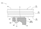
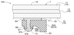
- FIG. 1 A cross-sectional view of a main part of a vehicle glass module according to a first embodiment.
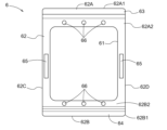
- FIG. 4 is a view of the bracket according to the first embodiment as seen from the inside of the vehicle;
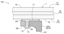
- FIG. [FIG. 2] is a cross-sectional view of a main part of Modified Example 1 of the vehicle glass module of the first embodiment;
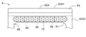
- Fig. 10 is a plan view of a main part of Modified Example 2 of the vehicle glass module of the first embodiment;
- FIG. 2] is a cross-sectional view of a main part of Modified Example 2 of the vehicle glass module of the first embodiment.
- FIG. 11 is a cross-sectional view of a main part of Modified Example 3 of the vehicle glass module of the first embodiment;
- FIG. 2 is a cross-sectional view of a main part of a vehicle glass module according to a second embodiment.
- FIG. 11 is a cross-sectional view of a main part of a modification of the vehicle glass module of the second embodiment.
- FIG. 2 is a cross-sectional view of a main part of a vehicle glass module according to a third embodiment.
- FIG. 11] is a cross-sectional view of a main part of a modification of the third embodiment;
- FIG. 11] is a cross-sectional view of a main part of a vehicle glass module according to a fourth embodiment; [FIG.
- FIG. 11] is a cross-sectional view of a main part of Modification 1 of the vehicle glass module of the fourth embodiment;
- FIG. 11] is a cross-sectional view of a main part of Modified Example 2 of the vehicle glass module of the fourth embodiment;
- FIG. 11] is a cross-sectional view of a main part of Modified Example 3 of the vehicle glass module of the fourth embodiment;
- [FIG. 11] is a cross-sectional view of a main part of Modified Example 4 of the vehicle glass module of the fourth embodiment;
- a vehicle glass module 100 for supporting an information acquisition device installed in an automobile (an example of a vehicle) will be described.
- the direction of gravity may be referred to as the downward direction
- the opposite direction may be referred to as the upward direction.
- the vehicle glass module 100 includes a glass base material 1 that serves as a windshield of an automobile, and a frame-shaped bracket 6 .
- a cover 7 having an information acquisition device for acquiring information from outside the vehicle by irradiating and/or receiving light can be attached to the bracket 6 .
- the cover 7 is formed to have an L-shaped cross section, and the information acquisition device is fixed to the side walls in the vertical direction.
- a harness (not shown) or the like is attached to the bracket 6, a cover 7 for holding the camera 8 is attached from the inside of the vehicle. Thereby, the camera 8 is housed in a space surrounded by the bracket 6, the cover 7 and the glass substrate 1. As shown in FIG.
- the glass base material 1 has, in addition to the laminated glass 10, a shielding layer 2 provided along the peripheral edge portion on the inner surface side of the laminated glass 10 and shielding the field of view from outside the vehicle.
- a camera 8 (photographing device) is installed inside the vehicle as an example of an information acquisition device.
- the information acquisition area 3 through which light passes is set in the glass substrate 1 at a position facing the camera 8 within the opening 23 .
- the camera 8 has an image sensor such as a CCD (Charge Coupled Device) or CMOS (Complementary MOS) and a lens system, and is configured to be able to photograph the situation outside the vehicle through the information acquisition area 3 .
- the image acquired by the camera 8 is sent to an ECU (not shown, engine control unit) mounted on the automobile. Driving assistance of the automobile is executed based on the command from the ECU.
- a visual field area 5 is provided in a range different from the information acquisition area 3 .
- the visual field area 5 is an area for the driver of the automobile to check the traffic conditions, and is set inside the shielding layer 2 in the plane direction of the glass substrate 1 .
- an anti-fogging film 4 that reduces light transmittance may be attached to the surface of the glass substrate 1 in the information acquisition area 3 on the inside of the vehicle.
- the antifogging film 4 allows the information acquisition area 3 to have a light transmittance lower than that of the visual field area 5 .
- the laminated glass 10 includes an outer glass plate 11 arranged on the outside of the vehicle, an inner glass plate 12 arranged on the inner side of the vehicle, and an intermediate film 13 arranged between the outer glass plate 11 and the inner glass plate 12.
- the intermediate film 13 joins the vehicle-interior surface of the outer glass plate 11 and the vehicle-exterior surface of the inner glass plate 12 .
- the glass substrate 1 has an outer surface 1A on the outer glass plate 11 side and an inner surface 1B on the inner glass plate 12 side.
- the outer glass plate 11 and the inner glass plate 12 in this embodiment have a curved shape with a convex surface on the outside of the vehicle and a concave surface on the inside of the vehicle.
- Both glass plates 11 and 12 are made of heat-absorbing glass, clear glass, green glass, UV green glass, or the like.
- the intermediate film 13 is sandwiched between the outer glass plate 11 and the inner glass plate 12 to join the two glass plates 11 and 12 together.
- the intermediate film 13 can have a three-layer structure in which a soft core layer is sandwiched between a pair of harder outer layers.
- a soft core layer is sandwiched between a pair of harder outer layers.
- the intermediate film 13 is composed of a plurality of layers having different hardness as described above, polyvinyl butyral resin (PVB) can be used for the hard outer layer.
- This polyvinyl butyral resin (PVB) is preferable as a material for the outer layer because it has excellent adhesiveness and penetration resistance.
- EVA ethylene vinyl acetate resin
- polyvinyl acetal resin which is softer than the polyvinyl butyral resin used for the outer layer, can be used.
- the shielding layer 2 is formed by laminating dark-colored ceramics, and includes a bracket installation region 22 extending inward in the plane direction from the center of the upper side of the peripheral edge of the laminated glass 10 .
- a frame-shaped bracket 6 is adhesively fixed by an adhesive member 71 (see FIG. 2) around the opening 23 where the ceramic is not laminated in the bracket installation area 22.
- the thickness of the shielding layer 2 is preferably 20 ⁇ m to 100 ⁇ m, for example, from the viewpoint of securing light shielding properties and preventing deterioration of the adhesive member 71 .
- the bracket 6 is formed in a rectangular frame shape having a mounting opening 61 in which the cover 7 holding the camera 8 is arranged.
- This bracket 6 has a rectangular body portion 62 surrounding a mounting opening 61 .
- the body portion 62 has an upper side portion 62A, a lower side portion 62B, a left side portion 62C, and a right side portion 62D.
- the upper side portion 62A has an outer edge portion 62A1 at its upper end
- the lower side portion 62B has an outer edge portion 62B1 at its lower end.
- the main body portion 62 has a first protrusion 63 (an example of a protrusion) with which the upper end of the cover 7 abuts on the upper side 62A, a second protrusion 64 (an example of a protrusion) with which the lower end of the cover 7 abuts on the lower side 62B, and locking portions 65 and 65 for supporting and fixing the cover 7 on the left side 62C and the right side 62D.
- the bracket 6 is arranged around the opening 23 of the shielding layer 2 as shown in FIG. As shown in FIG. 2, the bracket 6 has a first surface 6A adhered to the inner surface 1B of the glass substrate 1 with an adhesive member 71 and a second surface 6B opposite to the glass substrate 1. As shown in FIG. A first surface 6A of the bracket 6 is a flat surface, and an adhesive member 71 is in close contact with the first surface 6A.
- the body portion 62 is adhered to the shielding layer 2 (bracket installation region 22 ) or the glass substrate 1 with an adhesive member 71 . Thereby, the bracket 6 is fixed such that it is wholly or at least partially shielded by the shielding layer 2 (bracket installation area 22).
- the shielding layer 2 laminated on the inner glass plate 12 of the laminated glass 10 is omitted.
- the bracket 6 is made of a material containing thermoplastic resin.
- thermoplastic resins include polybutylene terephthalate resin (PBT), polypropylene resin (PP), polyethylene resin (PE), polycarbonate resin (PC), polyamide resin (PA), or mixtures of these thermoplastic resins or synthetic resins obtained by mixing these thermoplastic resins with other resins.
- the bracket 6 is preferably made of a material containing a thermoplastic polyester resin having ester bonds.
- thermoplastic polyester resins include polybutylene terephthalate resin (PBT) and polyethylene terephthalate resin (PET).
- Other additives mixed with the thermoplastic resin include, for example, inorganic fillers. By mixing the inorganic filler into the thermoplastic resin, the heat resistance and strength of the bracket 6 can be improved.
- the bracket 6 is formed with a through hole 66 that communicates the first surface 6A and the second surface 6B.
- a plurality of through-holes 66 (three in this embodiment) are dispersedly formed in an upper side portion 62A and a lower side portion 62B of the main body portion 62 .
- the plurality of through-holes 66 are provided in the lower region 62A2 of the first projecting portion 63 on the upper side portion 62A, and are provided in the upper region 62B2 of the second projecting portion 64 on the lower side portion 62B.
- the bracket 6 has a support portion 72 that contacts the second surface 6B and supports its own weight while connected to the adhesive member 71 .
- the adhesive member 71 arranged on the first surface 6 ⁇ /b>A and the support portion 72 arranged on the second surface 6 ⁇ /b>B are connected through the through holes 66 .
- the adhesive member 71 is arranged in the through hole 66 and the region of the first surface 6A adjacent to the through hole 66, and the support portion 72 is arranged in the through hole 66 and the region of the second surface 6B adjacent to the through hole 66.
- the adhesive member 71 arranged on the first surface 6A of the bracket 6 is an adhesive
- the support portion 72 arranged on the second surface 6B is made of the same material as the adhesive of the adhesive member 71.
- Both the adhesive member 71 and the support portion 72 are liquid adhesives having a predetermined viscosity, and for example, urethane resin adhesives, epoxy resin adhesives, or the like can be used. In particular, since the epoxy resin adhesive has high viscosity, it is difficult to flow, which is advantageous.
- the adhesive member 71 and the support portion 72 may be formed of a single layer that does not include a primer layer that serves as an adhesive aid. If the adhesive member 71 and the support portion 72 are single layers that do not include a primer layer, the number of bonding steps can be reduced. In addition, if the adhesive member 71 and the supporting portion 72 are single layers, it is possible to prevent the problem that the stability of the material near the interface between the layers is impaired as in the case of the multiple layers having the primer layer.
- the manufacturing method of the vehicle glass module 100 includes a glass plate forming process, a bracket forming process, and an adhesion process.
- the glass substrate 1 with the shielding layer 2 is manufactured.
- the outer glass plate 11 and the inner glass plate 12 are cut into a predetermined shape, and the ceramic constituting the shielding layer 2 is printed (applied) on the surface of the inner glass plate 12 on the vehicle interior side by screen printing or the like (see also FIG. 1).
- both glass plates 11 and 12 are heated in a heating furnace to near the softening point temperature, and the center portion is curved into a curved surface by its own weight or by pressing, and then carried into the slow cooling furnace and slow cooling is performed.
- an intermediate film 13 is sandwiched between the two glass plates 11 and 12 to produce a laminate.
- main bonding is performed in an autoclave to produce the curved glass substrate 1 provided with the shielding layer 2 having the openings 23 .
- thermoplastic resin is poured into a mold and known injection molding is performed. Thereby, the bracket 6 having the first surface 6A formed of a smooth plane is molded.
- the adhesive member 71 is applied to the upper side portion 62A and the lower side portion 62B, and double-sided tape (not shown) is attached to the left side portion 62C and the right side portion 62D. Then, the first surface 6A of the bracket 6 is arranged around the opening 23 of the shielding layer 2, and is adhered and fixed to the shielding layer 2 of the glass substrate 1 with the adhesive member 71 and the double-sided tape.
- the double-sided tape instantly adheres to the glass base material 1, and the bracket 6 is temporarily fixed to the glass base material 1.
- the upper side portion 62A and the lower side portion 62B are in contact with the shielding layer 2, so that the adhesive member 71 is spread along the first surface 6A and filled in the through hole 66, and the adhesive member 71 overflowing from the through hole 66 to the second surface 6B is arranged continuously to the second surface 6B adjacent to the through hole 66.
- an adhesive composed of the same material as the adhesive member 71 is filled into the through-hole 66 from the second surface 6B side, and the adhesive is arranged continuously from the through-hole 66 to the second surface 6B adjacent to the through-hole 66.
- the liquid adhesive member 71 is solidified, and the upper side portion 62A and the lower side portion 62B of the first surface 6A of the bracket 6 are firmly fixed to the glass substrate 1. Further, the adhesive member 71 reaching the second surface 6B serves as a support portion 72, and the support portion 72 contacts the second surface 6B to support the weight of the bracket 6 itself.
- the camera 8 is attached to the bracket 6, and finally the cover 7 is attached to the locking portion 65 of the bracket 6.
- the vehicle glass module 100 supporting the camera 8 arranged in the vehicle can be manufactured.
- the vehicle glass module 100 of the present embodiment has an adhesive member 71 that adheres the first surface 6A of the bracket 6 to the inner surface 1B of the glass substrate 1, and a support portion 72 that contacts the second surface 6B of the bracket 6 while being connected to the adhesive member 71.
- the bracket 6 is adhered to the glass substrate 1 by the adhesive member 71 , and the bracket 6 can be held by the support portion 72 connected to the adhesive member 71 .
- the bonding member 71 repeatedly compresses and expands, and it is assumed that the bonding strength between the bracket 6 and the bonding member 71 is likely to be lower than the bonding strength between the glass substrate 1 and the bonding member 71, and the bracket 6 supporting the load of the heavy camera 8 may fall.
- the bracket 6 can be properly supported on the glass substrate 1 with a simple configuration such as providing the support portion 72 that contacts the second surface 6B of the bracket 6 .
- the adhesive member 71 is an adhesive
- the support portion 72 connected to the adhesive member 71 is formed of the same material that is continuous with the adhesive member 71 (adhesive), so that the support portion 72 can be easily configured.
- both the adhesive member 71 and the support portion 72 are made of adhesive, the support portion 72 is firmly connected to the adhesive member 71 . As a result, the bracket 6 can be more properly supported on the glass substrate 1 .
- the bonding member 71 and the support portion 72 can be easily connected by connecting the bonding member 71 and the support portion 72 via the through holes 66 formed in the bracket 6 . Furthermore, since the area of the first surface 6A and the area of the second surface 6B of the bracket 6 are connected via the through hole 66, the supporting force of the support portion 72 can be increased.
- the through hole 66 may have a tapered shape that expands from the first surface 6A toward the second surface 6B. If the through-hole 66 formed in the bracket 6 has a tapered shape that expands in diameter from the first surface 6A toward the second surface 6B as in Modification 1, the diameter of the through-hole 66 increases as it approaches the second surface 6B of the bracket 6. As a result, the support portion 72 in contact with the second surface 6 ⁇ /b>B of the bracket 6 is guided by the tapered portion of the through hole 66 to come close to the adhesive member 71 . As a result, it becomes easier to connect the support portion 72 to the adhesive member 71 in the through hole 66 .
- the adhesive member 71 is an adhesive
- the adhesive (adhesive member 71) filled in the through holes 66 can be brought closer to the second surface 6B side of the bracket 6 simply by pressing the bracket 6 against the glass substrate 1 with the adhesive (adhesive member 71) interposed between the first surface 6A of the bracket 6 and the glass substrate 1. This allows the support portion 72 to be easily connected to the adhesive member 71 .
- the bracket 6 may have a support portion 72 connecting a plurality of through holes 66 on the second surface 6B.
- the connection strength between the adhesive member 71 and the support portion 72 can be increased.
- the bracket 6 can be more properly supported on the glass substrate 1 .
- the adhesive member 71 and the support portion 72 may have a shape having a concave portion 73 extending from the outer surface of the support portion 72 toward the through hole 66 .
- the concave portion 73 is formed by, for example, arranging a rod-shaped core having a smaller diameter than the through hole 66 in the through hole 66 .
- the second surface 6B of the bracket 6 has a third projecting portion 67 (an example of a projecting portion) that projects away from the first surface 6A.
- the bracket 6 is formed with a through hole 66 that communicates the first surface 6A and the second surface 6B, and a third projecting portion 67 protrudes from an outer edge 66a of the through hole 66.
- the outer edge 66a of the through-hole 66 is a portion of the through-hole 66 that forms a boundary with the base surface of the second surface 6B.
- a hole portion 67 a that is continuous with the through hole 66 is formed in the third projecting portion 67 .
- the support portion 72 is connected to the adhesive member 71 through the through hole 66 and the hole portion 67a and abuts on the tip surface 67b of the third projecting portion 67. As shown in FIG.
- the tip end surface 67b forms part of the second surface 6B of the bracket 6. As shown in FIG.
- the adhesive member 71 and the support portion 72 can be connected at the hole portion 67a (inside) of the third protruding portion 67 which is continuous with the through hole 66 and the through hole 66. Thereby, the adhesive member 71 and the support portion 72 can be reliably connected.
- the supporting portion 72 can be connected to the adhesive member 71 via the third projecting portion 67 of the bracket 6.
- the contact area of the adhesive member 71 and the support portion 72 with respect to the bracket 6 can be increased.
- the third projecting portion 67 is a portion that projects from the second surface 6B, the cover 7 that holds the camera 8 may be locked to the third projecting portion 67 .
- the bracket 6 can be reliably prevented from falling by bringing the support portion 72 into contact with the third projecting portion 67 .
- the holding force of the bracket 6 by the adhesive member 71 and the support portion 72 can be increased.
- the support portion 72 may be in contact with the third projecting portion 67 and may be arranged continuously to a region of the second surface 6B adjacent to the third projecting portion 67 .
- the holding force of the bracket 6 by the support portion 72 can be further increased.
- the adhesive member 71 and the support portion 72 are connected via the outer side surface 63a of the first projecting portion 63 formed on the outer edge portion 62A1 of the bracket 6.
- the first projecting portion 63 has an outer side surface 63a provided on the outer edge side of the bracket 6, a tip surface 63b, and an inner side surface 63c provided on the side opposite to the outer side surface 63a.
- the adhesive member 71 extends from the first surface 6A toward the outer surface 63a
- the support portion 72 extends from the outer surface 63a to the inner surface 63c via the tip surface 63b.
- the tip surface 63b and the inner side surface 63c form part of the second surface 6B of the bracket 6.
- the support portion 72 may extend to the tip surface 63b of the first projection 63, or may be arranged continuously to a region adjacent to the first projection 63 on the second surface 6B.
- the first projecting portion 63 with which the support portion 72 abuts is formed on the outer edge portion 62A1 of the bracket 6. As shown in FIG. With this configuration, the strength of the outer edge portion 62A1 of the bracket 6 can be increased by the first projecting portion 63, and the bracket 6 can be properly supported by the supporting portion 72 arranged on the first projecting portion 63.
- the first protrusion 63 is provided with a communication hole 68 that communicates between the outer side surface 63a and the inner side surface 63c of the first protrusion 63 that are continuous with the first surface 6A.
- the communication hole 68 penetrates along a direction intersecting the projecting direction of the first projecting portion 63 .
- the adhesive member 71 and the support portion 72 are connected via the outer side surface 63 a of the first projecting portion 63 , and the support portion 72 is formed by inserting (filling) the adhesive member 71 into the communication hole 68 .
- This communication hole 68 forms part of the second surface 6B of the bracket 6 .
- the support portion 72 may extend so as to contact the inner side surface 63c of the first projecting portion 63, or may be arranged continuously to a region adjacent to the first projecting portion 63 on the second surface 6B.
- the adhesive member 71 and the support portion 72 can be easily connected. Further, since the support portion 72 is composed of the adhesive member 71 that enters the communication hole 68 formed in the first projecting portion 63 provided in the outer edge portion 62A1 of the bracket 6, the support force of the bracket 6 can be increased by the adhesive member 71 (support portion 72) present in the communication hole 68.
- the supporting portion 72 is made of a material different from that of the bonding member 71.
- the bracket 6 is formed with a through hole 66 that communicates between the first surface 6A and the second surface 6B.
- the support portion 72 is composed of a rivet 81 having a head portion 81a, a trunk portion 81b, and a tip portion 81c.
- the rivet 81 is made of, for example, resin or metal, and the body portion 81 b has substantially the same shape as the through hole 66 .
- Examples of the resin material forming the rivet 81 include PBT (polybutylene terephthalate), polyamide including nylon, and the like. Examples of the metal material forming the rivet 81 include iron, stainless steel, and brass.
- the rivet 81 is fixed to the bracket 6 by deforming the tip portion 81c using, for example, a mounting tool after being inserted into the through hole 66 of the bracket 6 .
- the vehicle glass module 100 is constructed by fixing the rivets 81 to the bracket 6 and then pressing the bracket 6 with the bonding member 71 on the first surface 6A against the inner surface 1B of the glass substrate 1 .
- the tip 81c of the rivet 81 is connected to the adhesive member 71, and the head 81a of the rivet 81 abuts the second surface 6B of the bracket 6. As shown in FIG. As a result, the weight of the bracket 6 is supported by the head portion 81a that contacts the second surface 6B while the rivet 81 is connected to the adhesive member 71. As shown in FIG.
- the second adhesive member 74 is further arranged on the head 81a of the rivet 81 and the region adjacent to the head 81a on the second surface 6B. That is, the support portion 72 is composed of the rivet 81 and the second adhesive member 74 .
- the second adhesive member 74 is an adhesive like the adhesive member 71 and is made of the same material as the adhesive member 71 . Therefore, the weight of the bracket 6 is supported by the rivet 81 and the second adhesive member 74 that contact the second surface 6B.
- the support portion 72 is made of a material different from that of the adhesive member 71, the range of selection of members for the support portion 72 is widened, and the member of the support portion 72 can be appropriately selected according to the weight of the device to be attached to the bracket 6.
- the support portion 72 is composed of a plurality of members (the rivet 81 and the second adhesive member 74) made of different materials as in the present embodiment, for example, in the support portion 72, it is possible to appropriately select the member according to the arrangement location, such as using different members for the connection portion with the adhesive member 71 and the portion that contacts the second surface 6B of the bracket 6.
- the rivet 81 may have a split pin shape in which a trunk portion 81b and a tip portion 81c are divided by a split groove 81d.
- a tip portion 81c of the rivet 81 is tapered.
- the tip 81c of the rivet 81 is allowed to pass through, thereby releasing the regulation by the through hole 66 and spreading outward, so that the tip 81c is automatically engaged with the first surface 6A of the bracket 6. Therefore, in Modification 1, the rivet 81 can be easily fixed to the bracket 6 without using a mounting tool or the like.
- the rivet 81 of Modification 1 is also made of resin or metal as in the above-described fourth embodiment.
- the through hole 66 of the bracket 6 may be tapered, for example, by increasing the inner diameter of the opening end of the second surface 6B and gradually decreasing the inner diameter of the through hole 66 from the second surface 6B toward the first surface 6A.
- the tip portion 81c of the rivet 81 can be guided from the second surface 6B toward the first surface 6A by the through hole 66, so that the rivet 81 can be easily attached to the bracket 6 through the through hole 66.
- a second adhesive member 74 is further arranged in the head portion 81a of the rivet 81 and in the region adjacent to the head portion 81a. That is, the support portion 72 is composed of the rivet 81 and the second adhesive member 74 . Therefore, the weight of the bracket 6 is supported by the rivet 81 and the second adhesive member 74 that contact the second surface 6B. Further, with the configuration of Modification 1, the adhesive member 71 can be arranged inside the body portion 81b of the rivet 81 inside the through hole 66, so that the connection between the rivet 81 and the adhesive member 71 can be made stronger.
- the support portion 72 may be configured with a bolt 82 that is a member different in material from the bonding member 71 .
- the bolt 82 has a head portion 82a, a trunk portion 82b, and a tip portion 82c.
- the bolt 82 of Modification 1 is made of the same material as the rivet 81 of the fourth embodiment, and the body portion 82b has substantially the same shape as the through hole 66.
- the bolt 82 is screwed into the through hole 66 from the second surface 6B side and fixed.
- the bolt 82 is connected to the adhesive member 71 inside the through-hole 66 at the tip 82c.
- a second adhesive member 74 is further arranged in the head portion 82a of the bolt 82 and in the region adjacent to the head portion 82a. That is, the support portion 72 is configured by the bolt 82 and the second adhesive member 74, and the weight of the bracket 6 is supported by the head portion 82a of the bolt 82 and the second adhesive member 74 that contact the second surface 6B.
- the support portion 72 may have a shape in which the bolt 83, which is a member different in material from the bonding member 71, is closer to the inner surface 1B of the glass substrate 1 than to the first surface 6A.
- the bolt 83 has a head portion 83a, a trunk portion 83b, and a tip portion 83c.
- the bolt 83 of Modification 2 is made of the same material as the rivet 81 of the fourth embodiment, and the body portion 82b has substantially the same shape as the through hole 66. As shown in FIG. The bolt 83 is screwed into the through hole 66 from the second surface 6B side and fixed.
- a tip portion 82c of the bolt 83 protrudes through the through hole 66 and is connected to the adhesive member 71 arranged between the first surface 6A and the inner surface 1B.
- the weight of the bracket 6 is supported by the head portion 83a of the bolt 83 that contacts the second surface 6B.
- the bolt 83 is more likely to come into contact with the bonding member 71 than in Modification 1, so the connection between the bolt 83 and the bonding member 71 can be made stronger.
- the support portion 72 may be configured such that the bolt 84, which is a member different in material from the bonding member 71, has a trunk portion 84b and a tip portion 84c having a smaller diameter than the through hole 66.
- the bolt 84 of Modification 3 is made of the same material as the rivet 81 of the fourth embodiment.
- the bolt 84 is connected to the adhesive member 71 by inserting the body portion 84b and the tip portion 84c into the through hole 66 filled with the adhesive member 71 and then solidifying the adhesive member 71 .
- the weight of the bracket 6 is supported by the head portion 84a of the bolt 84 that contacts the second surface 6B.
- the difference in coefficient of linear expansion between the bonding member 71 and the support portion 72 is preferably smaller than the difference between the coefficients of linear expansion between the bonding member 71 and the first surface 6A of the bracket 6.
- the support portion 72 connected to the adhesive member 71 can prevent the bracket 6 from coming off and support the bracket 6 .
- the bracket 6 can be more properly supported on the glass substrate 1 .
- the rivet 81 and the bolts 82 and 83 constituting the support portion 72 have solid bodies 81b, 82b and 83b.
- the rivet 81 and the bolts 82 and 83 can be connected to the bonding member 71 and the second bonding member 74 via the internal through-holes, and the connection between the bonding member 71 and the support portion 72 configured by the rivet 81 and the like and the second bonding member 74 can be made stronger.
- the rivet 81 and the bolts 82 and 83 can increase the bonding area with the bonding member 71 or the second bonding member 74 by forming recesses on the first surface 6A side or the second surface 6B side, so that the connection with the bonding member 71 or the second bonding member 74 can be made stronger.
- the bracket 6 is adhesively fixed to the shielding layer 2 of the glass substrate 1 , but the glass substrate 1 may be configured without the shielding layer 2 . If the glass substrate 1 does not have the shielding layer 2, or if the glass substrate 1 has the shielding layer 2 but the shielding layer 2 does not exist at the adhesion position of the bracket 6, the bracket 6 may be directly bonded and fixed to the inner glass plate 12 of the laminated glass 10 of the glass substrate 1.
- the information acquisition device supported by the vehicle glass module 100 in the above-described embodiment is not limited to the camera 8, and may be various sensors such as a distance sensor such as a laser radar or an ultrasonic sensor, or a combination of multiple information acquisition devices.
- the glass substrate 1 in the above-described embodiment is the laminated glass 10 in which the outer glass plate 11 and the inner glass plate 12 are bonded together via the intermediate film 13 .
- the glass substrate 1 is not particularly limited and may be a single sheet of glass such as that used in the rear window of an automobile, for example.
- the glass substrate 1 may not be curved and may have any shape.
- the present invention can be used for a vehicle glass module for supporting an information acquisition device installed in a vehicle and a method for manufacturing the same.
Landscapes
- Engineering & Computer Science (AREA)
- Mechanical Engineering (AREA)
- Fittings On The Vehicle Exterior For Carrying Loads, And Devices For Holding Or Mounting Articles (AREA)
- Joining Of Glass To Other Materials (AREA)
- Standing Axle, Rod, Or Tube Structures Coupled By Welding, Adhesion, Or Deposition (AREA)
Abstract
Description
図4に示されるように、貫通孔66は第一面6Aから第二面6Bに向けて拡径したテーパ形状であってもよい。本変形例1のように、ブラケット6に形成される貫通孔66が第一面6Aから第二面6Bに向けて拡径したテーパ形状であると、貫通孔66はブラケット6の第二面6Bに近づくほど径が大きくなる。これにより、ブラケット6の第二面6Bに当接する支持部72は貫通孔66においてテーパ形状の部分に案内されて接着部材71に近接することになる。その結果、貫通孔66において接着部材71に支持部72を接続させ易くなる。
図5及び図6に示されるように、ブラケット6には、支持部72が第二面6Bにおいて複数の貫通孔66を連結してもよい。本変形例2のように、支持部72が第二面6Bにおいて複数の貫通孔66を連結することで、接着部材71と支持部72との接続強度を高めることができる。その結果、ガラス基材1にブラケット6をより適正に支持できる。
図7に示されるように、接着部材71及び支持部72は、支持部72の外面から貫通孔66に向けて凹部73を有する形状であってもよい。凹部73は、例えば貫通孔66に貫通孔66よりも細径の棒状中子を配置することで形成される。支持部72から接着部材71に向けて凹部73が形成されることで、接着部材71及び支持部72に用いられる接着剤の量を削減できる。
第2実施形態では、図8に示されるように、ブラケット6の第二面6Bは、第一面6Aから離れる方向に突出する第3突出部67(突出部の一例)を有する。ブラケット6には、第一面6Aと第二面6Bとを連通する貫通孔66が形成されており、第3突出部67が貫通孔66の外縁66aから突出している。ここで、貫通孔66の外縁66aとは、貫通孔66において第二面6Bの基面との境界となる部位である。第3突出部67には、貫通孔66に連続する孔部67aが形成されている。支持部72は、貫通孔66及び孔部67aを介して接着部材71に接続されて第3突出部67の先端面67bに当接している。この先端面67bが、ブラケット6の第二面6Bの一部を構成している。
図9に示されるように、支持部72は、第3突出部67に当接し、さらに、第二面6Bのうち第3突出部67に隣接する領域まで連続して配置されててもよい。本変形例のように、ブラケット6の第二面6Bに当接する支持部72の領域が拡張されることで、支持部72によるブラケット6の保持力をより高めることができる。
第3実施形態では、図10に示されるように、接着部材71及び支持部72は、ブラケット6の外縁部62A1に形成される第1突出部63の外側面63aを介して接続される。第1突出部63は、ブラケット6の外縁側に設けられる外側面63aと、先端面63bと、外側面63aとは反対側に設けられる内側面63cと、を有する。接着部材71は第一面6Aから外側面63aに向けて延設され、支持部72は外側面63aから先端面63bを介して内側面63cまで設けられている。この先端面63b及び内側面63cが、ブラケット6の第二面6Bの一部を構成している。図示しないが、支持部72は、第1突出部63の先端面63bまで延設される形態でもよいし、第二面6Bにおいて第1突出部63に隣接する領域まで連続して配置される形態でもよい。
図11に示されるように、本変形例では、第1突出部63には、第一面6Aに連続する第1突出部63の外側面63aと内側面63cとを連通する連通孔68が形成されている。この連通孔68は、第1突出部63の突出方向と交差する方向に沿って貫通している。接着部材71及び支持部72は第1突出部63の外側面63aを介して接続されており、支持部72は接着部材71が連通孔68に入り込んで(充填されて)構成される。この連通孔68が、ブラケット6の第二面6Bの一部を構成している。図示しないが、支持部72は、第1突出部63の内側面63cに当接するように延設される形態でもよいし、第二面6Bにおいて第1突出部63に隣接する領域まで連続して配置される形態でもよい。
第4実施形態では、図12に示されるように、支持部72は、接着部材71とは材質の異なる部材で構成されている。本実施形態では、第1実施形態と同様に、ブラケット6には、第一面6Aと第二面6Bとを連通する貫通孔66が形成されている。本実施形態では、支持部72が頭部81a、胴部81b、及び先端部81cを有するリベット81によって構成される。リベット81は、例えば樹脂製又は金属製であって胴部81bが貫通孔66とほぼ同形状である。リベット81を構成する樹脂材料としては、例えばPBT(ポリブチレンテレフタレート)、ナイロンを含むポリアミド等が挙げられる。リベット81を構成する金属材料としては、例えば鉄、ステンレス、真鍮等が挙げられる。リベット81は、ブラケット6の貫通孔66に挿入後に例えば装着具等を用いて先端部81cを変形させることで、ブラケット6に固定される。車両用ガラスモジュール100は、リベット81をブラケット6に固定した後、第一面6Aに接着部材71が配置されたブラケット6がガラス基材1の内面1Bに押し付けられて構成される。こうして、接着部材71にリベット81の先端部81cが接続され、リベット81の頭部81aがブラケット6の第二面6Bに当接する。これにより、ブラケット6は、リベット81が接着部材71と接続された状態で第二面6Bに当接する頭部81aによって自重が支持される。
図13に示されるように、リベット81は、胴部81b及び先端部81cが割り溝81dによって分割された割りピン形状であってもよい。リベット81の先端部81cは先細形状で構成されている。このように構成すれば、リベット81において、先端部81cは通過させることで貫通孔66による規制が解除されて外周側に広がるため、ブラケット6の第一面6Aに先端部81cが自動的に係合される。したがって、本変形例1では、リベット81は、装着具等を用いることなく、ブラケット6に簡易に固定できる。なお、変形例1のリベット81も、上述の第4実施形態と同じく、樹脂製又は金属製で構成される。
図14に示されるように、支持部72は、接着部材71とは材質の異なる部材であるボルト82によって構成されてもよい。ボルト82は、頭部82a、胴部82b、先端部82cを有する。変形例1のボルト82は、第4実施形態のリベット81と同一材料で構成され、胴部82bが貫通孔66とほぼ同形状である。ボルト82は、第二面6Bの側から貫通孔66に螺合されて固定される。ボルト82は、先端部82cが貫通孔66の内部において接着部材71に接続されている。
図15に示されるように、支持部72は、接着部材71とは材質の異なる部材であるボルト83が第一面6Aよりもガラス基材1の内面1Bに近接する形状であってもよい。ボルト83は、頭部83a、胴部83b、先端部83cを有する。変形例2のボルト83は、第4実施形態のリベット81と同一材料で構成され、胴部82bが貫通孔66とほぼ同形状である。ボルト83は、第二面6Bの側から貫通孔66に螺合されて固定される。ボルト83は、先端部82cが貫通孔66を突出して第一面6Aと内面1Bとの間に配置される接着部材71に接続されている。これにより、ブラケット6は、第二面6Bに当接するボルト83の頭部83aによって自重が支持される。本変形例2の構成であれば、変形例1に比べてボルト83が接着部材71に接触し易いため、ボルト83と接着部材71との接続をより強固にできる。
図16に示されるように、支持部72は、接着部材71とは材質の異なる部材であるボルト84が、貫通孔66よりも小径の胴部84b及び先端部84cを有して構成されてもよい。変形例3のボルト84は、第4実施形態のリベット81と同一材料で構成される。ボルト84は、接着部材71が充填された貫通孔66に胴部84b及び先端部84cが挿入され、その後に接着部材71が固化することで接着部材71に接続される。これにより、ブラケット6は、第二面6Bに当接するボルト84の頭部84aによって自重が支持される。本変形例3の構成であれば、貫通孔66の内部においてボルト84の胴部84bの周囲に接着部材71に配置されるため、ボルト84と接着部材71との接続をより強固にすることができる。
(1)接着部材71及び支持部72が接着剤で構成される場合、及び、支持部72が接着剤以外で構成される場合の何れにおいても、接着部材71と支持部72との線膨張性係数の差が、接着部材71とブラケット6の第一面6Aとの線膨張性係数の差よりも小さい方が好ましい。このように構成すると、車両用ガラスモジュール100が日射等による温度変化の影響を受けた場合に、接着部材71及び支持部72の間に発生するせん断応力は接着部材71とブラケット6の第一面6Aと間に発生するせん断応力よりも小さくなる。これにより、ブラケット6及び接着部材71の接着強度が低下した場合でも、接着部材71に接続された支持部72が、ブラケット6の脱落を阻止してブラケット6を支持することができる。その結果、ガラス基材1にブラケット6をより適正に支持できる。
6 :ブラケット
6A :第一面
6B :第二面
10 :合わせガラス
11 :外側ガラス板
12 :内側ガラス板
13 :中間膜
61 :取付開口
62 :本体部
62A :上辺部
62A1 :外縁部
62B :下辺部
63 :第1突出部(突出部)
64 :第2突出部(突出部)
66 :貫通孔
67 :第3突出部(突出部)
67a :先端部
68 :連通孔
71 :接着部材
72 :支持部
74 :第二接着部材
81 :リベット
82,83,84:ボルト
100 :車両用ガラスモジュール
Claims (13)
- 車両に配置される情報取得装置を支持するための車両用ガラスモジュールであって、
外面と内面とを有するガラス基材と、
前記ガラス基材の前記内面に接着部材で接着された第一面と、前記ガラス基材とは反対側の第二面とを有するブラケットと、を備え、
前記ブラケットは、前記接着部材と接続された状態で前記第二面に当接して自重を支持する支持部を有している車両用ガラスモジュール。 - 前記接着部材は接着剤であり、
前記支持部は、前記接着剤と連続する同一材料で形成されている請求項1に記載の車両用ガラスモジュール。 - 前記ブラケットには、前記第一面と前記第二面とを連通する貫通孔が形成されており、
前記接着部材及び前記支持部が前記貫通孔を介して接続され、
前記接着部材が前記貫通孔及び前記貫通孔に隣接する前記第一面の領域に配置され、
前記支持部が前記貫通孔及び前記貫通孔に隣接する前記第二面の領域に配置される請求項1又は2に記載の車両用ガラスモジュール。 - 前記ブラケットには、前記貫通孔が複数形成されており、
前記支持部が前記第二面において複数の前記貫通孔を連結している請求項3に記載の車両用ガラスモジュール。 - 前記貫通孔が前記第一面から前記第二面に向けて拡径したテーパ形状である請求項3又は4に記載の車両用ガラスモジュール。
- 前記第二面は、前記第一面から離れる方向に突出する突出部を有し、
前記支持部は、前記突出部に当接している請求項1から5のいずれか一項に記載の車両用ガラスモジュール。 - 前記支持部が前記第二面のうち前記突出部に隣接する領域まで連続して配置されている請求項6に記載の車両用ガラスモジュール。
- 前記ブラケットには、前記第一面と前記第二面とを連通する貫通孔が形成されており、
前記突出部が前記貫通孔の外縁から突出している請求項6又は7に記載の車両用ガラスモジュール。 - 前記突出部は、前記ブラケットの外縁部に形成されている請求項6から8のいずれか一項に記載の車両用ガラスモジュール。
- 前記突出部が前記ブラケットの外縁部に形成され、前記突出部には突出方向と交差する方向に沿って貫通する連通孔が形成されており、
前記支持部が前記連通孔に入り込む前記接着部材で構成されている請求項6から8のいずれか一項に記載の車両用ガラスモジュール。 - 前記接着部材と前記支持部との線膨張性係数の差が、前記接着部材と前記第一面との線膨張性係数の差よりも小さい請求項1から10のいずれか一項に記載の車両用ガラスモジュール。
- 前記支持部は、材質の異なる複数の部材で構成されている請求項1から11のいずれか一項に記載の車両用ガラスモジュール。
- 前記支持部は、前記接着部材とは材質の異なる別部材で構成されている請求項1から12のいずれか一項に記載の車両用ガラスモジュール。
Priority Applications (4)
| Application Number | Priority Date | Filing Date | Title |
|---|---|---|---|
| EP23743214.1A EP4467370A4 (en) | 2022-01-21 | 2023-01-16 | VEHICLE GLASS MODULE |
| JP2023575239A JPWO2023140220A1 (ja) | 2022-01-21 | 2023-01-16 | |
| CN202380018166.3A CN118591468A (zh) | 2022-01-21 | 2023-01-16 | 车辆用玻璃模块 |
| US18/728,851 US20250091325A1 (en) | 2022-01-21 | 2023-01-16 | Vehicle glass module |
Applications Claiming Priority (2)
| Application Number | Priority Date | Filing Date | Title |
|---|---|---|---|
| JP2022008187 | 2022-01-21 | ||
| JP2022-008187 | 2022-01-21 |
Publications (1)
| Publication Number | Publication Date |
|---|---|
| WO2023140220A1 true WO2023140220A1 (ja) | 2023-07-27 |
Family
ID=87348755
Family Applications (1)
| Application Number | Title | Priority Date | Filing Date |
|---|---|---|---|
| PCT/JP2023/000997 Ceased WO2023140220A1 (ja) | 2022-01-21 | 2023-01-16 | 車両用ガラスモジュール |
Country Status (5)
| Country | Link |
|---|---|
| US (1) | US20250091325A1 (ja) |
| EP (1) | EP4467370A4 (ja) |
| JP (1) | JPWO2023140220A1 (ja) |
| CN (1) | CN118591468A (ja) |
| WO (1) | WO2023140220A1 (ja) |
Cited By (1)
| Publication number | Priority date | Publication date | Assignee | Title |
|---|---|---|---|---|
| US12418712B2 (en) | 2023-11-14 | 2025-09-16 | Honda Motor Co., Ltd. | Camera assembly for vehicle and vehicle including same |
Citations (6)
| Publication number | Priority date | Publication date | Assignee | Title |
|---|---|---|---|---|
| JP2005256451A (ja) * | 2004-03-12 | 2005-09-22 | Hori Glass Kk | 自動車用窓ガラスの支持構造 |
| JP2006517876A (ja) * | 2003-02-19 | 2006-08-03 | ベバスト・アクチィエンゲゼルシャフト | 車両用ペイン配置およびそれを製造する方法 |
| JP2010510954A (ja) * | 2006-11-30 | 2010-04-08 | サン−ゴバン グラス フランス | 物体用の貫通孔に導入される固定具を備える合わせガラスシート |
| JP2011165055A (ja) * | 2010-02-12 | 2011-08-25 | Toyota Industries Corp | 車両用ウィンドウガラスの破損検出装置 |
| JP2017106216A (ja) * | 2015-12-09 | 2017-06-15 | スリーエム イノベイティブ プロパティズ カンパニー | 窓部構造並びにそれを備える建物及び車両 |
| WO2017188412A1 (ja) | 2016-04-27 | 2017-11-02 | 旭硝子株式会社 | ブラケット付き合わせ板 |
Family Cites Families (2)
| Publication number | Priority date | Publication date | Assignee | Title |
|---|---|---|---|---|
| FR2629149B3 (fr) * | 1988-03-28 | 1990-10-12 | Ecia Equip Composants Ind Auto | Dispositif d'assemblage de pieces, notamment en matieres synthetiques, a l'aide d'une resine |
| US10534253B2 (en) * | 2017-11-10 | 2020-01-14 | Denso Corporation | Camera module which includes lens units and configured to be mounted on inside of windshiled of vehicle |
-
2023
- 2023-01-16 WO PCT/JP2023/000997 patent/WO2023140220A1/ja not_active Ceased
- 2023-01-16 US US18/728,851 patent/US20250091325A1/en active Pending
- 2023-01-16 EP EP23743214.1A patent/EP4467370A4/en active Pending
- 2023-01-16 JP JP2023575239A patent/JPWO2023140220A1/ja active Pending
- 2023-01-16 CN CN202380018166.3A patent/CN118591468A/zh active Pending
Patent Citations (6)
| Publication number | Priority date | Publication date | Assignee | Title |
|---|---|---|---|---|
| JP2006517876A (ja) * | 2003-02-19 | 2006-08-03 | ベバスト・アクチィエンゲゼルシャフト | 車両用ペイン配置およびそれを製造する方法 |
| JP2005256451A (ja) * | 2004-03-12 | 2005-09-22 | Hori Glass Kk | 自動車用窓ガラスの支持構造 |
| JP2010510954A (ja) * | 2006-11-30 | 2010-04-08 | サン−ゴバン グラス フランス | 物体用の貫通孔に導入される固定具を備える合わせガラスシート |
| JP2011165055A (ja) * | 2010-02-12 | 2011-08-25 | Toyota Industries Corp | 車両用ウィンドウガラスの破損検出装置 |
| JP2017106216A (ja) * | 2015-12-09 | 2017-06-15 | スリーエム イノベイティブ プロパティズ カンパニー | 窓部構造並びにそれを備える建物及び車両 |
| WO2017188412A1 (ja) | 2016-04-27 | 2017-11-02 | 旭硝子株式会社 | ブラケット付き合わせ板 |
Non-Patent Citations (1)
| Title |
|---|
| See also references of EP4467370A4 |
Cited By (1)
| Publication number | Priority date | Publication date | Assignee | Title |
|---|---|---|---|---|
| US12418712B2 (en) | 2023-11-14 | 2025-09-16 | Honda Motor Co., Ltd. | Camera assembly for vehicle and vehicle including same |
Also Published As
| Publication number | Publication date |
|---|---|
| EP4467370A1 (en) | 2024-11-27 |
| CN118591468A (zh) | 2024-09-03 |
| JPWO2023140220A1 (ja) | 2023-07-27 |
| EP4467370A4 (en) | 2025-11-19 |
| US20250091325A1 (en) | 2025-03-20 |
Similar Documents
| Publication | Publication Date | Title |
|---|---|---|
| CN107757516B (zh) | 用于制造车辆内饰件的方法和车辆内饰件 | |
| JP5744964B2 (ja) | 自動車のウインドウに固定するキャリア装置 | |
| KR102032244B1 (ko) | 장착 홀을 구비하는 복합 유리 페인 | |
| JP6927284B2 (ja) | インナーミラー付き車両用合わせガラス | |
| CN108367544B (zh) | 制造用于机动车的复合玻璃板的方法 | |
| US11731899B2 (en) | Method for producing vehicular structure and method for producing protective film-attached transparent substrate | |
| JP7424378B2 (ja) | 車体用樹脂部材、車体用樹脂部材付き窓部材、及び車両 | |
| JP2006517876A (ja) | 車両用ペイン配置およびそれを製造する方法 | |
| CA3078296A1 (en) | Composite glass pane having chamfered through-hole | |
| US11077791B2 (en) | Fascia exciter | |
| AU2017368760A1 (en) | Laminated vehicle side window with a leadthrough for the fastening of a clamping element | |
| WO2019044020A1 (ja) | 車両用外板パネル及び車両用外板パネルの製造方法 | |
| CN118591468A (zh) | 车辆用玻璃模块 | |
| EP4227138A1 (en) | Display assembly, in particular for a motor vehicle dashboard, and assembling method for assembling such an assembly | |
| US12043014B2 (en) | Window glass for vehicle | |
| JP2017061276A (ja) | ウインドシールド及びブラケット | |
| CN108260351A (zh) | 复合玻璃板和制造复合玻璃板的方法 | |
| US6783624B2 (en) | Modular headliner assembly and method of making same | |
| JP7810181B2 (ja) | ブラケット、及び情報取得モジュール | |
| JP2023157322A (ja) | ブラケット付きガラスを製造する方法及びブラケット付きガラス | |
| KR102850193B1 (ko) | 인캐빈 카메라 하우징 | |
| US20230331318A1 (en) | Joining bracket for side spoiler with rear window | |
| JP2606192Y2 (ja) | ルーフトリムの取付構造 | |
| CN115052804A (zh) | 用于机动车的车顶、具有车顶的机动车、用于车顶的组件和用于装配车顶的方法 | |
| JPH04208656A (ja) | 自動車用ルーフライニングにおける取付具の取付方法 |
Legal Events
| Date | Code | Title | Description |
|---|---|---|---|
| 121 | Ep: the epo has been informed by wipo that ep was designated in this application |
Ref document number: 23743214 Country of ref document: EP Kind code of ref document: A1 |
|
| ENP | Entry into the national phase |
Ref document number: 2023575239 Country of ref document: JP Kind code of ref document: A |
|
| WWE | Wipo information: entry into national phase |
Ref document number: 18728851 Country of ref document: US |
|
| WWE | Wipo information: entry into national phase |
Ref document number: 202380018166.3 Country of ref document: CN |
|
| WWE | Wipo information: entry into national phase |
Ref document number: 2023743214 Country of ref document: EP |
|
| NENP | Non-entry into the national phase |
Ref country code: DE |
|
| ENP | Entry into the national phase |
Ref document number: 2023743214 Country of ref document: EP Effective date: 20240821 |
|
| WWP | Wipo information: published in national office |
Ref document number: 18728851 Country of ref document: US |