WO2023140352A1 - 収集機器の制御方法、収集機器および空間システム - Google Patents
収集機器の制御方法、収集機器および空間システム Download PDFInfo
- Publication number
- WO2023140352A1 WO2023140352A1 PCT/JP2023/001701 JP2023001701W WO2023140352A1 WO 2023140352 A1 WO2023140352 A1 WO 2023140352A1 JP 2023001701 W JP2023001701 W JP 2023001701W WO 2023140352 A1 WO2023140352 A1 WO 2023140352A1
- Authority
- WO
- WIPO (PCT)
- Prior art keywords
- collection device
- environmental data
- path
- detection
- environmental
- Prior art date
- Legal status (The legal status is an assumption and is not a legal conclusion. Google has not performed a legal analysis and makes no representation as to the accuracy of the status listed.)
- Ceased
Links
Images









Classifications
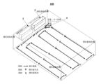
-
- G—PHYSICS
- G01—MEASURING; TESTING
- G01D—MEASURING NOT SPECIALLY ADAPTED FOR A SPECIFIC VARIABLE; ARRANGEMENTS FOR MEASURING TWO OR MORE VARIABLES NOT COVERED IN A SINGLE OTHER SUBCLASS; TARIFF METERING APPARATUS; MEASURING OR TESTING NOT OTHERWISE PROVIDED FOR
- G01D1/00—Measuring arrangements giving results other than momentary value of variable, of general application
- G01D1/02—Measuring arrangements giving results other than momentary value of variable, of general application giving mean values, e.g. root means square values
-
- G—PHYSICS
- G05—CONTROLLING; REGULATING
- G05D—SYSTEMS FOR CONTROLLING OR REGULATING NON-ELECTRIC VARIABLES
- G05D1/00—Control of position, course, altitude or attitude of land, water, air or space vehicles, e.g. using automatic pilots
- G05D1/02—Control of position or course in two dimensions
- G05D1/021—Control of position or course in two dimensions specially adapted to land vehicles
- G05D1/0231—Control of position or course in two dimensions specially adapted to land vehicles using optical position detecting means
- G05D1/0246—Control of position or course in two dimensions specially adapted to land vehicles using optical position detecting means using a video camera in combination with image processing means
- G05D1/0251—Control of position or course in two dimensions specially adapted to land vehicles using optical position detecting means using a video camera in combination with image processing means extracting 3D information from a plurality of images taken from different locations, e.g. stereo vision
-
- B—PERFORMING OPERATIONS; TRANSPORTING
- B08—CLEANING
- B08B—CLEANING IN GENERAL; PREVENTION OF FOULING IN GENERAL
- B08B5/00—Cleaning by methods involving the use of air flow or gas flow
- B08B5/04—Cleaning by suction, with or without auxiliary action
-
- B—PERFORMING OPERATIONS; TRANSPORTING
- B03—SEPARATION OF SOLID MATERIALS USING LIQUIDS OR USING PNEUMATIC TABLES OR JIGS; MAGNETIC OR ELECTROSTATIC SEPARATION OF SOLID MATERIALS FROM SOLID MATERIALS OR FLUIDS; SEPARATION BY HIGH-VOLTAGE ELECTRIC FIELDS
- B03C—MAGNETIC OR ELECTROSTATIC SEPARATION OF SOLID MATERIALS FROM SOLID MATERIALS OR FLUIDS; SEPARATION BY HIGH-VOLTAGE ELECTRIC FIELDS
- B03C3/00—Separating dispersed particles from gases or vapour, e.g. air, by electrostatic effect
- B03C3/017—Combinations of electrostatic separation with other processes, not otherwise provided for
-
- B—PERFORMING OPERATIONS; TRANSPORTING
- B03—SEPARATION OF SOLID MATERIALS USING LIQUIDS OR USING PNEUMATIC TABLES OR JIGS; MAGNETIC OR ELECTROSTATIC SEPARATION OF SOLID MATERIALS FROM SOLID MATERIALS OR FLUIDS; SEPARATION BY HIGH-VOLTAGE ELECTRIC FIELDS
- B03C—MAGNETIC OR ELECTROSTATIC SEPARATION OF SOLID MATERIALS FROM SOLID MATERIALS OR FLUIDS; SEPARATION BY HIGH-VOLTAGE ELECTRIC FIELDS
- B03C3/00—Separating dispersed particles from gases or vapour, e.g. air, by electrostatic effect
- B03C3/32—Transportable units, e.g. for cleaning room air
-
- B—PERFORMING OPERATIONS; TRANSPORTING
- B03—SEPARATION OF SOLID MATERIALS USING LIQUIDS OR USING PNEUMATIC TABLES OR JIGS; MAGNETIC OR ELECTROSTATIC SEPARATION OF SOLID MATERIALS FROM SOLID MATERIALS OR FLUIDS; SEPARATION BY HIGH-VOLTAGE ELECTRIC FIELDS
- B03C—MAGNETIC OR ELECTROSTATIC SEPARATION OF SOLID MATERIALS FROM SOLID MATERIALS OR FLUIDS; SEPARATION BY HIGH-VOLTAGE ELECTRIC FIELDS
- B03C3/00—Separating dispersed particles from gases or vapour, e.g. air, by electrostatic effect
- B03C3/34—Constructional details or accessories or operation thereof
- B03C3/88—Cleaning-out collected particles
-
- B—PERFORMING OPERATIONS; TRANSPORTING
- B08—CLEANING
- B08B—CLEANING IN GENERAL; PREVENTION OF FOULING IN GENERAL
- B08B5/00—Cleaning by methods involving the use of air flow or gas flow
- B08B5/04—Cleaning by suction, with or without auxiliary action
- B08B5/043—Cleaning travelling work
-
- B—PERFORMING OPERATIONS; TRANSPORTING
- B08—CLEANING
- B08B—CLEANING IN GENERAL; PREVENTION OF FOULING IN GENERAL
- B08B6/00—Cleaning by electrostatic means
-
- G—PHYSICS
- G01—MEASURING; TESTING
- G01D—MEASURING NOT SPECIALLY ADAPTED FOR A SPECIFIC VARIABLE; ARRANGEMENTS FOR MEASURING TWO OR MORE VARIABLES NOT COVERED IN A SINGLE OTHER SUBCLASS; TARIFF METERING APPARATUS; MEASURING OR TESTING NOT OTHERWISE PROVIDED FOR
- G01D21/00—Measuring or testing not otherwise provided for
- G01D21/02—Measuring two or more variables by means not covered by a single other subclass
-
- G—PHYSICS
- G05—CONTROLLING; REGULATING
- G05D—SYSTEMS FOR CONTROLLING OR REGULATING NON-ELECTRIC VARIABLES
- G05D1/00—Control of position, course, altitude or attitude of land, water, air or space vehicles, e.g. using automatic pilots
- G05D1/02—Control of position or course in two dimensions
- G05D1/021—Control of position or course in two dimensions specially adapted to land vehicles
- G05D1/0212—Control of position or course in two dimensions specially adapted to land vehicles with means for defining a desired trajectory
- G05D1/0221—Control of position or course in two dimensions specially adapted to land vehicles with means for defining a desired trajectory involving a learning process
-
- G—PHYSICS
- G05—CONTROLLING; REGULATING
- G05D—SYSTEMS FOR CONTROLLING OR REGULATING NON-ELECTRIC VARIABLES
- G05D1/00—Control of position, course, altitude or attitude of land, water, air or space vehicles, e.g. using automatic pilots
- G05D1/02—Control of position or course in two dimensions
- G05D1/021—Control of position or course in two dimensions specially adapted to land vehicles
- G05D1/0255—Control of position or course in two dimensions specially adapted to land vehicles using acoustic signals, e.g. ultra-sonic singals
-
- G—PHYSICS
- G05—CONTROLLING; REGULATING
- G05D—SYSTEMS FOR CONTROLLING OR REGULATING NON-ELECTRIC VARIABLES
- G05D1/00—Control of position, course, altitude or attitude of land, water, air or space vehicles, e.g. using automatic pilots
- G05D1/20—Control system inputs
- G05D1/24—Arrangements for determining position or orientation
- G05D1/247—Arrangements for determining position or orientation using signals provided by artificial sources external to the vehicle, e.g. navigation beacons
-
- G—PHYSICS
- G05—CONTROLLING; REGULATING
- G05D—SYSTEMS FOR CONTROLLING OR REGULATING NON-ELECTRIC VARIABLES
- G05D1/00—Control of position, course, altitude or attitude of land, water, air or space vehicles, e.g. using automatic pilots
- G05D1/40—Control within particular dimensions
- G05D1/43—Control of position or course in two dimensions [2D]
-
- G—PHYSICS
- G05—CONTROLLING; REGULATING
- G05D—SYSTEMS FOR CONTROLLING OR REGULATING NON-ELECTRIC VARIABLES
- G05D1/00—Control of position, course, altitude or attitude of land, water, air or space vehicles, e.g. using automatic pilots
- G05D1/60—Intended control result
- G05D1/648—Performing a task within a working area or space, e.g. cleaning
-
- G—PHYSICS
- G05—CONTROLLING; REGULATING
- G05D—SYSTEMS FOR CONTROLLING OR REGULATING NON-ELECTRIC VARIABLES
- G05D1/00—Control of position, course, altitude or attitude of land, water, air or space vehicles, e.g. using automatic pilots
- G05D1/60—Intended control result
- G05D1/656—Interaction with payloads or external entities
- G05D1/672—Positioning of towed, pushed or suspended implements, e.g. ploughs
-
- G—PHYSICS
- G05—CONTROLLING; REGULATING
- G05D—SYSTEMS FOR CONTROLLING OR REGULATING NON-ELECTRIC VARIABLES
- G05D1/00—Control of position, course, altitude or attitude of land, water, air or space vehicles, e.g. using automatic pilots
- G05D1/60—Intended control result
- G05D1/656—Interaction with payloads or external entities
- G05D1/689—Pointing payloads towards fixed or moving targets
-
- G—PHYSICS
- G05—CONTROLLING; REGULATING
- G05D—SYSTEMS FOR CONTROLLING OR REGULATING NON-ELECTRIC VARIABLES
- G05D2105/00—Specific applications of the controlled vehicles
- G05D2105/10—Specific applications of the controlled vehicles for cleaning, vacuuming or polishing
-
- G—PHYSICS
- G05—CONTROLLING; REGULATING
- G05D—SYSTEMS FOR CONTROLLING OR REGULATING NON-ELECTRIC VARIABLES
- G05D2105/00—Specific applications of the controlled vehicles
- G05D2105/80—Specific applications of the controlled vehicles for information gathering, e.g. for academic research
-
- G—PHYSICS
- G05—CONTROLLING; REGULATING
- G05D—SYSTEMS FOR CONTROLLING OR REGULATING NON-ELECTRIC VARIABLES
- G05D2109/00—Types of controlled vehicles
- G05D2109/20—Aircraft, e.g. drones
- G05D2109/26—Lighter-than-air aircraft
-
- G—PHYSICS
- G05—CONTROLLING; REGULATING
- G05D—SYSTEMS FOR CONTROLLING OR REGULATING NON-ELECTRIC VARIABLES
- G05D2111/00—Details of signals used for control of position, course, altitude or attitude of land, water, air or space vehicles
- G05D2111/30—Radio signals
Definitions
- This application relates to the technical field of information, and in particular to a collection device control method, collection device and spatial system.
- Environmental data When detecting environmental data, it is possible to acquire environmental data at a given position by moving the collecting device along a given route and detecting it when it reaches a given position.
- Environmental data may be, for example, parameters such as air quality, dust concentration, temperature, humidity.
- the inventor of the present application found that when using a collection device to detect environmental data in the space of the target area, the collection device may not be able to reach some area, and the unreachable area may be an area smaller than the size of the collection device, such as some corner, the area above the cabinet, the area behind the television, or the area around the blockage in the space.
- the embodiments of the present application provide a collection device control method, a collection device, and a space system that can detect environmental data in an unreachable area by setting a detection route for the collection device based on the unreachable area and calculating environmental data in the unreachable area.
- obtaining information in space of the target region setting a detection path for a collection device based on an unreachable area in space of the target area; obtaining environmental data, including environmental data of the unreachable area, detected as the collecting apparatus moves along the detection path within the space of the target area.
- an acquisition device for acquiring information in space of the target region; a control device for setting a detection path based on an unreachable area in the space of the target area; a detection device for acquiring environmental data, including environmental data of said unreachable region, detected as the device moves along said detection path within the space of said target region.
- a beneficial effect of the embodiments of the present application is that the detection path of the collection device is set based on the unreachable area, the environmental data of the unreachable area is calculated, and the environmental data of the unreachable area of the collection apparatus can be detected.
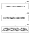
- FIG. 1 is a schematic diagram of a control method for a collection device according to Example 1 of the present application
- FIG. FIG. 4 is a schematic diagram of calculating environmental data within the unreachable area based on environmental data of the surrounding area
- FIG. 3 is a schematic diagram of detecting environmental data in an unreachable area by a sub-collection device
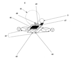
- 1 is a schematic diagram of a collection device and a sub-collection device
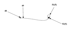
- FIG. FIG. 10 is a schematic diagram of a state in which the traction wire is retracted
- FIG. 10 is a schematic view of the puller wire deployed
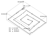
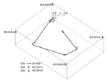
- FIG. 11 is a schematic diagram of a Z-shaped detection path
- FIG. 11 is a schematic diagram of a circular detection path
- FIG. 4 is a schematic diagram of a detection path by region;
- FIG. 11 is a schematic diagram of how the collection device adjusts the detection path;
- FIG. 5B is another schematic diagram of how the collection device adjusts the detection path;
- FIG. 11 is a further schematic diagram of how the collection device adjusts the detection path;
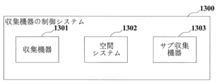
- Figure 2 is a schematic diagram of a control system for a collection device; 1 is a schematic diagram of a spatial system;
- FIG. 13 is a schematic diagram of how the spatial system 1302 calculates the coordinates of the radio signal receiving means;
- FIG. 1 is a schematic diagram of distances between multiple wireless transmitting/receiving devices;
- FIG. 1 is a schematic diagram of a coordinate system;
- FIG. 2 is a schematic diagram of a collection device according to Example 2 of the present application;
- FIG. 2 is a schematic diagram of a collection device according to Example 2 of the present application;
- FIG. 2 is a schematic diagram of a collection device according to Example 2 of the present application;
- FIG. 1 is a schematic diagram of a dust removal system;
- FIG. 2 is a schematic diagram of a cleaning channel 2;
- FIG. 3 is a schematic diagram of an electrostatic application channel 3;
- FIG. 4 is a schematic diagram of how the control device 40 controls the collection device 1;
- FIG. Fig. 4 is another schematic diagram of how the control device 40 controls the collection device 1;
- FIG. 4 is a schematic diagram of a method of controlling a control device to move a collection device according to a set movement path;
- 24 is a schematic diagram of operation 2401;
- terms such as “first” and “second” are used to distinguish different elements from designations, but do not indicate the spatial arrangement or temporal order of these elements, and these elements should not be limited by these terms.
- the term “and/or” includes any one and all combinations of one or more of the associated listed terms.
- the terms “include,” “include,” “have,” etc. refer to the presence of the stated feature, element, element or component, but do not exclude the presence/addition of one or more other features, elements, elements or components.
- Embodiment 1 of the present application provides a collection device, a control method for the collection device, and a spatial system.
- FIG. 1 is a schematic diagram of a control method for a collection device according to an embodiment of the present application.
- the control method of the collection device consists of: an act 101 of obtaining information in space of the target area; an act 102 of setting a detection path for a collection device based on unreachable regions in space of said target region; an operation 103 of obtaining environmental data, including environmental data of said unreachable region, detected as a collection device moves along said detection path within the space of said target region.
- the detection path of the collecting device is set based on the unreachable area, and the environmental data of the unreachable area is calculated, so that the collecting apparatus can detect the environmental data of the unreachable area.
- the collection device can move horizontally, for example, move on the ground or move on the surface of objects such as furniture and/or walls.
- the collection device may also move vertically, for example, the collection device may have propellers or levitation parts (eg, levitation balloons) to control vertical movement of the collection device.
- propellers or levitation parts eg, levitation balloons
- the collection device can be turned on in response to a control command (e.g., generated based on the user's voice or gesture) and moved according to the detection path set in operation 102.
- a control command e.g., generated based on the user's voice or gesture
- the collecting device moves to a predetermined one or more positions on the detection path, it can rest for a while (e.g., for a minute or several minutes), detect the environmental data at the position, and then continue to move, so that the detection can be performed after the air conditions around the collecting device have stabilized, and the detection accuracy is higher and it is more accurate to collect the environmental data after the air conditions have stabilized, or the collecting device can collect the environmental data while moving, for example, the collecting device detects along the detection path.
- the collection device can immediately move to a predetermined position for detection, or move to a predetermined position at a predetermined time for detection.
- the environmental data detected by the collection device may be air quality (e.g., concentration of particulate matter in air), air temperature, air humidity, carbon dioxide ( CO2 ) concentration, volatile organic VOC concentration, formaldehyde concentration, and the like.
- air quality e.g., concentration of particulate matter in air
- air temperature e.g., air temperature
- air humidity e.g., air humidity
- CO2 carbon dioxide
- volatile organic VOC concentration e.g., formaldehyde concentration
- the acquisition device can perceive or scan the spatial layout of the target area with a camera, thereby obtaining information in the space of the target area, or the acquisition apparatus can obtain information in the space of the target area from a building information model (BIM).
- BIM building information model
- the space of the target area may be, for example, at least a partial area in a room.
- unreachable areas within the target space can be identified.
- the unreachable area may be an area whose size is smaller than the size of the collection equipment so that the collection equipment cannot reach the area, for example, the unreachable area may be any corner of the room, or the area between a physical obstacle such as furniture or appliances in the room and the wall, roof or ground. Information of physical obstacles can also be stored.
- information of the environmental equipment in the space of the target area such as type information, position information, size information, etc.
- the environmental equipment is, for example, at least one of purifiers, air conditioners, fresh air systems, and humidifiers.
- one or more detection paths can be established for each unreachable area, each detection path being parallel to the horizontal direction, parallel to the vertical direction, or presenting an angle to the horizontal direction.
- the detection path may be straight or curved.
- the collection device moves along the detection path, in addition to being able to gradually approach the unreachable area, once the collection device reaches a certain position, the movement of the collection device can be avoided by switching the detection path away from the unreachable area.
- the collection device can immediately move to a predetermined position for detection, or can move to a predetermined position at a predetermined time for detection.
- the collection device may calculate environmental data within the unreachable area based on environmental data of areas surrounding the unreachable area.
- environmental data within the unreachable area can be calculated based on environmental data of areas surrounding the unreachable area detected by different detection paths. Specifically, for each detection path, the relationship between the position around the unreachable area and the environmental data can be identified (for example, a relational expression between the two can be established, and the relational expression may be linear or nonlinear), and based on the identified relationship between the position and the environmental data, the environmental data within the unreachable area is calculated.
- FIG. 2 is a schematic diagram of calculating environmental data in the unreachable area based on environmental data in the surrounding area.
- the unreachable region is ⁇
- r is the radius of the region ⁇
- the detection paths set for the region ⁇ are path S1, path S2 and path S3, where path S1, path S2 and path S3 are straight lines, for example.
- the detected environmental data are trn, ..., tr6, tr5, tr4, tr3, tr2, tr1, respectively.
- the environmental data within area ⁇ can be calculated for each detection path.
- three environmental data pr1, pr2, and pr3 are obtained by calculating the environmental data in the area ⁇ for the paths S1, S2, and S3 in FIG.
- the average value of the plurality of (for example, three) environmental data or the average value of a pair of environmental data having the smallest mean squared error (MSE) in the plurality of environmental data can be used as the environmental data of the unreachable region ⁇ .
- MSE mean squared error
- the mean value of pr1, pr2, and pr3 is set as the environmental data for the unreachable region ⁇ .
- Equation 1 the mean squared error can be calculated by Equation 1 below.
- y i and y j represent both of the environmental data pr1, pr2 and pr3.
- the time difference between different position points can be used as an influencing factor of the environmental data.
- environmental data at different times at different location points can be input into a temporal storage network model, and environmental data with time features can be output.
- a long short-term memory network model (AI) is acquired, and the long short-term memory network model is stored.
- AI long short-term memory network model
- the environmental data of the space ⁇ is calculated, a plurality of environmental data (e.g., three environmental data pr1, pr2, pr3) are obtained, and if the same collection device moves along different detection paths at different times, the plurality of environmental data can embody the information associated with the time change of the environmental data. time) environmental data can be acquired.
- the environmental data in the unreachable area can also be detected by the sub-collection device.
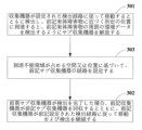
- FIG. 3 is a schematic diagram of a method for detecting environmental data in unreachable areas by sub-collection devices.
- a method for detecting environmental data in an unreachable area by a sub-collection device includes: an operation 301 of releasing the sub-collection device so that the collection device moves along the set detection path and detects it, and when it reaches a predetermined position approaching the physical obstacle, it detects environmental data around the physical obstacle; an operation 302 in which, if the sub-collection device has completed detection, the collection device retrieves the sub-collection device while the collection device continues to move and detect according to the set detection path.
- the position of the collection device can be measured, and a sub-detection path for the sub-collection device can be set based on the space or position occupied by the position of the collection device and the unreachable region.
- the sub-collection device moves along the sub-detection route set for the sub-collection device, detects environmental data, and uploads the obtained environmental data to the database.
- the sub-collection device may be a probe extending from the collection device or another movable object that can be detached from the collection device.
- the sub-collection device can be connected to the collection device by a pull wire, which can ensure a strong connection between the sub-collection device and the collection device. Also, there may be no pull wires between the sub-collection device and the collection device.
- FIG. 4 is a schematic diagram of the collection device and the sub-collection device
- FIG. 5 is a schematic diagram with the traction wire retracted
- FIG. 6 is a schematic diagram with the traction wire deployed.
- the collection device 4 The levitation part 41 that provides the power to raise the collecting device 4, and can be a balloon having an interesting shape such as an elliptical shape or a circular shape for stable flight, a cloud shape or an animal shape that can enhance the fun and achieve a calming effect, etc.; an acquisition device (not shown in FIG. 4) for acquiring information in space of the target area; a drive 43, which can be, for example, a propeller, to move the collection device; a transmission device (not shown in FIG.
- a detection device 44 for detecting environmental data and transmitting the environmental data to the transmission device; and a controller 45 that controls the drive 43 so that the collection device 4 flies along preset or updated detection paths, including detection paths established based on unreachable regions in space of the target area.
- the collection device 4 further comprises a battery 46 that provides electrical energy to the collection device 4 .
- the collection device 4 may be provided with a sub-detection device 5 that can be detached from the collection device 4 and collected by the collection device 4 .
- the sub-detection device 5 when the collection device 4 is in a position approaching the unreachable area, the surface with the sub-detection device 5 is directed toward the unreachable region, and the launch plate 47 on the collection device 4 causes the sub-detection device 5 to be launched into the unreachable region. At the farthest distance, the sub-detection device 5 is suspended in the air by the balloon 51 (shown in FIGS. 5 and 6), the detection module 52 (shown in FIGS.
- the sub-detection device 5 detects environmental data, and after the detection by the sub-detection device 5 is completed, the pulling wire 49 pulls the sub-detection device 5 back and the sub-detection device 5 is recovered by the collection device 4 by driving the unidirectional rotary damper 48 to rotate by the motor.
- the environmental data detected by the collecting device 4 and the sub-detecting device 5 can both be uploaded to a database, and the database will fit the distribution map of the environmental data in the space of the target area based on the environmental data at different times at different locations.
- the detection path set for the collection device includes a Z-shaped detection path, a linear detection path, a circular detection path, or a region-specific detection path.
- FIG. 7 is a schematic diagram of a Z-shaped detection path
- FIG. 8 is a schematic diagram of a circular detection path
- FIG. 9 is a schematic diagram of detection paths for each region.
- the space of the target area is divided into multiple areas, whereby the collecting device can move to each area, and in each area the collecting apparatus can move according to a random detection path.
- a detection path can be set based on the information of the target area. For example, if there is no tall obstacle in the target area, the circular detection path can be preferentially set. If there is an obstacle such as a pillar in the target area, the predetermined Z-shaped path can be set.
- the detection path can be adjusted or updated as the collection device moves along the detection path.
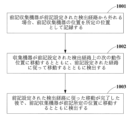
- FIG. 10 is a schematic diagram of how the collection device coordinates the detection path. As shown in Figure 10, one way the collection device adjusts the detection path is to: an operation 1001 of recording the location of the collection device as a predetermined location if the collection device deviates from the set detection path; an operation 1002 of a collection device moving to a next operating position on said set detection path and moving according to said set path and detecting; and an operation 1003 of moving the collection device to the predetermined position and detecting after completing the movement along the set detection path.
- operation 1001 when the collection device moves along the set detection path, it is determined whether the collection device is off the set detection path. For example, it is determined whether the offset distance of the current position of the collection device with respect to the detection path according to the location information of the collection device exceeds a threshold.
- the current position of the collection device can be recorded as the predetermined position.
- the collection device moves from the current position to the next operating position on the set detection path, and moves and detects according to the set path. This allows the collection device to return to the set detection path in a timely manner.
- the operating position refers to a plurality of positions set in advance on the detection path.
- the collection device can return to the predetermined position marked in operation 1001 and detect again.
- FIG. 11 is another schematic diagram of how the collection device coordinates the detection path.
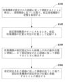
- another way the collection device adjusts the detection path is to: an operation 1101 in which the collection device moves along a set route and detects, and obtains the state of the environmental device at a position approaching the environmental device; an act 1102 of recording the location of the collection device as a predetermined location when the environmental device is turned on; an operation 1103 of collecting device moving to the next operating position on said set path and moving according to said set path and detecting; and detecting 1104 the collection device moving to the predetermined location after completing movement along the set path.
- operation 1101 when the collection device moves along the set detection path, it is determined based on the information collected in operation 101 whether it approaches the environmental device, and at a position approaching the environmental device (for example, at a position away from the environmental device by a predetermined distance), it is determined whether the environmental device is turned on, for example, by detecting wind speed, temperature, humidity, etc., or by receiving an electromagnetic signal, etc. emitted when the environmental device operates.
- the collection device moves along the set detection path and detects.
- the collection device moves from the current position to the next operating position on the set detection path, and moves and detects along the set path. This allows the collection device to return to the set detection path in a timely manner.
- the operating position refers to a plurality of positions set in advance on the detection path.
- the collection device can return to the predetermined position marked in operation 1102 and detect again, for example, if the environmental device is turned off, return to the predetermined position marked in operation 1102 and detect again.
- Figure 12 is a further schematic illustration of how the collection device coordinates the detection path.
- a further method for the collection device to adjust the detection path is to: an operation 1201 of detecting the collection device as it moves along the set route and acquiring the state of the environmental device at a position approaching the environmental device; operation 1202 , when the environmental device is turned on, the controller of the collection device controls the environmental device to stop operating; and an operation 1203 of continuing detection according to the established path.
- operation 1201 when the collection device moves along the set detection path, it is determined based on the information collected in operation 101 whether or not it approaches the environmental device, and at a position approaching the environmental device (for example, at a position separated from the environmental device by a predetermined distance), it is determined whether the environmental device is turned on, for example, by detecting wind speed, temperature, humidity, etc., or by receiving an electromagnetic signal, etc. emitted when the environmental device is running.
- the collection device moves along the set detection path and detects.
- the controller of the collection device can control the environmental device to stop operating. This avoids the airflow during operation of the environmental equipment from interfering with the movement of the collection equipment.
- the collection device can continue motion and detection according to the set path.
- Embodiments of the present application further provide a collection device control system.
- Figure 13 is a schematic diagram of the control system of the collection device; As shown in FIG. 13, the collection device control system 1300 includes: a collection device 1301 that is mobile and that detects environmental data; a spatial system 1302 for positioning the collection device.
- the control device (not shown in FIG. 13) of the collection device 1301 controls the collection device 1301 to move along the set detection path, and in addition, the control device can control the detection device of the collection device 1301 to detect environmental data.
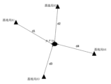
- FIG. 14 is a schematic diagram of the spatial system.
- spatial system 1302 includes: radio signal receiving means T0, which can be, for example, a tag, provided in the collecting device and for determining the position of the collecting device in space; two or more radio transmitting/receiving devices, for example A1, A2, A3, A4 in FIG. 14, for example base stations for transmitting and receiving radio signals, for communicating with the radio signal receiving means T0; a calculation module 1401 for determining the position of the radio signal receiving means T0 based on the distance between the radio signal receiving means T0 and each of the radio transmitting/receiving devices (A1-A4) and the distance between two or more radio transmitting/receiving devices.
- radio signal receiving means T0 can be, for example, a tag, provided in the collecting device and for determining the position of the collecting device in space
- two or more radio transmitting/receiving devices for example A1, A2, A3, A4 in FIG. 14, for example base stations for transmitting and receiving radio signals, for communicating with the
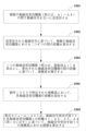
- FIG. 15 is a schematic diagram of how the spatial system 1302 calculates the coordinates of the wireless signal receiving means
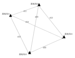
- FIG. 16 is a schematic diagram of the distance between multiple wireless transceivers
- FIG. 17 is a schematic diagram of the coordinate system.
- the method for calculating the coordinates of the radio signal receiving means T0 is an operation 1501 of transmitting and receiving wireless signals between a plurality of wireless transmitting/receiving devices (eg, A1-A4); An operation 1502 of calculating distances between two of a plurality of wireless transmitting/receiving devices based on the transmitted and received wireless signals, as in FIG. an operation 1502 that can calculate a distance based on the time of arrival; An operation 1503 of establishing a coordinate system with one wireless device (e.g., base station A1) as the origin and based on the calculated distances between the wireless devices, establishing a coordinate system when there are four wireless devices, as shown in FIG. It may be a planar coordinate system, i.e.
- the calculating module 1401 includes an operation 1505 of calculating the coordinates in the coordinate system of the radio signal receiving means T0 based on the distances d1, d2, d3, d4 (shown in FIG. 14) between the radio signal receiving means T0 and each radio transmitting/receiving device, and an operation 1505 capable of calculating the distance between the radio signal receiving means T0 and each radio transmitting/receiving device based on the time of arrival.
- the method of positioning by the spatial system 1302 is not limited to that shown in FIG.
- the spatial system 1302 may position based on Ultra Wide Band (UWB), or may position based on Bluetooth®.
- UWB Ultra Wide Band
- the ultra-wideband technology is a technology of wireless carrier wave communication, which uses nanosecond-level non-sinusoidal narrow pulses to transmit data without using sinusoidal waves, so it occupies a wide spectrum range.
- the collection equipment 1301 may perform positioning using an inertial navigation device provided in the collection equipment 1301 instead of performing positioning based on the spatial system 1302 .
- the collection device control system can further include a sub-collection device 1303 .
- a sub-collection device 1303 is provided in the collection device 1301 and can leave the collection device 1301 and return to the spatial system 1302 .
- Collection device 1301 has the same structure and description as collection device 4, sub-collection device 1303 is the same as sub-detection device 5, and for descriptions of collection device 1301 and sub-collection device 1303, reference can be made to the descriptions for collection device 4 and sub-detection device 5 in FIGS.
- the example includes the following operations. S1, the collection device leaves the automatic charging and refueling station (ie, origin) and begins flight. S2, the collecting device obtains the information in the space of the target area (such as the floor plan or layout diagram of the space of the target area), and sets different detection paths according to the unreachable area. S3, follow the set detection path to reach the detection position (ie, motion position, motion spot, etc.) on the detection path. S4, stay at each detection position for a preset time and detect environmental data (for example, air quality); S5, after completing the detection, fly to the next detection position according to the set detection path.
- S1 the collection device leaves the automatic charging and refueling station (ie, origin) and begins flight.
- S2 obtains the information in the space of the target area (such as the floor plan or layout diagram of the space of the target area), and sets different detection paths according to the unreachable area.
- S3, follow the set detection path to reach the detection
- the air quality of the space is detected by staying at the detection positions of S6 and S5 for a preset time. S7, S5 and S6 are repeated until all detection paths are passed. S8, upload the environmental data to the database and generate an environmental distribution map in the space of the target area; S9, return to the automatic charging/gas filling station for charging and gas filling;
- the preset stay time can be set to, for example, 1 minute. Also, without performing the operation S2, that is, without acquiring the information in the space of the target area, omitting S2, cruising to detect the environmental data, and uploading the detected environmental data to the server, generate an accurate environmental distribution map, and prepare for the next environmental cleaning or environmental purification.
- the collection device can control the environmental device to temporarily stop operating by transmitting a signal to the environmental device by infrared rays or the like, or when it meets the device in operation on the detection route, the collection device avoids the environmental device, and after the environmental device stops operating, the collection device can further move to a detection position near the environmental device and detect it.
- environmental equipment can include air conditioners, purifiers, humidifiers, cleaning robots, fresh air equipment, and the like.
- the collection device can suspend the process of flying along the detection route, fly to the charging/gas filling station, and perform charging and gas filling. If there are multiple charging/gas filling stations, the collection device calculates the closest charging/gas filling station to the current location and flies to the nearest charging/gas filling station to charge or gas.
- a collection device charging flow may include the following actions.
- S11 there are electromagnets in the positive and negative terminals of the charging interface of the automatic charging and gas filling station, and the charging port of the collecting device is ferrous metal.
- S12 when the charging station detects that the collection equipment is approaching, it supplies power to the electromagnets of the positive and negative terminals of the charging interface of the automatic charging and gas filling station to charge the electromagnets;
- S13 the charger of the collection equipment is closely adsorbed and charged after contacting the charging interface of the automatic charging and gas filling station;
- S14 after the electricity on the collection equipment is fully charged or when a start command is received, the electromagnet of the charging interface is de-energized and loses magnetism, and the collection equipment can fly away from the automatic charging and gas filling station.
- the collection device gas filling flow may include the following actions.
- S21 the gas filling interface of the automatic charging and gas filling station has an electromagnet, is a circular mouth and the outermost surface is a sand-grinding surface;
- S22 the charging station powers the electromagnet of the gas filling interface of the automatic charging and gas filling station to charge the electromagnet when it detects that the collection equipment is approaching;
- S23 the charger of the collection equipment is tightly adsorbed after contacting the charging interface of the automatic charging and gas filling station;
- S24 the helium gas is output from the gas filling port of the automatic charging and gas filling station, and the gas filling port of the collecting device is a check valve, which can only fill gas and not let it out.
- S25 after the electricity on the collection equipment is fully charged or when the departure command is received, the electromagnet of the gas charging interface is de-energized and loses magnetism, and the collection equipment can fly away from the automatic charging and gas filling station.
- the detection path of the collection device based on the unreachable area, calculate the environmental data of the unreachable area, and thereby detect the environmental data of the unreachable area of the collection apparatus.
- Example 2 of the present application provides a collection device and a control method for the collection device.
- the collection device can be used in a dust removal system.
- FIG. 18A is a schematic diagram of a collection device according to Example 2 of the present application.
- the collection device 1 includes a levitation unit 10, a drive device 20, a detection device 30, and a control device 40.
- the control device 40 As shown in FIG. 18A, the collection device 1 includes a levitation unit 10, a drive device 20, a detection device 30, and a control device 40.
- the inside of the floating part 10 can be filled with gas to provide power for raising the collection device 1, and static electricity can be generated on the outer surface of the floating part 10.
- the material of the floating part 10 is an insulating material such as plastic or rubber.
- the driving device 20 drives the collecting device 1 to move.
- the detection device 30 may detect environmental data, which may be transmitted to the control device 40 or to a communication device (not shown) of the collection equipment.
- the control device 40 controls the driving device 20 to drive the collecting device 1 to move along the dust removal path, and the floating part 10 charged with static electricity attracts dust in the environment while the collecting device 1 moves along the dust removal route.
- the collecting device has a levitation part whose surface is charged with static electricity and whose interior can be filled with gas, so that the levitation part itself can not only provide power for the collection device to rise, but also can be used to attract dust. Therefore, dust collection efficiency can be improved, energy can be saved, and costs can be reduced.
- control device 40 may further have the functions that the control device 45 in the first embodiment has, so that the control device 40 can execute the control method described in the first embodiment.
- the levitation part 10 has a spherical shape, but the present application is not limited thereto.
- the levitation part 10 may have an oval shape, a cloud shape, an animal shape, or the like.
- the driving device 20 includes a battery 21 and a plurality of (for example, two or more) propellers 22.
- the plurality of propellers 22 are provided to evenly surround the levitation section 10, and the plurality of propellers 22 are provided on the same plane.
- a battery 21 is fixed below the floating portion 10 .
- the propeller 22 can not only make the flight of the collection device 1 more stable, but also accelerate the settling of particulate matter on the ground, reduce the number of particulate matter inhaled by humans, and improve the dust removal effect.
- the detection device 30 may be provided on the levitation section 10 and positioned below the levitation section 10, for example.
- the detection device 30 may include a first dust sensor capable of detecting the concentration of dust in the environment based on the thermal image.
- the detection device 30 can further detect at least one of environmental data such as air temperature, air humidity, carbon dioxide (CO 2 ) concentration, volatile organic matter (VOC) concentration, formaldehyde concentration, and carbon monoxide (CO) concentration.
- the dust removal system can further include a second detection device, the second detection device can include a second dust sensor (not shown), the second dust sensor can be installed at a fixed position in the room, for example, a predetermined number of sensors are distributed in the positioning base station or other positions in the room, the second dust sensor can detect the concentration of dust at the fixed position, so that the concentration data of the dust detected by the second dust sensor and the first , the dust concentration data detected by the dust sensor can be combined, thereby more accurately fitting the distribution of dust concentration in the target area (eg, indoors).
- the second detection device can further detect at least one of environmental data such as air temperature, air humidity, carbon dioxide (CO 2 ) concentration, volatile organic matter (VOC) concentration, formaldehyde concentration, carbon monoxide (CO) concentration.
- the environment data detected by the detection device 30 and/or the second detection device can be transmitted to the server to generate environment data distribution information of the target area (for example, indoors), where the environment data distribution information is, for example, an environment data distribution map.
- the server can receive environmental data and location data corresponding to the environmental data, use a machine learning model to update the environmental data distribution map using the received location data and environmental data, and display the environmental data distribution map of the target area.
- the environmental data distribution information may reflect environmental data at a certain time, may reflect environmental data at a certain time period, or by introducing a neural network, the environmental data distribution information may reflect environmental data predicted at a certain future time or time period.
- control device 40 can not only control the drive device 20 to drive the collection facility 1 to move along the dust removal path, but also control the drive device 20 to drive the collection facility 1 to move along the triboelectrification path and/or the dust collection path.
- the dust and static electricity attracted to the surface of the floating portion 10 are removed in the dust collection path, and static electricity is generated and charged on the surface of the floating portion 10 in the triboelectrification path.
- the dust collecting path, the triboelectrification path and the dust removal path form one complete operation path of the collecting device 1, which can realize the automation of the operation flow. Prepare for the next dust removal by charging the surface of the dust with static electricity again.
- FIG. 18B is another schematic diagram of a collection device according to an embodiment of the present application.
- the collection device 1b includes a float (not shown), a drive device 20, a detection device 30, a control device 40, a sponge 50, an atomization sheet 60, and a traction device 70.
- the description of the levitation section (not shown), the drive device 20, the detection device 30, and the control device 40 is the same as in FIG. 1, and will not be repeated.
- the sponge 50 may be suspended below the control device 40, and an atomizing sheet 60 is provided below the sponge 50, and the atomizing sheet 60 can atomize the water in the sponge 50 and output it.
- Four retractors 70 can retract sponge 50 and atomized sheet 60 .
- the collection device 1b can improve the humidity in the environment.
- FIG. 18C is a further schematic diagram of a collection device according to an embodiment of the present application.
- the collection device 1c includes a levitation unit (not shown), a drive device 20, a detection device 30, a control device 40, a traction device 70, and an air agitating net 80.
- the air agitating screen 80 may be a lightweight, air impermeable screen, such as polyethylene.
- the air stirring net 80 is pulled by the traction device 70 .
- the air agitating net 80 can accelerate air circulation in the room by promoting air flow.
- FIG. 18C shows a state in which the air agitating net 80 is open, and if the air agitating net 80 does not need to operate, the air agitating net 80 may be retracted.
- the collection device 1 will be described as an example, and similar descriptions apply to the collection device 1b and the collection device 1c as well.
- FIG. 19 is a schematic diagram of a dust removal system to which the collection device according to the second embodiment is applied.
- the collection device 1 is not shown in the dust removal system 100 of FIG.
- the dust removal system 100 further has at least one of a cleaning channel 2, an electrostatic application channel 3, and a charging station (e.g., charging/gas filling spot) 4.
- the cleaning channel 2 can be located on the dust collecting path
- the static electricity applying channel 3 can be located on the triboelectrification path
- the charging station 4 can be the starting point from which the collecting device 1 takes off, or the starting point from which the collecting device 1 takes off again after charging halfway.
- cleaning channel 2 includes a first housing 21 and a grounded metal structure 22 .
- a ground metal structure 22 is provided on the top of the first housing 21, and the ground metal structure 22 includes, for example, a first base 221 and a first suction port 222, both of which are made of metal material.
- the first suction port 222 is connected to the first housing 21 via the first base 221 .
- the first suction port 222 is used to attract the levitation part 10 of the collection device 1 to the top of the first housing 21 and for the levitation part 10 to discharge static electricity through the ground metal structure 22 .
- the first base 221 may comprise a pulley structure and can move along a pulley track 211 on top of the first housing 21 .
- the cleaning channel 2 further includes a dust suction port 23 provided on at least one side of the first housing 21 and a first wheel slide plate 24.
- the floating part 10 can be moved together (for example, the two first wheel slide plates 24 sandwich the floating part 10 from both sides and move the floating part 10 together), and the dust adsorbed on the surface of the floating part 10 is sucked by generating a negative pressure in the dust suction port 23.
- the electrostatic application channel 3 includes a second housing 31 and an insulating structure 32 .
- An insulating structure 32 is provided on top of the second housing 31 .
- the insulating structure 32 includes, for example, a second base 321 and a second suction port 322, both of which are made of plastic material.
- the second suction port 322 is connected to the second housing 31 via the second base 321 , and the second suction port 322 can suction the floating part 10 to the top of the second housing 31 .
- the second base 321 may comprise a pulley structure and can move along a pulley track 311 on top of the second housing 31 .
- the static electricity applying channel 3 can further include a triboelectric structure 33 provided on at least one side of the second housing 31 and a second wheel slide plate 34 .
- the triboelectric structure 33 may be, for example, a structure of nylon bristles.
- the second wheel slide plate 34 moves the levitation part 10 together (for example, the two second wheel slide plates 34 sandwich the levitation part 10 from both sides and move the levitation part 10 together). Since the triboelectric structure 33 is fixed to the side of the second housing 31, the triboelectric structure 33 can generate static electricity on the surface of the levitation part 10 by friction with the levitation part 10.
- the charging stand 4 can charge the battery of the collection device 1 by wireless charging or magnetic attraction.
- the charging stand 4 may be provided in a base station (for example, the positioning base station 4 in FIG. 19).
- the charging stand 4 may be provided on the ceiling of the room or below the base station.
- the charging stand 4 may be provided at a position having a predetermined distance from the base station.
- the charging stand 4 may have a function of filling the floating portion 10 with gas, so that both charging and gas filling functions can be integrated into the charging stand 4 .
- an electromagnet can be provided at the gas filling port of the charging stand 4, and a magnet can be provided at the gas filling port of the levitation unit 10.
- a check valve is provided at the gas filling port of the floating section 10 to allow gas to enter the floating section 10 and prevent gas leakage within the floating section 10 .
- an independent gas filling stand can be provided to realize the function of filling the floating section 10 with gas.
- a gas filling station may be provided beside a charging station.
- the dust removal system 100 may further include a space system.
- a spatial system can position the collection device 1 .
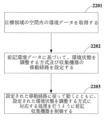
- Figure 22 is a schematic diagram of how the controller 40 controls the collection device 1, which as shown in Figure 22 comprises: an act 2201 of obtaining environmental data in space of the target area; an operation 2202 of setting a method for adjusting environmental conditions and a movement route of the collection device based on the environmental data; and an operation 2203 of controlling the collection device to move according to a set movement path and to perform processing corresponding to a set environmental condition adjustment scheme.
- the environmental data includes at least one of particulate matter concentration in the air (e.g., dust concentration, and/or PM2.5 concentration, and/or PM10 concentration, etc.), air temperature, air humidity, carbon dioxide ( CO2 ) concentration, volatile organics (VOC) concentration, formaldehyde concentration, carbon monoxide (CO) concentration, and the like.
- the environmental data may be environmental data detected by the detecting device 30 and/or the second detecting device, or environmental data distribution information or the like transmitted to the collecting device by the server.
- the manner in which the environmental conditions are adjusted is, for example, by removing (e.g., dedusting) the particulate matter that floats the environment and/or humidifying and/or promoting airflow.
- the environment data within the target area can be improved overall by setting the round-trip cruise path for the collection device 1 to cruise within the target area, for example, by switching the collection device 1 to an automatic cruise mode, the collection device 1 can fly along the automatic cruise route and implement a scheme for adjusting the environmental conditions on the automatic cruise route.
- the automatic cruise mode can be switched to.
- a travel route may be set based on the location corresponding to the environmental data that needs to be improved. For example, based on the acquired environmental data, enumerate several positions where the dust concentration or other environmental data is greater than the threshold, or enumerate several high-ranking positions that rank the dust concentration or other environmental data from top to bottom, start from the starting point (e.g., charging station), calculate the position closest to the starting point in the enumerated positions as the first position point on the movement route, and then calculate the position closest to the first position point in the enumerated positions as the second position point.
- the starting point e.g., charging station
- each position point on the movement path is calculated in turn, and these position points constitute each position point on the movement path, so that the movement path can be set.
- a movement route can be set based on the position corresponding to the environmental data that needs to be improved, so that the collecting device 1 performs intentional environmental adjustment processing for the position corresponding to the environmental data that needs to be improved.
- the distribution of the environmental data is uneven (eg, the mean squared error of the environmental data is greater than a predetermined value), it is possible to switch to the capture mode.
- control device 40 may set a default movement route, which can be, for example, a serpentine route.
- FIG. 23 is another schematic illustration of how the controller 40 controls the collection device 1 .
- the control method includes: an operation 2301 of obtaining spatial information of the target area and/or information of the environmental equipment; an operation 2302 of setting a movement route of the collection device based on the spatial information and/or information of the environmental device; and an operation 2303 of controlling the collection device to move according to the set movement path.
- spatial information of the target area is obtained by scanning the target area or obtained from a building information model (BIM).
- information of the environmental equipment within the target area such as environmental equipment type information, location information, size information, etc., may be further obtained.
- Environmental appliances can include air conditioners, purifiers, humidifiers, cleaning robots, fresh air appliances, and the like.
- a movement path can be set based on the spatial information of the target area.
- the movement path may be a Z-shaped movement path shown in FIG. 7, a circular movement path shown in FIG. 8, or a region-specific movement path shown in FIG. For example, if there is no tall obstacle in the target area, the circular detection path can be preferentially set. If there is an obstacle such as a pillar in the target area, the predetermined Z-shaped path can be set.
- the movement route is set by the environmental equipment, and for example, if the environmental equipment is present on the movement route, the collection device may adjust the movement route so as to bypass the environmental equipment.
- the collection device can return to the vicinity of the environmental device when it is detected that the device has already been turned on. As a result, it is possible to prevent the collection equipment from being deviated from the movement path due to the air current generated during the operation of the environmental equipment.
- the collection device 1 when the collection device 1 flies along the movement route (for example, operation 2303 or operation 2203), when the collection device 1 flies near the environmental equipment, if it detects that the environmental equipment is operating, the collection equipment 1 can transmit an infrared signal or the like to stop the operation of the environmental equipment, thereby preventing the collection equipment from deviating from the movement route due to the air current generated during the operation of the environmental equipment.
- FIG. 24 is a schematic diagram of how the controller controls the collection device to move according to the set movement path, and is used to implement operation 2303 or operation 2203 above.
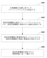
- controlling the collection device 1 by the control device 40 to move along the set movement path is an act 2401 of identifying a cleaning channel based on the location of the collection device; an operation 2402 of moving the collection device into the cleaning channel to remove dust that has been attracted to the collection device; an act 2403 of causing the collection device to enter an electrostatic application channel to generate static electricity on the surface of the collection device; and an operation 2404 of allowing the collection device to move according to the set movement path.
- the operations 2401, 2402, and 2403 may be performed before the collection device 1 starts moving along the set movement path, and the operations 2401, 2402, and 2403 may be performed while the collection device 1 moves along the set movement path. If so, in that case, the movement along the original movement path is temporarily stopped, and operations 2401, 2402, and 2403 are performed to remove the dust adhered to the surface of the levitation unit 10, and the surface of the levitation unit 10 is charged with static electricity again, and then, in operation 2404, the movement along the original movement path can be continued.
- the location of the collection device 1 may be determined based on an inertial navigation device in the spatial system or collection device 1 .
- the controller 40 calculates the distance between each cleaning channel 2 and the collection device 1 and designates the cleaning channel 2 closest to the collection device 1 as the identified cleaning channel.
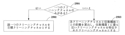
- FIG. 25 is a schematic diagram of operation 2401, and as shown in FIG. an operation 2501 of determining if there is only one cleaning channel within the target area where the collection device 1 is located, and if so, proceeding to operation 2502, else proceeding to operation 2503; an operation 2502 of setting the one cleaning channel as a target cleaning channel;
- An act 2503 of calculating the distance between each cleaning channel and collection device 1 and making the cleaning channel closest to collection device 1 the identified cleaning channel can include, for example, an act 2503 of identifying cleaning channel #1 as the target cleaning channel because the distance from cleaning channel #1 to collection device 1 is d1, the distance from cleaning channel #2 to collection device 1 is d2, and d1 ⁇ d2.
- the controller 40 may control the collection device 1 to enter the targeted cleaning channel 2 .
- a control signal may be sent by controller 40 to cause cleaning channel 2 to begin the cleaning process, or trigger cleaning channel 2 to cause cleaning channel 2 to begin the cleaning process when the collection device enters cleaning channel 2.
- the cleaning process is as follows: the first suction port 222 at the top of the cleaning channel 2 sucks the collecting device 1 to the top by wind force, discharges the static electricity accumulated in the floating portion 10 of the collecting device 1, both sides of the collecting device 1 contact the first wheel slide plate 24, the dust suction ports 23 on both sides of the cleaning channel 2 are turned on to suck dust on the surface of the floating portion 10, and the first suction port 222 at the top of the collecting device moving forward along the cleaning channel 2 while sucking the collecting device 1 and simultaneously moving forward along with the collecting device 1 and the first wheel slide plate 24 .
- control device 40 controls the collecting device 1 to leave the cleaning channel 2 .
- the controller 40 may control the collection device 1 to enter as the electrostatic application channel 3 .
- a control signal may be sent by controller 40 to cause electrostatic application channel 3 to initiate a cleaning process, or trigger electrostatic application channel 3 to initiate an electrostatic application process when a collection device enters electrostatic application channel 3.
- the static electricity applying process is performed by the second suction port 322 at the top of the static electricity applying channel 3 attracting the collecting device 1 to the top by wind force, both sides of the collecting device 1 contacting the second wheel sliding plate 34, and the triboelectric structure 33 being fixed on both sides of the second housing 31, and friction is generated between the levitation part 10 and the triboelectric structure 33 when the collecting device 1 moves forward along the static electricity applying channel 3. and generating static electricity on the surface of the portion 10 .
- control device 40 controls the collection device 1 to leave the static electricity application channel 3 .
- allowing the collection device 1 to move along the set movement route includes moving the collection device 1 to a predetermined position on the movement route and then allowing the collection device 1 to stay there for a predetermined period of time, and/or moving the collection device 1 along the movement route for a predetermined period of time, and/or moving the collection device 1 along the movement route for a predetermined distance.
- the collection device 1 can immediately start moving along the movement route after receiving the control signal, start moving along the movement route at a predetermined time, or move to a predetermined position at a predetermined time.
- the specific shape of the movement path may be a Z-shaped path (eg, FIG. 7), a circular path (eg, FIG. 8), or a random path for each region (eg, FIG. 9).
- the operation flow of the collection device 1 will be described below in one embodiment.
- An example is the following operations:
- the user activates the collection device 1 by voice or gesture S1
- the collection device 1 flies away from the charging station and detects environmental data in the target area (for example, indoors).
- the flying movement route may be a default route (for example, a cruise route) or a movement route set based on the spatial information of the target region and/or the information of the environmental equipment.
- the control device of the collecting device 1 generates a corresponding movement route based on the distribution information of the environmental data to improve the environmental data S3; S4 of acquiring the position of the collection device 1 by the spatial system; searching S5 for the closest cleaning channel 2 from the collection device 1; the collection device 1 enters the cleaning channel 2 S6; S7 the collection device 1 enters the electrostatic application channel 3; S8, in which the collection device 1 moves along the movement path set in S3 and performs at least one of processing for improving environmental data, such as dust removal, humidification, and air flow enhancement; After the processing of the collecting device 1 is completed, the cleaning channel 2 is entered to clean dust on the surface of the floating portion 10 (S9); S10 in which the collection device 1 enters charging or sleep mode.
- the collection device 1 can return to operation S2 again, detect again, and change the movement path in real time based on the new detection result.
- the collection device 1 can stay for a predetermined amount of time when it reaches a predetermined position on the movement path, thereby helping to perform processes such as dust removal, humidification, and air flow enhancement.
- a preset dwell time can be set, for example, to 1 minute. Also, without performing the operation S2, that is, without acquiring the information in the space of the target area, omitting S2, cruising to detect the environmental data, and uploading the detected environmental data to the server, generate an accurate environmental distribution map, and prepare for the next environmental cleaning or environmental purification.
- the collection device 1 can control the environmental device to temporarily stop operating by transmitting a signal to the environmental device by infrared rays or the like, or when it meets the device in operation on the movement route, the collection device 1 avoids the environmental device, and after the environmental device stops operating, the collection device 1 can further move to a detection position near the environmental device and detect it.
- environmental equipment can include air conditioners, purifiers, humidifiers, cleaning robots, fresh air equipment, and the like.
- the collection device 1 can suspend the process of flying along the movement route, fly to the charging/gas filling station, and perform charging or gas filling. If there are multiple charging/gas filling stations, the collecting device 1 calculates the closest charging/gas filling station to the current position, flies to the nearest charging/gas filling station, and charges or fills with gas.
- the charging flow of the collection device 1 can include the following operations. S11, there are electromagnets in the positive and negative terminals of the charging interface of the automatic charging and gas filling station, and the charging port of the collecting device is ferrous metal. S12, when the charging station detects that the collection device 1 is approaching, it supplies power to the electromagnets of the positive and negative terminals of the charging interface of the automatic charging and gas filling station to charge the electromagnets; S13, the charger of the collection device 1 is charged by close adsorption after contacting the charging interface of the automatic charging and gas filling station. S14, after the electricity on the collection equipment is fully charged or when a start command is received, the electromagnet of the charging interface is de-energized and loses magnetism, and the collection equipment 1 can fly away from the automatic charging and gas filling station.
- the collection device gas filling flow may include the following actions.
- S21 the gas filling interface of the automatic charging and gas filling station has an electromagnet, is a circular mouth and the outermost surface is a grinding surface;
- S22 when the charging station detects that the collecting device 1 is approaching, it powers the electromagnet of the gas filling interface of the automatic charging and gas filling station to charge the electromagnet;
- S23 the charger of the collecting device 1 is tightly adsorbed after contacting the charging interface of the automatic charging and gas filling station.
- S24 the helium gas is output from the gas filling port of the automatic charging and gas filling station, and the gas filling port of the collecting device 1 is a check valve, which can only fill gas and not let it out.
- S25 after the electricity on the collection equipment is fully charged or when the start command is received, the electromagnet of the gas charging interface is de-energized and loses magnetism, and the collection equipment 1 can fly away from the automatic charging and gas filling station.
- the collection device 1C having the air stirring net 80 can have the following operation flow.
- S31 the collecting device 1C leaves the automatic charging/gas filling station, sends a start operation signal to the air purifier, opens the air stirring net 80 of the collecting device 1C, and starts flying.
- S32 first reach the first detection space point by flying according to the preset movement path.
- S33 detect the environmental parameters (eg, dust concentration) of the current spatial point, record the coordinate value and dust concentration of this point, and upload the data to the server;
- S34 fly to the next detection space point according to the preset movement path.
- S35 detecting the dust concentration at the current spatial position, recording the coordinate value of this point and the dust concentration, and uploading the data to the server;
- S36, S34, and S35 are repeated until the position of the air purifier is reached.
- S37, S34, S35, and S36 are repeated until all the moving routes are passed.
- S38 retract the air stirring net 80, return to the automatic charging/gas filling station, and send a shutdown signal to the air purifier;
- the above is an example of promoting the flow of air using the air stirring net 80 while detecting. Of course, it is not necessary to detect.
- the environmental equipment for example, the air purifier
- the air stirring net 80 is opened, and the collection device 1C is allowed to fly according to the set movement route.
- the collection device 1C when the collection device 1C has the floating part 10, the collection device 1C can be caused to perform the above S5, S6 and S7, thereby playing a role of adsorbing particles such as dust during flight.
- the collection device 1B having the sponge 50 and the atomizing sheet 60 can have the following operation flow.
- S41 the collection device 1B leaves the automatic charging and gas filling station, sends a start operation signal to the humidifier, and the sponge 50 first soaks up enough water at the starting point and starts flying.
- S42 turn on the power of the atomized sheet 60 on the collecting device 1B, and follow the preset movement path to reach the first intermediate space point by flight first.
- S43 turn off the power of the atomized sheet 60 on the collection device 1B, stop here for a predetermined time (for example, one minute), detect the humidity at the current spatial position, record the coordinate value and humidity value of this point, and upload the data to the host computer or server.
- a predetermined time for example, one minute
- S44 power on the atomization sheet 60 on the collection device 1B, follow the preset movement path to reach the next detection space point by flight.
- S45 turn off the power of the atomized sheet 60 on the collection device 1B, stop here for a predetermined time (for example, one minute), detect the humidity at the current spatial position, record the coordinate value and humidity value of this point, and upload the data to the host computer or server.
- S46, S44, and S45 are repeated until the position of the humidifier is reached, the power of the atomizing sheet 60 on the collecting device 1B is turned off, and the sponge 50 receives the mist of the humidifier.
- S47, S44, S45, and S46 are repeated until all the moving routes are passed.
- the collection device 1B power off the atomizing sheet 60 of the collection device 1B, the collection device 1B returns to the automatic charging and gas filling station, and sends a shutdown signal to the humidifier.
- the reason why the collecting device 1B is kept in S43 and S45 is that if the air is allowed to stand still for a while in order to improve the detection accuracy, the values detected in this way are closer to the actual situation, and the movement of the collecting device 1B does not disturb the state of the environmental distribution, thereby further improving the detection accuracy.
- the collection device 1B when the collection device 1B has the floating part 10, the collection device 1B can be caused to perform the above S5, S6 and S7, thereby playing a role of adsorbing particles such as dust during the flight process.
- the collecting device has a floating part whose surface is charged with static electricity and whose interior can be filled with gas, so that the floating part itself can not only provide power for raising the collecting device, but also can be used to attract dust. Therefore, dust collection efficiency can be improved, energy can be saved, and costs can be reduced.
- the controller described with reference to embodiments of the invention can be directly embodied as hardware, software modules executed by a processor, or a combination of both. These hardware modules can be implemented by curing these software modules, for example, using a field programmable gate array (FPGA).
- FPGA field programmable gate array
- a software module may be stored in RAM memory, flash memory, ROM memory, EPROM memory, EEPROM memory, registers, hard disk, removable disk, CD-ROM, or any other form of storage medium known in the art.
- a storage medium may be coupled to the processor such that the processor can read information from, and write information to, the storage medium, or it may be an integral part of the processor.
- the processor and storage medium may be embodied within an ASIC.
- the software module may be stored in the memory of the mobile terminal or may be stored on a memory card insertable into the mobile terminal. For example, if the electronic equipment uses a large-capacity MEGA-SIM card or a large-capacity flash memory device, the software module can be stored in the MEGA-SIM card or large-capacity flash memory device.
- the controller described in this embodiment can be implemented as a general purpose processor, digital signal processor (DSP), application specific integrated circuit (ASIC), field programmable gate array (FPGA) or other programmable logic device, discrete gate or transistor logic device, discrete hardware component, or any suitable combination thereof to perform the functions described herein.
- DSP digital signal processor
- ASIC application specific integrated circuit
- FPGA field programmable gate array
- it may be implemented as a combination of computing devices such as a combination DSP and microprocessor, multiple microprocessors, one or more microprocessors communicatively coupled to a DSP, or any other such configuration.
- Embodiments of the present invention further relate to storage media such as hard disks, magnetic disks, optical disks, DVDs, and flash memories for storing the above programs.
Landscapes
- Engineering & Computer Science (AREA)
- Physics & Mathematics (AREA)
- General Physics & Mathematics (AREA)
- Radar, Positioning & Navigation (AREA)
- Remote Sensing (AREA)
- Automation & Control Theory (AREA)
- Aviation & Aerospace Engineering (AREA)
- Computer Vision & Pattern Recognition (AREA)
- Acoustics & Sound (AREA)
- Multimedia (AREA)
- Electromagnetism (AREA)
- Control Of Position, Course, Altitude, Or Attitude Of Moving Bodies (AREA)
- Sampling And Sample Adjustment (AREA)
- Air Conditioning Control Device (AREA)
Abstract
Description
目標領域の空間内の情報を取得することと、
前記目標領域の空間内の到達不能領域に基づいて収集機器の検出経路を設定することと、
収集機器が前記目標領域の空間内で前記検出経路に沿って移動するときに検出された、前記到達不能領域の環境データを含む環境データを取得することと、を含む収集機器の制御方法を提供する。
目標領域の空間内の情報を取得する取得装置と、
前記目標領域の空間内の到達不能領域に基づいて検出経路を設定する制御装置と、
収集機器が前記目標領域の空間内で前記検出経路に沿って移動するときに検出された、前記到達不能領域の環境データを含む環境データを取得する検出装置と、を含む収集機器を提供する。
本願の実施例1は、収集機器、該収集機器の制御方法および空間システムを提供する。
目標領域の空間内の情報を取得する動作101と、
前記目標領域の空間内の到達不能領域に基づいて収集機器の検出経路を設定する動作102と、
収集機器が前記目標領域の空間内で前記検出経路に沿って移動するときに検出された、前記到達不能領域の環境データを含む環境データを取得する動作103と、を含む。

ここに、yi、yjは、環境データpr1、pr2、pr3のうちの両者を表す。
収集機器が設定された検出経路に従って移動するとともに検出し、前記実体障害物に近づく所定の位置に到達すると、前記実体障害物の周囲の環境データを検出するようにサブ収集機器を解放する動作301と、
前記サブ収集機器が検出を完了した場合、前記収集機器が前記サブ収集機器を回収するとともに、前記収集機器が前記設定された検出経路に従って移動および検出を継続する動作302と、を含む。
到達不能領域が占める空間又は位置に基づいて、前記サブ収集機器の経路を設定する動作303をさらに含む。
収集機器4を上昇させる動力を提供する浮上部41であって、例えば、飛行が安定する楕円形、円形、面白さを高めて、心を落ち着かせるなどの効果を達成可能な雲形状、動物形状等の面白さがある形状のバルーンであることができる浮上部41と、
目標領域の空間内の情報を取得する取得装置(図4では図示せず)と、
収集機器を動かせるように駆動する、例えば、プロペラであることができる駆動装置43と、
データ信号をデータベースに伝送する伝送装置(図4では図示せず)と、
環境データを検出するとともに、環境データを前記伝送装置に送信する検出装置44と、
収集機器4が目標領域の空間内の到達不能領域に基づいて設定された検出経路を含む予め設定された検出経路または更新された検出経路に沿って飛行するように駆動装置43を制御する制御装置45と、を含むことができる。
前記収集機器が前記設定された検出経路から外れる場合、前記収集機器の位置を所定の位置として記録する動作1001と、
収集機器が前記設定された検出経路上の次の動作位置に移動し、かつ前記設定された経路に従って移動するとともに検出する動作1002と、
前記設定された検出経路に従った移動が完了した後で、前記収集機器が前記所定の位置に移動するとともに検出する動作1003と、を含む。
収集機器が設定された経路に従って移動するとともに検出し、環境機器に近づく位置で、前記環境機器の状態を取得する動作1101と、
前記環境機器がオンにされるとき、前記収集機器の位置を所定の位置として記録する動作1102と、
収集機器が前記設定された経路上の次の動作位置に移動し、かつ前記設定された経路に従って移動するとともに検出する動作1103と、
前記設定された経路に従った移動が完了した後で、前記収集機器が前記所定の位置に移動するとともに検出する動作1104と、を含む。
収集機器が設定された経路に従って移動するとともに検出し、環境機器に近づく位置で、前記環境機器の状態を取得する動作1201と、
前記環境機器がオンにされるとき、前記収集機器のコントローラは、運転を停止させるように前記環境機器を制御する動作1202と、
前記設定された経路に従って検出を継続する動作1203と、を含む。
移動可能であり、かつ、環境データを検出する収集機器1301と、
前記収集機器を測位する空間システム1302と、を含む。
収集機器に設けられ、収集機器の空間内での位置を測位するための、例えば、タグであることができる無線信号受信手段T0と、
例えば、図14におけるA1、A2、A3、A4であって、無線信号受信手段T0と通信するための、例えば、無線信号を送受信するための基地局である二つ以上の無線送受信機器と、
無線信号受信手段T0と各無線送受信機器(A1~A4)のそれぞれとの間の距離、および二つ以上の無線送受信機器同士の間の距離に基づいて、無線信号受信手段T0の位置を特定する算出モジュール1401と、を含む。
複数の無線送受信機器(例えば、A1~A4)の間で無線信号を互いに送受信する動作1501と、
送受信された無線信号に基づいて、複数の無線送受信機器における二つずつの間の距離を算出する動作1502であって、図16において、A1とA2の距離がd11であり、A1とA3の距離がd10であり、A1とA4の距離がd14であり、A2とA3の距離がd20であり、A2とA4の距離がd13であり、A3とA4の距離がd30であるように、到達時間に基づいて距離を算出することができる動作1502と、
1つの無線送受信機器(例えば、基地局A1)を原点とし、算出された無線送受信機器の間の距離に基づいて、座標系を確立する動作1503であって、図17のaに示すように、無線送受信機器が4つである場合、座標系を確立し、該座標系は、三次元の座標系であってもよいが、図においてx-y平面のみを示し、無線送受信機器の数が3つである場合、確立された座標系は、図17のbに示すように、平面座標系であってもよく、すなわち、A1、A2、A3が位置する平面は、x-y平面であり、この場合、無線信号受信手段T0がx-y平面の上方それとも下方にあるかを算出することができないため、無線信号受信手段T0のZ方向(すなわち、x-y平面に垂直な方向)での座標を特定するように収集機器に高さセンサ(例えば、超音波距離センサ)を取り付ける必要がある動作1503と、
動作1503で特定された座標系において、各無線送受信機器の座標を設定する動作1504と、
算出モジュール1401は、無線信号受信手段T0と各無線送受信機器との距離d1、d2、d3、d4(図14に示す)に基づいて、無線信号受信手段T0の座標系における座標を算出する動作1505であって、到達時間に基づいて無線信号受信手段T0と各無線送受信機器との距離を算出することができる動作1505と、を含む。
S1、収集機器が自動充電・ガス充填ステーション(すなわち、起点)から離脱し、飛行を開始する。
S2、収集機器が目標領域の空間内の情報(例えば、目標領域の空間の間取り図またはレイアウト図等)を取得し、到達不能領域に基づいて、異なる検出経路を設定する。
S3、設定された検出経路に従って、該検出経路上の検出位置(すなわち、動作位置、または、動作スポット等)に到達する。
S4、各検出位置で予め設定された時間だけ滞在し、環境データ(例えば、空気質)を検出する。
S5、検出を完了した後で、設定された検出経路に従って、飛行により次の検出位置に到達する。
S6、S5の検出位置で予め設定された時間だけ滞在し、空間の空気質を検出する。
S7、全ての検出経路を通過するまで、S5、S6を繰返す。
S8、環境データをデータベースにアップロードし、目標領域の空間内の環境分布図を生成する。
S9、自動充電・ガス充填ステーションに戻って充電およびガス充填を行う。
S11、自動充電・ガス充填ステーションの充電インタフェースの正極、負極の端子に電磁石があり、収集機器の充電口は、鉄質金属である。
S12、充電ステーションは、収集機器が近づくことを検出した場合、自動充電・ガス充填ステーションの充電インタフェースの正極、負極の端子の電磁石に給電し、電磁石を帯電させる。
S13、収集機器の充電器は、自動充電・ガス充填ステーションの充電インタフェースと接触した後で、緊密に吸着されて充電される。
S14、収集機器上の電気が満充電になった後で、又は出発指令を受信すると、充電インタフェースの電磁石が断電し、磁性を失い、収集機器は、自動充電・ガス充填ステーションから飛んで離れることができる。
S21、自動充電・ガス充填ステーションのガス充填インタフェースは、電磁石があり、円形口でありかつ最外面が磨砂面であり、収集機器のガス充填口が鉄質金属であり、最外面が磨砂面である。
S22、充電ステーションは、収集機器が近づくことを検出した場合、自動充電・ガス充填ステーションのガス充填インタフェースの電磁石に給電し、電磁石を帯電させる。
S23、収集機器の充電器は、自動充電・ガス充填ステーションの充電インタフェースと接触した後で、緊密に吸着される。
S24、ヘリウムガスは、自動充電・ガス充填ステーションのガス充填口から出力され、収集機器のガス充填口は、逆止弁であり、ガスを充填するだけで、出すことができない。
S25、収集機器上の電気が満充電になった後で、又は出発指令を受信すると、ガス充填インタフェースの電磁石が断電し、磁性を失い、収集機器は、自動充電・ガス充填ステーションから飛んで離れることができる。
本願の実施例2は、収集機器および該収集機器の制御方法を提供する。■収集機器は、除塵システムに用いられることができる。
目標領域の空間内の環境データを取得する動作2201と、
前記環境データに基づいて、環境状態を調整する方式及び収集機器の移動経路を設定する動作2202と、
設定された移動経路に従って動くとともに、設定された環境状態を調整する方式に対応する処理を行うように前記収集機器を制御する動作2203と、を含む。
目標領域の空間情報及び/又は環境機器の情報を取得する動作2301と、
前記空間情報及び/又は環境機器の情報に基づいて収集機器の移動経路を設定する動作2302と、
設定された移動経路に従って動くように前記収集機器を制御する動作2303と、を含む。
収集機器の位置に基づいて、クリーニングチャネルを特定する動作2401と、
前記収集機器を前記クリーニングチャネルに入らせ、前記収集機器に吸着された塵埃を除去する動作2402と、
前記収集機器を静電気印加チャネルに入らせ、前記収集機器の表面に静電気を発生させる動作2403と、
前記収集機器を設定された移動経路に従って動かせる動作2404と、を含む。
収集機器1が位置する目標領域内に一つのクリーニングチャネルのみがあるか否かを判断し、そうであれば、動作2502に進み、そうでなければ、動作2503に進む動作2501と、
該一つのクリーニングチャネルを目標クリーニングチャネルとする動作2502と、
各クリーニングチャネルと収集機器1との距離を算出し、収集機器1に最も近いクリーニングチャネルを特定されたクリーニングチャネルとする動作2503であって、例えば、クリーニングチャネル#1から収集機器1までの距離がd1であり、クリーニングチャネル#2から収集機器1までの距離がd2であり、d1<d2であるため、クリーニングチャネル#1を目標クリーニングチャネルとして特定する動作2503と、を含むことができる。
ユーザは、音声又はジェスチャにより収集機器1を起動するS1と、
収集機器1が充電スタンドから離脱して飛行し、目標領域内(例えば、室内)の環境データを検出するS2であって、ここに、動作S2において、飛行する移動経路は、デフォルトの経路(例えば、巡航する経路)であってもよく、又は目標領域の空間情報及び/又は環境機器の情報に基づいて設定された移動経路であってもよく、具体的な設定方法は図23を参照することができるS2と、
収集機器1の制御装置が環境データを改善するために環境データの分布情報に基づいて対応する移動経路を生成するS3と、
空間システムにより収集機器1の位置を取得するS4と、
収集機器1から最も近いクリーニングチャネル2を検索するS5と、
収集機器1がクリーニングチャネル2に入るS6と、
収集機器1が静電気印加チャネル3に入るS7と、
収集機器1がS3で設定された移動経路に従って動き、環境データを改善する処理、例えば、除塵、加湿、空気の流れの強化などの処理のうちの少なくとも一つを行うS8と、
収集機器1の処理が終了し、クリーニングチャネル2に入って浮上部10の表面の塵埃をクリーニングするS9と、
収集機器1が充電モード又はスリープモードに入るS10と、を含む。
該実例において、収集機器1は、移動経路上の所定の位置に到達する時に、所定の時間だけ滞在することができ、それにより、除塵、加湿、空気の流れの強化などの処理を行うことに役立つ。予め設定された滞在時間を例えば1分間に設定することができる。また、動作S2を行わずに、すなわち、目標領域の空間内の情報を取得せずに、S2を省略し、巡航して環境データを検出し、検出された環境データをサーバにアップロードした後で、正確な環境分布図を生成し、さらに次の環境クリーニング又は環境浄化に備える。
S11、自動充電・ガス充填ステーションの充電インタフェースの正極、負極の端子に電磁石があり、収集機器の充電口は、鉄質金属である。
S12、充電ステーションは収集機器1が近づくことを検出した場合、自動充電・ガス充填ステーションの充電インタフェースの正極、負極の端子の電磁石に給電し、電磁石を帯電させる。
S13、収集機器1の充電器は、自動充電・ガス充填ステーションの充電インタフェースと接触した後で、緊密に吸着されて充電される。
S14、収集機器上の電気が満充電になった後で、又は出発指令を受信すると、充電インタフェースの電磁石が断電し、磁性を失い、収集機器1は、自動充電・ガス充填ステーションから飛んで離れることができる。
S21、自動充電・ガス充填ステーションのガス充填インタフェースは、電磁石があり、円形口でありかつ最外面が磨砂面であり、収集機器1のガス充填口が鉄質金属であり、最外面が磨砂面である。
S22、充電ステーションは、収集機器1が近づくことを検出した場合、自動充電・ガス充填ステーションのガス充填インタフェースの電磁石に給電し、電磁石を帯電させる。
S23、収集機器1の充電器は、自動充電・ガス充填ステーションの充電インタフェースと接触した後で、緊密に吸着される。
S24、ヘリウムガスは、自動充電・ガス充填ステーションのガス充填口から出力され、収集機器1のガス充填口は、逆止弁であり、ガスを充填するだけで、出すことができない。
S25、収集機器上の電気が満充電になった後で、又は出発指令を受信すると、ガス充填インタフェースの電磁石が断電し、磁性を失い、収集機器1は、自動充電・ガス充填ステーションから飛んで離れることができる。
S31、収集機器1Cが自動充電・ガス充填ステーションから離脱し、空気浄化器に起動動作信号を送信し、収集機器1Cのエア撹拌網80が開き、収集機器1Cが飛行し始める。
S32、予め設定された移動経路に従って、まず飛行により第1の検出空間点に達する。
S33、現在の空間点の環境パラメータ(例えば、塵埃の濃度)を検出し、この点の座標値と塵埃の濃度を記録するとともに、データをサーバにアップロードする。
S34、予め設定された移動経路にしたがって、飛行により次の検出空間点に達する。
S35、現在の空間位置の塵埃の濃度を検出するとともに、この点の座標値と塵埃の濃度を記録し、データをサーバにアップロードする。
S36、S34、S35を繰り返し、空気浄化器の位置に到達する。
S37、移動経路を全て通過するまで、S34、S35、S36を繰り返す。
S38、エア撹拌網80を収納し、自動充電・ガス充填ステーションに戻り、空気浄化器にシャットダウン信号を送信する。
S41、収集機器1Bは、自動充電・ガス充填ステーションから離脱し、加湿器に起動動作信号を送信し、起点でスポンジ50がまず十分な水を吸い取り、飛行を開始する。
S42、収集機器1B上の霧化シート60の電源をオンにし、予め設定された移動経路に従って、まず、飛行により第1の途中空間点に達する。
S43、収集機器1B上の霧化シート60の電源をオフにし、ここで、所定時間(例えば、一分間)だけ停止し、現在の空間位置の湿度を検出するとともに、この点の座標値と湿度値を記録し、データを上位コンピュータ又はサーバにアップロードする。
S44、収集機器1B上の霧化シート60の電源をオンにし、予め設定された移動経路に従って、飛行により次の検出空間点に達する。
S45、収集機器1B上の霧化シート60の電源をオフにし、ここで所定時間(例えば、一分間)だけ停止し、現在の空間位置の湿度を検出するとともに、この点の座標値と湿度値を記録し、データを上位コンピュータ又はサーバにアップロードする。
S46、S44、S45を繰り返し、加湿器の位置に到達し、収集機器1B上の霧化シート60の電源をオフにし、スポンジ50が加湿器のミストを受ける。
S47、移動経路を全て通過するまで、S44、S45、S46を繰り返す。
S48、収集機器1Bの霧化シート60の電源をオフにし、収集機器1Bは、自動充電・ガス充填ステーションに戻り、加湿器にシャットダウン信号を送信する。
具体的には、S43及びS45において収集機器1Bを滞在させる理由として、検出精度を向上させるために、空気をしばらく静置させると、このように検出された値は実況により近く、収集機器1Bの移動により、環境分布の状態を乱すことなく、さらに、検出精度を向上させるということにある。
Claims (35)
- 目標領域の空間内の情報を取得する取得装置と、
前記目標領域の空間内の到達不能領域に基づいて収集機器の検出経路を設定する制御装置と、
収集機器が前記目標領域の空間内で前記検出経路に沿って移動するときに検出された、前記到達不能領域の環境データを含む環境データを取得する検出装置と、を含む
ことを特徴とする収集機器。 - 前記環境データを取得することは、
前記到達不能領域の周囲の領域の環境データに基づいて、前記到達不能領域内の環境データを算出することを含む、
ことを特徴とする請求項1に記載の収集機器。 - 異なる検出経路で検出された前記到達不能領域の周囲の領域の環境データに基づいて、前記到達不能領域内の環境データを算出する、
ことを特徴とする請求項2に記載の収集機器。 - 異なる検出経路で検出された前記到達不能領域の周囲の領域の環境データに基づいて、前記到達不能領域内の環境データを算出することは、
各前記検出経路について、前記到達不能領域の周囲の位置と環境データとの関係を特定することと、
特定された前記位置と環境データとの関係に基づいて、前記到達不能領域内の環境データを算出することを含む
ことを特徴とする請求項3に記載の収集機器。 - 異なる検出経路に従って検出された前記到達不能領域の周囲の領域の環境データに対して、
複数の前記環境データの平均値、又は複数の前記環境データのうちの平均二乗誤差(MSE)が最も小さい一対の前記環境データの平均値を、前記到達不能領域の環境データとする
ことを特徴とする請求項4に記載の収集機器。 - 目標領域の空間内の情報を取得することは、
カメラにより前記目標領域の空間内のレイアウトを認識や走査することによって、前記目標領域の空間内の情報を取得するか、又は、建築情報モデル(BIM)から前記目標領域の空間内の情報を取得することを含む
ことを特徴とする請求項1に記載の収集機器。 - 環境データを取得することは、
前記収集機器が設定された検出経路に従って移動するとともに検出し、前記到達不能領域に近い所定の位置に到達すると、前記到達不能領域の周囲の環境データを検出するようにサブ収集機器を解放することと、
前記サブ収集機器が検出を完了した場合、前記収集機器が前記サブ収集機器を回収するとともに、前記収集機器が前記設定された検出経路に従って移動および検出を継続することと、を含む
ことを特徴とする請求項1に記載の収集機器。 - 環境データを取得することは、
前記到達不能領域が占める空間又は位置に基づいて、前記サブ収集機器の経路を設定することをさらに含み、
前記サブ収集機器は、前記サブ収集機器に対して設定された経路に従って、移動するとともに環境データを検出し、得られた環境データをデータベースにアップロードする
ことを特徴とする請求項7に記載の収集機器。 - サブ収集機器は、牽引ワイヤにより前記収集機器に接続される
ことを特徴とする請求項8に記載の収集機器。 - 前記制御装置は、さらに、
前記収集機器が前記設定された検出経路から外れる場合、前記収集機器の位置を所定の位置として記録し、
収集機器が前記設定された検出経路上の次の動作位置に移動するとともに、前記設定された検出経路に従って移動するとともに検出し、
前記設定された検出経路に従った移動が完了した後で、前記収集機器が前記所定の位置に移動するとともに検出するように前記収集機器を制御する
ことを特徴とする請求項1に記載の収集機器。 - 前記検出装置が検出することは、
所定の位置で検出すること、及び/又は
所定の時刻に検出すること、及び/又は
所定の距離で検出することを含む
ことを特徴とする請求項1に記載の収集機器。 - 検出経路を切り替える場合に、前記収集機器は、
直ちに所定の位置に移動して検出する、または、
所定の時刻に所定の位置に移動して検出する
ことを特徴とする請求項1に記載の収集機器。 - 設定された検出経路は、Z字状の検出経路、一字状の検出経路、回字状の検出経路、または、領域別の検出経路を含む
ことを特徴とする請求項1に記載の収集機器。 - 前記制御装置は、さらに、
設定された検出経路に従って移動するとともに検出して、環境機器に近づく位置で、前記環境機器の状態を取得する動作と、
前記環境機器がオンにされるとき、前記収集機器のコントローラは、運転を停止させるように前記環境機器を制御する動作と、
前記設定された検出経路に従って、動きおよび検出を継続する動作と、を行わせるように前記収集機器を制御する
ことを特徴とする請求項1に記載の収集機器。 - 前記制御装置は、さらに、
収集機器が設定された経路に従って移動するとともに検出し、環境機器に近づく位置で、前記環境機器の状態を取得する動作と、
前記環境機器がオンにされるとき、前記収集機器の位置を所定の位置として記録する動作と、
収集機器が前記設定された経路上の次の動作位置に移動するとともに、前記設定された経路に従って移動するとともに検出する動作と、
前記設定された経路に従った移動が完了した後で、前記収集機器が前記所定の位置に移動するとともに検出する動作と、を行わせるように前記収集機器を制御する
ことを特徴とする請求項1に記載の収集機器。 - 前記環境機器は、浄化器、空気調和機、新気システム及び加湿器のうちの少なくとも一種を含む
ことを特徴とする請求項14または15に記載の収集機器。 - 取得された前記環境データは環境データ分布状態図を生成するために用いられる
ことを特徴とする請求項1に記載の収集機器。 - 前記収集機器は、
前記収集機器を動かせるように駆動する駆動装置と、
データ信号をデータベースに伝送する伝送装置と、をさらに含み、
制御装置は、予め設定された検出経路、または、更新された検出経路に沿って前記収集機器を移動させるように前記駆動装置を制御する
ことを特徴とする請求項1に記載の収集機器。 - 内部にガスが充填されることによって前記収集機器を上昇させる動力を提供し、外面で静電気を発生させることができる浮上部をさらに含み、
前記制御装置は、除塵経路に沿って動くように前記収集機器を駆動するように前記駆動装置をさらに制御し、
前記収集機器が前記除塵経路に沿って動く過程において、静電気を帯びる前記浮上部が環境中の塵埃を吸着する
ことを特徴とする請求項18に記載の収集機器。 - 前記制御装置は、
摩擦帯電経路及び/又は塵埃回収経路に沿って動くように前記収集機器を駆動するように前記駆動装置をさらに制御する
ことを特徴とする請求項19に記載の収集機器。 - 前記収集機器の動き経路には、クリーニングチャネル、静電気印加チャネルおよび充電スタンドのうちの少なくとも一つが含まれ、
前記クリーニングチャネルは、第1のハウジングと、前記第1のハウジングの頂部に設けられる接地金属構造とを含み、前記接地金属構造は、第1のベースと、前記第1のベースを介して前記第1のハウジングに接続され、前記浮上部を前記第1のハウジングの頂部に吸引するとともに、前記浮上部が前記接地金属構造により静電気を放出するための第1の吸引口と、を含み、前記第1のハウジングの側辺には、吸塵口と第1のホイールスライド板とが設けられ、前記第1のホイールスライド板が前記浮上部を連れて移動させるとき、前記浮上部の表面に吸着された塵埃を除去するように前記吸塵口内に負圧を発生し、
前記静電気印加チャネルは、第2のハウジングと、前記第2のハウジングの頂部に設けられる絶縁構造とを含み、前記絶縁構造は、第2のベースと、前記第2のベースを介して前記第2のハウジングに接続され、前記浮上部を前記第2のハウジング頂部に吸引する第2の吸引口と、を含み、前記第2のハウジングの側辺には、摩擦起電構造と第2のホイールスライド板とが設けられ、前記第2のホイールスライド板が前記浮上部を連れて移動させるとき、前記摩擦起電構造が前記浮上部と摩擦することによって、前記浮上部に静電気を発生させ、
前記充電スタンドは、無線充電又は磁石吸着の方式により前記収集機器の電池を充電する
ことを特徴とする請求項19に記載の収集機器。 - 前記検出装置は、
前記浮上部に設けられる第1の塵埃センサ、及び/又は
室内の固定位置に設けられる第2の塵埃センサを含む
ことを特徴とする請求項19に記載の収集機器。 - 前記駆動装置は、電池及び複数のプロペラを含み、前記複数のプロペラは、前記浮上部を均一に囲んで設けられ、複数の前記プロペラは、同一平面に設けられ、前記電池は、前記浮上部の下方に固定される
ことを特徴とする請求項19に記載の収集機器。 - 前記浮上部は、円球形、楕円形、雲形状や動物形状である
ことを特徴とする請求項19に記載の収集機器。 - 前記制御装置は、さらに、
取得された目標領域の空間内の環境データに基づいて、環境状態を調整する方式と前記収集機器の移動経路を設定するように制御し、
設定された移動経路に従って動くとともに、設定された環境状態を調整する方式に対応する処理を行うように前記収集機器を制御する
ことを特徴とする請求項19に記載の収集機器。 - 設定された移動経路に従って動くように前記収集機器を制御することは、
前記収集機器の位置に基づいて、クリーニングチャネルを特定することと、
前記収集機器を前記クリーニングチャネルに入らせ、前記収集機器に吸着された塵埃を除去することと、
前記収集機器を静電気印加チャネルに入らせ、前記収集機器の表面に静電気を発生させることと、
前記収集機器を設定された移動経路における除塵経路に従って動かせることと、を含む、
ことを特徴とする請求項25に記載の収集機器。 - 前記環境データは、空気中の粒子状物質の濃度、空気の温度、空気の湿度、二酸化炭素(CO2)の濃度、揮発性有機物(VOC)の濃度、ホルムアルデヒドの濃度、一酸化炭素(CO)の濃度のうちの少なくとも一種を含む
ことを特徴とする請求項25に記載の収集機器。 - 移動経路を設定することは、
前記収集機器が全面的に吸塵するように巡航経路を設定すること、及び/又は
改善される必要がある環境データに対応する位置に基づいて移動経路を設定することを含む
ことを特徴とする請求項25に記載の収集機器。 - クリーニングチャネルを特定することは、
二つ以上のクリーニングチャネルを有する場合、各クリーニングチャネルと前記収集機器との距離を算出し、前記収集機器に最も近いクリーニングチャネルを特定されたクリーニングチャネルとすることを含む
ことを特徴とする請求項26に記載の収集機器。 - クリーニングチャネルにおいて前記収集機器に吸着された塵埃を除去することは、
前記収集機器を前記クリーニングチャネルに入らせることと、
前記クリーニングチャネルにクリーニング処理させることと、
クリーニングチャネルから退出させるように前記収集機器を制御することと、を含む、
ことを特徴とする請求項26に記載の収集機器。 - 前記収集機器の表面に静電気を発生させることは、
前記収集機器を静電気印加チャネルに入らせることと、
前記静電気印加チャネルに静電気印加処理させることと、
前記静電気印加チャネルから退出させるように前記収集機器を制御することと、を含む
ことを特徴とする請求項26に記載の収集機器。 - 前記収集機器が前記移動経路に沿って動くことは、
前記収集機器が前記移動経路の所定の位置に移動し、かつ所定の時間だけ滞在すること、及び/又は
前記収集機器が前記移動経路に沿って所定の時間帯だけ動くこと、及び/又は
前記収集機器が前記移動経路に沿って所定の距離だけ動くことを含む
ことを特徴とする請求項25に記載の収集機器。 - 請求項1~32のいずれか1項に記載の収集機器を測位する空間システムであって、
前記収集機器に設けられ、前記収集機器の空間内での位置を測位するための無線信号受信手段と、
前記無線信号受信手段と通信する、二つ以上の無線送受信機器と、
前記無線信号受信手段と各前記無線送受信機器のそれぞれとの間の距離、及び前記二つ以上の無線送受信機器同士の間の距離に基づいて、前記無線信号受信手段の位置を特定する算出モジュールと、を含む
ことを特徴とする空間システム。 - 前記算出モジュールが前記無線信号受信手段の位置を特定する方法は、
前記二つ以上の無線送受信機器の間で無線信号を互いに送受信することと、
前記二つ以上の無線送受信機器における二つずつの間の距離を算出することと、
一つの前記無線送受信機器を原点とし、算出された前記無線送受信機器の間の距離に基づいて、座標系を確立することと、
前記座標系において、各前記無線送受信機器の座標を設定することと、
前記算出モジュールは、前記無線信号受信手段と各前記無線送受信機器との距離に基づいて、前記無線信号受信手段の座標系における座標を算出することと、を含む
ことを特徴とする請求項33に記載の空間システム。 - 目標領域の空間内の情報を取得することと、
前記目標領域の空間内の到達不能領域に基づいて収集機器の検出経路を設定することと、
前記収集機器が前記目標領域の空間内で前記検出経路に沿って移動するときに検出された、前記到達不能領域の環境データを含む環境データを取得することと、を含む
ことを特徴とする収集機器の制御方法。
Priority Applications (3)
| Application Number | Priority Date | Filing Date | Title |
|---|---|---|---|
| EP23743344.6A EP4467936A4 (en) | 2022-01-20 | 2023-01-20 | Collection equipment control method, collection equipment, and space system |
| JP2023575313A JP7765718B2 (ja) | 2022-01-20 | 2023-01-20 | 収集機器の制御方法、収集機器および空間システム |
| US18/777,171 US20240369377A1 (en) | 2022-01-20 | 2024-07-18 | Collection device control method, collection device, and spatial system |
Applications Claiming Priority (4)
| Application Number | Priority Date | Filing Date | Title |
|---|---|---|---|
| CN202210065118 | 2022-01-20 | ||
| CN202210065118.7 | 2022-01-20 | ||
| CN202210065536.6 | 2022-01-20 | ||
| CN202210065536 | 2022-01-20 |
Related Child Applications (1)
| Application Number | Title | Priority Date | Filing Date |
|---|---|---|---|
| US18/777,171 Continuation US20240369377A1 (en) | 2022-01-20 | 2024-07-18 | Collection device control method, collection device, and spatial system |
Publications (1)
| Publication Number | Publication Date |
|---|---|
| WO2023140352A1 true WO2023140352A1 (ja) | 2023-07-27 |
Family
ID=87174132
Family Applications (1)
| Application Number | Title | Priority Date | Filing Date |
|---|---|---|---|
| PCT/JP2023/001701 Ceased WO2023140352A1 (ja) | 2022-01-20 | 2023-01-20 | 収集機器の制御方法、収集機器および空間システム |
Country Status (5)
| Country | Link |
|---|---|
| US (1) | US20240369377A1 (ja) |
| EP (1) | EP4467936A4 (ja) |
| JP (1) | JP7765718B2 (ja) |
| CN (1) | CN116466699A (ja) |
| WO (1) | WO2023140352A1 (ja) |
Families Citing this family (4)
| Publication number | Priority date | Publication date | Assignee | Title |
|---|---|---|---|---|
| GB2616658B (en) * | 2022-03-17 | 2025-01-08 | Dyson Technology Ltd | Control of a robotic vacuum cleaner based on dust distribution data |
| CN118443232B (zh) * | 2024-05-16 | 2024-11-29 | 埃尔法(山东)仪器有限公司 | 燃油车载或电动车载ppb级激光气体检测方法及装置 |
| AU2025204129B1 (en) * | 2024-09-11 | 2026-01-22 | Aiper Global Pte. Ltd. | Pool cleaning device and its controlling method |
| CN121276991B (zh) * | 2025-10-29 | 2026-04-14 | 中国科学院空间应用工程与技术中心 | 用于空间站静电悬浮实验的自适应控制方法、系统及设备 |
Citations (5)
| Publication number | Priority date | Publication date | Assignee | Title |
|---|---|---|---|---|
| JP2007183032A (ja) * | 2006-01-05 | 2007-07-19 | Toshiba Corp | 環境制御用ロボット装置及びシステム |
| JP2012083294A (ja) * | 2010-10-14 | 2012-04-26 | Shizuokaken Koritsu Daigaku Hojin | Co2環境計測システム |
| JP2018512076A (ja) * | 2015-01-05 | 2018-05-10 | ロケイターエックス, インコーポレイテッドLocatorX, Inc. | グローバルリソースロケータ |
| JP2019194572A (ja) * | 2018-03-23 | 2019-11-07 | 西安理工大学 | データ収集方法及び収集装置 |
| JP2020051898A (ja) * | 2018-09-27 | 2020-04-02 | コイト電工株式会社 | 測定システム及び測定結果提示プログラム |
Family Cites Families (4)
| Publication number | Priority date | Publication date | Assignee | Title |
|---|---|---|---|---|
| US10597156B2 (en) * | 2015-04-15 | 2020-03-24 | Pierre Emmanuel VIEL | Cleaning drone |
| MY187379A (en) * | 2015-09-09 | 2021-09-22 | Creative Tech Corp | Air cleaner |
| CN208149585U (zh) * | 2018-03-27 | 2018-11-27 | 南京理工大学 | 一种静电集尘浮空器 |
| KR20190029543A (ko) * | 2019-03-02 | 2019-03-20 | 구정민 | 비행체를 이용한 미세먼지 제거 시스템 |
-
2023
- 2023-01-13 CN CN202310072509.6A patent/CN116466699A/zh active Pending
- 2023-01-20 EP EP23743344.6A patent/EP4467936A4/en active Pending
- 2023-01-20 JP JP2023575313A patent/JP7765718B2/ja active Active
- 2023-01-20 WO PCT/JP2023/001701 patent/WO2023140352A1/ja not_active Ceased
-
2024
- 2024-07-18 US US18/777,171 patent/US20240369377A1/en active Pending
Patent Citations (5)
| Publication number | Priority date | Publication date | Assignee | Title |
|---|---|---|---|---|
| JP2007183032A (ja) * | 2006-01-05 | 2007-07-19 | Toshiba Corp | 環境制御用ロボット装置及びシステム |
| JP2012083294A (ja) * | 2010-10-14 | 2012-04-26 | Shizuokaken Koritsu Daigaku Hojin | Co2環境計測システム |
| JP2018512076A (ja) * | 2015-01-05 | 2018-05-10 | ロケイターエックス, インコーポレイテッドLocatorX, Inc. | グローバルリソースロケータ |
| JP2019194572A (ja) * | 2018-03-23 | 2019-11-07 | 西安理工大学 | データ収集方法及び収集装置 |
| JP2020051898A (ja) * | 2018-09-27 | 2020-04-02 | コイト電工株式会社 | 測定システム及び測定結果提示プログラム |
Non-Patent Citations (1)
| Title |
|---|
| See also references of EP4467936A4 * |
Also Published As
| Publication number | Publication date |
|---|---|
| CN116466699A (zh) | 2023-07-21 |
| EP4467936A4 (en) | 2026-03-04 |
| JP7765718B2 (ja) | 2025-11-07 |
| US20240369377A1 (en) | 2024-11-07 |
| JPWO2023140352A1 (ja) | 2023-07-27 |
| EP4467936A1 (en) | 2024-11-27 |
Similar Documents
| Publication | Publication Date | Title |
|---|---|---|
| JP7765718B2 (ja) | 収集機器の制御方法、収集機器および空間システム | |
| US11208209B2 (en) | UAV, method and system for cleaning a wall body | |
| CN111823212B (zh) | 一种垃圾瓶清捡机器人及控制方法 | |
| CN103838152B (zh) | 一种用于飞控系统的地面测试装置及控制方法 | |
| US20250076875A1 (en) | Multi-sensor environmental mapping | |
| CN108919825A (zh) | 具备避障功能的无人机室内定位系统及方法 | |
| CN106909156A (zh) | 空气净化方法及装置 | |
| CN110088703B (zh) | 对自主行进的处理设备进行导航和自身定位的方法 | |
| CN110908403A (zh) | 一种用于电力巡线无人机的自动定点降落装置及方法 | |
| CN105157119A (zh) | 飞行空气净化器 | |
| CN107196410B (zh) | 一种地空一体变电站巡检系统及方法 | |
| AU2020103176A4 (en) | Detection apparatus and method for suspension and enrichment of airborne crop disease spores | |
| CN209459129U (zh) | 一种具有自动循迹可避障碍物功能的空气灭菌装置 | |
| JPWO2023140352A5 (ja) | ||
| CN106494612A (zh) | 提高旋翼飞行器自主飞行稳定性的方法及无人机巡逻系统 | |
| WO2017198215A1 (zh) | 一种组合机器人的控制方法 | |
| CN111706979B (zh) | 一种智能除湿机的控制方法及智能除湿机 | |
| CN109445460A (zh) | 一种基于视觉传达的无人机引导系统 | |
| CN113844557A (zh) | 一种无人机停机巢及无人机电力运维系统 | |
| CN107436610A (zh) | 一种智能室外环境的车辆及机器人运载导航方法及系统 | |
| KR20170131810A (ko) | 무인항공기를 이용한 실내 공기 검침에 따른 맞춤형 공기 청정 방법 | |
| CN207966453U (zh) | 导游无人机 | |
| JP2019180956A (ja) | 移動体 | |
| CN106426211A (zh) | 一种扫地机器人控制系统 | |
| JP2024164044A (ja) | 移動体及び移動体用プログラム |
Legal Events
| Date | Code | Title | Description |
|---|---|---|---|
| 121 | Ep: the epo has been informed by wipo that ep was designated in this application |
Ref document number: 23743344 Country of ref document: EP Kind code of ref document: A1 |
|
| ENP | Entry into the national phase |
Ref document number: 2023575313 Country of ref document: JP Kind code of ref document: A |
|
| WWE | Wipo information: entry into national phase |
Ref document number: 2023743344 Country of ref document: EP |
|
| NENP | Non-entry into the national phase |
Ref country code: DE |
|
| ENP | Entry into the national phase |
Ref document number: 2023743344 Country of ref document: EP Effective date: 20240820 |