WO2023144930A1 - ワイヤハーネスの取付構造 - Google Patents
ワイヤハーネスの取付構造 Download PDFInfo
- Publication number
- WO2023144930A1 WO2023144930A1 PCT/JP2022/002897 JP2022002897W WO2023144930A1 WO 2023144930 A1 WO2023144930 A1 WO 2023144930A1 JP 2022002897 W JP2022002897 W JP 2022002897W WO 2023144930 A1 WO2023144930 A1 WO 2023144930A1
- Authority
- WO
- WIPO (PCT)
- Prior art keywords
- wire harness
- inverter device
- vehicle
- battery unit
- drive unit
- Prior art date
- Legal status (The legal status is an assumption and is not a legal conclusion. Google has not performed a legal analysis and makes no representation as to the accuracy of the status listed.)
- Ceased
Links
Images

Classifications
-
- B—PERFORMING OPERATIONS; TRANSPORTING
- B60—VEHICLES IN GENERAL
- B60R—VEHICLES, VEHICLE FITTINGS, OR VEHICLE PARTS, NOT OTHERWISE PROVIDED FOR
- B60R16/00—Electric or fluid circuits specially adapted for vehicles and not otherwise provided for; Arrangement of elements of electric or fluid circuits specially adapted for vehicles and not otherwise provided for
- B60R16/02—Electric or fluid circuits specially adapted for vehicles and not otherwise provided for; Arrangement of elements of electric or fluid circuits specially adapted for vehicles and not otherwise provided for electric constitutive elements
- B60R16/0207—Wire harnesses
- B60R16/0215—Protecting, fastening and routing means therefor
-
- B—PERFORMING OPERATIONS; TRANSPORTING
- B60—VEHICLES IN GENERAL
- B60L—PROPULSION OF ELECTRICALLY-PROPELLED VEHICLES; SUPPLYING ELECTRIC POWER FOR AUXILIARY EQUIPMENT OF ELECTRICALLY-PROPELLED VEHICLES; ELECTRODYNAMIC BRAKE SYSTEMS FOR VEHICLES IN GENERAL; MAGNETIC SUSPENSION OR LEVITATION FOR VEHICLES; MONITORING OPERATING VARIABLES OF ELECTRICALLY-PROPELLED VEHICLES; ELECTRIC SAFETY DEVICES FOR ELECTRICALLY-PROPELLED VEHICLES
- B60L15/00—Methods, circuits, or devices for controlling the traction-motor speed of electrically-propelled vehicles
- B60L15/007—Physical arrangements or structures of drive train converters specially adapted for the propulsion motors of electric vehicles
-
- B—PERFORMING OPERATIONS; TRANSPORTING
- B60—VEHICLES IN GENERAL
- B60L—PROPULSION OF ELECTRICALLY-PROPELLED VEHICLES; SUPPLYING ELECTRIC POWER FOR AUXILIARY EQUIPMENT OF ELECTRICALLY-PROPELLED VEHICLES; ELECTRODYNAMIC BRAKE SYSTEMS FOR VEHICLES IN GENERAL; MAGNETIC SUSPENSION OR LEVITATION FOR VEHICLES; MONITORING OPERATING VARIABLES OF ELECTRICALLY-PROPELLED VEHICLES; ELECTRIC SAFETY DEVICES FOR ELECTRICALLY-PROPELLED VEHICLES
- B60L50/00—Electric propulsion with power supplied within the vehicle
- B60L50/50—Electric propulsion with power supplied within the vehicle using propulsion power supplied by batteries or fuel cells
- B60L50/60—Electric propulsion with power supplied within the vehicle using propulsion power supplied by batteries or fuel cells using power supplied by batteries
- B60L50/66—Arrangements of batteries
-
- B—PERFORMING OPERATIONS; TRANSPORTING
- B60—VEHICLES IN GENERAL
- B60K—ARRANGEMENT OR MOUNTING OF PROPULSION UNITS OR OF TRANSMISSIONS IN VEHICLES; ARRANGEMENT OR MOUNTING OF PLURAL DIVERSE PRIME-MOVERS IN VEHICLES; AUXILIARY DRIVES FOR VEHICLES; INSTRUMENTATION OR DASHBOARDS FOR VEHICLES; ARRANGEMENTS IN CONNECTION WITH COOLING, AIR INTAKE, GAS EXHAUST OR FUEL SUPPLY OF PROPULSION UNITS IN VEHICLES
- B60K1/00—Arrangement or mounting of electrical propulsion units
- B60K1/04—Arrangement or mounting of electrical propulsion units of the electric storage means for propulsion
-
- B—PERFORMING OPERATIONS; TRANSPORTING
- B60—VEHICLES IN GENERAL
- B60K—ARRANGEMENT OR MOUNTING OF PROPULSION UNITS OR OF TRANSMISSIONS IN VEHICLES; ARRANGEMENT OR MOUNTING OF PLURAL DIVERSE PRIME-MOVERS IN VEHICLES; AUXILIARY DRIVES FOR VEHICLES; INSTRUMENTATION OR DASHBOARDS FOR VEHICLES; ARRANGEMENTS IN CONNECTION WITH COOLING, AIR INTAKE, GAS EXHAUST OR FUEL SUPPLY OF PROPULSION UNITS IN VEHICLES
- B60K1/00—Arrangement or mounting of electrical propulsion units
- B60K1/04—Arrangement or mounting of electrical propulsion units of the electric storage means for propulsion
- B60K2001/0405—Arrangement or mounting of electrical propulsion units of the electric storage means for propulsion characterised by their position
- B60K2001/0438—Arrangement under the floor
-
- B—PERFORMING OPERATIONS; TRANSPORTING
- B60—VEHICLES IN GENERAL
- B60Y—INDEXING SCHEME RELATING TO ASPECTS CROSS-CUTTING VEHICLE TECHNOLOGY
- B60Y2306/00—Other features of vehicle sub-units
- B60Y2306/01—Reducing damages in case of crash, e.g. by improving battery protection
-
- B—PERFORMING OPERATIONS; TRANSPORTING
- B60—VEHICLES IN GENERAL
- B60Y—INDEXING SCHEME RELATING TO ASPECTS CROSS-CUTTING VEHICLE TECHNOLOGY
- B60Y2410/00—Constructional features of vehicle sub-units
- B60Y2410/115—Electric wiring; Electric connectors
-
- H—ELECTRICITY
- H01—ELECTRIC ELEMENTS
- H01B—CABLES; CONDUCTORS; INSULATORS; SELECTION OF MATERIALS FOR THEIR CONDUCTIVE, INSULATING OR DIELECTRIC PROPERTIES
- H01B7/00—Insulated conductors or cables characterised by their form
- H01B7/0045—Cable-harnesses
-
- Y—GENERAL TAGGING OF NEW TECHNOLOGICAL DEVELOPMENTS; GENERAL TAGGING OF CROSS-SECTIONAL TECHNOLOGIES SPANNING OVER SEVERAL SECTIONS OF THE IPC; TECHNICAL SUBJECTS COVERED BY FORMER USPC CROSS-REFERENCE ART COLLECTIONS [XRACs] AND DIGESTS
- Y02—TECHNOLOGIES OR APPLICATIONS FOR MITIGATION OR ADAPTATION AGAINST CLIMATE CHANGE
- Y02T—CLIMATE CHANGE MITIGATION TECHNOLOGIES RELATED TO TRANSPORTATION
- Y02T10/00—Road transport of goods or passengers
- Y02T10/60—Other road transportation technologies with climate change mitigation effect
- Y02T10/72—Electric energy management in electromobility
Definitions
- the present invention relates to a wire harness mounting structure.
- An electric vehicle runs by converting electric power supplied from a battery into electric power suitable for driving a drive motor using an inverter device, and driving the drive motor.
- JP5589772B a power unit (driving motor) and an inverter device are arranged in a motor room, and this inverter device and a main battery arranged under the floor of the vehicle are connected to a power cable (wire) routed in the longitudinal direction of the vehicle.
- An electric vehicle connected via a harness is disclosed.
- the wire harness that connects the main battery and the inverter device is routed in the longitudinal direction of the vehicle.
- due to factors such as an increase in the size of the battery it is difficult to form an extra space in the front-rear direction of the vehicle. For this reason, it is not easy to provide a sufficient length of the harness in the longitudinal direction of the vehicle, and it is difficult to take countermeasures against swinging of the drive unit.
- the present invention has been made in view of such problems, and it is an object of the present invention to provide a wiring harness mounting structure capable of increasing the length of the wire harness particularly on the rear side of a vehicle where there is little space. With the goal.
- a wire harness mounting structure for a vehicle including a drive unit that drives the vehicle and a battery unit that supplies power to the drive unit via a wire harness.
- the battery unit is arranged on the floor between the front and rear wheels of the vehicle.
- the drive unit is arranged on the rear side of the vehicle relative to the battery unit, and includes a drive motor that drives the drive wheels, and an inverter device that converts the power of the battery unit and supplies the converted power to the drive motor.
- the wire harness has one end connected to the inverter device in the vehicle width direction at the side portion of the inverter device, and the other end connected to the battery unit in the vehicle width direction at the rear end portion of the battery unit.
- the wire harness is connected to the inverter device and the battery unit in the vehicle width direction. Accordingly, even if the drive unit and the battery unit are arranged close to each other, the wire harness can be routed in the lateral direction in the gap between the drive unit and the battery unit. Furthermore, since the harness length of the wire harness can be given a margin in the lateral direction, the stress of the wire harness when the drive unit swings can be alleviated.
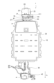
- FIG. 1 is an explanatory diagram of a drive unit according to an embodiment of the invention.
- FIG. 2 is an explanatory diagram of an electric vehicle on which the drive unit is mounted.
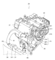
- FIG. 3 is an explanatory diagram of the drive unit.
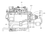
- FIG. 4 is an explanatory diagram of the drive unit.
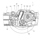
- FIG. 5 is a cross-sectional view of the electric vehicle.
- FIG. 1 is an explanatory diagram of the rear drive unit 20 of this embodiment.
- FIG. 2 is an explanatory diagram of the entire drive system of the electric vehicle 1 in which the rear drive unit 20 according to the embodiment of the invention is mounted.
- An electric vehicle 1 (hereinafter referred to as vehicle 1) is configured by mounting a rear drive unit 20, a battery unit 30, and a front drive unit 40 on a vehicle body 10, as shown in FIG.
- the rear drive unit 20 is arranged behind the battery unit 30 in the vehicle.
- a wire harness 35 for supplying DC power from the battery unit 30 is connected to the rear drive unit 20 .
- the rear drive unit 20 is configured with an inverter device 21, a drive motor 22 and a speed reducer 23.
- a cooling water pipe 26 through which cooling water flows is connected to the rear drive unit 20 .
- the rear drive unit 20 drives the vehicle 1 by driving the drive motor 22 based on the electric power from the battery unit 30, thereby rotating the axle 23a and the rear wheels 15 (see FIG. 5) that are drive wheels. .
- a drive motor 22 and a speed reducer 23 are arranged in the vehicle width direction with their rotation shafts parallel to each other.
- the inverter device 21 is arranged above the drive motor 22 and the speed reducer 23 so as to be inclined toward the front side of the vehicle 1 .
- the inverter device 21 includes an inverter (not shown) that converts electric power supplied from the battery unit 30 into electric power suitable for driving the drive motor 22 and supplies the electric power to the drive motor 22 .
- the inverter is accommodated in a housing 24 that is a metal or resin enclosure.
- the inverter device 21 receives power supply from the battery unit 30 to drive the drive motor 22 . Further, the inverter device 21 receives regenerated electric power from the drive motor 22 and charges the battery unit 30 .
- the drive motor 22 is composed of a rotating electric machine such as a permanent magnet embedded synchronous motor or a field winding synchronous motor.
- the speed reducer 23 is configured with a plurality of gears that reduce the speed of rotation of the drive motor 22 and transmit it to the axle.
- the speed reducer 23 may be configured as a transmission capable of stepwise or steplessly switching a plurality of gear stages.
- the battery unit 30 is arranged on the floor between the front and rear wheels of the vehicle 1, as shown in FIG.
- the battery unit 30 is configured with a plurality of battery modules inside.
- a wire harness 35 for supplying electric power is connected to the inverter device 21 and the battery unit 30 .
- the wire harness 35 is composed of a pair of positive and negative conductor wires, which are made of copper, aluminum, or the like and are coated with insulation.
- the wire harness 35 is covered with a protector 60 and a cushioning material 61 .
- the wire harness 35 has terminals connected to the inverter device 21 and the battery unit 30 at both ends thereof. .
- a front drive unit 40 that drives the front wheels is provided on the front side (motor room) of the vehicle 1, as shown in FIG.
- the front drive unit 40 includes a front drive motor (not shown) and a front inverter device 41 that supplies power to the front drive motor.
- a front wire harness 36 for supplying electric power is connected between the front inverter device 41 of the front drive unit 40 and the battery unit 30 .
- vehicle 1 of this embodiment does not necessarily have to include the front drive unit 40 .
- vehicle 1 may be configured such that only the rear wheels 15 are driven by the rear drive unit 20 .
- the rear drive unit 20 arranged on the rear side of the vehicle has the battery unit 30 arranged on the front side thereof, and the structure of the vehicle body 10 such as the luggage compartment exists on the upper side thereof. height is lower. Due to this structure, the space between the rear drive unit 20 and the battery unit 30 does not have enough margin. Furthermore, since the wire harness is composed of thick wires so that the voltage of the battery unit 30 (for example, 400 V DC) can flow, the degree of freedom in bending and elasticity are low. For this reason, conventionally, there has been a problem that it is difficult to give the wire harness a sufficient length.
- the wire harness 35 is configured to have a marginal length to address such a problem.
- one end of the wire harness 35 is connected to an inverter-side connector 211 provided on the side surface of the inverter device 21 , and the other end is arranged so as to protrude from the rear end side of the battery unit 30 . It is connected to a battery side connector 311 provided in the connecting portion 31 connected to the battery.
- One end of the wire harness 35 is configured as the one end side connection terminal P1, and the other end is configured as the other end side connection terminal P2.
- the housing 24 of the inverter device 21 is provided with an opening 241 to which the one-end connection terminal P1, which will be described in detail in FIG. 3, is fixed, and a cover 242 that closes the opening.
- the inverter-side connector 211 is provided on the left side of the inverter device 21 in the vehicle front-rear direction, and is connected to one end-side connection terminal P1 of the wire harness 35 .
- the battery-side connector 311 is provided on the right side in the vehicle front-rear direction of the connecting portion 31 projecting from the rear end side of the battery unit 30 .
- the other end side connection terminal P2 of the wire harness 35 is connected to the battery side connector 311 .
- the wire harness 35 extends in the vehicle width direction from the inverter-side connector 211 on the left side surface of the inverter device 21, and then bends 180 degrees toward the right side in the vehicle width direction.
- the wire harness 35 is routed from the left side to the right side in the vehicle width direction between the inverter device 21 and the battery unit 30, and is turned 180° toward the left side in the vehicle width direction near the right side surface of the inverter device 21. flex.
- the wire harness 35 extends to a battery-side connector 311 arranged on the right side surface of the connection portion 31 of the battery unit 30 .
- one end of the wire harness 35 is connected to the inverter side connector 211 provided on the left side surface of the inverter device 21 from the left side to the right side (first direction) in the vehicle width direction, and the other end is connected to the battery unit. It is connected to the battery side connector 311 provided on the right side surface of the connecting portion 31 of 30 from the right side toward the left side (second direction) in the vehicle width direction.
- the wire harness 35 is routed in the vehicle width direction, and is formed in an S shape (Z shape) bent at about 180° when viewed from above.
- one end of the wire harness 36 is connected to a connector provided on the left side surface of the front inverter device 41 from left to right (second direction) in the vehicle width direction. be done.
- the wire harness 35 is covered with a U-shaped hard resin protector 60 near the inverter-side connector 211 so as to cover the outer periphery thereof.
- the protector 60 is supported by the housing 24 of the inverter device 21 with a predetermined distance from the inverter device 21 by means of an L-shaped bracket 65 .
- the bracket 65 has a housing fixing portion that is fixed to the surface of the housing 24 by bolting, and a protector fixing portion that extends toward the protector 60 and is fixed to the rear surface of the protector 60 by bolting.
- the housing fixing portion and the protector fixing portion are formed in a crank shape in the vehicle front-rear direction.
- a buffer material 61 made of soft resin is wrapped around the battery-side connector 311 of the wire harness 35 .
- the wire harness 35 is restricted from swinging near the inverter device 21 by the protector 60 and the bracket 65 while maintaining a predetermined distance from the inverter device 21 .
- stress due to excessive vibration of the wire harness 35 is suppressed, and the durability of the wire harness 35 is improved.
- the soft cushioning material 61 allows the wire harness 35 to swing, and suppresses the wire harness 35 from buffering with other members.
- the wire harness 35 can have a margin in the vehicle width direction while arranging the rear drive unit 20 closer to the battery unit 30 .
- the wire harness 35 is configured to be able to swing, the relative swing between the rear drive unit 20 and the vehicle body 10 to which the battery unit 30 is fixed is allowed, and is applied to the wire harness 35. Can relieve stress.
- FIG. 3 and 4 are explanatory diagrams of the inverter device 21 of this embodiment, and are diagrams for explaining the inverter-side connector 211.
- FIG. 3 shows a perspective view of the inverter device 21
- FIG. 4 shows a front view of the inverter device 21 as viewed from the front side of the vehicle.
- 3 and 4 both show a state in which the protector 60 of the wire harness 35 and the cover 242 of the inverter-side connector 211 are removed. Also, the speed reducer 23 is omitted.
- An insertion hole 215 into which the one-end connection terminal P1 is inserted is formed on the side surface of the inverter device 21 .
- An opening 241 is formed on the front side of the inverter device 21 for bolting with the one-end-side connection terminal P1 inserted therein.
- a terminal (not shown) is provided inside the opening 241, and the one end side connection terminal P1 is fixed to this terminal.
- a plate-shaped positive electrode terminal BP1 connected to the positive electrode side conductor wire and a plate-shaped negative electrode terminal BN1 fixed to the negative electrode side conductor wire are provided.
- Each terminal is formed with a bolt hole for fixing a bolt.
- a boot 214 fixed to the insertion hole 215 is provided on the one end side connection terminal P ⁇ b>1 of the wire harness 35 .
- the inverter-side connector 211 and the one-end-side connection terminal P1 configured in this way are assembled as follows. First, the positive terminal BP1 and the negative terminal BN1 constituting the one end side connection terminal P1 of the wire harness 35 are inserted through the insertion hole 215 opened in the side surface of the housing 24 . The positive terminal BP1 and the negative terminal BN1 are fixed to terminals on the inverter device 21 side through the opening 241 by bolting. After the positive terminal BP1 and the negative terminal BN1 are fixed, the opening 241 is closed by the cover 242 . A boot 214 attached to one end of the wire harness 35 is fixed to the insertion hole 215 by bolting.
- the one-end connection terminal P1 is fixed to the inverter-side connector 211.
- the other end side of the wire harness 35 is constituted by the other end side connection terminal P2, which is a one-touch connector that can be inserted into and removed from the connection portion 31 of the battery unit 30, as shown in FIG.
- the other end side connection terminal P2 is locked by being inserted into the battery side connector 311 .
- the operator when removing the rear drive unit 20 from the vehicle body 10 during maintenance of the vehicle 1, first, the operator removes the other end side connection terminal P2 from the battery side connector 311 on the battery unit 30 side. Since the other end side connection terminal P2 is a one-touch connector, it can be easily attached and detached by a predetermined procedure. The rear drive unit 20 is removed from the vehicle body 10 with the wire harness 35 connected.
- FIG. 5 is a vertical cross-sectional view of the vehicle 1 in the front-rear direction centering on the rear drive unit 20 of this embodiment.
- the rear drive unit 20 is arranged under the floor on the rear side of the vehicle body 10 via a suspension member 102 fixed to the vehicle body 10 .
- a cross member 101 is arranged on the vehicle body 10 so as to traverse the vehicle body 10 in the width direction.
- the rear drive unit 20 is arranged adjacent to the cross member 101 on the rear side of the cross member 101 .
- Battery unit 30 is fixed to the underfloor portion of vehicle body 10 on the front side of cross member 101 .
- the wire harness 35 described above is routed between the rear drive unit 20 and the battery unit 30 .
- a protector 60 is attached to the wiring harness 35 near the inverter device 21 .
- Protector 60 is fixed to the outside of housing 24 of inverter device 21 by bracket 65 .
- the wire harness 35 may be caught between the housing 24 of the inverter device 21 and the cross member 101 .
- the fixing positions of the bracket 65 for fixing the protector 60 that is, the housing fixing portion fixed to the housing 24 and the protector fixing portion fixed to the protector 60 are arranged at a height above the ground of the cross member 101. (the bottom surface of the cross member 101 indicated by the dashed line in FIG. 5).
- the vehicle 1 includes the drive unit (rear drive unit 20) and the battery unit 30 that supplies power to the rear drive unit 20 via the wire harness 35.
- the battery unit 30 is arranged on the floor surface between the front wheels and the rear wheels of the vehicle 1
- the rear drive unit 20 is arranged on the rear side of the vehicle 1 relative to the battery unit 30 .
- the rear drive unit 20 includes a drive motor 22 that drives the rear wheels 15 that are drive wheels, and an inverter device 21 that converts the power of the battery unit 30 and supplies the converted power to the drive motor 22 .
- One end of the wire harness 35 is connected to the inverter device 21 in the vehicle width direction at the side portion of the inverter device 21, and the other end is connected to the battery unit 30 in the vehicle width direction at the rear end portion of the battery unit 30. be done.
- the wire harness 35 is connected to the inverter device 21 and the battery unit 30 in the vehicle width direction.
- the wire harness 35 can be routed in the lateral direction of the vehicle 1 .
- the harness length of the wire harness 35 between the inverter device 21 and the battery unit 30 can have a margin in the lateral direction, the stress applied to the wire harness 35 when the rear drive unit 20 swings. can be mitigated.
- one end of the wire harness 35 is connected to the inverter device 21 from the left side to the right side (first direction) in the vehicle width direction via the inverter side connector 211, and the other end is connected to the battery side. It is connected to the battery unit 30 via the connector 311 from the right side to the left side (second direction) in the vehicle width direction opposite to the first direction.
- the wire harness 35 is routed while being bent in an S shape between the first direction and the second direction. can be routed in the lateral direction, and the harness length of the wire harness 35 can be given a margin.
- the inverter-side connector 211 fixes the wire harness 35 to the inverter device 21 by bolting
- the battery-side connector 311 is configured by a detachable one-touch connector.
- the rear drive unit 20 can be removed from the vehicle body 10 together with the wire harness 35 by removing the battery-side connector 311 that is easily attached and detached during maintenance.
- the front side of the vehicle 1 is provided with a front drive unit 40 having a front inverter device 41 and a front wire harness 36 that supplies electric power from the battery unit 30 to the front inverter device 41 .
- the front wire harness 36 has one end connected to the battery unit 30 and the other end connected to the front inverter device 41 from left to right (first direction) in the vehicle width direction.
- the inverter device 21 arranged on the rear wheel side and the front inverter device 41 on the front wheel side are connected to the wire harnesses 35 and 36 from the same first direction, they are arranged on the rear side.
- the inverter device 21 and the front inverter device 41 can have the same connectors and internal configurations. This eliminates the need to use different parts for the inverter device 21 and the front inverter device 41, thereby reducing the manufacturing cost.
- the wire harness 35 is fitted with a protector 60 that restricts rocking near one end thereof, that is, near the inverter-side connector 211 of the inverter device 21 .
- the soft cushioning material 61 prevents the wire harness 35 from buffering with other members while allowing rocking motion.
- the rear drive unit 20 is provided behind the cross member 101 adjacent to the cross member 101 that crosses the underfloor of the vehicle 1 in the vehicle width direction, and the protector 60 is connected to the inverter by the bracket 65 . It is fixed to the housing 24 of the device 21 , and the fixing position between the bracket 65 and the housing 24 is between the cross member 101 and the inverter device 21 and below the cross member 101 .
Landscapes
- Engineering & Computer Science (AREA)
- Mechanical Engineering (AREA)
- Transportation (AREA)
- Power Engineering (AREA)
- Life Sciences & Earth Sciences (AREA)
- Sustainable Development (AREA)
- Sustainable Energy (AREA)
- Chemical & Material Sciences (AREA)
- Combustion & Propulsion (AREA)
- Arrangement Or Mounting Of Propulsion Units For Vehicles (AREA)
Abstract
Description
Claims (6)
- 車両を駆動する駆動ユニットと、ワイヤハーネスを介して前記駆動ユニットに電力を供給するバッテリユニットと、を備える車両における、ワイヤハーネスの取付構造であって、
前記バッテリユニットは、前記車両の前輪と後輪との間の床面に配置され、
前記駆動ユニットは、前記バッテリユニットよりも前記車両の後側に配置されて、駆動輪を駆動する駆動モータと、前記バッテリユニットの電力を変換して前記駆動モータに供給するインバータ装置と、を備え、
前記ワイヤハーネスは、
その一端が、前記インバータ装置の側面部で、車幅方向から前記インバータ装置に連結され、
その他端が、前記バッテリユニットの後端部で、車幅方向から前記バッテリユニットに連結される、
ワイヤハーネスの取付構造。 - 請求項1に記載のワイヤハーネスの取付構造であって、
前記一端は、インバータ側コネクタを介して、車幅方向の第一方向から前記インバータ装置に連結され、
前記他端は、バッテリ側コネクタを介して、前記第一方向とは逆側の第二方向からバッテリユニットに連結される、
ワイヤハーネスの取付構造。 - 請求項2に記載のワイヤハーネスの取付構造であって、
前記インバータ側コネクタは、前記ワイヤハーネスをボルト止めにより前記インバータ装置に固定され、
前記バッテリ側コネクタは、着脱可能なワンタッチコネクタにより構成される、
ワイヤハーネスの取付構造。 - 請求項2又は3に記載のワイヤハーネスの取付構造であって、
前記車両の前側には、前側インバータ装置を備える前側駆動ユニットと、前記バッテリユニットの電力を前記前側インバータ装置に供給する前側ワイヤハーネスと、が備えられ、
前記前側ワイヤハーネスは、その一端が前記バッテリユニットに連結され、その他端が前記前側インバータ装置に前記第二方向から連結される、
ワイヤハーネスの取付構造。 - 請求項1から4のいずれか一つに記載のワイヤハーネスの取付構造であって、
前記ワイヤハーネスは、その一端付近で、揺動を規制するプロテクタが外装される、
ワイヤハーネスの取付構造。 - 請求項5に記載のワイヤハーネスの取付構造であって、
前記駆動ユニットは、前記車両の床下を車幅方向に横断するクロスメンバに隣接して、前記クロスメンバの後方に備えられ、
前記プロテクタは、ブラケットにより前記インバータ装置のハウジングに固定され、
前記ブラケットと前記ハウジングとの固定位置が、前記クロスメンバと前記インバータ装置との間であって、前記クロスメンバよりも下方に位置する、
ワイヤハーネスの取付構造。
Priority Applications (6)
| Application Number | Priority Date | Filing Date | Title |
|---|---|---|---|
| EP22922550.3A EP4470841A4 (en) | 2022-01-26 | 2022-01-26 | CABLE HARNESS FIXING STRUCTURE |
| CN202280089816.9A CN118591469A (zh) | 2022-01-26 | 2022-01-26 | 配线束的安装构造 |
| JP2023576457A JP7662063B2 (ja) | 2022-01-26 | 2022-01-26 | ワイヤハーネスの取付構造 |
| US18/833,161 US12403850B2 (en) | 2022-01-26 | 2022-01-26 | Wire harness mounting structure |
| PCT/JP2022/002897 WO2023144930A1 (ja) | 2022-01-26 | 2022-01-26 | ワイヤハーネスの取付構造 |
| MX2024009138A MX2024009138A (es) | 2022-01-26 | 2022-01-26 | Estructura de montaje de arnes de cables. |
Applications Claiming Priority (1)
| Application Number | Priority Date | Filing Date | Title |
|---|---|---|---|
| PCT/JP2022/002897 WO2023144930A1 (ja) | 2022-01-26 | 2022-01-26 | ワイヤハーネスの取付構造 |
Publications (1)
| Publication Number | Publication Date |
|---|---|
| WO2023144930A1 true WO2023144930A1 (ja) | 2023-08-03 |
Family
ID=87471198
Family Applications (1)
| Application Number | Title | Priority Date | Filing Date |
|---|---|---|---|
| PCT/JP2022/002897 Ceased WO2023144930A1 (ja) | 2022-01-26 | 2022-01-26 | ワイヤハーネスの取付構造 |
Country Status (6)
| Country | Link |
|---|---|
| US (1) | US12403850B2 (ja) |
| EP (1) | EP4470841A4 (ja) |
| JP (1) | JP7662063B2 (ja) |
| CN (1) | CN118591469A (ja) |
| MX (1) | MX2024009138A (ja) |
| WO (1) | WO2023144930A1 (ja) |
Cited By (2)
| Publication number | Priority date | Publication date | Assignee | Title |
|---|---|---|---|---|
| WO2025191851A1 (ja) * | 2024-03-15 | 2025-09-18 | 日産自動車株式会社 | 電動パワーステアリング装置 |
| WO2026017932A1 (fr) | 2024-07-19 | 2026-01-22 | Stellantis Auto Sas | Vehicule automobile avec boucle dynamique de faisceau de cables de porte-moyeu de roue protegee |
Citations (6)
| Publication number | Priority date | Publication date | Assignee | Title |
|---|---|---|---|---|
| JP2009286287A (ja) * | 2008-05-29 | 2009-12-10 | Toyota Motor Corp | 取り付け構造 |
| JP5589772B2 (ja) | 2010-10-29 | 2014-09-17 | マツダ株式会社 | 電動車両の電装部品搭載構造 |
| JP2016159816A (ja) * | 2015-03-03 | 2016-09-05 | 日産自動車株式会社 | 電動車両のハーネス接続構造 |
| JP2017140991A (ja) * | 2016-02-12 | 2017-08-17 | 本田技研工業株式会社 | 車両 |
| JP2020104558A (ja) * | 2018-12-26 | 2020-07-09 | 株式会社オートネットワーク技術研究所 | ワイヤハーネス配索部材 |
| JP2020189594A (ja) * | 2019-05-23 | 2020-11-26 | 本田技研工業株式会社 | 車両 |
Family Cites Families (6)
| Publication number | Priority date | Publication date | Assignee | Title |
|---|---|---|---|---|
| JP5360689B2 (ja) * | 2009-09-24 | 2013-12-04 | スズキ株式会社 | 車両の高電圧ケーブルの配策構造 |
| US8899360B2 (en) * | 2010-11-12 | 2014-12-02 | Honda Motor Co., Ltd. | Cable arrangement structure for vehicle |
| JP5776852B2 (ja) * | 2012-08-27 | 2015-09-09 | 日産自動車株式会社 | 電動車両の強電ハーネス接続構造 |
| JP6718935B2 (ja) * | 2018-09-12 | 2020-07-08 | 本田技研工業株式会社 | 車両 |
| JP7276687B2 (ja) * | 2019-08-22 | 2023-05-18 | マツダ株式会社 | 車両前部構造 |
| JP2021184326A (ja) | 2020-05-21 | 2021-12-02 | ダイムラー・アクチェンゲゼルシャフトDaimler AG | バッテリパック、バッテリユニット、及び電動車両 |
-
2022
- 2022-01-26 JP JP2023576457A patent/JP7662063B2/ja active Active
- 2022-01-26 US US18/833,161 patent/US12403850B2/en active Active
- 2022-01-26 CN CN202280089816.9A patent/CN118591469A/zh active Pending
- 2022-01-26 MX MX2024009138A patent/MX2024009138A/es unknown
- 2022-01-26 WO PCT/JP2022/002897 patent/WO2023144930A1/ja not_active Ceased
- 2022-01-26 EP EP22922550.3A patent/EP4470841A4/en active Pending
Patent Citations (6)
| Publication number | Priority date | Publication date | Assignee | Title |
|---|---|---|---|---|
| JP2009286287A (ja) * | 2008-05-29 | 2009-12-10 | Toyota Motor Corp | 取り付け構造 |
| JP5589772B2 (ja) | 2010-10-29 | 2014-09-17 | マツダ株式会社 | 電動車両の電装部品搭載構造 |
| JP2016159816A (ja) * | 2015-03-03 | 2016-09-05 | 日産自動車株式会社 | 電動車両のハーネス接続構造 |
| JP2017140991A (ja) * | 2016-02-12 | 2017-08-17 | 本田技研工業株式会社 | 車両 |
| JP2020104558A (ja) * | 2018-12-26 | 2020-07-09 | 株式会社オートネットワーク技術研究所 | ワイヤハーネス配索部材 |
| JP2020189594A (ja) * | 2019-05-23 | 2020-11-26 | 本田技研工業株式会社 | 車両 |
Non-Patent Citations (1)
| Title |
|---|
| See also references of EP4470841A4 |
Cited By (3)
| Publication number | Priority date | Publication date | Assignee | Title |
|---|---|---|---|---|
| WO2025191851A1 (ja) * | 2024-03-15 | 2025-09-18 | 日産自動車株式会社 | 電動パワーステアリング装置 |
| WO2026017932A1 (fr) | 2024-07-19 | 2026-01-22 | Stellantis Auto Sas | Vehicule automobile avec boucle dynamique de faisceau de cables de porte-moyeu de roue protegee |
| FR3164690A1 (fr) | 2024-07-19 | 2026-01-23 | Stellantis Auto Sas | Vehicule automobile avec boucle dynamique de faisceau de cables de porte-moyeu de roue protegee |
Also Published As
| Publication number | Publication date |
|---|---|
| CN118591469A (zh) | 2024-09-03 |
| MX2024009138A (es) | 2024-08-06 |
| EP4470841A4 (en) | 2025-07-02 |
| US20250108769A1 (en) | 2025-04-03 |
| US12403850B2 (en) | 2025-09-02 |
| JP7662063B2 (ja) | 2025-04-15 |
| EP4470841A1 (en) | 2024-12-04 |
| JPWO2023144930A1 (ja) | 2023-08-03 |
Similar Documents
| Publication | Publication Date | Title |
|---|---|---|
| US11492044B2 (en) | Vehicle front structure | |
| US8479867B2 (en) | Vehicle drive unit | |
| JP3815456B2 (ja) | ハイブリッド車両における高圧電線の配策構造 | |
| JP5589772B2 (ja) | 電動車両の電装部品搭載構造 | |
| CN102673492B (zh) | 车辆中的高压电缆的布线结构 | |
| US9827923B2 (en) | Harness routing structure for electric vehicle | |
| JP6256234B2 (ja) | 電動車両 | |
| JP6688851B2 (ja) | 車両 | |
| WO2023144930A1 (ja) | ワイヤハーネスの取付構造 | |
| JP2021109478A (ja) | 電気機器の車載構造 | |
| JP5958050B2 (ja) | 電動車両のパワーユニット支持装置 | |
| CN103101421A (zh) | 车辆 | |
| JP7091299B2 (ja) | 車両用駆動ユニット | |
| JP2023136720A (ja) | 電動車両の駆動装置 | |
| CN111661166B (zh) | 车辆前部结构 | |
| CN115052775B (zh) | 混合动力系统 | |
| CN121311388A (zh) | 线束的安装结构 | |
| JP7272133B2 (ja) | 車両のケーブル取付構造 | |
| JP7234824B2 (ja) | モータ駆動装置の設置構造 | |
| JP7210986B2 (ja) | 車両のケーブル配索構造 | |
| JP2025152450A (ja) | 車両のパワートレイン構造 | |
| JP2024112732A (ja) | 車両用駆動装置 | |
| JP2025152451A (ja) | 車両のパワートレイン構造 | |
| JP2013248976A (ja) | 車両のハーネス支持構造 |
Legal Events
| Date | Code | Title | Description |
|---|---|---|---|
| 121 | Ep: the epo has been informed by wipo that ep was designated in this application |
Ref document number: 22922550 Country of ref document: EP Kind code of ref document: A1 |
|
| WWE | Wipo information: entry into national phase |
Ref document number: 202280089816.9 Country of ref document: CN Ref document number: MX/A/2024/009138 Country of ref document: MX |
|
| WWE | Wipo information: entry into national phase |
Ref document number: 2401004784 Country of ref document: TH |
|
| ENP | Entry into the national phase |
Ref document number: 2023576457 Country of ref document: JP Kind code of ref document: A |
|
| WWE | Wipo information: entry into national phase |
Ref document number: 18833161 Country of ref document: US |
|
| REG | Reference to national code |
Ref country code: BR Ref legal event code: B01A Ref document number: 112024015325 Country of ref document: BR |
|
| NENP | Non-entry into the national phase |
Ref country code: DE |
|
| ENP | Entry into the national phase |
Ref document number: 2022922550 Country of ref document: EP Effective date: 20240826 |
|
| ENP | Entry into the national phase |
Ref document number: 112024015325 Country of ref document: BR Kind code of ref document: A2 Effective date: 20240725 |
|
| WWP | Wipo information: published in national office |
Ref document number: 18833161 Country of ref document: US |
|
| WWG | Wipo information: grant in national office |
Ref document number: 18833161 Country of ref document: US |