WO2023145174A1 - 搬送装置、および搬送方法 - Google Patents
搬送装置、および搬送方法 Download PDFInfo
- Publication number
- WO2023145174A1 WO2023145174A1 PCT/JP2022/040475 JP2022040475W WO2023145174A1 WO 2023145174 A1 WO2023145174 A1 WO 2023145174A1 JP 2022040475 W JP2022040475 W JP 2022040475W WO 2023145174 A1 WO2023145174 A1 WO 2023145174A1
- Authority
- WO
- WIPO (PCT)
- Prior art keywords
- conveying
- coil
- speed
- envelope
- winding
- Prior art date
- Legal status (The legal status is an assumption and is not a legal conclusion. Google has not performed a legal analysis and makes no representation as to the accuracy of the status listed.)
- Ceased
Links
Images


Classifications
-
- H—ELECTRICITY
- H02—GENERATION; CONVERSION OR DISTRIBUTION OF ELECTRIC POWER
- H02P—CONTROL OR REGULATION OF ELECTRIC MOTORS, ELECTRIC GENERATORS OR DYNAMO-ELECTRIC CONVERTERS; CONTROLLING TRANSFORMERS, REACTORS OR CHOKE COILS
- H02P6/00—Arrangements for controlling synchronous motors or other dynamo-electric motors using electronic commutation dependent on the rotor position; Electronic commutators therefor
- H02P6/14—Electronic commutators
- H02P6/16—Circuit arrangements for detecting position
- H02P6/17—Circuit arrangements for detecting position and for generating speed information
-
- B—PERFORMING OPERATIONS; TRANSPORTING
- B65—CONVEYING; PACKING; STORING; HANDLING THIN OR FILAMENTARY MATERIAL
- B65G—TRANSPORT OR STORAGE DEVICES, e.g. CONVEYORS FOR LOADING OR TIPPING, SHOP CONVEYOR SYSTEMS OR PNEUMATIC TUBE CONVEYORS
- B65G54/00—Non-mechanical conveyors not otherwise provided for
- B65G54/02—Non-mechanical conveyors not otherwise provided for electrostatic, electric, or magnetic
-
- G—PHYSICS
- G01—MEASURING; TESTING
- G01N—INVESTIGATING OR ANALYSING MATERIALS BY DETERMINING THEIR CHEMICAL OR PHYSICAL PROPERTIES
- G01N35/00—Automatic analysis not limited to methods or materials provided for in any single one of groups G01N1/00 - G01N33/00; Handling materials therefor
- G01N35/02—Automatic analysis not limited to methods or materials provided for in any single one of groups G01N1/00 - G01N33/00; Handling materials therefor using a plurality of sample containers moved by a conveyor system past one or more treatment or analysis stations
- G01N35/04—Details of the conveyor system
-
- G—PHYSICS
- G01—MEASURING; TESTING
- G01P—MEASURING LINEAR OR ANGULAR SPEED, ACCELERATION, DECELERATION, OR SHOCK; INDICATING PRESENCE, ABSENCE, OR DIRECTION, OF MOVEMENT
- G01P3/00—Measuring linear or angular speed; Measuring differences of linear or angular speeds
- G01P3/42—Devices characterised by the use of electric or magnetic means
- G01P3/50—Devices characterised by the use of electric or magnetic means for measuring linear speed
- G01P3/52—Devices characterised by the use of electric or magnetic means for measuring linear speed by measuring amplitude of generated current or voltage
-
- H—ELECTRICITY
- H02—GENERATION; CONVERSION OR DISTRIBUTION OF ELECTRIC POWER
- H02P—CONTROL OR REGULATION OF ELECTRIC MOTORS, ELECTRIC GENERATORS OR DYNAMO-ELECTRIC CONVERTERS; CONTROLLING TRANSFORMERS, REACTORS OR CHOKE COILS
- H02P25/00—Arrangements or methods for the control of AC motors characterised by the kind of AC motor or by structural details
- H02P25/02—Arrangements or methods for the control of AC motors characterised by the kind of AC motor or by structural details characterised by the kind of motor
- H02P25/06—Linear motors
- H02P25/064—Linear motors of the synchronous type
-
- H—ELECTRICITY
- H02—GENERATION; CONVERSION OR DISTRIBUTION OF ELECTRIC POWER
- H02P—CONTROL OR REGULATION OF ELECTRIC MOTORS, ELECTRIC GENERATORS OR DYNAMO-ELECTRIC CONVERTERS; CONTROLLING TRANSFORMERS, REACTORS OR CHOKE COILS
- H02P6/00—Arrangements for controlling synchronous motors or other dynamo-electric motors using electronic commutation dependent on the rotor position; Electronic commutators therefor
- H02P6/006—Controlling linear motors
-
- H—ELECTRICITY
- H02—GENERATION; CONVERSION OR DISTRIBUTION OF ELECTRIC POWER
- H02P—CONTROL OR REGULATION OF ELECTRIC MOTORS, ELECTRIC GENERATORS OR DYNAMO-ELECTRIC CONVERTERS; CONTROLLING TRANSFORMERS, REACTORS OR CHOKE COILS
- H02P6/00—Arrangements for controlling synchronous motors or other dynamo-electric motors using electronic commutation dependent on the rotor position; Electronic commutators therefor
- H02P6/14—Electronic commutators
- H02P6/16—Circuit arrangements for detecting position
- H02P6/18—Circuit arrangements for detecting position without separate position detecting elements
- H02P6/185—Circuit arrangements for detecting position without separate position detecting elements using inductance sensing, e.g. pulse excitation
-
- B—PERFORMING OPERATIONS; TRANSPORTING
- B65—CONVEYING; PACKING; STORING; HANDLING THIN OR FILAMENTARY MATERIAL
- B65G—TRANSPORT OR STORAGE DEVICES, e.g. CONVEYORS FOR LOADING OR TIPPING, SHOP CONVEYOR SYSTEMS OR PNEUMATIC TUBE CONVEYORS
- B65G2201/00—Indexing codes relating to handling devices, e.g. conveyors, characterised by the type of product or load being conveyed or handled
- B65G2201/02—Articles
- B65G2201/0235—Containers
- B65G2201/0261—Puck as article support
-
- B—PERFORMING OPERATIONS; TRANSPORTING
- B65—CONVEYING; PACKING; STORING; HANDLING THIN OR FILAMENTARY MATERIAL
- B65G—TRANSPORT OR STORAGE DEVICES, e.g. CONVEYORS FOR LOADING OR TIPPING, SHOP CONVEYOR SYSTEMS OR PNEUMATIC TUBE CONVEYORS
- B65G2203/00—Indexing code relating to control or detection of the articles or the load carriers during conveying
- B65G2203/02—Control or detection
- B65G2203/0208—Control or detection relating to the transported articles
- B65G2203/025—Speed of the article
-
- G—PHYSICS
- G01—MEASURING; TESTING
- G01N—INVESTIGATING OR ANALYSING MATERIALS BY DETERMINING THEIR CHEMICAL OR PHYSICAL PROPERTIES
- G01N35/00—Automatic analysis not limited to methods or materials provided for in any single one of groups G01N1/00 - G01N33/00; Handling materials therefor
- G01N35/02—Automatic analysis not limited to methods or materials provided for in any single one of groups G01N1/00 - G01N33/00; Handling materials therefor using a plurality of sample containers moved by a conveyor system past one or more treatment or analysis stations
- G01N35/04—Details of the conveyor system
- G01N2035/0401—Sample carriers, cuvettes or reaction vessels
- G01N2035/0406—Individual bottles or tubes
-
- G—PHYSICS
- G01—MEASURING; TESTING
- G01N—INVESTIGATING OR ANALYSING MATERIALS BY DETERMINING THEIR CHEMICAL OR PHYSICAL PROPERTIES
- G01N35/00—Automatic analysis not limited to methods or materials provided for in any single one of groups G01N1/00 - G01N33/00; Handling materials therefor
- G01N35/02—Automatic analysis not limited to methods or materials provided for in any single one of groups G01N1/00 - G01N33/00; Handling materials therefor using a plurality of sample containers moved by a conveyor system past one or more treatment or analysis stations
- G01N35/04—Details of the conveyor system
- G01N2035/0474—Details of actuating means for conveyors or pipettes
- G01N2035/0477—Magnetic
Definitions
- the present invention relates to a conveying device and a conveying method.
- Patent Document 1 discloses a conveying container having a magnetic material mounted thereon.
- a conveying plane for conveying, a position detecting section for detecting the position of the conveying container on the conveying plane, a magnetic pole arranged below the conveying plane and having a core and a coil, a driving section for applying a voltage to the magnetic pole, a calculating unit for controlling the driving unit, the calculating unit calculating the conveying speed of the conveying container based on the position of the conveying container on the conveying plane and the time at which the conveying container passes the position; It is described that the surface condition of the conveying plane is detected based on the conveying speed of .
- sample analysis system for clinical tests performs tests for specified analysis items on samples (samples) such as blood, plasma, serum, urine, and other body fluids.
- This sample analysis system connects devices with multiple functions and automatically executes each process.
- the analysis part analysis process
- the pretreatment part pretreatment process
- One of the methods for transporting such specimens is an electromagnetic transport system using an electromagnetic actuator.
- Patent Document 1 As an example of a method for estimating the speed of a conveyed object in a conveying apparatus using such an electromagnetic actuator, there is a technique described in Patent Document 1.
- Patent Document 1 the conveying speed is obtained based on the positions of the two detected points, the positions, and the time at which the positions are passed.
- it is necessary to detect the position at a plurality of positions in order to calculate the transport speed. There is room for improvement because there is concern that the detection accuracy of the conveying speed will be affected.
- An object of the present invention is to provide a conveying device and a conveying method that are capable of detecting the speed of conveyed objects with higher accuracy than in the past.
- the present invention includes a plurality of means for solving the above-mentioned problems, and to give an example, an electromagnet including a core and windings, a detection section for detecting the current flowing through the windings of the electromagnet, A driving unit that supplies a voltage to the electromagnet and a control unit, wherein the control unit adjusts the transportation speed of the transportation container provided with the magnetic material to the current flowing through one of the windings under the influence of electromagnetic induction. characterized by estimating based on
- the speed of conveyed objects can be detected with higher accuracy than in the past.
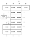
- FIG. 2 is a plan view showing the configuration of the entire sample analysis system including the transport device according to Example 1.
- FIG. 1 is a top view showing an example of a configuration of a conveying device according to Embodiment 1;
- FIG. FIG. 4 is a diagram schematically showing a difference depending on the magnitude of the inductance between the applied voltage waveform and the corresponding current waveform in the conveying apparatus according to the first embodiment; 4 is a diagram showing the relationship between the current flowing through the coil detected by the current detection unit and the distance between the holder and the coil in the conveying apparatus according to Example 1.
- FIG. 5 is a diagram showing the relationship between the speed of an object to be conveyed and the minimum value of the current flowing through the coil at that conveying speed in the conveying apparatus according to the first embodiment
- 4 is a waveform diagram showing an example of the relationship between a current waveform flowing through a coil when a pulse voltage is applied, an envelope waveform thereof, and a distance between the coil and the holder in the conveying apparatus according to Example 1.
- FIG. 4 is a waveform diagram showing an example of the relationship between a current waveform flowing through a coil when a pulse voltage is applied, an envelope waveform thereof, and a distance between the coil and the holder in the conveying apparatus according to Example 1.
- FIG. 4 is a waveform diagram showing an example of the relationship between a current waveform flowing through a coil when a pulse voltage is applied, an envelope waveform thereof, and a distance between the coil and the holder in the conveying apparatus according to Example 1.
- FIG. 6 is a flowchart for explaining the flow of processing for estimating the speed of a conveyed object in the conveying apparatus according to the first embodiment
- FIG. 10 is a diagram showing the relationship between the differentiated waveform of the current flowing through the coil detected by the current detection unit and the distance between the holder and the coil in the conveying apparatus according to the second embodiment;
- FIG. 1 is a plan view showing the overall configuration of a sample analysis system equipped with a transport device according to this embodiment.
- the sample analysis system 1000 in this embodiment shown in FIG. 1 is a system equipped with analyzers for automatically analyzing components of samples such as blood and urine.
- the main components of the sample analysis system 1000 are a holder 102 (see FIG. 2) mounted with a sample container 101 containing a sample (see FIG. 2, etc.), or an empty holder 102 without a sample container 101 mounted thereon. to a predetermined destination, a plurality of analyzers 800 (four in FIG. 1), and a control computer 900 for integrated management of the sample analysis system 1000 .
- the analysis device 800 is a unit that performs qualitative/quantitative analysis of the components of the specimen transported by the transport device 100 .
- Analysis items in this unit are not particularly limited, and the configuration of a known automatic analyzer that analyzes biochemical items and immune items can be adopted. Furthermore, when providing a plurality of them, they may have the same specifications or different specifications, and are not particularly limited.
- Each transport device 100 slides on the transport path by the interaction between the coil 107 (see FIG. 2) and the magnetic body 103 (see FIG. 2) provided on the holder 102, so that the specimen mounted on the holder 102 is It is a device that transports the accommodated sample container 101 to a destination (analyzer 800, extraction port, etc.). The details will be described in detail with reference to FIG. 2 and subsequent figures.
- the control computer 900 controls the operation of the entire system including the transportation device 100 and the analysis device 800, and is composed of a computer having a display device such as a liquid crystal display, an input device, a storage device, a CPU, a memory, and the like. be. Control of the operation of each device by the control computer 900 is executed based on various programs recorded in the storage device.
- control processing executed by the control computer 900 may be integrated into one program, may be divided into a plurality of programs, or may be a combination thereof. Also, part or all of the program may be realized by dedicated hardware, or may be modularized.
- FIG. 1 described above describes a case where four analysis devices 800 are provided, the number of analysis devices 800 is not particularly limited, and may be one or more. Similarly, the number of transport devices 100 is not particularly limited, and may be one or more.
- sample analysis system 1000 can be provided with various sample pre-processing/post-processing units that perform pre-processing and post-processing on samples.
- the detailed configuration of the sample pretreatment/posttreatment section is not particularly limited, and the configuration of a known pretreatment device can be adopted.
- FIG. 2 is a configuration diagram of a conveying device according to the present invention.
- a holder 102 is provided with a sample container 101 containing a sample.
- a magnetic body 103 is provided on the bottom surface of the holder 102 .
- the magnetic body 103 can be composed of permanent magnets, other magnets, soft magnetic bodies, and the like.
- the magnetic body 103 need not be provided on the lower surface of the holder 102, but is preferably provided on the lower surface from the viewpoint of efficiently acting the conveying force in the conveying method of the present invention.
- the holder 102 slides on the conveying surface 104 .
- a plurality of coils 107 including a cylindrical core 105 and a winding 106 wound around the core 105 are arranged below the conveying surface 104 .
- a driving unit 108 is connected to the winding 106 that constitutes each coil 107.
- a predetermined voltage By applying a predetermined voltage to the coil 107 from the driving unit 108, a predetermined current can be passed.
- the coil 107 is energized and works as an electromagnet to attract the magnetic material 103 provided on the lower surface of the holder 102 on the conveying surface 104 .
- the sample container 101 placed on the holder 102 can be transported to the destination point on the transport surface 104 .
- inductance when a voltage is applied to the coil 107 and a current is passed, a magnetic field is generated around it, and the magnitude of the generated magnetic flux is proportional to the value of the current that is passed. This constant of proportionality is called inductance.
- the magnetic flux (magnetic field) created by the magnetic material 103 is generated in the core 105 . Therefore, a magnetic flux (magnetic field) generated by the magnetic body 103 and a magnetic flux (magnetic field) generated by the current flowing through the coil 107 are generated in the core 105 .
- the magnitude of the magnetic flux generated in the core 105 changes depending on the relative positions of the magnetic body 103 and the coil 107 .
- the core 105 is made of a magnetic material, and the magnetic flux passing through the core 105 has the property of being difficult to pass as the magnetic flux increases. This property is known as magnetic saturation. Therefore, in a magnetic circuit having a magnetic material such as the core 105, when the magnetic flux generated in the core 105 increases and saturation of the core 105 occurs, the inductance decreases. That is, when the magnetic field from the magnetic body 103 increases and magnetic saturation occurs in the core 105, the magnetic permeability decreases, so that the current flowing through the winding 106 (coil 107) changes.
- FIG. 3 is a waveform diagram for explaining the voltage waveform 201 applied to the coil 107 by the conveying device and the current waveform corresponding thereto.
- FIG. 3A shows a voltage waveform 201 applied to the coil 107 and a current waveform 202a flowing through the coil 107 when the holder 102 is not in the vicinity of the coil 107.
- FIG. 3B shows a voltage waveform 201 applied to the coil 107 and a current waveform 202b flowing through the coil 107 when the magnetic body 103 of the holder 102 approaches the coil 107 and the core 105 is magnetically saturated.
- the current amplitude is as shown in FIG. 3(a).
- the magnetic body 103 of the holder 102 exists in the vicinity of the coil 107 and is affected by it, the current amplitude becomes larger than that in FIG. 3(a) as shown in FIG. 3(b).
- a current detector 109 detects the current flowing through the winding 106 of the coil 107 during transportation.
- the current flowing through winding 106 of coil 107 detected by current detector 109 is digitized by controller 110 .
- the control unit 110 of the present embodiment controls the holder based on a predetermined current value flowing through the winding 106 of the coil 107 under the influence of electromagnetic induction, which is detected by the current detection unit 109 when a voltage is applied to the coil 107 .
- a process of estimating the transport speed of 102 is executed.
- FIG. 4 shows a case where a constant voltage is applied to the coil 107 and the holder 102 having the magnetic material 103 passes over the coil 107 after a steady state is established, the current flowing through the coil 107 detected by the current detection unit 109 is 4 is a graph showing the relationship between the current and the distance between the holder 102 and the coil 107.
- the current flowing through the coil 107 pulsates despite the application of a constant voltage. This is because when the holder 102 having the magnetic material 103 passes through the vicinity of the coil 107, an induced current is generated under the influence of electromagnetic induction, resulting in pulsation.
- the present invention utilizes the fact that the pulsation of the current flowing through the coil 107 linearly increases in proportion to the transport speed.
- FIG. 5 is a graph showing the relationship between the speed of the conveyed object and the minimum value of the current flowing through the coil 107 at that conveying speed in the graph of FIG.
- the conveying speed can be accurately estimated.
- FIG. 6 and 7 show a current waveform 501 flowing through the coil 107 for carrying the holder 102 having the magnetic material 103 when a pulse voltage is applied to the coil 107, its envelope waveform, and the coil 107 and the magnetic material 103.
- FIG. 2 is a waveform diagram showing the distance relationship of the holder 102 having .
- a stationary state (a state in which there is no influence of electromagnetic induction), as shown in FIG. It increases as it approaches right above the coil 107 and takes maximum and minimum values right above the coil 107 . That is, the upper waveform 502a of the line (envelope) connecting the extreme values of the current flowing through the coil 107 increases as it approaches directly above the coil 107, and reaches a peak (takes a maximum value) directly above the coil 107.
- the lower waveform 503 a of the envelope curve becomes smaller as it approaches just above the coil 107 , and has a characteristic that it peaks (takes a minimum value) just above the coil 107 .
- both the upper waveform 502b and the lower waveform 503b take local minimum values before the holder 102 having the magnetic material 103 directly above the coil 107 reaches the minimum value. , and takes a maximum value after passing just above the coil 107 .
- a corresponding equation representing the degree of increase in current in the coil 107 according to the speed of the holder 102 is prepared in advance (FIGS. 4 and 5).
- the current value flowing through the winding 106 when the pulse voltage is applied is measured, the envelope curve (upper waveforms 502a, 502b or the lower waveforms 503a, 503b) is created, and the transport speed is estimated based on the envelope curve. can do.
- the control unit 110 estimates the transport speed based on the maximum value or minimum value of the envelope, that is, the extreme value.
- a lower waveform 503b of the envelope created based on the velocity of the holder 102 having the magnetic material 103 being conveyed and the current flowing through the coil 107 has a similar outline to that of FIG.
- the faster the conveying speed the greater the influence of electromagnetic induction.
- the amplitude of the lower waveform 503b of the line also increases.
- control of the driving force of the electromagnet is performed by controlling the current flowing through the coil 107.
- the current flowing through the coil 107 is also constant, so the driving force of the coil 107 cannot be changed and remains constant.
- the current flowing through the coil 107 can be controlled by controlling the pulse width of the pulse voltage, and an arbitrary amount of force can be generated in the holder 102 . It is possible to convey the holder 102 at any speed.
- FIG. 8 is a flowchart for explaining the flow of processing for estimating the speed of a conveyed object according to this embodiment.
- control unit 110 of the present embodiment After starting transportation, the control unit 110 of the present embodiment outputs a command signal to the driving unit 108 to apply a constant voltage to the coil 107, as shown in FIG. At that time, the peak value of the current waveform 301 flowing through the coil 107 detected by the current detection unit 109 is recorded for each position of the holder 102 having the magnetic body 103, and the influence of the electromagnetic induction is calculated from the current waveform 501. For extraction, envelopes are created as shown in FIGS. 6 and 7 (step S1).
- control unit 110 determines whether or not the envelope created in step S1 has an extreme value (step S2). When it is determined that there is an extreme value, the process proceeds to step S3. On the other hand, when it is determined that there is no extremum, the process returns to step S1, and the process is repeated until an extremum is detected.
- control unit 110 estimates the conveying speed of the holder 102 having the magnetic body 103 from the maximum value or minimum value of the envelope determined to have the extreme value (step S3).
- the control unit 110 constantly executes the above process while the transport device 100 is being activated or from when a transport instruction is input until when a transport stop instruction is input.
- the conveying apparatus 100 includes the coil 107 including the core 105 and the winding 106, the current detection unit 109 detecting the current flowing through the winding 106 of the coil 107, and applying a voltage to the coil 107. and a control unit 110.
- the control unit 110 adjusts the conveying speed of the holder 102 provided with the magnetic material 103 based on the current flowing through one winding 106 under the influence of electromagnetic induction. presume.
- control unit 110 creates an envelope curve of the current flowing through the winding 106 when a pulse voltage is applied to the coil 107, and estimates the transport speed based on the envelope curve, so that the influence of electromagnetic induction can be more accurately detected. , and the velocity of the holder 102 can be estimated with higher accuracy.
- control unit 110 can estimate the transport speed based on the maximum value or minimum value of the envelope, thereby realizing speed estimation with higher accuracy.
- Example 2 A conveying apparatus and a conveying method according to a second embodiment of the present invention will be described with reference to FIG.
- the controller 110 uses the magnitude of the peak of the current waveform 301 affected by electromagnetic induction to estimate the speed of the holder 102 .
- the control unit 110 creates a differential waveform 601 of the current waveform 301 affected by electromagnetic induction, and uses this to estimate the speed.
- FIG. 9 is a waveform diagram showing a differential waveform 601 of the current waveform 301 affected by electromagnetic induction. Similar to the current waveform 301 affected by electromagnetic induction, the magnitude of the peak of the differential waveform 601 of the current waveform 301 affected by electromagnetic induction is as follows: low speed waveform 601a ⁇ medium speed waveform 601b ⁇ high speed waveform 601c.
- a correspondence expression representing the degree of rise in the derivative of the current waveform of the coil 107 according to the velocity of the holder 102 in the corresponding coil 107 is prepared in advance (relationships similar to those shown in FIGS. 4 and 5). ), the control unit 110 measures the value of the current flowing through the winding 106 when a pulse voltage is applied to the coil 107, creates its envelope (upper waveforms 502a and 502b or lower waveforms 503a and 503b), The conveying speed can be estimated based on the slope of the envelope. At this time, it is desirable that the controller 110 estimates the transport speed based on the maximum or minimum slope of the envelope.
- control unit 110 estimates the conveying speed based on the maximum or minimum value of the slope of the envelope, the variation becomes greater than in the first embodiment using the current waveform 301 affected by electromagnetic induction. Although the accuracy of speed estimation is lowered, the speed of the holder 102 having the magnetic body 103 can be estimated even at a position farther than the estimated position of the conveyed object in the first embodiment.
- Example 3 A conveying apparatus and a conveying method according to a third embodiment of the present invention will be described.
- Example 1 the magnitude of the peak of the current waveform 301 affected by electromagnetic induction is used to estimate the speed.
- Example 2 the magnitude of the peak of the differential waveform 601 of the current waveform 301 affected by electromagnetic induction is used. was used.
- the respective characteristics are that the speed of the holder 102 having the magnetic body 103 can be estimated with high accuracy in the case of the first embodiment, and that the speed of the holder 102 having the magnetic body 103 is higher in the case of the second embodiment than in the case of the first embodiment.
- the speed can be estimated at a distant position.
- these two are combined to estimate the velocity of the holder 102 having the magnetic body 103 .
- the control unit 110 estimates the conveying speed using either the maximum or minimum value of the envelope or the maximum or minimum value of the slope of the envelope.
- the differential waveform 601 of the current waveform 301 affected by electromagnetic induction is used to calculate the velocity of the holder 102 having the magnetic body 103 . is estimated, and the velocity of the holder 102 having the magnetic body 103 is estimated using the current waveform 301 affected by the electromagnetic induction at the peak position of the current waveform 301 affected by the electromagnetic induction.
- the proper use of the "current waveform” and the “differential waveform” is that the “differential waveform” is normally used to detect the holder 102 over a long distance, and once the holder 102 is detected, or When 102 is detected and it is determined that the distance has become smaller than a certain threshold value, the current waveform is switched to ensure accuracy. Then, when the holder 102 is no longer detected, or when the distance to the holder 102 becomes larger than a certain threshold, it is desirable to switch to the "differential waveform" again.
- control unit 110 estimates the conveying speed using either the maximum value or minimum value of the envelope or the maximum or minimum value of the slope of the envelope, thereby estimating the holder having the magnetic body 103 .
- Example 4 A conveying apparatus and a conveying method according to a fourth embodiment of the present invention will be described.
- a current detection unit 109 detects an induced current caused by the influence of electromagnetic induction.
- the induced current caused by the influence of electromagnetic induction depends on the speed of the holder 102 having the magnetic body 103, and the waveform of the induced current flowing at that time varies depending on the speed, as shown in FIG. It has a waveform similar to the current waveform 301 received by .
- the peak of the current waveform detected by the current detection unit 109 or the peak of the differential waveform of the current waveform detected by the current detection unit 109 is used to detect the holder 102 having the magnetic material 103. It is possible to estimate the velocity of
- the controller 110 estimates the transport speed based on the current flowing through the winding 106 of the coil 107 when the holder 102 is transported.
- the control unit 110 estimates the transport speed based on the maximum or minimum value of the current flowing through the winding 106, or estimates the transport speed based on the maximum or minimum slope of the current flowing through the winding 106. be able to.
- the conveying apparatus of this embodiment is not limited to the electromagnetic conveying method of the first to third embodiments, and by providing the coil 107 as a speed sensor, the magnetic poles can be used to drive the holder 102 of a belt type, self-propelled type, or the like. This configuration is also suitable for unused conveying devices.
Landscapes
- Power Engineering (AREA)
- Engineering & Computer Science (AREA)
- Physics & Mathematics (AREA)
- General Physics & Mathematics (AREA)
- General Health & Medical Sciences (AREA)
- Biochemistry (AREA)
- Analytical Chemistry (AREA)
- Chemical & Material Sciences (AREA)
- Immunology (AREA)
- Pathology (AREA)
- Life Sciences & Earth Sciences (AREA)
- Health & Medical Sciences (AREA)
- Non-Mechanical Conveyors (AREA)
- Investigating Or Analyzing Materials By The Use Of Magnetic Means (AREA)
Abstract
Description
本発明の搬送装置、および搬送方法の実施例1について図1乃至図8を用いて説明する。
本発明の実施例2の搬送装置、および搬送方法について図9を用いて説明する。
本発明の実施例3の搬送装置、および搬送方法について説明する。
本発明の実施例4の搬送装置、および搬送方法について説明する。
なお、本発明は、上記の実施例に限定されるものではなく、様々な変形例が含まれる。上記の実施例は本発明を分かりやすく説明するために詳細に説明したものであり、必ずしも説明した全ての構成を備えるものに限定されるものではない。
101…検体容器
102…ホルダ(搬送容器)
103…磁性体
104…搬送面
105…コア
106…巻線
107…コイル(電磁石)
108…駆動部
109…電流検出部
110…制御部
201…コイルに印加する電圧波形
202a,202b…搬送中か否かで変わるコイルに流れる電流波形
301…搬送時のコイルに流れる電磁誘導の影響を含んだ電流波形
301a…低速波形
301b…中速波形
301c…高速波形
501…搬送中にコイルに流れる電流波形
502a,502b…コイルに流れる電流から作成した包絡線の上側波形
503a,503b…コイルに流れる電流から作成した包絡線の下側波形
601…搬送時のコイルに流れる包絡線波形の微分波形
601a…低速波形
601b…中速波形
601c…高速波形
800…分析装置
900…制御用コンピュータ
1000…検体分析システム
Claims (13)
- コア、および巻線を含む電磁石と、
前記電磁石の前記巻線を流れる電流を検出する検出部と、
前記電磁石に電圧を供給する駆動部と、
制御部と、を備え、
前記制御部は、磁性体が設けられた搬送容器の搬送速度を、電磁誘導の影響により1つの前記巻線に流れる電流に基づいて推定する
ことを特徴とする搬送装置。 - 請求項1に記載の搬送装置において、
前記制御部は、前記電磁石にパルス電圧を印加した際に前記巻線に流れる電流の包絡線を作成し、前記包絡線に基づいて前記搬送速度を推定する
ことを特徴とする搬送装置。 - 請求項2に記載の搬送装置において、
前記制御部は、前記包絡線の最大値もしくは最小値に基づき前記搬送速度を推定する
ことを特徴とする搬送装置。 - 請求項2に記載の搬送装置において、
前記制御部は、前記包絡線の傾きの最大値もしくは最小値に基づき前記搬送速度を推定する
ことを特徴とする搬送装置。 - 請求項2に記載の搬送装置において、
前記制御部は、前記包絡線の最大値もしくは最小値と、前記包絡線の傾きの最大値もしくは最小値と、のいずれか一方を用いて前記搬送速度を推定する
ことを特徴とする搬送装置。 - 請求項1に記載の搬送装置において、
前記制御部は、前記電磁石に電圧を印加した際に前記巻線に流れる電流に基づいて前記搬送速度を推定する
ことを特徴とする搬送装置。 - 請求項1に記載の搬送装置において、
前記制御部は、前記搬送容器が搬送されることにより前記電磁石の前記巻線に流れる電流に基づいて前記搬送速度を推定する
ことを特徴とする搬送装置。 - 請求項7に記載の搬送装置において、
前記制御部は、前記巻線に流れる電流の最大値もしくは最小値に基づき前記搬送速度を推定する
ことを特徴とする搬送装置。 - 請求項7に記載の搬送装置において、
前記制御部は、前記巻線に流れる電流の傾きの最大値もしくは最小値に基づき前記搬送速度を推定する
ことを特徴とする搬送装置。 - 磁性体を有する搬送容器の搬送方法であって、
電磁誘導の影響により、ひとつのコアおよび巻線を含む電磁石の前記巻線に流れる電流に基づいて前記搬送容器の搬送速度を推定する
ことを特徴とする搬送方法。 - 請求項10に記載の搬送方法において、
前記電磁石にパルス電圧が印加された際に前記巻線に流れる電流の包絡線を作成し、前記包絡線に基づいて前記搬送速度を推定する
ことを特徴とする搬送方法。 - 請求項11に記載の搬送方法において、
前記包絡線の最大値もしくは最小値に基づき前記搬送速度を推定する
ことを特徴とする搬送方法。 - 請求項11に記載の搬送方法において、
前記包絡線の傾きの最大値もしくは最小値に基づき前記搬送速度を推定する
ことを特徴とする搬送方法。
Priority Applications (4)
| Application Number | Priority Date | Filing Date | Title |
|---|---|---|---|
| CN202280087207.XA CN118489207A (zh) | 2022-01-26 | 2022-10-28 | 输送装置以及输送方法 |
| JP2023576627A JP7735438B2 (ja) | 2022-01-26 | 2022-10-28 | 搬送装置、および搬送方法 |
| US18/726,091 US20250070694A1 (en) | 2022-01-26 | 2022-10-28 | Conveying device and conveying method |
| EP22922556.0A EP4472061A4 (en) | 2022-01-26 | 2022-10-28 | TRANSPORT DEVICE AND TRANSPORT METHOD |
Applications Claiming Priority (2)
| Application Number | Priority Date | Filing Date | Title |
|---|---|---|---|
| JP2022010414 | 2022-01-26 | ||
| JP2022-010414 | 2022-01-26 |
Publications (1)
| Publication Number | Publication Date |
|---|---|
| WO2023145174A1 true WO2023145174A1 (ja) | 2023-08-03 |
Family
ID=87471333
Family Applications (1)
| Application Number | Title | Priority Date | Filing Date |
|---|---|---|---|
| PCT/JP2022/040475 Ceased WO2023145174A1 (ja) | 2022-01-26 | 2022-10-28 | 搬送装置、および搬送方法 |
Country Status (5)
| Country | Link |
|---|---|
| US (1) | US20250070694A1 (ja) |
| EP (1) | EP4472061A4 (ja) |
| JP (1) | JP7735438B2 (ja) |
| CN (1) | CN118489207A (ja) |
| WO (1) | WO2023145174A1 (ja) |
Cited By (1)
| Publication number | Priority date | Publication date | Assignee | Title |
|---|---|---|---|---|
| WO2025216076A1 (ja) * | 2024-04-12 | 2025-10-16 | 株式会社日立ハイテク | 検体処理システム |
Citations (2)
| Publication number | Priority date | Publication date | Assignee | Title |
|---|---|---|---|---|
| JP2021005921A (ja) * | 2019-06-25 | 2021-01-14 | 株式会社日立産機システム | 回転機械駆動システムおよび回転機械駆動システムの制御方法 |
| JP2021010254A (ja) * | 2019-07-02 | 2021-01-28 | 株式会社日立ハイテク | 搬送装置 |
Family Cites Families (4)
| Publication number | Priority date | Publication date | Assignee | Title |
|---|---|---|---|---|
| JP2005201740A (ja) | 2004-01-14 | 2005-07-28 | Tsubakimoto Chain Co | 物品検査装置及び物品検査方法 |
| KR101193862B1 (ko) * | 2010-07-29 | 2012-10-26 | 현대제철 주식회사 | 스트립 속도 측정 장치 |
| EP2691319B1 (en) * | 2011-03-31 | 2022-05-25 | ATS Automation Tooling Systems Inc. | Pallet-based position adjustment system |
| JP7107866B2 (ja) | 2019-02-01 | 2022-07-27 | 株式会社日立ハイテク | 搬送装置および被搬送物の搬送方法 |
-
2022
- 2022-10-28 CN CN202280087207.XA patent/CN118489207A/zh active Pending
- 2022-10-28 US US18/726,091 patent/US20250070694A1/en active Pending
- 2022-10-28 WO PCT/JP2022/040475 patent/WO2023145174A1/ja not_active Ceased
- 2022-10-28 EP EP22922556.0A patent/EP4472061A4/en active Pending
- 2022-10-28 JP JP2023576627A patent/JP7735438B2/ja active Active
Patent Citations (2)
| Publication number | Priority date | Publication date | Assignee | Title |
|---|---|---|---|---|
| JP2021005921A (ja) * | 2019-06-25 | 2021-01-14 | 株式会社日立産機システム | 回転機械駆動システムおよび回転機械駆動システムの制御方法 |
| JP2021010254A (ja) * | 2019-07-02 | 2021-01-28 | 株式会社日立ハイテク | 搬送装置 |
Non-Patent Citations (1)
| Title |
|---|
| See also references of EP4472061A4 * |
Cited By (1)
| Publication number | Priority date | Publication date | Assignee | Title |
|---|---|---|---|---|
| WO2025216076A1 (ja) * | 2024-04-12 | 2025-10-16 | 株式会社日立ハイテク | 検体処理システム |
Also Published As
| Publication number | Publication date |
|---|---|
| JPWO2023145174A1 (ja) | 2023-08-03 |
| EP4472061A4 (en) | 2026-01-21 |
| CN118489207A (zh) | 2024-08-13 |
| US20250070694A1 (en) | 2025-02-27 |
| JP7735438B2 (ja) | 2025-09-08 |
| EP4472061A1 (en) | 2024-12-04 |
Similar Documents
| Publication | Publication Date | Title |
|---|---|---|
| US11851282B2 (en) | Conveying device, sample analysis system and sample pretreatment device including the conveying device, and method for conveying conveyance object | |
| JP7107866B2 (ja) | 搬送装置および被搬送物の搬送方法 | |
| JP7325184B2 (ja) | 搬送装置、およびそれを備えた検体分析システム、検体前処理装置 | |
| JP7323410B2 (ja) | 搬送装置、および分析システム | |
| WO2023145174A1 (ja) | 搬送装置、および搬送方法 | |
| EP4166486A1 (en) | Specimen carrying device | |
| JP7640716B2 (ja) | 検体搬送装置および検体搬送方法 | |
| JP7543000B2 (ja) | 搬送装置、および分析システム | |
| JP7480363B2 (ja) | 検体搬送システム、および検体の搬送方法 | |
| JP7708646B2 (ja) | 搬送装置 | |
| CN116568617B (zh) | 检体传送装置 | |
| JP7825512B2 (ja) | 搬送装置 | |
| JP2026045905A (ja) | 電磁式検体搬送装置、検体分析システム及び検体前処理装置 | |
| CN115552250A (zh) | 运送装置以及分析系统 | |
| WO2022234759A1 (ja) | 検体搬送装置、検体分析システム、検体前処理システム | |
| CN117941242A (zh) | 运送装置 |
Legal Events
| Date | Code | Title | Description |
|---|---|---|---|
| 121 | Ep: the epo has been informed by wipo that ep was designated in this application |
Ref document number: 22922556 Country of ref document: EP Kind code of ref document: A1 |
|
| ENP | Entry into the national phase |
Ref document number: 2023576627 Country of ref document: JP Kind code of ref document: A |
|
| WWE | Wipo information: entry into national phase |
Ref document number: 18726091 Country of ref document: US Ref document number: 202280087207.X Country of ref document: CN |
|
| NENP | Non-entry into the national phase |
Ref country code: DE |
|
| ENP | Entry into the national phase |
Ref document number: 2022922556 Country of ref document: EP Effective date: 20240826 |
|
| WWP | Wipo information: published in national office |
Ref document number: 18726091 Country of ref document: US |