WO2023145219A1 - コークス炉放散ガスの燃焼装置、コークス炉放散ガスの燃焼方法およびコークス炉放散ガスの燃焼装置の設計方法 - Google Patents
コークス炉放散ガスの燃焼装置、コークス炉放散ガスの燃焼方法およびコークス炉放散ガスの燃焼装置の設計方法 Download PDFInfo
- Publication number
- WO2023145219A1 WO2023145219A1 PCT/JP2022/043090 JP2022043090W WO2023145219A1 WO 2023145219 A1 WO2023145219 A1 WO 2023145219A1 JP 2022043090 W JP2022043090 W JP 2022043090W WO 2023145219 A1 WO2023145219 A1 WO 2023145219A1
- Authority
- WO
- WIPO (PCT)
- Prior art keywords
- gas
- pipe
- combustion
- coke oven
- bleeder
- Prior art date
- Legal status (The legal status is an assumption and is not a legal conclusion. Google has not performed a legal analysis and makes no representation as to the accuracy of the status listed.)
- Ceased
Links
Images



Classifications
-
- F—MECHANICAL ENGINEERING; LIGHTING; HEATING; WEAPONS; BLASTING
- F23—COMBUSTION APPARATUS; COMBUSTION PROCESSES
- F23G—CREMATION FURNACES; CONSUMING WASTE PRODUCTS BY COMBUSTION
- F23G7/00—Incinerators or other apparatus for consuming industrial waste, e.g. chemicals
- F23G7/06—Incinerators or other apparatus for consuming industrial waste, e.g. chemicals of waste gases or noxious gases, e.g. exhaust gases
- F23G7/08—Incinerators or other apparatus for consuming industrial waste, e.g. chemicals of waste gases or noxious gases, e.g. exhaust gases using flares, e.g. in stacks
-
- F—MECHANICAL ENGINEERING; LIGHTING; HEATING; WEAPONS; BLASTING
- F23—COMBUSTION APPARATUS; COMBUSTION PROCESSES
- F23G—CREMATION FURNACES; CONSUMING WASTE PRODUCTS BY COMBUSTION
- F23G2207/00—Control
- F23G2207/30—Oxidant supply
-
- F—MECHANICAL ENGINEERING; LIGHTING; HEATING; WEAPONS; BLASTING
- F23—COMBUSTION APPARATUS; COMBUSTION PROCESSES
- F23G—CREMATION FURNACES; CONSUMING WASTE PRODUCTS BY COMBUSTION
- F23G2209/00—Specific waste
- F23G2209/14—Gaseous waste or fumes
Definitions
- the present invention provides a coke oven emission gas combustion apparatus, a coke oven emission gas combustion method, and a coke oven capable of promoting complete combustion of coke oven emission gas and reducing the amount of unburned coke oven emission gas emitted.
- the present invention relates to a method of designing a combustion device for diffusion gas.
- the coke oven gas (C gas) generated in the coke production process is recovered.
- the coke oven gas recovery blower stops due to trouble such as power failure it is necessary to discharge the coke oven gas that continues to be generated from the coke oven.
- the coke oven gas is burned and discharged for detoxification. If incomplete combustion occurs during this combustion discharge, it may generate black smoke and have a harmful effect on the human body. Therefore, when discharging coke oven gas into the atmosphere, it is desirable to discharge it after complete combustion.
- a diffusion bleeder is widely known as a device used when discharging coke oven gas.
- the diffusion bleeder 1 includes a hood 2 that communicates with the atmosphere at the opening in the upper part of the drawing, and a bleeder pipe that is contained in the end of the hood 2 opposite to the opening and communicates with the source of coke oven gas. 3, and a double tube structure consisting of.
- the combustible gas 11G is pressure-fed to the bleeder pipe 3, and the negative pressure generated by this causes the oxygen-containing gas (for example, Air) is taken inside the hood 2, these gases are mixed, and ignited by the ignition device 6, so that the combustible gas 11G is completely combusted.
- the oxygen-containing gas for example, Air
- Patent Document 1 is cited as a document that discloses a technology related to such a diffusion bleeder.
- Patent Literature 1 by adjusting the size, number, spacing, etc. of the air passages provided in the hood, the amount of air taken in from the hood is adjusted, and the combustion efficiency is improved.
- Patent Document 2 is cited as another document that discloses a technology related to a diffusion bleeder.
- Patent Literature 2 discloses that combustion efficiency is improved by passing air through a bleeder pipe and taking in combustible gas from the gap between the bleeder pipe and the hood.
- Patent Literature 3 discloses a gas burner-type device for increasing the amount of air in the combustion site (promoting combustion of combustible gas in the atmosphere), which is composed of a venturi tube and a driving fluid supply tube.
- the apparatus includes a combustion section to which combustible gas is supplied via a combustion gas supply pipe, the ends of which are surrounded by a plurality of devices arranged therearound. A plurality of devices inject the motive fluid into a venturi located above the combustion site.
- Patent Document 4 discloses a flare gas burner that burns waste gas without generating smoke.
- the flare gas burner has means for discharging high pressure working fluid from the manifold into a passageway formed between the inside of the deflector and the outside of the discharge tube.
- Patent Document 6 discloses a combustion diffusion pipe that burns and dissipates unrefined coke oven gas.
- the combustion diffusion pipe has a gap between the bleeder pipe and the hood and a blow pipe for injecting steam from within the bleeder pipe.
- Patent Document 1 it is necessary to newly provide parts, systems, etc. for controlling the amount of air taken in from the hood. In particular, it is necessary to significantly modify the hood of the radiation breeder.
- Patent Documents 3 to 6 force another gas fluid to be blown into combustible gas, but efficient blowing conditions and device design are not specified.
- gas is injected from the center of the bleeder pipe, but according to the inventors' study, there are problems that the modification cost increases and sufficient combustion efficiency cannot be obtained.
- the present invention has been made in view of such circumstances, and its object is to improve the combustion efficiency of combustible gas while suppressing the modification cost of the diffusion bleeder that has been used conventionally.
- the coke oven emission gas combustion apparatus which advantageously solves the above problems, includes a bleeder pipe at one end of which communicates with a coke oven emission gas generating portion and through which the coke oven emission gas passes, and the bleeder pipe.
- a hood consisting of at least one cylinder disposed coaxially with the axis of the other end, one end open to the atmosphere, and the other end containing the other end of the bleeder pipe;
- a gas blowing pipe inserted from below into a gap between an outer wall and an inner wall of the hood, and control means for adjusting blowing conditions of the combustion promoting gas blown from the gas blowing pipe, wherein the control means From the gas flow rate MJ [kg/s], gas flow velocity vJ [m/s] and gas pressure PJ [Pa] of the combustion promoting gas blown from the blowing pipe so as to satisfy the following expression (1): Any one selected or a combination of two or more is adjusted.
- MG is the diffusion gas flow rate [kg/s] in the bleeder pipe
- M D is the theoretical air flow rate [kg/s] required for combustion of the diffusion gas
- ⁇ is the specific heat ratio
- ⁇ J is the density of combustion promoting gas [kg/m 3 ]
- d is the inner diameter of the blow pipe [m]
- the coke oven emission gas combustion apparatus is (a) When the inner diameter of the bleeder tube is D [m] and the distance from the tip of the other end of the bleeder tube to the tip of the one end of the hood is L [m], the ratio L/D is 0. .5 or more and 2.5 or less, (b) W [m] is the gap between the outer wall of the bleeder pipe and the inner wall of the hood, d [m] is the inner diameter of the blow pipe, and the axial direction of the bleeder pipe and the axial direction of the blow pipe Let ⁇ [°] be the angle formed by the etc. is considered to be a more preferable solution.
- a method of burning coke oven emission gas according to the present invention that advantageously solves the above problems is to pass coke oven emission gas through a bleeder pipe whose one end communicates with a coke oven emission gas generating part,
- the inner wall of a hood made of at least one cylinder disposed coaxially with the axis of the end portion, one end of which is open to the atmosphere, and the other end of which contains the other end of the bleeder pipe, and the hood and the bleeder pipe.
- the gas flow rate M J [kg/s] of the combustion promoting gas blown from the blow pipe so as to satisfy the above formula (1) , gas flow velocity v J [m/s] and gas pressure P J [Pa], or a combination of two or more.
- a method for designing a combustion apparatus for coke oven emission gas includes: a hood made of at least one cylinder arranged coaxially with the axis of the other end of the bleeder tube, one end of which is open to the atmosphere, and the other end of which encloses the other end of the bleeder tube; Coke oven diffusion comprising: a gas blowing pipe inserted from below into a gap between an outer wall of a bleeder pipe and an inner wall of the hood;
- the inner diameter d [m] of the injection pipe is designed so as to satisfy the above equation (1).
- the method for designing a combustion apparatus for coke oven emission gas includes: (c) When the inner diameter of the bleeder tube is D [m] and the distance from the tip of the other end of the bleeder tube to the tip of the one end of the hood is L [m], the ratio L/D is 0. .5 or more and 2.5 or less, (d) W [m] is the gap between the outer wall of the bleeder pipe and the inner wall of the hood, d [m] is the inner diameter of the blow pipe, and the axial direction of the bleeder pipe and the axial direction of the blow pipe.
- the angle formed by ⁇ [°] the angle ⁇ is 0° or more and 30° or less, and the value of W/(d cos ⁇ ) is in the range of 0.85 to 1.6, etc. is considered to be a more preferable solution.
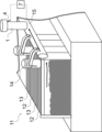
- FIG. 1 is a schematic diagram showing a combustion apparatus for coke oven emission gas according to an embodiment of the present invention, in which (a) represents a case where the hood has a single cylindrical shape, and (b) represents a case where the hood has a double cylindrical shape; and (c) an enlarged view of the blow pipe. It is an explanatory view of a coke oven provided with a combustion device according to the above embodiment.
- FIG. 2 is a schematic vertical cross-sectional view showing the combustion state of coke oven emission gas using the combustion apparatus according to the above embodiment, in which (a) represents the flow velocity distribution, and (b) represents the flow velocity vector and the temperature distribution.
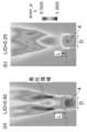
- FIG. 3 is a schematic vertical cross-sectional view showing the combustion state of coke oven emission gas using the combustion apparatus according to the above embodiment, and (a) is the distance L from the inner diameter D of the bleeder pipe and the tip of the bleeder pipe to the open end of the hood. The pressure distribution when the ratio L/D is 0.92 is shown, and (b) similarly shows the pressure distribution when the L/D is 0.25.
- Fig. 3 is a schematic vertical cross-sectional view showing the combustion state of coke oven emission gas using the combustion apparatus according to the above embodiment, and (a) is the distance L from the inner diameter D of the bleeder pipe and the tip of the bleeder pipe to the open end of the hood.
- 4 is a schematic vertical cross-sectional view for explaining a gap between an outer wall of a bleeder pipe and an inner wall of the hood and an inclination angle of the blow pipe in the combustion apparatus according to the embodiment; 4 is a graph showing the effect of the gap between the outer wall of the bleeder pipe and the inner wall of the hood and the inclination angle of the blow pipe on the ratio of the amount of soot produced in a coke oven emission gas combustion experiment using the combustion apparatus according to the above embodiment. . It is a schematic diagram explaining a conventional diffusion bleeder.
- C gas combustible gas
- a riser pipe 14 that collects the rising C gas and a dry main 15 that collects the C gas sucked up from the plurality of carbonization chambers 12 via the riser pipes 14 are provided.
- Diffusion bleeder 1 is connected to dry main 15 .
- C gas produced in a plurality of coking chambers 12 passes through risers 14 and dry mains 15 and is released into the atmosphere at diffusion bleeder 1 .
- the C gas produced from the carbonization chamber is sucked and collected by gas suction equipment (not shown) and reused as operating gas for various equipment.
- gas suction equipment not shown
- the C gas generated in the carbonization chamber cannot be sufficiently recovered and reused. Therefore, it is necessary to release the C gas into the atmosphere through the diffusion bleeder 1 as coke oven diffusion gas.
- the coke oven gas combustion apparatus includes a diffusion bleeder 1 and combustion promotion gas control means 7 .
- a dissipation bleeder 1 includes a hood 2, a bleeder pipe 3 and a blowing pipe 4.
- the hood 2 is a single cylindrical member, and in the example of FIG. 2(b), the hood is a double cylindrical member, but the present invention is not limited to these.
- the bleeder pipe 3 communicates with the dry main 15 of the coke oven 11, which generates the C gas 11G, at one end (not shown) (end face 3B at the bottom of the drawing), and passes the C gas 11G toward the hood 2.
- the C gas 11G flows from bottom to top.
- the hood 2 releases the C gas 11G supplied from the bleeder pipe 3 into the atmosphere from one end 2A (upper end) open to the atmosphere.
- the other end portion 3A of the bleeder pipe 3 is included inside the hood 2.
- the other end 2B (lower end surface) of the hood 2 is positioned below the other end 3A (upper end surface) of the bleeder pipe 3, so that the bleeder pipe 3 is located inside the hood 2.
- An enclosed region is formed.
- a gap 5 is formed between the inner wall of the hood 2 and the outer wall of the bleeder pipe 3 in the area where the bleeder pipe 3 is enclosed inside the hood 2 .
- An ignition device 6 is provided on the inner wall of the hood 2 to initially ignite the C gas 11G, which is the coke oven emission gas.
- a blowing pipe 4 capable of injecting gas (hereinafter referred to as "combustion promoting gas”) into the inside of the hood 2 from a gap 5 formed by the bleeder pipe 3 and the hood 2 is provided.
- the blow-in pipe 4 may be connected to, for example, a pump (not shown) so that the combustion promoting gas can be pumped.
- a pump not shown
- the combustion-promoting gas is blown from the blowing pipe 4 not only the combustion-promoting gas but also a gas such as air that is entrained from around the combustion-promoting gas and flows into the gap 5 due to the effect of the viscosity of the gas (hereinafter referred to as "accompanying gas”) gas) is generated.
- the combustion-promoting gas and accompanying gas injected into the gap 5 rise along the outer wall of the bleeder pipe 3, and eventually coke oven diffusion gas (C gas 11G) sent from the inside of the bleeder pipe 3 and the hood 2 It is mixed and stirred and mixed inside.
- the igniter 6 ignites the mixture.
- the gas discharged from the upper end of the hood 2 mixes with the outside air and burns, forming a flame (not shown) upward from the upper end surface of the bleeder pipe 3 .
- the mixed gas of the combustion accelerating gas, the C gas and the combustion gas from the blowing pipe 4 is discharged from the top of the hood 2 as a high-speed jet, as shown by the density distribution in FIG. 3(a).
- FIG. 3(a) the mixed gas of the combustion accelerating gas, the C gas and the combustion gas from the blowing pipe 4 is discharged from the top of the hood 2 as a high-speed jet, as shown by the density distribution in FIG. 3(a).
- control means 7 is provided for adjusting the flow rate, flow velocity or pressure of the combustion promoting gas blown into the blow pipe 4 . Based on the information on the C gas composition and flow rate, the control means 7 adjusts the blowing conditions of the combustion promoting gas so as to promote complete combustion of the coke oven stripping gas.
- the blow pipe 4 may be provided at a position where the combustion accelerating gas can be injected into the gap 5 , for example, the blow pipe 4 may be provided so that the upper end surface of the blow pipe 4 is positioned below the upper end surface of the bleeder pipe 3 .
- One or more blow pipes 4 may be provided for one set of bleeder pipe 3 and hood 2 combination, and a plurality of blow pipes 4 are provided along the circumferential direction of one bleeder pipe 3.
- the diffusion gas flow rate in the bleeder is MG [kg/s]
- the theoretical air flow rate required for combustion of the diffusion gas is M D [kg/s]
- the combustion promoting gas blown from the blow pipe The flow rate is M J [kg/s]
- the gas flow velocity is v J [m/s]
- the specific heat ratio is ⁇
- the blowing pressure is P J [Pa]
- the gas density is ⁇ J [kg/m 3 ]
- the blowing When the inner diameter of the incoming pipe is d [m] (see the enlarged view of FIG.
- EML cannot be theoretically determined due to pressure loss due to viscosity and flow velocity distribution in the jet, but EML based on the above idea is 370000 x ln(d) + 2300000 as shown in the example below. I found that I can express myself.
- the combustion-promoting gas is not particularly limited as long as it is gas, but in order to prevent explosion and incomplete combustion in the hood 2, it is preferably a non-flammable gas.
- the non-flammable gases air, nitrogen gas and water vapor are particularly preferred, either one or a mixture of two or more. Even when nitrogen gas, which does not contain oxygen, is used as the combustion-promoting gas, the high-speed jet entrains a sufficient amount of air (associated gas) as described above, and the oxygen and C gas contained in the entraining air are mixed. reacts, promoting complete combustion of C gas.
- the coke oven emission gas combustion apparatus of the present embodiment By applying the coke oven emission gas combustion apparatus of the present embodiment to the coke oven 11, even in the event of trouble such as a power failure, complete combustion of the C gas generated and diffused in the coking chamber 12 is promoted, and CO 2 and H 2 It can be released into the atmosphere as a less harmful substance such as O. Moreover, when applying to the coke oven 11, it is preferable to use air as the gas injected from the blowing pipe 4. FIG. By using air as the combustion-promoting gas in the factory compared to other gases, the combustion-promoting gas can be quickly and easily supplied to the diffusion bleeder 1 even in an emergency.
- the ratio L /D[-] is preferably in the range of 0.5 to 2.5.
- the high-speed jet A sufficient negative pressure region is generated from above the upper end face 3A of the bleeder pipe 3 in the hood 2.
- the ratio L/D is preferably 0.5 or more.
- the ratio L/D increases, energy is lost due to friction between fluids due to viscosity and friction between the fluid and the wall surface. Therefore, it is preferable to set the ratio L/D to 2.5 or less.
- a mechanism for reducing soot generation in the combustion apparatus according to this embodiment will be described with reference to FIG. 5 as an example.
- the jet FJ blown by the blowing pipe 4 is faster than the flow velocity of the C gas FU. Therefore, first, the C gas FU is involved in the hood 2 .
- the jet flow FJ that has sufficiently caught the C gas FU comes out of the hood 2, it involves a large amount of the atmosphere FA.
- the large amount of air lowers the combustion temperature and suppresses soot generation.
- the height of the hood 2 must be sufficiently secured.
- FIG. 5(b) if the height of the hood 2 is insufficient, the air outside the hood will be drawn in before the jet FJ sufficiently draws in the C gas, and the C gas and air will not be sufficiently mixed. become unable.
- the coke oven emission gas combustion apparatus includes information on the composition and generation amount of C gas grasped in advance, information on the flow meter installed in the bleeder pipe 3, or information on the C gas in the bleeder pipe 3. Based on the information obtained from the analysis, any one selected from the gas flow rate MJ , the gas flow velocity vJ , and the gas pressure PJ of the combustion promoting gas blown from the blowing pipe 4 so as to satisfy the above equation (1) or a combination of two or more.
- the control means can be composed of a computer or the like.
- the coke oven stripped gas combustion method using the coke oven stripped gas combustion apparatus according to the present embodiment is based on the composition and amount of C gas generated, the gas flow rate M J of the combustion promoting gas, the gas flow rate v J and the gas Any one selected from pressure PJ or a combination of two or more is adjusted.
- the method of designing a combustion apparatus for coke oven emission gas includes the composition range and generation amount transition of the coke oven emission gas grasped in advance, and the gas flow rate range and pressure of the controllable combustion promoting gas.
- the blow pipe inner diameter d [m] is designed so as to satisfy the above formula (1) from the range and physical properties.
- the gap 5 between the inner wall of the hood 2 and the outer wall of the bleeder pipe is designed to allow at least the blow pipe 4 to be inserted.
- Example 1 an attempt was made to quantitatively evaluate the amount of soot, which is the main component of black smoke, by simulation.
- NuFD / FrontFlowRed is used as simulation software to reproduce the combustion of coke oven gas by the diffusion bleeder, and the flame conditions (flame temperature) and without blowing pipe (conventional example) and with blowing pipe (invention example) ), the amount of soot generated was examined as a ratio of the amount of generated soot (conventional example was set to 1.0).
- the amount of soot generated was defined as the total amount of soot generated in the section where the total sum of soot in each cross section in the horizontal direction of the simulation was the maximum.
- FIG. 7 shows the results of a simulation of the amount of soot generated by fixing the ratio L/D to 10 5 [J/kg] and varying the ratio L/D.
- the ratio ⁇ of the amount of generated soot becomes the minimum value when the ratio L/D is approximately one.
- the ratio L/D is less than 1, the amount of soot produced increases sharply.
- L/D is greater than 1, the amount of generated soot also increases gradually.
- FIG. 7 shows that the ratio L/D is preferably in the range of 0.5 to 2.5.
- Example 2 As in Example 1, simulation software was used to determine that the gap W [m] between the outer wall of the bleeder pipe 3 and the inner wall of the hood 2 and the angle ⁇ [°] formed by the axial direction of the blow pipe are related to the generation of soot.
- Fig. 9 shows the results of the amount of soot generated when the inner diameter of the blowing pipe is d [m].
- the horizontal axis of FIG. 9 is W/(d ⁇ cos ⁇ ).
- the vertical axis indicates the ratio of the amount of soot generated.
- the angle ⁇ is too large, the upward component of motion will decrease and the lateral component of motion will increase.
- the angle ⁇ is preferably in the range of 0° or more and 30° or less.
- d ⁇ cos ⁇ is the area of the cross section of the blow pipe projected onto the gap between the hood and the bleeder pipe. Even if W/(d ⁇ cos ⁇ ) is less than 1, it falls within the preferable range because the jet flows so as to be attracted to the wall surface side by the Coanda effect between the jet and the wall surface. From FIG. 9, it was found that when W/(d ⁇ cos ⁇ ) is 0.85 or more, all the jets flow into the hood and the effect of suppressing soot generation can be efficiently obtained.
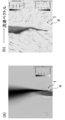
- FIG. 11(a1) shows a longitudinal section of a diffusion bleeder that does not blow gas.
- FIG. 11(c1) shows a blowing pipe 4A in the center of the bleeder pipe 3, as shown in FIG. 11(c1).
- Fluid simulation results are shown in FIGS. 11(a2), (b2) and (c2) for the conventional example, the invention example and the comparative example, respectively.
- the inventive example shows mixing of the jet with ambient air above the hood.
- the conventional example and the comparative example have a weaker force to draw in the ambient air than the invention example.
- coke oven emission gas combustion apparatus used when complete combustion is required to dissipate combustible gas into the atmosphere. Applicable.
Landscapes
- Engineering & Computer Science (AREA)
- Environmental & Geological Engineering (AREA)
- Mechanical Engineering (AREA)
- General Engineering & Computer Science (AREA)
- Coke Industry (AREA)
- Incineration Of Waste (AREA)
- Waste-Gas Treatment And Other Accessory Devices For Furnaces (AREA)
Abstract
Description
特許文献1に開示された技術では、フードからの空気取り込み量を制御するための部品やシステム等を新たに設ける必要があり、装置の構成や運転方法が複雑になってしまうという問題がある。特に放散ブリーダーのフードについて大幅な改造を施す必要がある。
{MJ/(MG+MD)}×{0.5×vJ 2+γ/(γ-1)×PJ/ρJ}
≧370000×ln(d)+2300000 (1)
ここで、MGは前記ブリーダー管内の放散ガス流量[kg/s]、
MDは放散ガスの燃焼に必要な理論空気流量[kg/s]、
γは比熱比、
ρJは燃焼促進ガスの密度[kg/m3]、
dは吹込み管の内径[m]
を表す。
(a)前記ブリーダー管の内径をD[m]とし、前記ブリーダー管の他端部先端から前記フードの一端部の先端までの距離をL[m]とした時に、その比L/Dが0.5以上2.5以下の範囲であること、
(b)前記ブリーダー管の外壁と前記フードの内壁との隙間をW[m]とし、前記吹込み管の内径をd[m]とし、前記ブリーダー管の軸方向と前記吹込み管の軸方向のなす角度をθ[°]とし、角度θが0°以上30°以下であって、W/(d・cosθ)の値が0.85~1.6の範囲にあること、
などが、より好ましい解決手段になり得るものと考えられる。
(c)前記ブリーダー管の内径をD[m]とし、前記ブリーダー管の他端部先端から前記フードの一端部の先端までの距離をL[m]とした時に、その比L/Dを0.5以上2.5以下の範囲とすること、
(d)前記ブリーダー管の外壁と前記フードの内壁との隙間をW[m]とし、前記吹込み管の内径をd[m]とし、前記ブリーダー管の軸方向と前記吹込み管の軸方向のなす角度をθ[°]とし、角度θを0°以上30°以下とし、W/(d・cosθ)の値を0.85~1.6の範囲とすること、
などが、より好ましい解決手段になり得るものと考えられる。
{MJ/(MG+MD)}×{0.5×vJ 2+γ/(γ-1)×PJ/ρJ}
≧370000×ln(d)+2300000 (1)
であることを満たすようにすれば、十分な大気巻込みにより、コークス炉放散ガスであるCガスの完全燃焼を促進することができる。複数の吹込み管が設置されている場合には、上記(1)式左辺をΣ[MJ×{0.5×vJ 2+γ/(γ-1)×PJ/ρJ}]/(MG+MD)とすればよい。Σは、吹込み管4の総和を表す。これは、燃焼促進ガスの流体エネルギー[MJ×{0.5×vJ 2+γ/(γ-1)×PJ/ρJ}]が周囲の大気を巻込みながら、放散ガスと放散ガス量を完全燃焼するために必要な空気の混合気(理論空気量)の噴流となる時点においても混合気がある一定のエネルギー{(MG+MD)×EML}[J]以上であればCガスの完全燃焼が促進され、黒煙(煤の発生)が低減されるという考えに基づいている。EMLは単位質量当たりのエネルギー[J/kg]である。燃焼促進ガスの流体エネルギーがCガスの完全燃焼に必要なエネルギーに比例すると仮定し、[MJ×{0.5×vJ 2+γ/(γ-1)×PJ/ρJ}]∝{(MG+MD)×EML}と置いた。(MG+MD)は事前に算出可能であることから、それを[MJ×{0.5×vJ 2+γ/(γ-1)×PJ/ρJ}]で除した数値と煤の発生量とを比較評価したところ、上記指標で整理できることがわかった。粘性による圧力損失および噴流内の流速分布があるためEMLを理論的に決めることができるわけではないが,前記の考えに基づくEMLは後述の実施例の通り370000×ln(d)+2300000と表現できることを見出した。
本実施例では,黒煙の主成分である煤の発生量をシミュレーションにより定量的に評価することを試みた。具体的にはシミュレーションソフトウェアとしてNuFD/FrontFlowRedを用い、放散ブリーダーによるコークス炉ガスの燃焼を再現し、火炎の状況(火炎温度)および、吹込み管なし(従来例)と吹込み管あり(発明例)で煤の発生量を発生量比(従来例を1.0とした。)として検討した。煤の発生量はシミュレーションの水平方向の各断面における煤の総和が最大となる断面の煤の総和量を煤の発生量として定義した。図6の縦軸に、従来例の煤最大量を基準として各吹込み条件の煤最大量の最大値の比φを示している。横軸は(1)式の左辺とした。これは燃焼促進ガスのもつエネルギーをコークス炉ガスの質量流量とコークス炉ガスの完全燃焼に必要な空気の質量流量の和で除したものである。図6によれば、吹込み管4の異なる内径d毎に煤の発生量の比φは(1)式左辺がある一定値以上となると急激に低減することが分かる。煤の発生量の比φを、シグモイド関数を用いて近似曲線を併記した。φ=1-{1/(1+e-α(x-β))}とおいて、α=0.00005、β=370000×ln(d)+2300000すると各々のプロットをおおよそ曲線で近似表現できることが分かった。ここで、βは、関数の変曲点あり、かつ、φが0.5になる点つまり煤発生量が従来例に対して0.5となる点である。以上より上記(1)式を満足することでCガスの完全燃焼が促進され,黒煙(煤の発生)が低減されるということを示している.
実施例1と同様に、シミュレーションソフトウェアを用いて、ブリーダー管3の外壁とフード2の内壁との隙間W[m]と吹込み管の軸方向のなす角度θ[°]とが煤の発生に与える影響を検討した。吹込み管の内径をd[m]として、図9に煤発生量の結果を示す。図9の横軸はW/(d・cosθ)と置いた。縦軸は実施例1と同様煤発生量の比を示す。加えて、角度θが大きすぎる場合、上向きの運動成分が小さくなり横向きの運動成分が増加する。そのため噴流がブリーダー管に衝突する際に、噴流が広範囲に広がってしまい、噴流吹きこみによる煤低減効果が十分に得られない。したがって、角度θは0°以上30°以下の範囲が好ましい。
従来例として、ガス吹き込みのない放散ブリーダーの縦断面を図11(a1)に示す。発明例として、上記実施形態にかかる吹き込み管4の配置を図11(b1)に示す。比較例として、ブリーダー管3の中央に吹き込み管4Aを配置して図11(c1)に示す。流体シミュレーション結果を、従来例、発明例および比較例についてそれぞれ図11(a2)、(b2)および(c2)に示す。発明例は、フードの上方で周辺大気と噴流が混合していることを示している。一方、従来例および比較例は、発明例と比べて、周辺大気を引き込む力が弱いことがわかる。
2 フード
2A フードの上端面
2B フードの下端面
3 ブリーダー管
3A ブリーダー管の上端面
3B ブリーダー管のコークス炉側端部
4 吹込み管
4A (ブリーダー管中央の)吹込み管
5 間隙(ブリーダー管外壁とフード内壁との間隙)
6 点火装置
7 制御手段
11 コークス炉
11G コークス炉ガス(Cガス、可燃性ガス)
12 炭化室
13 燃焼室
14 上昇管
15 ドライメーン
d 吹込み管内径
D ブリーダー管上端径
L ブリーダー管上端からフード開放端までの距離
W ブリーダー管外壁とフード内壁との隙間の距離
FJ 噴流
FA 大気(空気)
FU 可燃性ガス(Cガス)
Claims (7)
- 一端部がコークス炉放散ガスの発生部と連通し、内側にコークス炉放散ガスを通すブリーダー管と、
前記ブリーダー管の他端部の軸線と同軸に配置され、一端部が大気側に開放されるとともに、他端部が前記ブリーダー管の他端部を内包する、少なくとも一の円筒からなるフードと、
前記ブリーダー管の外壁と前記フードの内壁との隙間に下方より挿入されたガス吹込み管と、
前記ガス吹込み管から吹き込む燃焼促進ガスの吹込み条件を調整する制御手段と、
を備え、
前記制御手段は、下記(1)式を満足するように、前記吹込み管から吹き込む前記燃焼促進ガスのガス流量MJ[kg/s]、ガス流速vJ[m/s]およびガス圧力PJ[Pa]から選ばれるいずれか一つを、または、二つ以上を組み合わせて調整するように構成される、コークス炉放散ガスの燃焼装置。
{MJ/(MG+MD)}×{0.5×vJ 2+γ/(γ-1)×PJ/ρJ}
≧370000×ln(d)+2300000 (1)
ここで、MGは前記ブリーダー管内の放散ガス流量[kg/s]、
MDは放散ガスの燃焼に必要な理論空気流量[kg/s]、
γは比熱比、
ρJは燃焼促進ガスの密度[kg/m3]、
dは吹込み管の内径[m]
を表す。 - 前記ブリーダー管の内径をD[m]とし、前記ブリーダー管の他端部先端から前記フードの一端部の先端までの距離をL[m]とした時に、その比L/Dが0.5以上2.5以下の範囲である、請求項1に記載のコークス炉放散ガスの燃焼装置。
- 前記ブリーダー管の外壁と前記フードの内壁との隙間をW[m]とし、前記吹込み管の内径をd[m]とし、前記ブリーダー管の軸方向と前記吹込み管の軸方向のなす角度をθ[°]とし、角度θが0°以上30°以下であって、W/(d・cosθ)の値が0.85~1.6の範囲にある、請求項1または2に記載のコークス炉放散ガスの燃焼装置。
- 一端部がコークス炉放散ガスの発生部と連通するブリーダー管の内側にコークス炉放散ガスを通し、
前記ブリーダー管の他端部の軸線と同軸に配置され、一端部が大気側に開放されるとともに、他端部が前記ブリーダー管の他端部を内包する、少なくとも一の円筒からなるフードの内壁と前記ブリーダー管の外壁との間に挿入された吹込み管から燃焼促進ガスを吹き込むにあたり、
下記(1)式を満足するように、前記吹込み管から吹き込む前記燃焼促進ガスのガス流量MJ[kg/s]、ガス流速vJ[m/s]およびガス圧力PJ[Pa]から選ばれるいずれか一つを、または、二つ以上を組み合わせて調整する、コークス炉放散ガスの燃焼方法。
{MJ/(MG+MD)}×{0.5×vJ 2+γ/(γ-1)×PJ/ρJ}
≧370000×ln(d)+2300000 (1)
ここで、MGは前記ブリーダー管内の放散ガス流量[kg/s]、
MDは放散ガスの燃焼に必要な理論空気流量[kg/s]、
γは比熱比、
ρJは燃焼促進ガスの密度[kg/m3]、
dは吹込み管の内径[m]
を表す。 - 一端部がコークス炉放散ガスの発生部と連通し、内側にコークス炉放散ガスを通すブリーダー管と、
前記ブリーダー管の他端部の軸線と同軸に配置され、一端部が大気側に開放されるとともに、他端部が前記ブリーダー管の他端部を内包する、少なくとも一の円筒からなるフードと、
前記ブリーダー管の外壁と前記フードの内壁との隙間に下方より挿入されたガス吹込み管と、
前記ガス吹込み管から吹き込む燃焼促進ガスの吹込み条件を調整する制御手段と、
を備えるコークス炉放散ガスの燃焼装置を設計するにあたり、
下記(1)式を満足するように、吹込み管の内径d[m]を設計する、コークス炉放散ガスの燃焼装置の設計方法。
{MJ/(MG+MD)}×{0.5×vJ 2+γ/(γ-1)×PJ/ρJ}
≧370000×ln(d)+2300000 (1)
ここで、MJは前記吹込み管から吹き込む前記燃焼促進ガスのガス流量[kg/s]、
MGは前記ブリーダー管内の放散ガス流量[kg/s]、
MDは放散ガスの燃焼に必要な理論空気流量[kg/s]、
vJは前記吹込み管から吹き込む前記燃焼促進ガスのガス流速[m/s]、
γは比熱比、
PJは前記吹込み管から吹き込む前記燃焼促進ガスのガス圧力[Pa]、
ρJは燃焼促進ガスの密度[kg/m3]
を表す。 - 前記ブリーダー管の内径をD[m]とし、前記ブリーダー管の他端部先端から前記フードの一端部の先端までの距離をL[m]とした時に、その比L/Dを0.5以上2.5以下の範囲とする、請求項5に記載のコークス炉放散ガスの燃焼装置の設計方法。
- 前記ブリーダー管の外壁と前記フードの内壁との隙間をW[m]とし、前記吹込み管の内径をd[m]とし、前記ブリーダー管の軸方向と前記吹込み管の軸方向のなす角度をθ[°]とし、角度θを0°以上30°以下とし、W/(d・cosθ)の値を0.85~1.6の範囲とする、請求項5または6に記載のコークス炉放散ガスの燃焼装置の設計方法。
Priority Applications (2)
| Application Number | Priority Date | Filing Date | Title |
|---|---|---|---|
| JP2023514457A JPWO2023145219A1 (ja) | 2022-01-28 | 2022-11-22 | |
| EP22924071.8A EP4467875A4 (en) | 2022-01-28 | 2022-11-22 | Device for combusting coke oven emission gases, method of combusting coke oven emission gases, and method of designing device for combusting coke oven emission gases |
Applications Claiming Priority (2)
| Application Number | Priority Date | Filing Date | Title |
|---|---|---|---|
| JP2022011501 | 2022-01-28 | ||
| JP2022-011501 | 2022-01-28 |
Publications (1)
| Publication Number | Publication Date |
|---|---|
| WO2023145219A1 true WO2023145219A1 (ja) | 2023-08-03 |
Family
ID=87471412
Family Applications (1)
| Application Number | Title | Priority Date | Filing Date |
|---|---|---|---|
| PCT/JP2022/043090 Ceased WO2023145219A1 (ja) | 2022-01-28 | 2022-11-22 | コークス炉放散ガスの燃焼装置、コークス炉放散ガスの燃焼方法およびコークス炉放散ガスの燃焼装置の設計方法 |
Country Status (4)
| Country | Link |
|---|---|
| EP (1) | EP4467875A4 (ja) |
| JP (1) | JPWO2023145219A1 (ja) |
| TW (1) | TWI852282B (ja) |
| WO (1) | WO2023145219A1 (ja) |
Citations (7)
| Publication number | Priority date | Publication date | Assignee | Title |
|---|---|---|---|---|
| US4643669A (en) | 1985-08-26 | 1987-02-17 | Peabody Engineering Corporation | Smokeless flare gas burner |
| JP2002534653A (ja) | 1998-12-30 | 2002-10-15 | トータル、ラフィナージュ、ディストリビュシオン、ソシエテ、アノニム | ガス燃焼のためのバーナー式装置および方法 |
| JP2004537702A (ja) | 2001-04-18 | 2004-12-16 | サウジ アラビアン オイル カンパニー | フレアスタック燃焼装置および方法 |
| JP2010236856A (ja) | 2004-12-02 | 2010-10-21 | Saudi Arabian Oil Co | フレアスタック燃焼方法および装置 |
| JP2010286230A (ja) | 2009-05-12 | 2010-12-24 | John Zink Co Llc | 空気フレア装置及び方法 |
| JP2017096615A (ja) * | 2015-11-18 | 2017-06-01 | Jfeスチール株式会社 | 放散ブリーダー |
| JP2020117623A (ja) | 2019-01-23 | 2020-08-06 | 日本製鉄株式会社 | コークス炉ガスの燃焼放散管 |
Family Cites Families (1)
| Publication number | Priority date | Publication date | Assignee | Title |
|---|---|---|---|---|
| CN103499097B (zh) * | 2013-09-29 | 2016-05-11 | 北京华清燃气轮机与煤气化联合循环工程技术有限公司 | 一种燃用中低热值燃料气的燃烧室燃烧组织方法及喷嘴 |
-
2022
- 2022-11-22 EP EP22924071.8A patent/EP4467875A4/en active Pending
- 2022-11-22 JP JP2023514457A patent/JPWO2023145219A1/ja active Pending
- 2022-11-22 WO PCT/JP2022/043090 patent/WO2023145219A1/ja not_active Ceased
-
2023
- 2023-01-12 TW TW112101377A patent/TWI852282B/zh active
Patent Citations (7)
| Publication number | Priority date | Publication date | Assignee | Title |
|---|---|---|---|---|
| US4643669A (en) | 1985-08-26 | 1987-02-17 | Peabody Engineering Corporation | Smokeless flare gas burner |
| JP2002534653A (ja) | 1998-12-30 | 2002-10-15 | トータル、ラフィナージュ、ディストリビュシオン、ソシエテ、アノニム | ガス燃焼のためのバーナー式装置および方法 |
| JP2004537702A (ja) | 2001-04-18 | 2004-12-16 | サウジ アラビアン オイル カンパニー | フレアスタック燃焼装置および方法 |
| JP2010236856A (ja) | 2004-12-02 | 2010-10-21 | Saudi Arabian Oil Co | フレアスタック燃焼方法および装置 |
| JP2010286230A (ja) | 2009-05-12 | 2010-12-24 | John Zink Co Llc | 空気フレア装置及び方法 |
| JP2017096615A (ja) * | 2015-11-18 | 2017-06-01 | Jfeスチール株式会社 | 放散ブリーダー |
| JP2020117623A (ja) | 2019-01-23 | 2020-08-06 | 日本製鉄株式会社 | コークス炉ガスの燃焼放散管 |
Non-Patent Citations (1)
| Title |
|---|
| See also references of EP4467875A4 |
Also Published As
| Publication number | Publication date |
|---|---|
| EP4467875A4 (en) | 2025-04-23 |
| JPWO2023145219A1 (ja) | 2023-08-03 |
| TWI852282B (zh) | 2024-08-11 |
| TW202344777A (zh) | 2023-11-16 |
| EP4467875A1 (en) | 2024-11-27 |
Similar Documents
| Publication | Publication Date | Title |
|---|---|---|
| EP2294336B1 (en) | Low nox burner | |
| JPH0611120A (ja) | 低NOx生成ガスバーナ装置とその方法 | |
| JP2017096615A (ja) | 放散ブリーダー | |
| US3982881A (en) | Invisible flare burner | |
| KR20100098632A (ko) | 비화염 열 산화 장치 및 방법 | |
| JPH0243083B2 (ja) | ||
| US20050271990A1 (en) | Energy efficient low NOx burner and method of operating same | |
| WO2023145219A1 (ja) | コークス炉放散ガスの燃焼装置、コークス炉放散ガスの燃焼方法およびコークス炉放散ガスの燃焼装置の設計方法 | |
| CN1110648C (zh) | 燃烧易燃气体的设备和方法 | |
| CN109073218B (zh) | 焚烧系统 | |
| US5823759A (en) | Apparatus and method for burning combustible gases | |
| RU2745312C1 (ru) | Факел для отработанного газа с низким потреблением пара и высокими возможностями бездымной работы | |
| JP6260555B2 (ja) | 還元材吹き込み装置 | |
| JPS5816083B2 (ja) | 燃焼装置 | |
| WO2015029424A1 (ja) | 高炉操業方法 | |
| JP7207618B1 (ja) | 放散ブリーダー | |
| KR100551984B1 (ko) | 산업용 저녹스 버너 | |
| JP7563345B2 (ja) | コークス炉放散ガスの燃焼方法およびコークス炉放散ブリーダー | |
| US653166A (en) | Open bunsen burner. | |
| JPH11223315A (ja) | 未燃焼ガス燃焼用バ−ナ | |
| JP4914612B2 (ja) | 焼却炉用空気導入装置 | |
| JPS6071812A (ja) | 微粉燃焼用バ−ナ装置 | |
| JP2006057903A (ja) | 微粉炭バーナおよびこれを用いたボイラ | |
| JPS59147909A (ja) | 燃焼方法 | |
| JP2001141221A (ja) | 焼却炉 |
Legal Events
| Date | Code | Title | Description |
|---|---|---|---|
| WWE | Wipo information: entry into national phase |
Ref document number: 2023514457 Country of ref document: JP |
|
| 121 | Ep: the epo has been informed by wipo that ep was designated in this application |
Ref document number: 22924071 Country of ref document: EP Kind code of ref document: A1 |
|
| REG | Reference to national code |
Ref country code: BR Ref legal event code: B01A Ref document number: 112024015416 Country of ref document: BR |
|
| WWE | Wipo information: entry into national phase |
Ref document number: 202417063390 Country of ref document: IN Ref document number: 2022924071 Country of ref document: EP |
|
| ENP | Entry into the national phase |
Ref document number: 2022924071 Country of ref document: EP Effective date: 20240822 |
|
| NENP | Non-entry into the national phase |
Ref country code: DE |
|
| ENP | Entry into the national phase |
Ref document number: 112024015416 Country of ref document: BR Kind code of ref document: A2 Effective date: 20240726 |