WO2023149035A1 - 電動作業車 - Google Patents
電動作業車 Download PDFInfo
- Publication number
- WO2023149035A1 WO2023149035A1 PCT/JP2022/040738 JP2022040738W WO2023149035A1 WO 2023149035 A1 WO2023149035 A1 WO 2023149035A1 JP 2022040738 W JP2022040738 W JP 2022040738W WO 2023149035 A1 WO2023149035 A1 WO 2023149035A1
- Authority
- WO
- WIPO (PCT)
- Prior art keywords
- battery
- temperature
- power
- electric motor
- control device
- Prior art date
- Legal status (The legal status is an assumption and is not a legal conclusion. Google has not performed a legal analysis and makes no representation as to the accuracy of the status listed.)
- Ceased
Links
Images


Classifications
-
- B—PERFORMING OPERATIONS; TRANSPORTING
- B60—VEHICLES IN GENERAL
- B60L—PROPULSION OF ELECTRICALLY-PROPELLED VEHICLES; SUPPLYING ELECTRIC POWER FOR AUXILIARY EQUIPMENT OF ELECTRICALLY-PROPELLED VEHICLES; ELECTRODYNAMIC BRAKE SYSTEMS FOR VEHICLES IN GENERAL; MAGNETIC SUSPENSION OR LEVITATION FOR VEHICLES; MONITORING OPERATING VARIABLES OF ELECTRICALLY-PROPELLED VEHICLES; ELECTRIC SAFETY DEVICES FOR ELECTRICALLY-PROPELLED VEHICLES
- B60L53/00—Methods of charging batteries, specially adapted for electric vehicles; Charging stations or on-board charging equipment therefor; Exchange of energy storage elements in electric vehicles
- B60L53/10—Methods of charging batteries, specially adapted for electric vehicles; Charging stations or on-board charging equipment therefor; Exchange of energy storage elements in electric vehicles characterised by the energy transfer between the charging station and the vehicle
- B60L53/14—Conductive energy transfer
-
- B—PERFORMING OPERATIONS; TRANSPORTING
- B60—VEHICLES IN GENERAL
- B60L—PROPULSION OF ELECTRICALLY-PROPELLED VEHICLES; SUPPLYING ELECTRIC POWER FOR AUXILIARY EQUIPMENT OF ELECTRICALLY-PROPELLED VEHICLES; ELECTRODYNAMIC BRAKE SYSTEMS FOR VEHICLES IN GENERAL; MAGNETIC SUSPENSION OR LEVITATION FOR VEHICLES; MONITORING OPERATING VARIABLES OF ELECTRICALLY-PROPELLED VEHICLES; ELECTRIC SAFETY DEVICES FOR ELECTRICALLY-PROPELLED VEHICLES
- B60L58/00—Methods or circuit arrangements for monitoring or controlling batteries or fuel cells, specially adapted for electric vehicles
- B60L58/10—Methods or circuit arrangements for monitoring or controlling batteries or fuel cells, specially adapted for electric vehicles for monitoring or controlling batteries
- B60L58/24—Methods or circuit arrangements for monitoring or controlling batteries or fuel cells, specially adapted for electric vehicles for monitoring or controlling batteries for controlling the temperature of batteries
- B60L58/27—Methods or circuit arrangements for monitoring or controlling batteries or fuel cells, specially adapted for electric vehicles for monitoring or controlling batteries for controlling the temperature of batteries by heating
-
- B—PERFORMING OPERATIONS; TRANSPORTING
- B60—VEHICLES IN GENERAL
- B60L—PROPULSION OF ELECTRICALLY-PROPELLED VEHICLES; SUPPLYING ELECTRIC POWER FOR AUXILIARY EQUIPMENT OF ELECTRICALLY-PROPELLED VEHICLES; ELECTRODYNAMIC BRAKE SYSTEMS FOR VEHICLES IN GENERAL; MAGNETIC SUSPENSION OR LEVITATION FOR VEHICLES; MONITORING OPERATING VARIABLES OF ELECTRICALLY-PROPELLED VEHICLES; ELECTRIC SAFETY DEVICES FOR ELECTRICALLY-PROPELLED VEHICLES
- B60L1/00—Supplying electric power to auxiliary equipment of vehicles
- B60L1/003—Supplying electric power to auxiliary equipment of vehicles to auxiliary motors, e.g. for pumps, compressors
-
- B—PERFORMING OPERATIONS; TRANSPORTING
- B60—VEHICLES IN GENERAL
- B60L—PROPULSION OF ELECTRICALLY-PROPELLED VEHICLES; SUPPLYING ELECTRIC POWER FOR AUXILIARY EQUIPMENT OF ELECTRICALLY-PROPELLED VEHICLES; ELECTRODYNAMIC BRAKE SYSTEMS FOR VEHICLES IN GENERAL; MAGNETIC SUSPENSION OR LEVITATION FOR VEHICLES; MONITORING OPERATING VARIABLES OF ELECTRICALLY-PROPELLED VEHICLES; ELECTRIC SAFETY DEVICES FOR ELECTRICALLY-PROPELLED VEHICLES
- B60L50/00—Electric propulsion with power supplied within the vehicle
- B60L50/50—Electric propulsion with power supplied within the vehicle using propulsion power supplied by batteries or fuel cells
- B60L50/60—Electric propulsion with power supplied within the vehicle using propulsion power supplied by batteries or fuel cells using power supplied by batteries
-
- B—PERFORMING OPERATIONS; TRANSPORTING
- B60—VEHICLES IN GENERAL
- B60L—PROPULSION OF ELECTRICALLY-PROPELLED VEHICLES; SUPPLYING ELECTRIC POWER FOR AUXILIARY EQUIPMENT OF ELECTRICALLY-PROPELLED VEHICLES; ELECTRODYNAMIC BRAKE SYSTEMS FOR VEHICLES IN GENERAL; MAGNETIC SUSPENSION OR LEVITATION FOR VEHICLES; MONITORING OPERATING VARIABLES OF ELECTRICALLY-PROPELLED VEHICLES; ELECTRIC SAFETY DEVICES FOR ELECTRICALLY-PROPELLED VEHICLES
- B60L53/00—Methods of charging batteries, specially adapted for electric vehicles; Charging stations or on-board charging equipment therefor; Exchange of energy storage elements in electric vehicles
- B60L53/60—Monitoring or controlling charging stations
- B60L53/62—Monitoring or controlling charging stations in response to charging parameters, e.g. current, voltage or electrical charge
-
- B—PERFORMING OPERATIONS; TRANSPORTING
- B60—VEHICLES IN GENERAL
- B60L—PROPULSION OF ELECTRICALLY-PROPELLED VEHICLES; SUPPLYING ELECTRIC POWER FOR AUXILIARY EQUIPMENT OF ELECTRICALLY-PROPELLED VEHICLES; ELECTRODYNAMIC BRAKE SYSTEMS FOR VEHICLES IN GENERAL; MAGNETIC SUSPENSION OR LEVITATION FOR VEHICLES; MONITORING OPERATING VARIABLES OF ELECTRICALLY-PROPELLED VEHICLES; ELECTRIC SAFETY DEVICES FOR ELECTRICALLY-PROPELLED VEHICLES
- B60L58/00—Methods or circuit arrangements for monitoring or controlling batteries or fuel cells, specially adapted for electric vehicles
- B60L58/10—Methods or circuit arrangements for monitoring or controlling batteries or fuel cells, specially adapted for electric vehicles for monitoring or controlling batteries
- B60L58/24—Methods or circuit arrangements for monitoring or controlling batteries or fuel cells, specially adapted for electric vehicles for monitoring or controlling batteries for controlling the temperature of batteries
- B60L58/25—Methods or circuit arrangements for monitoring or controlling batteries or fuel cells, specially adapted for electric vehicles for monitoring or controlling batteries for controlling the temperature of batteries by controlling the electric load
-
- B—PERFORMING OPERATIONS; TRANSPORTING
- B60—VEHICLES IN GENERAL
- B60L—PROPULSION OF ELECTRICALLY-PROPELLED VEHICLES; SUPPLYING ELECTRIC POWER FOR AUXILIARY EQUIPMENT OF ELECTRICALLY-PROPELLED VEHICLES; ELECTRODYNAMIC BRAKE SYSTEMS FOR VEHICLES IN GENERAL; MAGNETIC SUSPENSION OR LEVITATION FOR VEHICLES; MONITORING OPERATING VARIABLES OF ELECTRICALLY-PROPELLED VEHICLES; ELECTRIC SAFETY DEVICES FOR ELECTRICALLY-PROPELLED VEHICLES
- B60L58/00—Methods or circuit arrangements for monitoring or controlling batteries or fuel cells, specially adapted for electric vehicles
- B60L58/10—Methods or circuit arrangements for monitoring or controlling batteries or fuel cells, specially adapted for electric vehicles for monitoring or controlling batteries
- B60L58/24—Methods or circuit arrangements for monitoring or controlling batteries or fuel cells, specially adapted for electric vehicles for monitoring or controlling batteries for controlling the temperature of batteries
- B60L58/26—Methods or circuit arrangements for monitoring or controlling batteries or fuel cells, specially adapted for electric vehicles for monitoring or controlling batteries for controlling the temperature of batteries by cooling
-
- H—ELECTRICITY
- H01—ELECTRIC ELEMENTS
- H01M—PROCESSES OR MEANS, e.g. BATTERIES, FOR THE DIRECT CONVERSION OF CHEMICAL ENERGY INTO ELECTRICAL ENERGY
- H01M10/00—Secondary cells; Manufacture thereof
- H01M10/42—Methods or arrangements for servicing or maintenance of secondary cells or secondary half-cells
- H01M10/44—Methods for charging or discharging
- H01M10/443—Methods for charging or discharging in response to temperature
-
- H—ELECTRICITY
- H01—ELECTRIC ELEMENTS
- H01M—PROCESSES OR MEANS, e.g. BATTERIES, FOR THE DIRECT CONVERSION OF CHEMICAL ENERGY INTO ELECTRICAL ENERGY
- H01M10/00—Secondary cells; Manufacture thereof
- H01M10/42—Methods or arrangements for servicing or maintenance of secondary cells or secondary half-cells
- H01M10/48—Accumulators combined with arrangements for measuring, testing or indicating the condition of cells, e.g. the level or density of the electrolyte
- H01M10/486—Accumulators combined with arrangements for measuring, testing or indicating the condition of cells, e.g. the level or density of the electrolyte for measuring temperature
-
- H—ELECTRICITY
- H01—ELECTRIC ELEMENTS
- H01M—PROCESSES OR MEANS, e.g. BATTERIES, FOR THE DIRECT CONVERSION OF CHEMICAL ENERGY INTO ELECTRICAL ENERGY
- H01M10/00—Secondary cells; Manufacture thereof
- H01M10/60—Heating or cooling; Temperature control
- H01M10/62—Heating or cooling; Temperature control specially adapted for specific applications
- H01M10/625—Vehicles
-
- H—ELECTRICITY
- H01—ELECTRIC ELEMENTS
- H01M—PROCESSES OR MEANS, e.g. BATTERIES, FOR THE DIRECT CONVERSION OF CHEMICAL ENERGY INTO ELECTRICAL ENERGY
- H01M10/00—Secondary cells; Manufacture thereof
- H01M10/60—Heating or cooling; Temperature control
- H01M10/63—Control systems
-
- H—ELECTRICITY
- H01—ELECTRIC ELEMENTS
- H01M—PROCESSES OR MEANS, e.g. BATTERIES, FOR THE DIRECT CONVERSION OF CHEMICAL ENERGY INTO ELECTRICAL ENERGY
- H01M10/00—Secondary cells; Manufacture thereof
- H01M10/60—Heating or cooling; Temperature control
- H01M10/63—Control systems
- H01M10/633—Control systems characterised by algorithms, flow charts, software details or the like
-
- H—ELECTRICITY
- H01—ELECTRIC ELEMENTS
- H01M—PROCESSES OR MEANS, e.g. BATTERIES, FOR THE DIRECT CONVERSION OF CHEMICAL ENERGY INTO ELECTRICAL ENERGY
- H01M10/00—Secondary cells; Manufacture thereof
- H01M10/60—Heating or cooling; Temperature control
- H01M10/65—Means for temperature control structurally associated with the cells
- H01M10/656—Means for temperature control structurally associated with the cells characterised by the type of heat-exchange fluid
- H01M10/6567—Liquids
- H01M10/6568—Liquids characterised by flow circuits, e.g. loops, located externally to the cells or cell casings
-
- H—ELECTRICITY
- H01—ELECTRIC ELEMENTS
- H01M—PROCESSES OR MEANS, e.g. BATTERIES, FOR THE DIRECT CONVERSION OF CHEMICAL ENERGY INTO ELECTRICAL ENERGY
- H01M10/00—Secondary cells; Manufacture thereof
- H01M10/60—Heating or cooling; Temperature control
- H01M10/66—Heat-exchange relationships between the cells and other systems, e.g. central heating systems or fuel cells
- H01M10/663—Heat-exchange relationships between the cells and other systems, e.g. central heating systems or fuel cells the system being an air-conditioner or an engine
-
- H—ELECTRICITY
- H02—GENERATION; CONVERSION OR DISTRIBUTION OF ELECTRIC POWER
- H02J—ELECTRIC POWER NETWORKS; CIRCUIT ARRANGEMENTS OR SYSTEMS FOR SUPPLYING OR DISTRIBUTING ELECTRIC POWER; SYSTEMS FOR STORING ELECTRIC ENERGY
- H02J7/00—Circuit arrangements for charging or discharging batteries or for supplying loads from batteries
- H02J7/90—Regulation of charging or discharging current or voltage
- H02J7/971—Regulation of charging or discharging current or voltage the charge cycle being controlled or terminated in response to non-electric parameters
- H02J7/975—Regulation of charging or discharging current or voltage the charge cycle being controlled or terminated in response to non-electric parameters in response to temperature
-
- A—HUMAN NECESSITIES
- A01—AGRICULTURE; FORESTRY; ANIMAL HUSBANDRY; HUNTING; TRAPPING; FISHING
- A01D—HARVESTING; MOWING
- A01D2101/00—Lawn-mowers
-
- A—HUMAN NECESSITIES
- A01—AGRICULTURE; FORESTRY; ANIMAL HUSBANDRY; HUNTING; TRAPPING; FISHING
- A01D—HARVESTING; MOWING
- A01D34/00—Mowers; Mowing apparatus of harvesters
- A01D34/01—Mowers; Mowing apparatus of harvesters characterised by features relating to the type of cutting apparatus
- A01D34/412—Mowers; Mowing apparatus of harvesters characterised by features relating to the type of cutting apparatus having rotating cutters
- A01D34/63—Mowers; Mowing apparatus of harvesters characterised by features relating to the type of cutting apparatus having rotating cutters having cutters rotating about a vertical axis
- A01D34/76—Driving mechanisms for the cutters
- A01D34/78—Driving mechanisms for the cutters electric
-
- B—PERFORMING OPERATIONS; TRANSPORTING
- B60—VEHICLES IN GENERAL
- B60L—PROPULSION OF ELECTRICALLY-PROPELLED VEHICLES; SUPPLYING ELECTRIC POWER FOR AUXILIARY EQUIPMENT OF ELECTRICALLY-PROPELLED VEHICLES; ELECTRODYNAMIC BRAKE SYSTEMS FOR VEHICLES IN GENERAL; MAGNETIC SUSPENSION OR LEVITATION FOR VEHICLES; MONITORING OPERATING VARIABLES OF ELECTRICALLY-PROPELLED VEHICLES; ELECTRIC SAFETY DEVICES FOR ELECTRICALLY-PROPELLED VEHICLES
- B60L2200/00—Type of vehicles
- B60L2200/40—Working vehicles
-
- B—PERFORMING OPERATIONS; TRANSPORTING
- B60—VEHICLES IN GENERAL
- B60L—PROPULSION OF ELECTRICALLY-PROPELLED VEHICLES; SUPPLYING ELECTRIC POWER FOR AUXILIARY EQUIPMENT OF ELECTRICALLY-PROPELLED VEHICLES; ELECTRODYNAMIC BRAKE SYSTEMS FOR VEHICLES IN GENERAL; MAGNETIC SUSPENSION OR LEVITATION FOR VEHICLES; MONITORING OPERATING VARIABLES OF ELECTRICALLY-PROPELLED VEHICLES; ELECTRIC SAFETY DEVICES FOR ELECTRICALLY-PROPELLED VEHICLES
- B60L2210/00—Converter types
- B60L2210/40—DC to AC converters
-
- B—PERFORMING OPERATIONS; TRANSPORTING
- B60—VEHICLES IN GENERAL
- B60L—PROPULSION OF ELECTRICALLY-PROPELLED VEHICLES; SUPPLYING ELECTRIC POWER FOR AUXILIARY EQUIPMENT OF ELECTRICALLY-PROPELLED VEHICLES; ELECTRODYNAMIC BRAKE SYSTEMS FOR VEHICLES IN GENERAL; MAGNETIC SUSPENSION OR LEVITATION FOR VEHICLES; MONITORING OPERATING VARIABLES OF ELECTRICALLY-PROPELLED VEHICLES; ELECTRIC SAFETY DEVICES FOR ELECTRICALLY-PROPELLED VEHICLES
- B60L2240/00—Control parameters of input or output; Target parameters
- B60L2240/10—Vehicle control parameters
- B60L2240/36—Temperature of vehicle components or parts
-
- B—PERFORMING OPERATIONS; TRANSPORTING
- B60—VEHICLES IN GENERAL
- B60L—PROPULSION OF ELECTRICALLY-PROPELLED VEHICLES; SUPPLYING ELECTRIC POWER FOR AUXILIARY EQUIPMENT OF ELECTRICALLY-PROPELLED VEHICLES; ELECTRODYNAMIC BRAKE SYSTEMS FOR VEHICLES IN GENERAL; MAGNETIC SUSPENSION OR LEVITATION FOR VEHICLES; MONITORING OPERATING VARIABLES OF ELECTRICALLY-PROPELLED VEHICLES; ELECTRIC SAFETY DEVICES FOR ELECTRICALLY-PROPELLED VEHICLES
- B60L2240/00—Control parameters of input or output; Target parameters
- B60L2240/40—Drive Train control parameters
- B60L2240/42—Drive Train control parameters related to electric machines
- B60L2240/421—Speed
-
- B—PERFORMING OPERATIONS; TRANSPORTING
- B60—VEHICLES IN GENERAL
- B60L—PROPULSION OF ELECTRICALLY-PROPELLED VEHICLES; SUPPLYING ELECTRIC POWER FOR AUXILIARY EQUIPMENT OF ELECTRICALLY-PROPELLED VEHICLES; ELECTRODYNAMIC BRAKE SYSTEMS FOR VEHICLES IN GENERAL; MAGNETIC SUSPENSION OR LEVITATION FOR VEHICLES; MONITORING OPERATING VARIABLES OF ELECTRICALLY-PROPELLED VEHICLES; ELECTRIC SAFETY DEVICES FOR ELECTRICALLY-PROPELLED VEHICLES
- B60L2240/00—Control parameters of input or output; Target parameters
- B60L2240/40—Drive Train control parameters
- B60L2240/54—Drive Train control parameters related to batteries
- B60L2240/545—Temperature
-
- B—PERFORMING OPERATIONS; TRANSPORTING
- B60—VEHICLES IN GENERAL
- B60L—PROPULSION OF ELECTRICALLY-PROPELLED VEHICLES; SUPPLYING ELECTRIC POWER FOR AUXILIARY EQUIPMENT OF ELECTRICALLY-PROPELLED VEHICLES; ELECTRODYNAMIC BRAKE SYSTEMS FOR VEHICLES IN GENERAL; MAGNETIC SUSPENSION OR LEVITATION FOR VEHICLES; MONITORING OPERATING VARIABLES OF ELECTRICALLY-PROPELLED VEHICLES; ELECTRIC SAFETY DEVICES FOR ELECTRICALLY-PROPELLED VEHICLES
- B60L2240/00—Control parameters of input or output; Target parameters
- B60L2240/40—Drive Train control parameters
- B60L2240/54—Drive Train control parameters related to batteries
- B60L2240/547—Voltage
-
- B—PERFORMING OPERATIONS; TRANSPORTING
- B60—VEHICLES IN GENERAL
- B60L—PROPULSION OF ELECTRICALLY-PROPELLED VEHICLES; SUPPLYING ELECTRIC POWER FOR AUXILIARY EQUIPMENT OF ELECTRICALLY-PROPELLED VEHICLES; ELECTRODYNAMIC BRAKE SYSTEMS FOR VEHICLES IN GENERAL; MAGNETIC SUSPENSION OR LEVITATION FOR VEHICLES; MONITORING OPERATING VARIABLES OF ELECTRICALLY-PROPELLED VEHICLES; ELECTRIC SAFETY DEVICES FOR ELECTRICALLY-PROPELLED VEHICLES
- B60L2240/00—Control parameters of input or output; Target parameters
- B60L2240/40—Drive Train control parameters
- B60L2240/54—Drive Train control parameters related to batteries
- B60L2240/549—Current
-
- B—PERFORMING OPERATIONS; TRANSPORTING
- B60—VEHICLES IN GENERAL
- B60L—PROPULSION OF ELECTRICALLY-PROPELLED VEHICLES; SUPPLYING ELECTRIC POWER FOR AUXILIARY EQUIPMENT OF ELECTRICALLY-PROPELLED VEHICLES; ELECTRODYNAMIC BRAKE SYSTEMS FOR VEHICLES IN GENERAL; MAGNETIC SUSPENSION OR LEVITATION FOR VEHICLES; MONITORING OPERATING VARIABLES OF ELECTRICALLY-PROPELLED VEHICLES; ELECTRIC SAFETY DEVICES FOR ELECTRICALLY-PROPELLED VEHICLES
- B60L2260/00—Operating Modes
- B60L2260/40—Control modes
- B60L2260/50—Control modes by future state prediction
- B60L2260/56—Temperature prediction, e.g. for pre-cooling
-
- H—ELECTRICITY
- H01—ELECTRIC ELEMENTS
- H01M—PROCESSES OR MEANS, e.g. BATTERIES, FOR THE DIRECT CONVERSION OF CHEMICAL ENERGY INTO ELECTRICAL ENERGY
- H01M2220/00—Batteries for particular applications
- H01M2220/20—Batteries in motive systems, e.g. vehicle, ship, plane
-
- H—ELECTRICITY
- H02—GENERATION; CONVERSION OR DISTRIBUTION OF ELECTRIC POWER
- H02J—ELECTRIC POWER NETWORKS; CIRCUIT ARRANGEMENTS OR SYSTEMS FOR SUPPLYING OR DISTRIBUTING ELECTRIC POWER; SYSTEMS FOR STORING ELECTRIC ENERGY
- H02J2105/00—Networks for supplying or distributing electric power characterised by their spatial reach or by the load
- H02J2105/30—Networks for supplying or distributing electric power characterised by their spatial reach or by the load the load networks being external to vehicles, i.e. exchanging power with vehicles
- H02J2105/33—Networks for supplying or distributing electric power characterised by their spatial reach or by the load the load networks being external to vehicles, i.e. exchanging power with vehicles exchanging power with road vehicles
- H02J2105/37—Networks for supplying or distributing electric power characterised by their spatial reach or by the load the load networks being external to vehicles, i.e. exchanging power with vehicles exchanging power with road vehicles exchanging power with electric vehicles [EV] or with hybrid electric vehicles [HEV]
-
- Y—GENERAL TAGGING OF NEW TECHNOLOGICAL DEVELOPMENTS; GENERAL TAGGING OF CROSS-SECTIONAL TECHNOLOGIES SPANNING OVER SEVERAL SECTIONS OF THE IPC; TECHNICAL SUBJECTS COVERED BY FORMER USPC CROSS-REFERENCE ART COLLECTIONS [XRACs] AND DIGESTS
- Y02—TECHNOLOGIES OR APPLICATIONS FOR MITIGATION OR ADAPTATION AGAINST CLIMATE CHANGE
- Y02T—CLIMATE CHANGE MITIGATION TECHNOLOGIES RELATED TO TRANSPORTATION
- Y02T10/00—Road transport of goods or passengers
- Y02T10/60—Other road transportation technologies with climate change mitigation effect
- Y02T10/70—Energy storage systems for electromobility, e.g. batteries
Definitions
- the present invention relates to an electric working vehicle equipped with an electric motor capable of driving a vehicle body, and a battery that supplies driving power to the electric motor.
- the battery for example, a large-capacity lithium-ion battery or the like is used.
- Such batteries are easily affected by temperature, and have the characteristic that the lower the temperature, the smaller the maximum charging current that can be supplied to the battery during charging.
- the outside temperature may be as low as 10 degrees below zero when charging the battery is started.
- the maximum charging current that can be supplied to the battery is suppressed to a smaller current value than in the case of normal temperature.
- An electric working vehicle is characterized by an electric motor capable of driving a vehicle body, a battery that supplies driving power to the electric motor and is rechargeable by an external power supply device, and a A connecting portion to which a power supply connector can be connected, a control device for controlling the charging state of the power supply device, and temperature detection means for detecting the temperature of the battery, wherein the control device detects the temperature detection means. If the temperature of the battery detected by the device is equal to or lower than the set temperature, prior to charging the battery, temperature raising control is performed to warm the battery until the temperature of the battery rises to a target temperature. It is in.
- the control device when charging the battery when the temperature of the battery is equal to or lower than the set temperature, warms the battery until the battery reaches the target temperature prior to charging. Execute control.
- the charging state of the power supply device is controlled to charge the battery.
- the maximum charging current that can be supplied to the battery is greater than that in a low temperature state.
- control device rotates the electric motor as the temperature increase control.
- the control device supplies driving power from the battery to the electric motor to rotate the electric motor. At this time, since a driving current flows from the battery to drive the electric motor, the Joule heat generated by the current flow can raise the temperature of the battery.
- a power take-off shaft that is driven by the power of the electric motor and capable of outputting power to an external device
- the control device controls the power take-off shaft by the power of the electric motor as the temperature increase control. is preferably driven to rotate.
- a hydrostatic continuously variable transmission that shifts the power of the electric motor and transmits it to the vehicle body running device. It is preferable to operate a hydraulic continuously variable transmission.
- the power of the electric motor not only rotates the electric motor but also operates the hydrostatic continuously variable transmission, so that the driving current supplied from the battery to the electric motor drives only the electric motor.
- the amount of heat generated increases and the temperature of the battery rises quickly.
- an inverter that converts DC power from the battery into AC power and supplies it to the electric motor, and a radiator that cools a coolant that flows through cooling paths provided in the electric motor and the inverter.
- a blower fan for blowing air to the radiator, and the control device preferably operates the blower fan to blow cooling air that has passed through the radiator toward the battery as the temperature increase control.
- the inverter converts the DC power from the battery into AC power and supplies it to the electric motor, which drives the electric motor. At this time, heat is generated in the electric motor and the inverter due to current flow. Therefore, a blower fan blows air through cooling paths provided in the electric motor and the inverter to the radiator through which the coolant flows, thereby reducing the temperature of the electric motor and the inverter.
- the battery temperature may drop due to the outside air temperature.
- the heat of the refrigerant that remains heated in the radiator is used to heat the battery and raise the temperature.
- the heat generated by the inverter and the electric motor during work can be effectively used to raise the temperature of the battery.
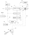
- tractor as an example of an electric working vehicle according to the present invention will be described below.
- the tractor includes left and right front wheels 10, left and right rear wheels 11, and a cover member 12 as a vehicle body traveling device.
- the tractor has a body frame 2 and a driving section 3.
- the body frame 2 is supported by left and right front wheels 10 and left and right rear wheels 11 .
- the cover member 12 is arranged in the front part of the fuselage.
- the operating section 3 is provided behind the cover member 12 .
- the cover member 12 is arranged in front of the driving section 3 .
- the driving section 3 has a protective frame 30, a driver's seat 31, and a steering wheel 32.
- An operator can sit on the driver's seat 31 . This allows the operator to get on the driving section 3 .
- the steering wheel 32 By operating the steering wheel 32, the left and right front wheels 10 are steered. The operator can perform various driving operations in the driving section 3 .
- the tractor is equipped with a running battery 4.
- the cover member 12 is configured to be swingable around an opening/closing axis Q extending in the lateral direction of the machine body. Thereby, the cover member 12 is configured to be openable and closable.
- the driving battery 4 is covered with the cover member 12 when the cover member 12 is in the closed state.
- the tractor includes an inverter 14 and an electric motor M.
- the running battery 4 supplies power to the inverter 14 .
- Inverter 14 converts the DC power from running battery 4 into AC power and supplies it to electric motor M.
- the electric motor M is driven by AC power supplied from the inverter 14 .
- the tractor includes a hydrostatic continuously variable transmission 15 and a transmission 16.
- the hydrostatic continuously variable transmission 15 has a hydraulic pump 15a and a hydraulic motor 15b.
- the hydraulic pump 15a is driven by rotational power from the electric motor M. Rotational power is output from the hydraulic motor 15b by driving the hydraulic pump 15a.
- the hydrostatic continuously variable transmission 15 is configured such that the rotational power is changed between the hydraulic pump 15a and the hydraulic motor 15b.
- the hydrostatic continuously variable transmission 15 is configured so that the gear ratio can be changed steplessly.
- the rotational power output from the hydraulic motor 15b is transmitted to the transmission 16.
- the rotational power transmitted to the transmission 16 is changed in speed by a gear transmission mechanism of the transmission 16 and distributed to the left and right front wheels 10 and the left and right rear wheels 11 .
- the left and right front wheels 10 and the left and right rear wheels 11 are driven.
- the tractor has a mid PTO shaft 17 and a rear PTO shaft 18 as power take-off shafts.
- Rotational power output from the electric motor M is distributed to the hydraulic pump 15a, the mid PTO shaft 17, and the rear PTO shaft 18. Thereby, the mid PTO shaft 17 and the rear PTO shaft 18 rotate.
- a working device as an external device is connected to the mid PTO shaft 17 or the rear PTO shaft 18, the rotational power of the mid PTO shaft 17 or the rear PTO shaft 18 drives the working device.
- a mower 19 is connected to the mid PTO shaft 17 in this embodiment.
- the rotary power of the mid PTO shaft 17 drives the lawn mower 19 .
- the configuration related to control of the electric motor M includes an accelerator device 33 , a control device 34 that controls the operation of the electric motor M, and an inverter 14 .
- the accelerator device 33 is provided near the steering wheel 32 .
- the accelerator device 33 includes a swingable lever and a potentiometer operated by swinging the lever.
- the accelerator device 33 is connected with the control device 34 .
- the control device 34 is connected to the inverter 14 via a signal harness 35 .
- the control device 34 is configured to command the inverter 14 according to the command from the accelerator device 33 .
- the inverter 14 is configured to control the output of the electric motor M by adjusting the electric power supplied from the battery 4 for running to the electric motor M according to a command from the control device 34 .
- the running battery 4 can be charged by an external power supply device KD.
- the tractor is provided with a charging connection portion 37 to which a power supply connector 36 of the power supply device KD can be connected.
- the charging connection portion 37 is provided inside the cover member 12 and is exposed to the outside when the cover member 12 is opened by swinging.
- the control device 34 controls the operation of the electric motor M and also controls the charging state of the power supply device KD.
- the charging connection 37 complies with commonly used standards.
- the running battery 4 is charged through the power supply line 39 while the power supply connector 36 is connected to the charging connection portion 37 .
- the running battery 4 supplies high-voltage (for example, several tens to several hundred volts) electric power to the inverter 14 and the running electric motor M through the power supply line 39 .
- the running battery 4 is configured using, for example, a lithium ion battery, and although not shown, is configured by stacking a large number of low-voltage small unit cells (cells), and the outside is covered with a storage case in a sealed state. It's packed away. Therefore, heat tends to accumulate inside the battery, and when the internal temperature rises, it is difficult for the temperature to drop. Therefore, the running battery 4 is provided with a temperature sensor 40 as temperature detecting means for detecting the internal temperature. Information detected by the temperature sensor 40 is input to the control device 34 .
- the tractor is equipped with an electrical component battery 41 that supplies power to the control device 34 and other electrical components.
- the electrical component battery 41 supplies low voltage (12 volts) power to drive the electrical components.
- the electrical component battery 41 is charged with electric power supplied from the running battery 4 via the DC/DC converter 42 .
- the operating section 3 is provided with a switching operation section 44 as a start command means capable of switching the control device 34 between an operable state and a non-operating state.
- the switching operation unit 44 includes an insertion portion 46 as a mounted portion into which a portable operation key 45 can be inserted, and a push button type switch 47 that can be manually pushed. By pushing the switch 47 while the operation key 45 is inserted into the insertion portion 46, the control device 34 can be switched from the non-operating state to the operable state.
- the operation key 45 functions as a key identifiable only in the work vehicle, like a general vehicle key.
- the operation panel 43 is provided with a meter panel 48 that displays, for example, the vehicle's running state, work state, battery information (charge amount and temperature), and the like.
- the meter panel 48 is connected to the control device 34 and its operation is controlled by the control device 34 .
- the controller 34, the inverter 14, the running battery 4 (including the temperature sensor 40), the DC/DC converter 42, the meter panel 48, the charging connection part 37, etc. are CAN (Controller Area Network) signal harnesses. 35 for data communication.
- the control device 34 communicates with the charging connection portion 37 via the charging communication harness 49, and receives information as to whether or not the power supply connector 36 is connected to the charging connection portion 37, and Information such as the charging current required by the work vehicle is transmitted. Signals are also configured to be communicable between the charging connection portion 37 and the power supply device KD. Further, operation information of the switching operation unit 44 is input to the control device 34 .
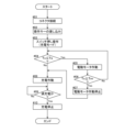
- Control for charging When the control device 34 is switched to the operable state while the power supply connector 36 is connected to the charging connection portion 37, the control device 34 switches to the charging mode. In the charge mode, the power supply device KD is configured to charge the running battery 4 .
- the control device 34 raises the running battery 4 to the target temperature Tm before charging the running battery 4. It is configured to execute temperature increase control to warm the driving battery 4 until the vehicle is stopped.
- control device 34 determines this, it switches to the charging mode (steps #01, #02, #03).
- step #04 it is determined whether or not the internal temperature Tx of the running battery 4 detected by the temperature sensor 40 is equal to or lower than the set temperature Ts (step #04). At this time, if the internal temperature Tx of the running battery 4 is higher than the set temperature Ts, the charging operation is immediately started (step #08). Prior to charging the battery 4 for running, the electric motor M is rotationally driven to warm the battery 4 for running (step #05).
- step #05 corresponds to temperature increase control.
- the power of the electric motor M is transmitted to the hydrostatic continuously variable transmission 15, the mid PTO shaft 17, and the rear PTO shaft 18.
- the electric motor M is rotationally driven. Then, the power of the electric motor M rotates the hydrostatic continuously variable transmission 15 and the power of the electric motor M rotates the mid PTO shaft 17 and the rear PTO shaft 18 .
- step #06 The operation of supplying the driving current to the electric motor M to warm the driving battery 4 continues until the temperature of the driving battery 4 rises above the target temperature Tm (step #06).
- step #07 the operation of the electric motor M is stopped (step #07), and charging of the running battery 4 from the power supply device KD is started (step #08).
- the target temperature Tm may be any temperature at which the suppliable current value allows efficient charging. That is, it may be set to the same temperature as the set temperature Ts, but may be set to a temperature lower than the set temperature Ts or a temperature higher than the set temperature Ts.
- the charging operation is stopped when the driving battery 4 is fully charged (steps #09, #10).
- the hydrostatic continuously variable transmission 15 is rotationally driven by the power of the electric motor M, and the power is transmitted to the mid PTO shaft 17 and the rear PTO shaft 18.
- a configuration may be adopted in which the hydrostatic continuously variable transmission 15 is rotationally driven by the power of the electric motor M and the power is not transmitted to the mid PTO shaft 17 and the rear PTO shaft 18 .
- a configuration may be adopted in which the mid PTO shaft 17 and the rear PTO shaft 18 are rotationally driven and power is not transmitted to the hydrostatic continuously variable transmission 15 .
- the configuration may be such that the electric motor M is rotationally driven, and power is not transmitted to the hydrostatic continuously variable transmission 15, the mid PTO shaft 17, and the rear PTO shaft 18, respectively.
- the electric motor M is rotationally driven for the temperature increase control, but the following configuration may be employed instead of or in addition to this configuration.
- a radiator 50 that cools the coolant flowing through the cooling path provided in the electric motor M and the inverter 14, and a blower fan 51 that blows air to the radiator 50 are provided, and the control device 34 performs temperature rise control.
- the blower fan 51 may be operated to blow the cooling air that has passed through the radiator 50 toward the driving battery 4 .
- This work vehicle is equipped with a cooling mechanism that cools the electric motor M, the inverter 14, the DC/DC converter 42, and the like.
- the cooling mechanism includes a radiator 50, an electric pump 52, and a coolant circulation path 53, as shown in FIG.
- the electric pump 52 circulates the refrigerant, and the refrigerant that has absorbed the heat is cooled by the radiator 50 by the cooling action of the blower fan 51 .
- the wind from the blower fan 51 also acts on the oil cooler 54 .
- the oil cooler 54 cools hydraulic oil for the hydrostatic continuously variable transmission 15 and the like.
- the radiator 50 and the oil cooler 54 are provided in front of the driving battery 4, and the air from the blower fan 51 is configured to flow toward the driving battery 4 after passing through the radiator 50 and the oil cooler 54. It is
- the blower fan 51 When the outside air temperature is low, the blower fan 51 is operated to prevent the temperature of the traveling battery 4 from dropping after the work is performed. The air can be blown toward the driving battery 4, and the heat of the refrigerant can be used to raise the temperature of the driving battery 4.
- the electric motor M is rotationally driven for the temperature increase control.
- 4 may be provided with dedicated heating means (such as a heater), and the heating means may be operated as the temperature increase control.
- the controller 34 is configured to switch to the charging mode when the power supply connector 36 is connected to the charging connector 37 and switched to the operable state.
- the control device 34 may be switched to the operable state in advance and then switched to the charging mode when the power supply connector 36 is connected to the charging connection portion 37 .
- the traveling battery 4 is covered with a storage case in a sealed state on the outside. .
- the present invention is applicable not only to tractors, but also to various electric working vehicles such as rice transplanters, combine harvesters, and construction machinery.
Landscapes
- Engineering & Computer Science (AREA)
- Power Engineering (AREA)
- Mechanical Engineering (AREA)
- Transportation (AREA)
- Chemical & Material Sciences (AREA)
- Chemical Kinetics & Catalysis (AREA)
- Electrochemistry (AREA)
- General Chemical & Material Sciences (AREA)
- Manufacturing & Machinery (AREA)
- Life Sciences & Earth Sciences (AREA)
- Sustainable Development (AREA)
- Sustainable Energy (AREA)
- Automation & Control Theory (AREA)
- Electric Propulsion And Braking For Vehicles (AREA)
- Charge And Discharge Circuits For Batteries Or The Like (AREA)
- Secondary Cells (AREA)
Abstract
Description
以下では、本発明に係る電動作業車の一例としてのトラクタについて説明する。図1に示すように、トラクタは、車体走行装置としての左右の前車輪10及び左右の後車輪11、カバー部材12を備えている。
図4に示すように、電動モータMの制御に係る構成は、アクセル装置33と、電動モータMの作動を制御する制御装置34と、インバータ14と、を備えている。アクセル装置33は、ステアリングホイール32の近傍に備えられている。アクセル装置33は、図示はしないが、揺動操作可能なレバーと、レバーの揺動操作によって操作されるポテンショメータとを備えている。アクセル装置33は制御装置34と接続されている。制御装置34は、信号用ハーネス35を介してインバータ14と接続されている。制御装置34は、アクセル装置33の指令に応じて、インバータ14に指令するように構成されている。インバータ14は、制御装置34の指令に応じて、走行用バッテリー4から電動モータMに供給される電力を調整して電動モータMの出力を制御するように構成されている。
図4に示すように、走行用バッテリー4は外部の給電装置KDにより充電可能である。トラクタには、給電装置KDの給電用コネクタ36が接続可能な充電用接続部37が備えられている。充電用接続部37は、カバー部材12の内部に備えられ、カバー部材12を揺動開放すると、外方に露出する。制御装置34は、電動モータMの作動を制御するとともに、給電装置KDによる充電状態を制御する。
制御装置34は、給電用コネクタ36が充電用接続部37に接続されている状態で、動作可能状態に切り換えられると、充電モードに切り換わる。そして、充電モードにおいて、給電装置KDにより走行用バッテリー4への充電を行うように構成されている。
(1)上記実施形態では、昇温制御において、電動モータMの動力により静油圧式無段変速装置15を回転駆動させ、且つ、ミッドPTO軸17及びリヤPTO軸18に動力を伝達する構成としたが、この構成に代えて、電動モータMの動力により静油圧式無段変速装置15を回転駆動させ、且つ、ミッドPTO軸17及びリヤPTO軸18に動力を伝達しない構成としてもよい。又、ミッドPTO軸17及びリヤPTO軸18を回転駆動させ、且つ、静油圧式無段変速装置15に動力を伝達しない構成としてもよい。さらに、電動モータMを回転駆動させる構成とし、静油圧式無段変速装置15、ミッドPTO軸17及びリヤPTO軸18の夫々に動力を伝達しない構成としてもよい。
10 前車輪(車体走行装置)
11 後車輪(車体走行装置)
14 インバータ
17 ミッドPTO軸(動力取り出し軸)
18 リヤPTO軸(動力取り出し軸)
34 制御装置
37 接続部
50 ラジエータ
51 送風ファン
M 電動モータ
Claims (5)
- 車体を走行駆動可能な電動モータと、
前記電動モータに駆動用電力を供給するとともに、外部の給電装置により充電可能なバッテリーと、
前記給電装置側の給電用コネクタが接続可能な接続部と、
前記給電装置による充電状態を制御する制御装置と、
前記バッテリーの温度を検出する温度検出手段と、が備えられ、
前記制御装置は、前記温度検出手段にて検出される前記バッテリーの温度が設定温度以下であれば、前記バッテリーに対する充電に先立って、前記バッテリーが目標温度に上昇するまで前記バッテリーを温める昇温制御を実行するように構成されている電動作業車。 - 前記制御装置が、前記昇温制御として、前記電動モータを回転駆動させる請求項1に記載の電動作業車。
- 前記電動モータの動力により駆動され、外部装置に動力を出力可能な動力取出し軸が備えられ、
前記制御装置が、前記昇温制御として、前記電動モータの動力により前記動力取出し軸を回転駆動させる請求項2に記載の電動作業車。 - 前記電動モータの動力を変速して車体走行装置に伝達する静油圧式無段変速装置が備えられ、
前記制御装置が、前記昇温制御として、前記電動モータの動力により前記静油圧式無段変速装置を作動させる請求項2又は3に記載の電動作業車。 - 前記バッテリーからの直流電力を交流電力に変換して前記電動モータに供給するインバータと、
前記電動モータ及び前記インバータに設けられた冷却用経路を通して通流する冷媒を冷却するラジエータと、
前記ラジエータに送風する送風ファンと、が備えられ、
前記制御装置が、前記昇温制御として、前記送風ファンを作動させて、前記ラジエータを通過した冷却風を前記バッテリーに向けて通風させる請求項1から4のいずれか1項に記載の電動作業車。
Priority Applications (3)
| Application Number | Priority Date | Filing Date | Title |
|---|---|---|---|
| EP22924940.4A EP4475385A4 (en) | 2022-02-03 | 2022-10-31 | ELECTRIC CONSTRUCTION VEHICLE |
| CN202280090757.7A CN118786604A (zh) | 2022-02-03 | 2022-10-31 | 电动作业车 |
| US18/786,665 US20240383377A1 (en) | 2022-02-03 | 2024-07-29 | Electric work vehicle |
Applications Claiming Priority (2)
| Application Number | Priority Date | Filing Date | Title |
|---|---|---|---|
| JP2022015811A JP7699555B2 (ja) | 2022-02-03 | 2022-02-03 | 電動作業車 |
| JP2022-015811 | 2022-02-03 |
Related Child Applications (1)
| Application Number | Title | Priority Date | Filing Date |
|---|---|---|---|
| US18/786,665 Continuation US20240383377A1 (en) | 2022-02-03 | 2024-07-29 | Electric work vehicle |
Publications (1)
| Publication Number | Publication Date |
|---|---|
| WO2023149035A1 true WO2023149035A1 (ja) | 2023-08-10 |
Family
ID=87552138
Family Applications (1)
| Application Number | Title | Priority Date | Filing Date |
|---|---|---|---|
| PCT/JP2022/040738 Ceased WO2023149035A1 (ja) | 2022-02-03 | 2022-10-31 | 電動作業車 |
Country Status (5)
| Country | Link |
|---|---|
| US (1) | US20240383377A1 (ja) |
| EP (1) | EP4475385A4 (ja) |
| JP (1) | JP7699555B2 (ja) |
| CN (1) | CN118786604A (ja) |
| WO (1) | WO2023149035A1 (ja) |
Families Citing this family (4)
| Publication number | Priority date | Publication date | Assignee | Title |
|---|---|---|---|---|
| AU2023424346A1 (en) * | 2023-01-17 | 2025-06-19 | Nanjing Chervon Industry Co., Ltd. | Riding lawn mower |
| JP2025079593A (ja) * | 2023-11-10 | 2025-05-22 | 株式会社クボタ | 電動作業車 |
| WO2025142398A1 (ja) * | 2023-12-27 | 2025-07-03 | 株式会社クボタ | 電動作業車両 |
| WO2025215739A1 (ja) * | 2024-04-09 | 2025-10-16 | 日産自動車株式会社 | 電動車両制御方法及び電動車両制御装置 |
Citations (6)
| Publication number | Priority date | Publication date | Assignee | Title |
|---|---|---|---|---|
| JP2010127271A (ja) * | 2008-12-01 | 2010-06-10 | Sumitomo Heavy Ind Ltd | ハイブリッド式建設機械の暖機方法 |
| JP2011015544A (ja) * | 2009-07-02 | 2011-01-20 | Honda Motor Co Ltd | 電動車両 |
| JP2014510996A (ja) * | 2011-02-24 | 2014-05-01 | ツェットエフ、フリードリッヒスハーフェン、アクチエンゲゼルシャフト | 車両用駆動バッテリーの加温方法及び装置 |
| JP2016159789A (ja) * | 2015-03-03 | 2016-09-05 | 日立建機株式会社 | ハイブリッド式建設機械 |
| JP2020082865A (ja) * | 2018-11-19 | 2020-06-04 | 株式会社小松製作所 | 作業車両、作業車両の制御装置および制御方法 |
| JP2021000957A (ja) | 2019-06-24 | 2021-01-07 | 株式会社クボタ | 電動作業車 |
Family Cites Families (1)
| Publication number | Priority date | Publication date | Assignee | Title |
|---|---|---|---|---|
| US12081062B2 (en) * | 2019-11-08 | 2024-09-03 | Oshkosh Corporation | Power system for a vehicle |
-
2022
- 2022-02-03 JP JP2022015811A patent/JP7699555B2/ja active Active
- 2022-10-31 WO PCT/JP2022/040738 patent/WO2023149035A1/ja not_active Ceased
- 2022-10-31 CN CN202280090757.7A patent/CN118786604A/zh active Pending
- 2022-10-31 EP EP22924940.4A patent/EP4475385A4/en active Pending
-
2024
- 2024-07-29 US US18/786,665 patent/US20240383377A1/en active Pending
Patent Citations (6)
| Publication number | Priority date | Publication date | Assignee | Title |
|---|---|---|---|---|
| JP2010127271A (ja) * | 2008-12-01 | 2010-06-10 | Sumitomo Heavy Ind Ltd | ハイブリッド式建設機械の暖機方法 |
| JP2011015544A (ja) * | 2009-07-02 | 2011-01-20 | Honda Motor Co Ltd | 電動車両 |
| JP2014510996A (ja) * | 2011-02-24 | 2014-05-01 | ツェットエフ、フリードリッヒスハーフェン、アクチエンゲゼルシャフト | 車両用駆動バッテリーの加温方法及び装置 |
| JP2016159789A (ja) * | 2015-03-03 | 2016-09-05 | 日立建機株式会社 | ハイブリッド式建設機械 |
| JP2020082865A (ja) * | 2018-11-19 | 2020-06-04 | 株式会社小松製作所 | 作業車両、作業車両の制御装置および制御方法 |
| JP2021000957A (ja) | 2019-06-24 | 2021-01-07 | 株式会社クボタ | 電動作業車 |
Non-Patent Citations (1)
| Title |
|---|
| See also references of EP4475385A4 |
Also Published As
| Publication number | Publication date |
|---|---|
| JP2023113437A (ja) | 2023-08-16 |
| CN118786604A (zh) | 2024-10-15 |
| EP4475385A1 (en) | 2024-12-11 |
| JP7699555B2 (ja) | 2025-06-27 |
| US20240383377A1 (en) | 2024-11-21 |
| EP4475385A4 (en) | 2026-01-21 |
Similar Documents
| Publication | Publication Date | Title |
|---|---|---|
| WO2023149035A1 (ja) | 電動作業車 | |
| US20160347198A1 (en) | Battery pack thermal management | |
| US20170284062A1 (en) | Hybrid Construction Machine | |
| JP2021099086A (ja) | 作業機 | |
| US9728826B2 (en) | Traction battery thermal management method and system | |
| CN100519248C (zh) | 用于电动车辆的电存储装置的冷却设备和冷却方法 | |
| US10153523B2 (en) | Traction battery thermal management method and system | |
| JP7833034B2 (ja) | 作業車両、作業車両の制御装置および制御方法 | |
| US20150097041A1 (en) | Vehicle comprising air conditioning apparatus | |
| US20230210051A1 (en) | Battery management system and method for electric mower | |
| WO2011089726A1 (ja) | 電気駆動式車両 | |
| JP7825667B2 (ja) | 電動作業車 | |
| JP7072498B2 (ja) | 電動作業車 | |
| JP2024120921A5 (ja) | ||
| US20240399927A1 (en) | Electric work vehicle | |
| WO2023149026A1 (ja) | 電動作業車 | |
| JP7507742B2 (ja) | 電動作業車 | |
| JPH11273983A (ja) | キャパシタ冷却装置 | |
| JP7796612B2 (ja) | 電動作業車、及び、充電方法 | |
| JP7519984B2 (ja) | 電動作業車 | |
| KR100792915B1 (ko) | 하이브리드 전기 차량용 고전압 배터리 냉각 장치 및 방법 | |
| WO2025100139A1 (ja) | 電動作業車 | |
| WO2025142398A1 (ja) | 電動作業車両 | |
| WO2023127363A1 (ja) | 電動作業車 | |
| JP2024115893A (ja) | 電動作業車 |
Legal Events
| Date | Code | Title | Description |
|---|---|---|---|
| 121 | Ep: the epo has been informed by wipo that ep was designated in this application |
Ref document number: 22924940 Country of ref document: EP Kind code of ref document: A1 |
|
| WWE | Wipo information: entry into national phase |
Ref document number: 202280090757.7 Country of ref document: CN |
|
| WWE | Wipo information: entry into national phase |
Ref document number: 202417062322 Country of ref document: IN |
|
| WWE | Wipo information: entry into national phase |
Ref document number: 2022924940 Country of ref document: EP |
|
| NENP | Non-entry into the national phase |
Ref country code: DE |
|
| ENP | Entry into the national phase |
Ref document number: 2022924940 Country of ref document: EP Effective date: 20240903 |