WO2023149082A1 - 電流センサ - Google Patents
電流センサ Download PDFInfo
- Publication number
- WO2023149082A1 WO2023149082A1 PCT/JP2022/045525 JP2022045525W WO2023149082A1 WO 2023149082 A1 WO2023149082 A1 WO 2023149082A1 JP 2022045525 W JP2022045525 W JP 2022045525W WO 2023149082 A1 WO2023149082 A1 WO 2023149082A1
- Authority
- WO
- WIPO (PCT)
- Prior art keywords
- current
- small
- current unit
- units
- plane
- Prior art date
- Legal status (The legal status is an assumption and is not a legal conclusion. Google has not performed a legal analysis and makes no representation as to the accuracy of the status listed.)
- Ceased
Links
Images


Classifications
-
- G—PHYSICS
- G01—MEASURING; TESTING
- G01R—MEASURING ELECTRIC VARIABLES; MEASURING MAGNETIC VARIABLES
- G01R19/00—Arrangements for measuring currents or voltages or for indicating presence or sign thereof
- G01R19/0092—Measuring current only
-
- G—PHYSICS
- G01—MEASURING; TESTING
- G01R—MEASURING ELECTRIC VARIABLES; MEASURING MAGNETIC VARIABLES
- G01R1/00—Details of instruments or arrangements of the types included in groups G01R5/00 - G01R13/00 and G01R31/00
- G01R1/02—General constructional details
- G01R1/06—Measuring leads; Measuring probes
- G01R1/067—Measuring probes
- G01R1/07—Non contact-making probes
-
- G—PHYSICS
- G01—MEASURING; TESTING
- G01R—MEASURING ELECTRIC VARIABLES; MEASURING MAGNETIC VARIABLES
- G01R1/00—Details of instruments or arrangements of the types included in groups G01R5/00 - G01R13/00 and G01R31/00
- G01R1/02—General constructional details
- G01R1/18—Screening arrangements against electric or magnetic fields, e.g. against earth's field
-
- G—PHYSICS
- G01—MEASURING; TESTING
- G01R—MEASURING ELECTRIC VARIABLES; MEASURING MAGNETIC VARIABLES
- G01R15/00—Details of measuring arrangements of the types provided for in groups G01R17/00 - G01R29/00, G01R33/00 - G01R33/26 or G01R35/00
- G01R15/14—Adaptations providing voltage or current isolation, e.g. for high-voltage or high-current networks
- G01R15/20—Adaptations providing voltage or current isolation, e.g. for high-voltage or high-current networks using galvano-magnetic devices, e.g. Hall-effect devices, i.e. measuring a magnetic field via the interaction between a current and a magnetic field, e.g. magneto resistive or Hall effect devices
- G01R15/205—Adaptations providing voltage or current isolation, e.g. for high-voltage or high-current networks using galvano-magnetic devices, e.g. Hall-effect devices, i.e. measuring a magnetic field via the interaction between a current and a magnetic field, e.g. magneto resistive or Hall effect devices using magneto-resistance devices, e.g. field plates
-
- G—PHYSICS
- G01—MEASURING; TESTING
- G01R—MEASURING ELECTRIC VARIABLES; MEASURING MAGNETIC VARIABLES
- G01R15/00—Details of measuring arrangements of the types provided for in groups G01R17/00 - G01R29/00, G01R33/00 - G01R33/26 or G01R35/00
- G01R15/14—Adaptations providing voltage or current isolation, e.g. for high-voltage or high-current networks
- G01R15/20—Adaptations providing voltage or current isolation, e.g. for high-voltage or high-current networks using galvano-magnetic devices, e.g. Hall-effect devices, i.e. measuring a magnetic field via the interaction between a current and a magnetic field, e.g. magneto resistive or Hall effect devices
- G01R15/207—Constructional details independent of the type of device used
Definitions
- the present invention relates to a current sensor that measures a current to be measured flowing through a busbar based on magnetism.
- the detection unit to which the large current is applied may fall outside the measurement range of the magnetic sensor, magnetic saturation of the shield provided in the detection unit, or other detection units may fail. Problems such as errors may occur due to influences and the like.
- Patent Document 1 discloses a current sensor that detects magnetism generated by a current, with the aim of providing a current sensor capable of obtaining a wide dynamic range of input current. It is described that a plurality of them are provided.
- An object of the present invention is to provide a current sensor in which a large current unit through which a large current flows and a small current unit through which a small current flows are integrated.
- An object of the present invention is to provide a current sensor in which measurement errors due to the influence of a detection unit are suppressed.
- the present invention has the following configurations as means for solving the above-described problems.
- a flat bus bar through which current flows and extending in a first direction, a magnetic sensor arranged to face one plate surface of the bus bar, and a magnetic sensor arranged to face the other plate surface of the bus bar
- a current sensor comprising a plurality of units each having a shield with a flat plate-like base, wherein the plurality of units are integrally formed, wherein the plurality of units is a large current in which a relatively large current flows through the bus bar. and a small-current unit in which a relatively small current flows through the bus bar, and the normal direction of the plate surface of the bus bar is set in the second direction, the first direction, and the second direction.
- a first distance between the busbar and the magnetic sensor in the second direction is the same between the large-current unit and the small-current unit when the orthogonal direction is the third direction.
- a second distance between the bus bar and the base in the second direction is larger in the large-current unit than in the small-current unit.
- the large-current unit and the small-current unit may have the same bus bar, magnetic sensor, and shield. By using common members in the large-current unit and the small-current unit, the manufacturing cost of the current sensor can be suppressed.
- the shield may have, at both ends of the base in the third direction, standing portions extending toward the side in the second direction on which the bus bar and the magnetic sensor are arranged. Also, an end portion of the shield may be positioned between the magnetic sensor and the busbar in the second direction.
- the bus bars of the small current units are arranged on a plane B, the plane A and the plane B are the same plane, the interval b is larger than the interval a1,
- the interval b may be larger than the interval a2.
- the busbars of the small current units are arranged on a plane B, the plane A and the plane B are different planes, and the interval b is equal to or greater than the interval a1.
- the interval b may be equal to or greater than the interval a2.
- the magnetism caused by the current flowing through the busbars of the large-current units causes the large-current Influence on the small current unit adjacent to the current unit can be suppressed. If plane A and plane B are the same plane, the size of the current sensor in the second direction can be reduced, and if plane A and plane B are different planes, the size of the current sensor in the third direction can be reduced. size can be reduced.
- the adjacent units are arranged on the same straight line extending in the third direction.
- the adjacent units may not be arranged on the same straight line extending in the third direction.
- the bus bars of the small current unit group are arranged on a plane A
- the bus bars of the small current units are arranged on a plane B
- the plane A and the plane B are the same plane
- the large In the current unit group adjacent large current units are not arranged on the same straight line extending in the third direction
- adjacent small current units are arranged in the third direction.
- the large-current unit and the small-current unit may be arranged on the same straight line extending in the third direction instead of being arranged on the same straight line extending in the third direction.
- the busbars of the small-current units are arranged on a plane B
- the plane A and the plane B are the same plane
- the adjacent small-current units in the small-current unit group are arranged on the plane B.
- the adjacent large current unit and the small current unit may be arranged on the same straight line extending in the third direction.
- It may further include a medium-current unit through which a current value between the current value of the current flowing through the large-current unit and the current value of the current flowing through the small-current unit flows.
- FIG. 2 is a plan view schematically showing main parts of the current sensor according to the first embodiment
- FIG. 2 is a cross-sectional view schematically showing main parts of the current sensor according to the first embodiment
- FIG. 11 is a plan view schematically showing a main part of a current sensor according to a modification
- FIG. 10 is a cross-sectional view schematically showing a main part of a current sensor according to a modification
- FIG. 7 is a cross-sectional view schematically showing the positional relationship of the main parts of the current sensor unit according to the second embodiment
- FIG. 11 is a cross-sectional view schematically showing the positional relationship of main parts in a current sensor unit according to a modification
- FIG. 10 is a plan view schematically showing the positional relationship of the main parts in the current sensor unit according to the third embodiment
- FIG. 11 is a cross-sectional view schematically showing the positional relationship of the main parts in the current sensor unit according to the third embodiment
- FIG. 11 is a plan view schematically showing the positional relationship of main parts in a current sensor unit according to a modification
- FIG. 11 is a cross-sectional view schematically showing the positional relationship of main parts in a current sensor unit according to a modification
- FIG. 11 is a plan view schematically showing the positional relationship of main parts in a current sensor unit according to a modification
- FIG. 11 is a plan view schematically showing the positional relationship of main parts in a current sensor unit according to a modification
- FIG. 11 is a plan view schematically showing the positional relationship of main parts in a current sensor unit according to a modification
- FIG. 11 is a cross-sectional view schematically showing the positional relationship of main parts in a current sensor unit according to a modification; 4 is a cross-sectional view showing the positional relationship and current values of the main parts of the current sensor unit of Example 1.
- FIG. 4 is a cross-sectional view showing the positional relationship and current values of the main parts of the current sensor unit of Example 1.
- FIG. 4 is a cross-sectional view showing the positional relationship and current values of the main parts of the current sensor unit of Example 1.
- FIG. 4 is a graph showing the results of Example 1.
- FIG. FIG. 11 is a plan view schematically showing the positional relationship of the main parts in the current sensor unit of Example 3;
- FIGS. 1A and 1B are a plan view and a cross-sectional view schematically showing main parts of a current sensor 10 according to this embodiment.
- the current sensor 10 includes a plurality of units 11, and the plurality of units 11 are integrally formed.
- Each of the units 11 has a busbar 12 , a magnetic sensor 13 and a shield 14 .
- the extending direction (first direction) of the busbar 12 is the X-axis direction
- the normal direction (second direction) of the plate surfaces 12a and 12b of the busbar 12 is the Y-axis direction
- the first and second directions are the directions.
- the orthogonal direction (third direction) be the Z-axis direction.
- the busbar 12 has a flat plate shape and extends in the first direction (X-axis direction), through which current to be detected flows, and is made of copper, brass, aluminum, or the like. Note that the bus bar 12 does not have to be bent into a flat plate shape at locations other than the location facing the magnetic sensor 13 and the shield 14 .
- the magnetic sensor 13 is arranged to face one plate surface 12a (on the Y-axis direction Y1 side) of the busbar 12, is mounted on a substrate (not shown), and detects magnetism caused by the current to be measured flowing through the busbar 12. do.
- a magnetoresistive effect element such as a GMR element or a TMR element using a magnetoresistive effect whose electric resistance changes with an external magnetic field is used.
- the shield 14 has a plate-like base portion 14a arranged to face the plate surface 12b on the other side (the Y2 side in the Y-axis direction) of the busbar 12 .
- the shield 14 also has standing portions 14b extending from both ends 14c of the base portion 14a in the third direction (Z-axis direction) to one side in the second direction (Y-axis direction).
- the one side in the second direction is the side on which the bus bar 12 and the magnetic sensor 13 are arranged as viewed from the base portion 14 a when the shield 14 is incorporated as the unit 11 .
- Shield 14 suppresses electromagnetic interference caused by busbar 12 .
- the shield 14 is configured by stacking a plurality of metal plate bodies having the same shape.
- the plurality of units 11 includes a large current unit 11A through which a relatively large current flows through the busbar 12 and a small current unit 11B through which a relatively small current flows through the busbar 12.
- a large current unit 11A through which a relatively large current flows through the busbar 12
- a small current unit 11B through which a relatively small current flows through the busbar 12.
- the same bus bar 12, magnetic sensor 13 and shield 14 are used in the large current unit 11A and the small current unit 11B of the current sensor 10.
- FIG. By using the same member for each unit 11, the manufacturing cost of the current sensor 10 can be suppressed.
- the same bus bar 12 means that the portions overlapping the magnetic sensor 13 and the shield 14 in the second direction (Y-axis direction) are the same. Therefore, the busbars 12 may have different lengths and end shapes in the first direction (X-axis direction).
- the distance (first distance) L1 between the bus bar 12 and the magnetic sensor 13 in the second direction is the same as the distance L1A in the large current unit 11A and the distance L1B in the small current unit 11B.
- the distance L2A in the large-current unit 11A is longer than the distance L2B in the small-current unit 11B. is also big.
- the distance (third distance) L3 between the end portion 14e of the shield 14 (upright portion 14b) and the magnetic sensor 13 in the second direction is greater than the distance L3A in the large current unit 11A. longer than the distance L3B in the display unit 11B.
- the distance L3A is 0 in FIG. 1A.
- the distances L1, L2 and L3 between the members refer to the distances between the centers of the members in the second direction.
- the shield 14 also functions as a yoke for magnetism (induced magnetic field) generated by the current flowing through the busbar 12 , and the magnetism emitted from the end 14 e of the shield 14 is measured by the magnetic sensor 13 . Therefore, the magnitude of the magnetism caused by the current of the busbar 12 measured by the magnetic sensor 13 can be adjusted by the distance L2 and the distance L3. That is, by increasing the distance L2 and the distance L3, the effect of the shield 14 that enhances the magnetism due to the current of the busbar 12 can be suppressed, and the magnetism reaching the magnetic sensor 13 can be reduced.
- the shield 14 for the large current unit 11A and the shield 14 for the small current unit 11B have different shapes, a difference is provided between the distance L2 and the distance L3 between the large current unit 11A and the small current unit 11B. be able to.
- the shield 14 for the large-current unit 11A and the shield 14 for the small-current unit 11B are composed of the same parts.
- the distance L3 between the magnetic sensor 13 and the end portion 14e of the shield 14 also differs. You can have different effects. If the distance L2 is increased, the distance L3 is increased, so that the effect of increasing the magnetism of the shield 14 in the high-current unit 11A can be suppressed. By increasing the distance L2 and the distance L3, the magnetism reaching the magnetic sensor 13 when a large current flows through the bus bar 12 can be reduced. Therefore, it is possible to widen the range of the current flowing through the bus bar 12 that can be measured by the large current unit 11A.
- the shield 14 absorbs the magnetism generated by the current flowing through the busbar 12. can be enhanced.
- the position of the end portion 14e between the magnetic sensor 13 and the busbar 12 in the second direction means that the end portion 14e is located between the center point of the magnetic sensor 13 and the center point of the busbar 12 in the second direction.
- the ends 14e of the shield 14 are not the ends 14c on both sides of the shield 14 in the Z-axis direction, but the Y1-side ends of the standing portions 14b in the Y-axis direction.
- the distance L3A of the large current unit 11A is longer than the distance L3B of the small current unit 11B.
- the effect of enhancing the magnetism generated by the current flowing through the bus bar 12 is differentiated between the large-current unit 11A and the small-current unit 11B.
- FIG. 2A is a plan view schematically showing main parts of a current sensor 20 according to a modification
- FIG. 2B is a cross-sectional view.
- the large-current unit 21A and the small-current unit 21B (unit 21) of the current sensor 20 are replaced with the shield 14 having the erected portion 14b, and are made of a flat plate-like structure consisting only of the base portion 24a.
- a shield 24 is provided.
- current sensor 20 differs from current sensor 10 .
- each unit 21 has a flat shield 24 instead of the U-shaped shield 14 in the YZ plane cross section.
- the distance L1 between the bus bar 12 and the magnetic sensor 13 in the second direction is the same as the distance L1A in the large current unit 21A and the distance L1B in the small current unit 21B.
- the distance L2 between the bus bar 12 and the base portion 24a of the shield 24 in the second direction the distance L2A in the large-current unit 21A is longer than the distance L2B in the small-current unit 21B.
- the distance L3A in the large current unit 21A is longer than the distance L3B in the small current unit 21B.
- each unit 21 shows the configuration of each unit 21 in which the shield 24 is arranged on the opposite side of the magnetic sensor 13 with the bus bar 12 interposed therebetween.
- the configuration may be such that the bus bar 12 and the magnetic sensor 13 are arranged between a pair of shields 24 arranged as above.
- FIG. 3 is a cross-sectional view schematically showing the positional relationship of main parts of the current sensor 30.
- the current sensor 30 has a large-current unit group 31 and a small-current unit group 32 that are arranged adjacent to each other in the third direction.
- a plurality of large-current units 11A are arranged at intervals a1 in the third direction (Z-axis direction).
- a plurality of small-current units 11B are arranged at intervals a2 in the third direction.
- the large current unit 11A and the small current unit 11B that are adjacent to each other, that is, the small current unit group 32 arranged next to each other among the plurality of large current units 11A that constitute the large current unit group 31 is the most
- the large-current unit 11A arranged in the close position and the large-current unit group 31 arranged next to each other among the plurality of small-current units 11B constituting the small-current unit group 32 are arranged in the closest position.
- the low-current unit 11B are arranged in the third direction with an interval b.
- the large-current unit 11A arranged closest to the Z1 side end in the Z-axis direction which is the third direction in FIG. 3
- the small-current unit 11B arranged closest to the Z2 side end in the Z-axis direction are arranged at intervals b in the third direction.
- the interval refers to the distance between the center points of the units 11 arranged adjacent to each other in the third direction.
- the busbars 12 of the large-current unit 11A are arranged on the plane A.
- the busbars 12 of the small-current units 11B are arranged on the plane B.
- the plane A and the plane B are the same plane, and both are located on the XZ plane.
- Each of the large-current unit group 31 and the small-current unit group 32 shown in FIG. 3 includes three large-current units 11A and three small-current units 11B. may
- the interval b between the adjacent large current unit 11A and small current unit 11B is larger than the interval a1 between the large current unit 11A and larger than the interval a2 between the small current unit 11B. That is, the interval b between the large-current unit 11A and the small-current unit 11B, which are adjacent to each other across the boundary between the large-current unit group 31 and the small-current unit group 32, is the interval between the units 11 belonging to the same unit group. It is wider than a1 and a2. With this configuration, it is possible to suppress the influence of the magnetism generated by the current flowing through the busbars 12 of the adjacent units 11 belonging to different unit groups on the magnetic sensors 13 of the other units 11 .
- the influence of the adjacent unit 11, particularly the influence of the magnetism caused by the current flowing through the bus bar 12 of the large current unit 11A, on the magnetic sensor 13 of the adjacent small current unit 11B is suppressed, and the current is detected. Error can be reduced.
- FIG. 4 is a cross-sectional view schematically showing the positional relationship of main parts in a current sensor 40 according to a modification.
- the current sensor 40 has a large current unit group 31 and a small current unit group 32 .
- the relationship is the same as for current sensor 30 . It differs from the current sensor 30 in that the plane A on which the busbars 12 of the large current unit 11A are arranged and the plane B on which the busbars 12 of the small current unit 11B are arranged are different planes. .
- the interval b is larger than both the interval a1 and the interval a2.
- spacing b may be equal to either or both of spacing a1 and spacing a2.
- the positions of the plane A and the plane B in the Y-axis direction may be reversed from those in FIG.
- the plane A on which the busbars 12 of the large-current unit 11A are arranged in the Y-axis direction is different from the plane B on which the busbars 12 of the small-current unit 11B are arranged. It is preferably located on the side (Y2 side) opposite to the magnetic sensor 13 of 11B.
- FIG. 5A is a plan view schematically showing the positional relationship of main parts in a current sensor 50 according to the third embodiment
- FIG. 5B is a cross-sectional view.
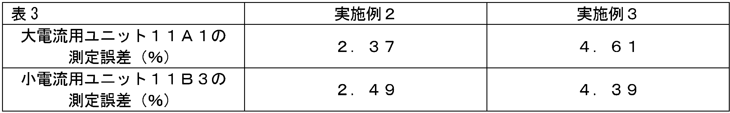
- the large current units 11A are designated as 11A1, 11A2 and 11A3
- the small current units 11B are designated as 11B1, 11B2 and 11B3 from the Z1 side to the Z2 side in the Z axis direction. shown as
- the adjacent large-current units 11A1 and 11A2, and the adjacent large-current units 11A2 and 11A3 are all aligned on the same straight line. Not placed above.
- the same straight line is a straight line parallel to the Z-axis direction (third direction).
- the large-current units 11A1 and 11A3 on both sides are arranged on a straight line C parallel to the Z-axis, and the large-current unit 11A2 arranged between the large-current units 11A1 and 11A3 is arranged parallel to the straight line C. It is arranged on the straight line D.
- the small current units 11B1, 11B2 and 11B3 arranged side by side in the Z-axis direction are also not arranged on the same straight line between the adjacent small current units 11B1 and 11B2 and the adjacent small current units 11B2 and 11B3. .
- the small current units 11B1 and 11B3 on both sides are arranged on a straight line C parallel to the Z axis, and the small current unit 11B2 between them is arranged on a straight line D parallel to the straight line C.
- both the large-current unit group 51 and the small-current unit group 52 when the magnitude of the current flowing through the busbars 12 of the adjacent units 11 is the same, the adjacent units 11 are arranged on the same straight line extending in the Z-axis direction. Not placed. With this configuration, it is possible to reduce the size of the large-current unit group 51 and the small-current unit group 52 in the Z-axis direction.
- the large-current unit group 51 and the small-current unit group 52 can be reduced in size in the Z-axis direction and also in the X-axis direction.
- the large-current unit 11A1 and the small-current unit 11B3 are adjacent units 11 with different magnitudes of currents flowing through the busbars 12, and are arranged on the same straight line C extending in the Z-axis direction.
- the shield 14 (upright portion 14b) of the large current unit 11A1 and the small current unit 11B3 is positioned. ) are doubled. Therefore, the shield 14 can suppress the influence of the magnetism caused by the current flowing through the busbar 12 of the large-current unit 11A1 on the magnetic sensor 13 of the small-current unit 11B3.
- the shield 14 is a plate-like one composed only of the base portion 14a without the standing portion 14b
- the bus bar 12 and the magnetic sensor 13 are arranged between the pair of shields 24 (base portions 14a).
- the busbars 12 of the large current units 11A1, 11A2 and 11A3 of the large current unit group 51 are arranged on a plane A parallel to the XZ plane.
- the busbars 12 of the small current units 11B1, 11B2 and 11B3 of the small current unit group 52 are arranged on a plane B parallel to the XZ plane.
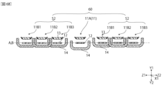
- FIG. 6A is a plan view schematically showing the positional relationship of main parts in a current sensor 60 according to a modification
- 6B is a cross-sectional view.
- the current sensor 60 differs from the current sensor 50 in that it has a large-current unit 11A instead of the large-current unit group 51 .
- the small-current unit 11B3 and the small-current unit 11B1 and the large-current unit 11A adjacent in the Z1 direction are arranged on the same straight line C extending in the Z-axis direction.
- FIG. 7A is a plan view schematically showing the positional relationship of main parts in a current sensor 70 according to another modification
- FIG. 7B is a cross-sectional view.
- the current sensor 70 differs from the current sensor 50 of FIG. 5 in that it further includes a medium-current unit group 53 between the large-current unit group 51 and the small-current unit group 52 .
- the medium-current unit group 53 includes the medium-current unit 11C through which the current value is between the current value of the current flowing through the large-current unit 11A and the current value of the current flowing through the small-current unit 11B.
- the medium-current unit group 53 is provided to widen the range of current that can be measured.
- a current sensor 70 with a may be more suitable.
- the medium-current unit 11C includes a busbar 12, a magnetic sensor 13 and a shield 14, like the large-current unit 11A and the small-current unit 11B.
- the relative positional relationship of each member constituting the medium-current unit 11C is also the same as that of the large-current unit 11A and the small-current unit 11B.
- the medium-current unit 11C has the same distance L1 (see FIG. 1B) between the busbar 12 and the magnetic sensor 13 in the Y-axis direction as the large-current unit 11A and the small-current unit 11B.
- the distance L2 (see FIG. 1B) between the busbar 12 and the shield 14 in the Y-axis direction is smaller than the large current unit 11A and larger than the small current unit 11B.
- the units 11 having different current values of the current flowing through the busbars 12 are arranged on the same straight line extending in the Z-axis direction. That is, the large-current unit 11A and the medium-current unit 11C adjacent in the Z-axis direction are arranged on the same straight line C, and the small-current unit 11B and the medium-current unit 11C adjacent in the Z-axis direction are arranged on the same line. Place on straight line C.
- the shield 14 can suppress the influence of magnetism generated by a relatively large current flowing through the bus bar 12 of the adjacent unit 11 on the magnetic sensor 13 that measures a relatively small current. Therefore, the current sensor 70 can be made with less measurement error.
- Example 1 Regarding the unit 11 having the configuration shown in FIGS. Effects on the detected magnetic flux density and the magnetic flux density in the shield 14 were measured.
- Example 1 the shield 14 having a U-shaped cross section and having the standing portion 14b was used.
- the distance L1 was set to 2.6 mm and the distance L2 was set to the size shown in Table 2.
- Currents of different magnitudes were passed through the bus bar 12 of the unit and measurements were performed.
- Comparative Example 1 a unit having a distance L1 of 2.6 mm and a distance L2 of 1.2 mm was also measured in the same manner as in Example 1.
- Table 2 shows the results of the measured and detected magnetic flux densities and the in-shield magnetic flux densities for Example 1 and Comparative Example 1.
- the ability of the shield 14 to collect the magnetism generated by the busbar 12 is adjusted, the magnetic flux density in the shield 14 is suppressed, and the shield 14 is magnetically saturated. I was able to prevent it from happening.
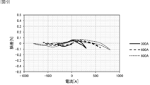
- FIG. 9 is a graph showing the measurement results obtained by changing the direction of the current to be measured flowing in the bus bar 12 in Example 1.
- FIG. 9 As shown in the figure, the errors in the measured current values were the same regardless of the magnitude of the detected current.
- Example 2 For the current sensor 50 shown in FIG. 5A, the measurement error caused by the current flowing through the bus bar 12 of the adjacent unit 11 was measured.
- the large-current unit group 51 and the small-current unit group 52 those having the following configurations were used.
- Large current unit group 51 Current: 800A Distance L1: 2.6 mm, Distance L2: 3.5 mm (see FIG. 1B) Spacing a1: 12.5 mm (see Fig. 3)
- Small current unit group 52 Current: 300A Distance L1: 2.6 mm, Distance L2: 1.2 mm (see FIG.
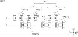
- Example 3 For the current sensor 80 shown in FIG. 10, the measurement error caused by the current flowing through the bus bar 12 of the adjacent unit 11 was measured.
- the current sensor 80 differs from the current sensor 50 of the second embodiment in that it includes a large current unit group 81 instead of the large current unit group 51 .
- the large-current unit group 81 and the large-current unit group 51 differ only in the arrangement of the large-current unit 11A. Specifically, as shown in FIG. 10, the large current units 11A1 and 11A3 on both sides are arranged on the straight line D, and the large current unit 11A2 between the large current units 11A1 and 11A3 is on the straight line C. placed above.
- Table 3 shows the measurement results for Examples 2 and 3.
- the present invention is useful as a current sensor for measuring currents of different magnitudes in electric vehicles and hybrid vehicles equipped with motors.
Landscapes
- Physics & Mathematics (AREA)
- General Physics & Mathematics (AREA)
- Measuring Instrument Details And Bridges, And Automatic Balancing Devices (AREA)
Abstract
Description
本発明の目的は、大電流が流れる大電流用ユニットと小電流が流れる小電流用ユニットとが一体になった電流センサにおいて、大電流用ユニットの測定範囲が広く、シールドの磁気飽和や他の検出ユニットの影響などによる測定誤差が抑えられた電流センサを提供することにある。
電流が流れる平板状でかつ第1方向へ延設されたバスバと、前記バスバの一方の板面に対向して配置された磁気センサと、前記バスバの他方の板面に対向して配置された平板状の基部を備えたシールドとを有するユニットを複数備え、複数の前記ユニットが一体に形成された電流センサであって、複数の前記ユニットは、前記バスバに相対的に大きな電流が流れる大電流用ユニットと、前記バスバに相対的に小さな電流が流れる小電流用ユニットとを有しており、前記バスバの前記板面の法線方向を第2方向、前記第1方向および前記第2方向に直交する方向を第3方向としたときに、前記第2方向における、前記バスバと前記磁気センサとの間の第1の距離は、前記大電流用ユニットと前記小電流用ユニットとで同じであり、前記第2方向における、前記バスバと前記基部との間の第2の距離は、前記大電流用ユニットが前記小電流用ユニットよりも大きいことを特徴とする。
第2の距離を大きくすることで、バスバに流れる電流によって生じた磁気を増強するシールドの機能が小さくなるため、大電流用ユニットにより測定可能な電流の範囲を大きくすることができる。また、バスバからの磁気によってシールドが磁気飽和することを抑えて、電流センサの測定誤差を小さくすることができる。
大電流用ユニットと小電流用ユニットにおいて共通する部材を用いることにより、電流センサの製造費用を抑えることができる。
また、前記シールドの端部が、前記第2方向における、前記磁気センサと前記バスバとの間に位置してもよい。
上記の構成により、バスバに流れる電流により生じた磁気をシールドで増強する効果を調整して、大電流用ユニットおよび小電流ユニットの測定可能な電流の範囲を調整することができる。それにより、ノイズ耐性の改善が可能となる。
大電流用ユニットと小電流用ユニットとの間隔bを、同一の電流用ユニット間の間隔a1、a2よりも大きくすることで、大電流用ユニットのバスバに流れる電流に起因する磁気による、当該大電流用ユニットに隣接する小電流用ユニットへの影響を抑制できる。
平面Aと平面Bとを同じ平面にすれば、第2の方向の電流センサのサイズを小さくすることができ、平面Aと平面Bとを異なる平面にすれば、第3の方向の電流センサのサイズを小さくすることができる。
この構成により、大電流用ユニットのバスバに流れる電流に起因する磁気が当該大電流用ユニットに隣接する小電流用ユニットの磁気センサに及ぼす影響を、シールドによって抑えることができる。
上記の構成により、第3方向におけるユニット間の距離を小さくして、電流センサを小型化することができる。
[第1の実施形態]
図1Aおよび図1Bは、本実施形態に係る電流センサ10の要部を模式的に示す平面図および断面図である。同図に示すように、電流センサ10は、ユニット11を複数備え、複数のユニット11が一体に形成されてなるものである。複数のユニット11はそれぞれ、バスバ12と、磁気センサ13と、シールド14とを有している。本発明では、バスバ12の延設方向(第1方向)をX軸方向、バスバ12の板面12a、12bの法線方向(第2方向)をY軸方向、第1方向および第2方向に直交する方向(第3方向)をZ軸方向とする。
図2Aは変形例に係る電流センサ20の要部を模式的に示す平面図であり、図2Bは断面図である。これらの図に示すように、電流センサ20の大電流用ユニット21Aおよび小電流用ユニット21B(ユニット21)は、立設部14bを備えたシールド14に変えて、基部24aのみからなる平板状のシールド24を備えている。この構成において、電流センサ20は電流センサ10と異なっている。
図3は、電流センサ30の要部の位置関係を模式的に示す断面図である。電流センサ30は、第3方向において隣り合って配置された大電流用ユニット群31と小電流用ユニット群32と、を有している。大電流用ユニット群31は複数の大電流用ユニット11Aが第3方向(Z軸方向)に間隔a1で配置されている。小電流用ユニット群32は複数の小電流用ユニット11Bが第3方向に間隔a2で配置されている。また、隣り合う大電流用ユニット11Aと小電流用ユニット11B、すなわち、大電流用ユニット群31を構成する複数の大電流用ユニット11Aのうち隣り合って配置された小電流用ユニット群32に最も近い位置に配置された大電流用ユニット11Aと、小電流用ユニット群32を構成する複数の小電流用ユニット11Bのうち隣り合って配置された大電流用ユニット群31に最も近い位置に配置された小電流用ユニット11Bとが、第3方向に間隔bで配置されている。
図4は変形例に係る電流センサ40における要部の位置関係を模式的に示す断面図である。電流センサ40は、大電流用ユニット群31と、小電流用ユニット群32と、を有している。大電流用ユニット11AのZ軸方向の間隔a1、小電流用ユニット11BのZ軸方向の間隔a2および、隣り合う大電流用ユニット11Aと小電流用ユニット11BとのZ軸方向の間隔bの大小関係は、電流センサ30と同じである。大電流用ユニット11Aのバスバ12が配置された平面Aと、小電流用ユニット11Bのバスバ12が平面B上に配置された平面Bとは異なる平面である構成において、電流センサ30と異なっている。
図5Aは第3の実施形態に係る電流センサ50における要部の位置関係を模式的に示す平面図であり、図5Bは断面図である。これらの図では、ユニット11を区別するために、Z軸方向のZ1側からZ2側に向かって、大電流用ユニット11Aを11A1、11A2、11A3とし、小電流用ユニット11Bを11B1、11B2、11B3として示す。
図6Aは、変形例に係る電流センサ60における要部の位置関係を模式的に示す平面図であり、6Bは断面図である。電流センサ60は、大電流用ユニット群51に代えて大電流用ユニット11Aを備えている構成において、電流センサ50と異なっている。一つの大電流用ユニット11Aを用いる場合も、二つの小電流用ユニット群52を構成する複数の小電流用ユニット11Bのうち、Z軸方向において、大電流用ユニット11AのZ1方向側に隣接する小電流用ユニット11B3と、Z1方向側に隣接する小電流用ユニット11B1および大電流用ユニット11Aを、Z軸方向に延びる同一の直線C上に配置する。この構成により、大電流用ユニット11Aのバスバ12に流れる電流による磁気が小電流用ユニット11B3の磁気センサ13に及ぼす影響を抑えて、測定誤差の少ない電流センサ60とすることができる。
図8A~図8Cに示す構成を備えたユニット11について、Y軸方向における、バスバ12と磁気センサ13との距離L1と、バスバ12とシールド14の基部14aとの距離L2が、磁気センサ13により検出される磁束密度およびシールド14内磁束密度に及ぼす影響を測定した。実施例1では、立設部14bを備えた断面U字状のシールド14を用いた。距離L1を2.6mmとし、距離L2を表2に示す大きさにしたユニットのバスバ12に異なる大きさの電流を流して測定を行った。また、比較例1として、距離L1を2.6mmとし、距離L2を1.2mmとしたユニットについても、実施例1と同様にして測定した。表2に実施例1および比較例1について測定、検出された磁束密度およびシールド内磁束密度の結果を示す。

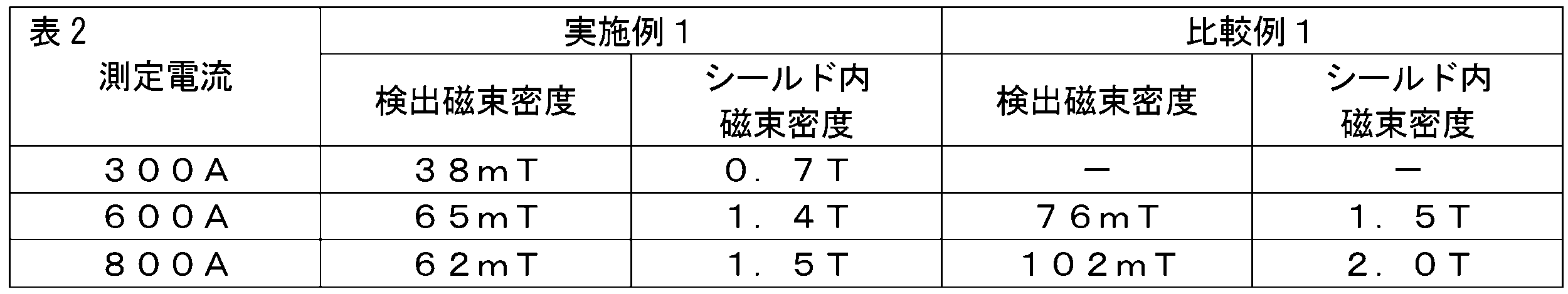
図5Aに示す電流センサ50について、隣接するユニット11のバスバ12に流れる電流によって生じる測定誤差を測定した。大電流用ユニット群51および小電流用ユニット群52として、以下の構成を備えたものを用いた。
[大電流用ユニット群51]
電流:800A
距離L1:2.6mm、距離L2:3.5mm(図1B参照)
間隔a1:12.5mm(図3参照)
[小電流用ユニット群52]
電流:300A
距離L1:2.6mm、距離L2:1.2mm(図1B参照)
間隔a2:13.5mm
隣接する大電流用ユニット11A1と小電流用ユニット11B3との間隔b:17.5mm
直線Cと直線DとのX軸方向における距離7.5mm(図5A参照)
図10に示す電流センサ80について、隣接するユニット11のバスバ12に流れる電流によって生じる測定誤差を測定した。電流センサ80は、大電流用ユニット群51に代えて、大電流用ユニット群81を備えている点において、実施例2の電流センサ50と異なっている。
大電流用ユニット群81と、大電流用ユニット群51とは、大電流用ユニット11Aの配置のみが異なっている。具体的には、図10に示すように、両側の大電流用ユニット11A1および11A3が直線D上に配置されており、大電流用ユニット11A1と11A3との間の大電流用ユニット11A2が直線C上に配置されている。
11、21:ユニット
11A、11A1、11A2、11A3、21A:大電流用ユニット
11B、11B1、11B2、11B3、21B:小電流用ユニット
11C :中電流用ユニット
12 :バスバ
12a :板面(一方の板面)
12b :板面(他方の板面)
13 :磁気センサ
14、24:シールド
14a、24a:基部
14b :立設部
14c :端
14e、24e:端部
31、51、81:大電流用ユニット群
32、52:小電流用ユニット群
53 :中電流用ユニット群
A、B:平面
C、D:直線
L1、L1A、L1B:距離(第1の距離)
L2、L2A、L2B:距離(第2の距離)
L3、L3A、L3B:距離(第3の距離)
a1、a2、b :間隔
Claims (10)
- 電流が流れる平板状でかつ第1方向へ延設されたバスバと、前記バスバの一方の板面に対向して配置された磁気センサと、前記バスバの他方の板面に対向して配置された平板状の基部を備えたシールドとを有するユニットを複数備え、複数の前記ユニットが一体に形成された電流センサであって、
複数の前記ユニットは、前記バスバに相対的に大きな電流が流れる大電流用ユニットと、前記バスバに相対的に小さな電流が流れる小電流用ユニットとを有しており、
前記バスバの前記板面の法線方向を第2方向、前記第1方向および前記第2方向に直交する方向を第3方向としたときに、
前記第2方向における、前記バスバと前記磁気センサとの間の第1の距離は、前記大電流用ユニットと前記小電流用ユニットとで同じであり、
前記第2方向における、前記バスバと前記基部との間の第2の距離は、前記大電流用ユニットが前記小電流用ユニットよりも大きいことを特徴とする、電流センサ。 - 前記大電流用ユニットと前記小電流用ユニットとは、前記バスバ、前記磁気センサおよび前記シールドが同じである、
請求項1に記載の電流センサ。 - 前記シールドは、前記基部の前記第3方向における両端に、前記第2方向における前記バスバおよび前記磁気センサが配置されている側へ延設された立設部をそれぞれ有する、請求項1に記載の電流センサ。
- 前記シールドの端部が、前記第2方向における、前記磁気センサと前記バスバとの間に位置する、
請求項3に記載の電流センサ。 - 複数の前記大電流用ユニットが前記第3方向に間隔a1で配置された大電流用ユニット群と、複数の前記小電流用ユニットが前記第3方向に間隔a2で配置された小電流用ユニット群と、を有しており、
隣り合う前記大電流用ユニットと前記小電流用ユニットとの間隔が間隔bであり、
前記大電流用ユニット群は前記大電流用ユニットの前記バスバが平面A上に配置され、
前記小電流用ユニット群は前記小電流用ユニットの前記バスバが平面B上に配置され、
前記平面Aと前記平面Bとは同一平面であり、
前記間隔bが前記間隔a1より大きく、
前記間隔bが前記間隔a2より大きい、
請求項1に記載の電流センサ。 - 複数の前記大電流用ユニットが前記第3方向に間隔a1で配置された大電流用ユニット群と、複数の前記小電流用ユニットが前記第3方向に間隔a2で配置された小電流用ユニット群と、を有しており、
隣り合う前記大電流用ユニットと前記小電流用ユニットとの間隔が間隔bであり、
前記大電流用ユニット群は前記大電流用ユニットの前記バスバが平面A上に配置され、
前記小電流用ユニット群は前記小電流用ユニットの前記バスバが平面B上に配置され、
前記平面Aと前記平面Bとは異なる平面であり、
前記間隔bが前記間隔a1以上であり、
前記間隔bが前記間隔a2以上である、
請求項1に記載の電流センサ。 - 複数の前記ユニットが前記第3方向に並べて配置され、
隣り合う前記ユニットの前記バスバに流れる電流の大きさが異なる場合、隣り合う前記ユニットは前記第3方向に延びる同一の直線上に配置されており、
隣り合う前記ユニットの前記バスバに流れる電流の大きさが同じ場合、隣り合う前記ユニットは前記第3方向に延びる同一の直線上に配置されていない、
請求項1ないし請求項3のいずれか1項に記載の電流センサ。 - 複数の前記大電流用ユニットを有する大電流用ユニット群と、複数の前記小電流用ユニットを有する小電流用ユニット群と、を有しており、
前記大電流用ユニット群は前記大電流用ユニットの前記バスバが平面A上に配置され、
前記小電流用ユニット群は前記小電流用ユニットの前記バスバが平面B上に配置され、
前記平面Aと前記平面Bとは同一平面であり、
前記大電流用ユニット群において、隣り合う前記大電流用ユニットは前記第3方向に延びる同一の直線上に配置されておらず、
前記小電流用ユニット群において、隣り合う前記小電流用ユニットは前記第3方向に延びる同一の直線上に配置されておらず、
隣接する前記大電流用ユニットと前記小電流用ユニットとは、前記第3方向に延びる同一の直線上に配置されている、
請求項1ないし請求項3のいずれか1項に記載の電流センサ。 - 複数の前記小電流用ユニットを有する小電流用ユニット群と、前記大電流用ユニットと、を有しており、
前記大電流用ユニットの前記バスバが平面A上に配置され、
前記小電流用ユニット群は前記小電流用ユニットの前記バスバが平面B上に配置され、
前記平面Aと前記平面Bとは同一平面であり、
前記小電流用ユニット群における、隣り合う前記小電流用ユニットは前記第3方向に延びる同一の直線上に配置されておらず、
隣接する前記大電流用ユニットと前記小電流用ユニットとは、前記第3方向に延びる同一の直線上に配置されている、
請求項1ないし請求項3のいずれか1項に記載の電流センサ。 - 前記大電流用ユニットに流れる電流の電流値と、前記小電流用ユニットに流れる電流の電流値との間の大きさの電流値の電流が流れる中電流用ユニットをさらに備えている、
請求項1に記載の電流センサ。
Priority Applications (3)
| Application Number | Priority Date | Filing Date | Title |
|---|---|---|---|
| JP2023578400A JP7579466B2 (ja) | 2022-02-04 | 2022-12-09 | 電流センサ |
| EP22924986.7A EP4474833A4 (en) | 2022-02-04 | 2022-12-09 | ELECTRICAL CURRENT SENSOR |
| US18/767,125 US20240361362A1 (en) | 2022-02-04 | 2024-07-09 | Current sensor |
Applications Claiming Priority (2)
| Application Number | Priority Date | Filing Date | Title |
|---|---|---|---|
| JP2022-016502 | 2022-02-04 | ||
| JP2022016502 | 2022-02-04 |
Related Child Applications (1)
| Application Number | Title | Priority Date | Filing Date |
|---|---|---|---|
| US18/767,125 Continuation US20240361362A1 (en) | 2022-02-04 | 2024-07-09 | Current sensor |
Publications (1)
| Publication Number | Publication Date |
|---|---|
| WO2023149082A1 true WO2023149082A1 (ja) | 2023-08-10 |
Family
ID=87552067
Family Applications (1)
| Application Number | Title | Priority Date | Filing Date |
|---|---|---|---|
| PCT/JP2022/045525 Ceased WO2023149082A1 (ja) | 2022-02-04 | 2022-12-09 | 電流センサ |
Country Status (4)
| Country | Link |
|---|---|
| US (1) | US20240361362A1 (ja) |
| EP (1) | EP4474833A4 (ja) |
| JP (1) | JP7579466B2 (ja) |
| WO (1) | WO2023149082A1 (ja) |
Citations (6)
| Publication number | Priority date | Publication date | Assignee | Title |
|---|---|---|---|---|
| JPH0875817A (ja) * | 1994-08-31 | 1996-03-22 | Advantest Corp | 電圧印加電流測定装置 |
| JP2016001168A (ja) | 2014-05-23 | 2016-01-07 | 株式会社デンソー | 電流センサ付バスバーモジュール |
| JP2016148620A (ja) * | 2015-02-13 | 2016-08-18 | 株式会社フジクラ | 電流センサ |
| WO2018150802A1 (ja) * | 2017-02-17 | 2018-08-23 | アルプス電気株式会社 | 電流センサ |
| JP2020115104A (ja) * | 2019-01-18 | 2020-07-30 | 株式会社デンソー | 電流センサ |
| WO2021070834A1 (ja) * | 2019-10-08 | 2021-04-15 | アルプスアルパイン株式会社 | 電流検出装置 |
Family Cites Families (3)
| Publication number | Priority date | Publication date | Assignee | Title |
|---|---|---|---|---|
| JP2013113630A (ja) * | 2011-11-25 | 2013-06-10 | Yazaki Corp | 電流検出装置 |
| JP6890112B2 (ja) * | 2018-11-15 | 2021-06-18 | 矢崎総業株式会社 | 電流検出装置 |
| JP7466646B2 (ja) * | 2020-07-14 | 2024-04-12 | アルプスアルパイン株式会社 | 電流検出装置 |
-
2022
- 2022-12-09 JP JP2023578400A patent/JP7579466B2/ja active Active
- 2022-12-09 EP EP22924986.7A patent/EP4474833A4/en active Pending
- 2022-12-09 WO PCT/JP2022/045525 patent/WO2023149082A1/ja not_active Ceased
-
2024
- 2024-07-09 US US18/767,125 patent/US20240361362A1/en active Pending
Patent Citations (6)
| Publication number | Priority date | Publication date | Assignee | Title |
|---|---|---|---|---|
| JPH0875817A (ja) * | 1994-08-31 | 1996-03-22 | Advantest Corp | 電圧印加電流測定装置 |
| JP2016001168A (ja) | 2014-05-23 | 2016-01-07 | 株式会社デンソー | 電流センサ付バスバーモジュール |
| JP2016148620A (ja) * | 2015-02-13 | 2016-08-18 | 株式会社フジクラ | 電流センサ |
| WO2018150802A1 (ja) * | 2017-02-17 | 2018-08-23 | アルプス電気株式会社 | 電流センサ |
| JP2020115104A (ja) * | 2019-01-18 | 2020-07-30 | 株式会社デンソー | 電流センサ |
| WO2021070834A1 (ja) * | 2019-10-08 | 2021-04-15 | アルプスアルパイン株式会社 | 電流検出装置 |
Non-Patent Citations (1)
| Title |
|---|
| See also references of EP4474833A4 |
Also Published As
| Publication number | Publication date |
|---|---|
| EP4474833A4 (en) | 2026-01-14 |
| US20240361362A1 (en) | 2024-10-31 |
| JP7579466B2 (ja) | 2024-11-07 |
| JPWO2023149082A1 (ja) | 2023-08-10 |
| EP4474833A1 (en) | 2024-12-11 |
Similar Documents
| Publication | Publication Date | Title |
|---|---|---|
| JP5732679B2 (ja) | 電流センサ | |
| US8878520B2 (en) | Current sensor | |
| US9069016B2 (en) | Current sensor | |
| US10060953B2 (en) | Current sensor | |
| JP7003609B2 (ja) | 電流センサ | |
| JP5659389B2 (ja) | 電流センサ | |
| US20130169267A1 (en) | Current sensor | |
| JP7047435B2 (ja) | 電流センサの設計方法 | |
| JP2018004314A (ja) | 電流センサ | |
| US20140232376A1 (en) | Current sensor | |
| US9335349B2 (en) | Current sensor | |
| US10794935B2 (en) | Current sensor | |
| JP2007183221A (ja) | 電流センサ | |
| WO2022065311A1 (ja) | 電流検出装置 | |
| US11209466B2 (en) | Current sensor | |
| WO2013038867A1 (ja) | 電流センサ | |
| JP6671986B2 (ja) | 電流センサおよびその製造方法 | |
| WO2023149082A1 (ja) | 電流センサ | |
| JP7003608B2 (ja) | 電流センサ | |
| JP3191252U (ja) | 電流センサ | |
| JP2019007935A (ja) | 電流センサ | |
| US20200018804A1 (en) | Electric current sensor | |
| JP6031639B2 (ja) | 電流センサ | |
| WO2025263082A1 (ja) | 電流センサ | |
| WO2024095585A1 (ja) | 電流センサ |
Legal Events
| Date | Code | Title | Description |
|---|---|---|---|
| 121 | Ep: the epo has been informed by wipo that ep was designated in this application |
Ref document number: 22924986 Country of ref document: EP Kind code of ref document: A1 |
|
| WWE | Wipo information: entry into national phase |
Ref document number: 2023578400 Country of ref document: JP |
|
| WWE | Wipo information: entry into national phase |
Ref document number: 2022924986 Country of ref document: EP |
|
| NENP | Non-entry into the national phase |
Ref country code: DE |
|
| ENP | Entry into the national phase |
Ref document number: 2022924986 Country of ref document: EP Effective date: 20240904 |