WO2023149099A1 - スクロール圧縮機 - Google Patents
スクロール圧縮機 Download PDFInfo
- Publication number
- WO2023149099A1 WO2023149099A1 PCT/JP2022/046082 JP2022046082W WO2023149099A1 WO 2023149099 A1 WO2023149099 A1 WO 2023149099A1 JP 2022046082 W JP2022046082 W JP 2022046082W WO 2023149099 A1 WO2023149099 A1 WO 2023149099A1
- Authority
- WO
- WIPO (PCT)
- Prior art keywords
- space
- bearing
- thrust plate
- scroll
- bearing support
- Prior art date
- Legal status (The legal status is an assumption and is not a legal conclusion. Google has not performed a legal analysis and makes no representation as to the accuracy of the status listed.)
- Ceased
Links
Images

Classifications
-
- F—MECHANICAL ENGINEERING; LIGHTING; HEATING; WEAPONS; BLASTING
- F04—POSITIVE - DISPLACEMENT MACHINES FOR LIQUIDS; PUMPS FOR LIQUIDS OR ELASTIC FLUIDS
- F04C—ROTARY-PISTON, OR OSCILLATING-PISTON, POSITIVE-DISPLACEMENT MACHINES FOR LIQUIDS; ROTARY-PISTON, OR OSCILLATING-PISTON, POSITIVE-DISPLACEMENT PUMPS
- F04C29/00—Component parts, details or accessories of pumps or pumping installations, not provided for in groups F04C18/00 - F04C28/00
- F04C29/02—Lubrication; Lubricant separation
-
- F—MECHANICAL ENGINEERING; LIGHTING; HEATING; WEAPONS; BLASTING
- F04—POSITIVE - DISPLACEMENT MACHINES FOR LIQUIDS; PUMPS FOR LIQUIDS OR ELASTIC FLUIDS
- F04C—ROTARY-PISTON, OR OSCILLATING-PISTON, POSITIVE-DISPLACEMENT MACHINES FOR LIQUIDS; ROTARY-PISTON, OR OSCILLATING-PISTON, POSITIVE-DISPLACEMENT PUMPS
- F04C18/00—Rotary-piston pumps specially adapted for elastic fluids
- F04C18/02—Rotary-piston pumps specially adapted for elastic fluids of arcuate-engagement type, i.e. with circular translatory movement of co-operating members, each member having the same number of teeth or tooth-equivalents
- F04C18/0207—Rotary-piston pumps specially adapted for elastic fluids of arcuate-engagement type, i.e. with circular translatory movement of co-operating members, each member having the same number of teeth or tooth-equivalents both members having co-operating elements in spiral form
- F04C18/0215—Rotary-piston pumps specially adapted for elastic fluids of arcuate-engagement type, i.e. with circular translatory movement of co-operating members, each member having the same number of teeth or tooth-equivalents both members having co-operating elements in spiral form where only one member is moving
-
- F—MECHANICAL ENGINEERING; LIGHTING; HEATING; WEAPONS; BLASTING
- F04—POSITIVE - DISPLACEMENT MACHINES FOR LIQUIDS; PUMPS FOR LIQUIDS OR ELASTIC FLUIDS
- F04C—ROTARY-PISTON, OR OSCILLATING-PISTON, POSITIVE-DISPLACEMENT MACHINES FOR LIQUIDS; ROTARY-PISTON, OR OSCILLATING-PISTON, POSITIVE-DISPLACEMENT PUMPS
- F04C27/00—Sealing arrangements in rotary-piston pumps specially adapted for elastic fluids
- F04C27/005—Axial sealings for working fluid
-
- F—MECHANICAL ENGINEERING; LIGHTING; HEATING; WEAPONS; BLASTING
- F04—POSITIVE - DISPLACEMENT MACHINES FOR LIQUIDS; PUMPS FOR LIQUIDS OR ELASTIC FLUIDS
- F04C—ROTARY-PISTON, OR OSCILLATING-PISTON, POSITIVE-DISPLACEMENT MACHINES FOR LIQUIDS; ROTARY-PISTON, OR OSCILLATING-PISTON, POSITIVE-DISPLACEMENT PUMPS
- F04C29/00—Component parts, details or accessories of pumps or pumping installations, not provided for in groups F04C18/00 - F04C28/00
- F04C29/02—Lubrication; Lubricant separation
- F04C29/021—Control systems for the circulation of the lubricant
-
- F—MECHANICAL ENGINEERING; LIGHTING; HEATING; WEAPONS; BLASTING
- F04—POSITIVE - DISPLACEMENT MACHINES FOR LIQUIDS; PUMPS FOR LIQUIDS OR ELASTIC FLUIDS
- F04C—ROTARY-PISTON, OR OSCILLATING-PISTON, POSITIVE-DISPLACEMENT MACHINES FOR LIQUIDS; ROTARY-PISTON, OR OSCILLATING-PISTON, POSITIVE-DISPLACEMENT PUMPS
- F04C29/00—Component parts, details or accessories of pumps or pumping installations, not provided for in groups F04C18/00 - F04C28/00
- F04C29/02—Lubrication; Lubricant separation
- F04C29/028—Means for improving or restricting lubricant flow
-
- F—MECHANICAL ENGINEERING; LIGHTING; HEATING; WEAPONS; BLASTING
- F04—POSITIVE - DISPLACEMENT MACHINES FOR LIQUIDS; PUMPS FOR LIQUIDS OR ELASTIC FLUIDS
- F04C—ROTARY-PISTON, OR OSCILLATING-PISTON, POSITIVE-DISPLACEMENT MACHINES FOR LIQUIDS; ROTARY-PISTON, OR OSCILLATING-PISTON, POSITIVE-DISPLACEMENT PUMPS
- F04C29/00—Component parts, details or accessories of pumps or pumping installations, not provided for in groups F04C18/00 - F04C28/00
- F04C29/04—Heating; Cooling; Heat insulation
- F04C29/045—Heating; Cooling; Heat insulation of the electric motor in hermetic pumps
-
- F—MECHANICAL ENGINEERING; LIGHTING; HEATING; WEAPONS; BLASTING
- F04—POSITIVE - DISPLACEMENT MACHINES FOR LIQUIDS; PUMPS FOR LIQUIDS OR ELASTIC FLUIDS
- F04C—ROTARY-PISTON, OR OSCILLATING-PISTON, POSITIVE-DISPLACEMENT MACHINES FOR LIQUIDS; ROTARY-PISTON, OR OSCILLATING-PISTON, POSITIVE-DISPLACEMENT PUMPS
- F04C29/00—Component parts, details or accessories of pumps or pumping installations, not provided for in groups F04C18/00 - F04C28/00
- F04C29/12—Arrangements for admission or discharge of the working fluid, e.g. constructional features of the inlet or outlet
-
- F—MECHANICAL ENGINEERING; LIGHTING; HEATING; WEAPONS; BLASTING
- F04—POSITIVE - DISPLACEMENT MACHINES FOR LIQUIDS; PUMPS FOR LIQUIDS OR ELASTIC FLUIDS
- F04C—ROTARY-PISTON, OR OSCILLATING-PISTON, POSITIVE-DISPLACEMENT MACHINES FOR LIQUIDS; ROTARY-PISTON, OR OSCILLATING-PISTON, POSITIVE-DISPLACEMENT PUMPS
- F04C23/00—Combinations of two or more pumps, each being of rotary-piston or oscillating-piston type, specially adapted for elastic fluids; Pumping installations specially adapted for elastic fluids; Multi-stage pumps specially adapted for elastic fluids
- F04C23/008—Hermetic pumps
Definitions
- the present disclosure relates to scroll compressors.
- Patent Document 1 a scroll compressor having a fixed scroll and an orbiting scroll that meshes with the fixed scroll is known (see Patent Document 1, for example).
- the compressor-side housing and the electric-motor-side housing are separated from each other by fixing the compressor-side housing and the electric-motor-side housing with a partition member interposed therebetween.
- the partition member is provided with a plurality of air inlets for communicating the rooms on both sides.
- the refrigerant gas After cooling the electric motor while circulating through the electric motor side housing, the refrigerant gas flows into the compressor side housing through the intake port of the partition member. Refrigerant gas that has flowed into the compressor-side housing is sucked into the variable volume chamber between the fixed scroll and the orbiting scroll, is compressed, becomes high pressure, and is discharged from the end of the compressor-side housing.
- the refrigerant gas contains oil, and the oil becomes a mist and floats in the housing, lubricating each part in the housing.
- Patent Document 1 refrigerant gas led to a plurality of intake ports formed in a partition member is supplied to a main bearing that supports a main shaft that is connected to the rotating shaft of a motor and a drive that is attached to the back surface of an orbiting scroll. It is sucked into the variable volume chamber between the fixed scroll and the orbiting scroll without passing through the area where bearings and the like are arranged. Therefore, the oil contained in the refrigerant gas cannot be efficiently supplied to lubricate the main bearings and drive bearings.
- An object of the present invention is to provide an efficient scroll compressor.
- a scroll compressor includes: a compression section including a fixed scroll and an orbiting scroll meshed with the fixed scroll; a motor for orbiting the orbiting scroll with respect to the fixed scroll; A rotary shaft that rotates about an axis and is attached to the orbiting scroll through an eccentric shaft arranged eccentrically from the axis; a bearing that supports the rotary shaft; and a housing having an internal space for accommodating the motor and the compression section, the housing defining the internal space as a first space in which the motor is arranged and a second space in which the bearing section and the compression section are arranged.
- the partition wall is a first series that guides a mixed refrigerant containing lubricating oil and refrigerant gas from the first space to a region of the second space where the bearing is arranged. and a second communication passage for guiding the refrigerant gas contained in the mixed refrigerant guided to the region of the second space to the compression portion.
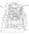
- FIG. 1 is a vertical cross-sectional view showing a schematic configuration of a scroll compressor according to an embodiment of the present disclosure
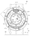
- FIG. 2 is a plan view of the thrust plate shown in FIG. 1
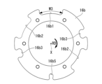
- FIG. 3 is a view showing a state where a thrust plate is attached to the housing shown in FIG. 2
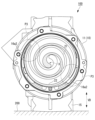
- It is a figure which shows the state which attached the compression part to the housing shown in FIG.
- It is the figure which looked at the housing of the scroll compressor of the modification from the compression part side.
- FIG. 1 is a longitudinal sectional view showing a schematic configuration of a scroll compressor according to this embodiment.
- the scroll compressor 100 of this embodiment is used, for example, in a vehicle air conditioner.
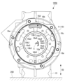
- FIG. 2 is a view of the housing of the scroll compressor shown in FIG. 1 as viewed from the compression section side.
- FIG. 1 is a cross-sectional view of the scroll compressor 100 shown in FIG. 2 taken along line AA.
- a rotation direction RD indicates the rotation direction of the rotating shaft 40 .
- the scroll compressor 100 includes a housing 10, a compression section 20, a motor 30, a rotating shaft 40, a bearing section 50, a bearing section 60, a balance weight 70, an inverter 80, have
- the housing 10 forms the outer shell of the scroll compressor 100 and is made of an aluminum alloy.
- the housing 10 has a first housing 11 , a second housing 12 and a third housing 13 .
- the first housing 11, the second housing 12, and the third housing 13 are configured to be integrated by fastening with bolts 14.
- the housing 10 is fixed to the housing 200 via the legs 15 with the axis X arranged in the horizontal direction.
- the housing 10 is provided with an intake port P1 on the upper side in the vertical direction (gravitational direction) VD.
- Refrigerant supplied from the outside is introduced into the internal space IS of the housing 10 from the intake port P1.
- Refrigerant introduced into housing 10 is guided along axis X through motor 30 toward compression section 20 .
- the refrigerant sucked from the intake port P1 is a mixed refrigerant containing lubricating oil and refrigerant gas.
- the first housing 11 is formed in a substantially cylindrical shape along the axis X and has an internal space IS that accommodates the compression section 20 and the motor 30 .
- the second housing 12 seals one end of the first housing 11 along the axis X, and is provided with a discharge port (not shown) for the refrigerant gas compressed by the compression section 20 .
- the third housing 13 seals the other end of the first housing 11 along the axis X, and has a space for accommodating the inverter 80 therein.
- the housing 10 has a partition wall portion 16 that divides the internal space IS into a first space IS1 in which the motor 30 is arranged and a second space IS2 in which the bearing portion 50 and the compression portion 20 are arranged.
- the partition wall portion 16 has a bearing support portion 16a integrally formed with the first housing 11 and a thrust plate 16b. The details of the partition 16 will be described later.
- the compression part 20 is a device that is arranged inside the first housing 11 and rotates around the axis X to compress the refrigerant gas.
- the compression section 20 has a fixed scroll 21 fixed to the second housing 12 and an orbiting scroll 22 meshed with the fixed scroll 21 .
- the compression unit 20 compresses the refrigerant gas by orbiting the orbiting scroll 22 with respect to the fixed scroll 21 with the driving force of the motor 30 .
- the motor 30 is a device that causes the orbiting scroll 22 of the compression section 20 to revolve around the axis X with respect to the fixed scroll 21 .
- the motor 30 has a stator 31 and a rotor 32 .
- the rotor 32 is connected to the rotating shaft 40 .
- the rotating shaft 40 is a shaft-like member that rotates around the axis X by the motor 30 .
- One end of the rotating shaft 40 is supported by a bearing portion 60 fixed to the third housing 13 .
- the other end of the rotating shaft 40 is supported by a bearing portion 50 fixed to the bearing support portion 16a.
- An eccentric shaft 41 arranged eccentrically with respect to the axis X is provided at the end portion of the rotating shaft 40 on the side of the compression section 20 .
- the eccentric shaft 41 is rotatably attached to a bearing portion 22b fixed to the back surface of the orbiting scroll 22 via a balance weight 70.
- the rotary shaft 40 is thus attached to the orbiting scroll 22 via the eccentric shaft 41 .
- the bearing portion 50 is a member that is press-fitted into the bearing support portion 16a and supports the rotary shaft 40 so as to be rotatable around the axis X.
- the bearing portion 60 is a member that is press-fitted into the third housing 13 and supports the rotating shaft 40 rotatably around the axis X. As shown in FIG.
- the balance weight 70 is a member fixed to the eccentric shaft 41 of the rotating shaft 40 and rotating around the axis X.
- the balance weight 70 cancels out vibration caused by the revolution orbiting motion of the orbiting scroll 22 .
- the inverter 80 is a device that generates a drive voltage for driving the motor 30 and controls the rotation speed of the motor 30 .
- the bearing support portion 16a is a member that partitions the internal space IS into a first space IS1 and a second space IS2 and into which the bearing portion 50 is press-fitted. As shown in FIG. 2, two through holes 16a1, two through holes 16a2, and two through holes 16a3 are formed in the thrust plate 16b side surface of the bearing support portion 16a.
- the through holes 16a1, 16a2, and 16a3 are holes that allow the surface of the bearing support portion 16a on the motor 30 side and the surface on the compression portion 20 side to communicate with each other.
- a through hole 16a1 and a groove 16a4 communicating with the second space IS2 are formed on the thrust plate 16b side surface of the bearing support 16a.
- the grooves 16a4 are formed at two locations so as to extend in a radial direction perpendicular to the axis X.
- the groove portion 16a4 radially guides the mixed refrigerant guided from the through hole 16a1 to the region of the second space IS2 where the bearing portion 50 is arranged.
- the groove portion 16a4 is hatched.
- the groove portion 16a5 is hatched.
- a groove portion 16a5 communicating with the second space IS2 is formed on the thrust plate 16b side surface of the bearing support portion 16a.
- One groove portion 16a5 is formed at the upper end of the bearing support portion 16a in the vertical direction VD so as to extend in a radial direction perpendicular to the axis X.
- the width of the inlet region (inner peripheral side region) of the groove portion 16a5 in the rotational direction RD (the circumferential direction around the axis X) is W1.
- the width of the outlet region (outer peripheral region) of the groove portion 16a5 in the rotation direction RD is W2, which is wider than W1.
- the thrust plate 16b is a plate-shaped member that is attached to the bearing support portion 16a and that supports the orbiting scroll 22 with a sliding surface 16bA that contacts the end surface 22a of the orbiting scroll 22 of the compression portion 20.
- FIG. 3 is a plan view of the thrust plate 16b shown in FIG. 1.
- the thrust plate 16b is formed with a notch portion 16b1 arranged at a position corresponding to the groove portion 16a5 formed in the bearing support portion 16a.
- the cutout portion 16b1 has a shape that blocks the entrance region of the groove portion 16a5 and avoids blocking the exit region of the groove portion 16a5.
- the width of the notch 16b1 in the rotation direction RD is W3.
- the width W1 of the inlet region of the groove portion 16a5 of the bearing support portion 16a is narrower than the width W3 of the notch portion 16b1.
- the width W3 of the notch portion 16b1 substantially matches the width W2 of the outlet region of the groove portion 16a5 of the bearing support portion 16a.
- the thrust plate 16b is formed with a notch portion 16b2 arranged at a position corresponding to the through hole 16a2 formed in the bearing support portion 16a.
- the notch 16b2 has a shape that avoids blocking the area overlapping the through hole 16a2.
- the width of the notch portion 16b2 substantially matches the width of the through hole 16a2 of the bearing support portion 16a.
- the thrust plate 16b is formed with a notch portion 16b3 arranged at a position corresponding to the through hole 16a3 formed in the bearing support portion 16a.
- the notch 16b3 has a shape that avoids blocking the area overlapping the through hole 16a3.
- the width of the notch portion 16b3 substantially matches the width of the through hole 16a3 of the bearing support portion 16a.
- FIG. 4 is a diagram showing a state where the thrust plate 16b is attached to the housing 10 shown in FIG. As shown in FIG. 4, the through hole 16a1, the grooves 16a4, and the grooves 16a5 formed in the bearing support portion 16a are covered with the facing surface 16bB (see FIG. 1) of the thrust plate 16b.
- the facing surface 16bB is a surface facing the thrust plate 16b side surface of the bearing support portion 16a.
- the mixed refrigerant guided from the first space IS1 to the through hole 16a1 collides with the facing surface 16bB of the thrust plate 16b and is guided to the groove 16a4 communicating with the through hole 16a1.
- the mixed refrigerant guided to the groove portion 16a4 is guided toward the axis X along the radial direction perpendicular to the axis X. As shown in FIG.
- the region where the mixed refrigerant is guided is the region where the bearing portion 50 of the second space IS2 is arranged.
- the partition wall portion 16 configured by the bearing support portion 16a and the thrust plate 16b moves the mixed refrigerant containing the lubricating oil and the refrigerant gas from the first space IS1 to the area where the bearing portion 50 is arranged in the second space IS2.
- the first communication path 16c is formed by the through hole 16a1, the groove portion 16a4, and the facing surface 16bB of the thrust plate 16b.
- the mixed refrigerant guided to the region of the second space IS2 where the bearing portion 50 is arranged flows along the rotation direction RD, flows into the inlet region of the groove portion 16a5 of the bearing support portion 16a, and is guided to the outlet region.
- the refrigerant gas guided to the outlet region of the groove portion 16a5 is guided to the region of the second space IS2 where the compression portion 20 is arranged via the notch portion 16b1.
- the partition wall portion 16 forms the second communication passage 16d (see FIG. 1) that guides the refrigerant gas contained in the mixed refrigerant guided to the region where the bearing portion 50 is arranged in the second space IS2 to the compression portion 20. have.
- the second communication path 16d is formed by the groove portion 16a5, the facing surface 16bB of the thrust plate 16b, and the notch portion 16b1.
- the mixed refrigerant guided from the first space IS1 to the through hole 16a2 is guided from the first space IS1 to the suction position P3 of the compression part 20 in the second space IS2 without passing through the area where the bearing part 50 is arranged. This is because the notch 16b2 is formed at a position corresponding to the through hole 16a2 of the thrust plate 16b.
- the intake position P3 is the end portion (end of winding) of the fixed scroll 21 .
- the intake position P3 is the end of the orbiting scroll 22 (end of winding).
- the partition wall 16 has the third communication passage 16e that guides the refrigerant gas from the first space IS1 to the compression portion 20 in the second space IS2 without passing through the area where the bearing portion 50 is arranged.
- the third communication passage 16e guides the refrigerant gas to the suction position P3 where the end of the fixed scroll 21 or the end of the orbiting scroll 22 is arranged.
- the mixed refrigerant guided from the first space IS1 to the through hole 16a3 is guided from the first space IS1 to the compression part 20 of the second space IS2 without passing through the area where the bearing part 50 is arranged. This is because the notch 16b3 is formed at a position corresponding to the through hole 16a3 of the thrust plate 16b.
- the thrust plate 16b is formed with a notch (oil return portion) 16b5 for returning lubricating oil (not shown) remaining below the housing 10 in the vertical direction VD from the sliding surface 16bA side to the opposing surface 16bB side.
- the second communication path 16d is formed on the opposite side of the axis X from the notch 16b5.
- the second communication path 16d is formed at a position apart from the notch 16b5 in the circumferential direction around the axis X within an angular range of 90 degrees or more and 270 degrees or less.
- the first communication path 16c is arranged at two positions, one at a position about 135 degrees away from the position at which the second communication path 16d is arranged and the other at a position about 315 degrees away from the position opposite to the rotational direction RD. shall be.
- the position where the first communication path 16c is arranged and the position where the second communication path 16d is arranged are separated by about 135 degrees or more in the rotation direction RD.
- FIG. 4 may be changed to other modifications.
- the position where the first communication path 16c is arranged and the position where the second communication path 16d is arranged may be separated by 180 degrees or more in the rotation direction RD.
- FIG. 6 is a view of the housing 10 of the modified scroll compressor 100A viewed from the compression section 20 side.
- the first communication path 16c is arranged only at one position, which is about 315 degrees away from the position where the second communication path 16d is arranged in the direction opposite to the rotational direction RD.
- the position where the first communication path 16c is arranged and the position where the second communication path 16d is arranged are separated by about 315 degrees in the rotation direction RD.
- the area where the bearing portion 50 of the second space IS2 is arranged from the first communication path 16c increases as the position where the first communication path 16c is arranged and the position where the second communication path 16d is arranged are separated in the rotation direction RD.
- the lubricating oil contained in the mixed refrigerant guided to the second communication passage 16d is suppressed from being guided to the second communication passage 16d. This is because the longer the rotation direction RD from the first communication passage 16c to the second communication passage 16d, the easier it is for the lubricating oil to separate from the refrigerant gas.
- the first communication path 16c is arranged only at one position which is about 315 degrees away from the position where the second communication path 16d is arranged in the direction opposite to the rotational direction RD. is possible.
- other positions may be used as long as the position where the first communication path 16c is arranged and the position where the second communication path 16d are arranged are separated by 180 degrees or more in the rotational direction RD.
- the rotating shaft 40 is rotated around the axis X by the motor 30, and the orbiting scroll 22 to which the rotating shaft 40 is attached via the eccentric shaft 41 revolves around the fixed scroll 21. It rotates to compress and discharge the refrigerant gas.
- the internal space IS of the housing 10 accommodating the motor 30 and the compression section 20 is divided into a first space IS1 in which the motor 30 is arranged and a second space IS2 in which the bearing section 50 and the compression section 20 are arranged. partitioned.
- a mixed refrigerant containing lubricating oil and refrigerant gas is guided from the first space IS1 to the area of the second space IS2 where the bearing portion 50 is arranged by the first communication passage 16c of the partition wall portion 16.
- Refrigerant gas contained in the mixed refrigerant guided to the region where the bearing portion 50 of the second space IS2 is arranged is guided to the compression portion 20 by the second communication passage 16d.
- the mixed refrigerant supplied from the suction port P1 to the first space IS1 is guided to the groove portion 16a4 through the through hole 16a1, and the opposing surface 16bB between the groove portion 16a4 and the thrust plate 16b is introduced. and can be guided to the area where the bearing portion 50 of the second space IS2 is arranged.
- the refrigerant gas contained in the mixed refrigerant supplied to the second space IS2 is allowed to pass through between the groove portion 16a5 and the facing surface 16bB of the thrust plate 16b, and is discharged from the notch portion 16b1. It can be led to the compression section 20 .
- the third communication passage 16e allows the flow from the first space IS1 to the suction position P3 of the compression portion 20 in the second space IS2 without passing through the region where the bearing portion 50 is arranged.
- a refrigerant gas is introduced. Therefore, the refrigerant gas can be directly guided to the suction position P3 of the compression section 20 without generating heat loss due to the refrigerant gas passing through the bearing portion 50 and being heated.
- the second communication passage 16d is formed on the opposite side of the axis X from the position where the notch portion 16b5 is formed. Therefore, it is possible to appropriately prevent the lubricating oil from being led to the second communication path 16d.
- the width W1 of the groove portion 16a5 is narrower than the width W3 of the notch portion 16b1. It is possible to suppress the lubricating oil contained from being led to the compression portion 20 from the notch portion 16b1.
- the position at which the first communication path 16c is arranged and the position at which the second communication path 16d are arranged are separated by 180 degrees or more.
- the lubricating oil that has flowed into the second space IS2 from the passage 16c can be moved in the rotational direction RD by 180 degrees or more. Therefore, compared to the case where the angle between the position where the first communication path 16c is arranged and the position where the second communication path 16d is arranged is less than 180 degrees, the lubricating oil that stays around the bearing portion 50 can be increased.
- a scroll compressor (100) includes a compression section (20) having a fixed scroll (21) and an orbiting scroll (22) meshing with the fixed scroll; a motor (30) for revolving, a rotary shaft (40) that rotates around an axis (X) by the motor and is attached to the orbiting scroll via an eccentric shaft (41) that is arranged eccentrically from the axis; a bearing (50) that supports the rotating shaft; and a housing (10) that is cylindrically formed along the axis and has an internal space (IS) that houses the motor and the compression unit,
- the housing has a partition (16) that divides the internal space (IS) into a first space (IS1) in which the motor is arranged and a second space (S2) in which the bearing and the compression section are arranged.
- the partition wall portion includes a first communication passage (16c) for guiding a mixed refrigerant containing lubricating oil and refrigerant gas from the first space to a region of the second space where the bearing portion is arranged; and a second communication passage (16d) for guiding the refrigerant gas contained in the mixed refrigerant guided to the region of the two spaces to the compression section.
- the rotating shaft is rotated around the axis by the motor, and the orbiting scroll to which the rotating shaft is attached via the eccentric shaft revolves around the fixed scroll to compress the refrigerant gas. to dispense.
- the internal space of the housing that accommodates the motor and the compression section is partitioned by the partition into a first space in which the motor is arranged and a second space in which the bearing section and the compression section are arranged.
- a mixed refrigerant containing lubricating oil and refrigerant gas is guided from the first space to a region of the second space where the bearing is arranged by the first communication passage of the partition.
- Refrigerant gas contained in the mixed refrigerant guided to the area where the bearing portion of the second space is arranged is guided to the compression portion by the second communication passage.
- the partition wall section includes a bearing support section (16a) that partitions the internal space into the first space and the second space and into which the bearing section is press-fitted, and the bearing support section. and a plate-like thrust plate (16b) that supports the orbiting scroll by means of a sliding surface that is attached to the orbiting scroll and contacts the end surface of the orbiting scroll, and the first communication passage (16c) is connected to the bearing support portion.
- the mixed refrigerant supplied to the first space is guided to the first groove portion through the through hole, passed between the first groove portion and the facing surface of the thrust plate, and It can lead to the area where the two-spatial bearing is arranged.
- the second communication passage (16d) includes a second groove portion (16a5) formed in the thrust plate side surface of the bearing support portion and A configuration may be adopted in which the facing surface of the disposed thrust plate on the side of the bearing support portion and a notch portion formed in the thrust plate and guiding the refrigerant gas from the second groove portion to the compression portion are formed.
- the refrigerant gas contained in the mixed refrigerant supplied to the second space is passed between the second groove portion and the facing surface of the thrust plate, and is guided from the notch portion to the compression portion. can be done.
- the partition wall section partitions the internal space into the first space and the second space and is attached to a bearing support section into which the bearing section is press-fitted, and the bearing support section. and a plate-shaped thrust plate that supports the orbiting scroll by a sliding surface that contacts the end surface of the orbiting scroll, and the second communication passage is formed on the surface of the bearing support portion on the thrust plate side.
- a second groove formed on the surface of the thrust plate disposed so as to cover the second groove; It may be configured to be formed by a notch for guiding the refrigerant gas.
- the refrigerant gas contained in the mixed refrigerant supplied to the second space is passed between the second groove portion and the facing surface of the thrust plate, and is guided from the notch portion to the compression portion. can be done.
- the partition wall section includes a third series that guides the refrigerant gas from the first space to the compression section in the second space without passing through the region where the bearing section is arranged.
- a passage (16e) may be provided, and the third communication passage may be configured to guide the refrigerant gas to a suction position (P3) where the end of the fixed scroll or the end of the orbiting scroll is arranged.
- the refrigerant gas is guided from the first space to the suction position of the compression portion in the second space by the third communication passage without passing through the area where the bearing portion is arranged. Therefore, the refrigerant gas can be directly guided to the suction position of the compression section without generating heat loss due to the refrigerant gas passing through the bearing and being heated.
- the thrust plate is provided with an oil return portion (16b5) for returning the lubricating oil remaining below the housing from the sliding surface side to the opposing surface side
- the second communication path may be formed on the side opposite to the position where the oil return portion is formed with respect to the axis.
- the second communication passage is formed on the side opposite to the position where the oil return portion is formed with respect to the axis. Therefore, it is possible to appropriately prevent the lubricating oil from being led to the second communication passage.
- the width of the second groove portion may be narrower than the width of the notch portion in the rotation direction of the rotating shaft. According to the scroll compressor of this configuration, since the width of the second groove portion is narrower than the width of the notch portion, compared to the case where the width of the second groove portion is the same as the width of the notch portion, the lubricating oil contained in the mixed refrigerant can be suppressed from being guided from the cutout portion to the compression portion.
- a position where the first communication path is arranged and a position where the second communication path is arranged may be separated by 180 degrees or more in the rotation direction of the rotating shaft. .
- the air flowed from the first communication path into the second space It is possible to move the lubricating oil more than 180 degrees in the direction of rotation. Therefore, compared to the case where the angle between the position where the first communication path is arranged and the position where the second communication path is arranged is less than 180 degrees in the rotational direction, the amount of lubricating oil remaining around the bearing portion is reduced. can be increased.
Landscapes
- Engineering & Computer Science (AREA)
- Mechanical Engineering (AREA)
- General Engineering & Computer Science (AREA)
- Rotary Pumps (AREA)
- Applications Or Details Of Rotary Compressors (AREA)
Abstract
Description
軸受部60は、第3ハウジング13に圧入されるとともに回転軸40を軸線X回りに回転可能に支持する部材である。
軸受支持部16aは、内部空間ISを第1空間IS1と第2空間IS2に仕切るとともに軸受部50が圧入される部材である。図2に示すように、軸受支持部16aのスラストプレート16b側の面には、貫通穴16a1と、貫通穴16a2と、貫通穴16a3とがそれぞれ2つずつ形成されている。貫通穴16a1,16a2,16a3は、それぞれ軸受支持部16aのモータ30側の面と圧縮部20側の面とを連通させる穴である。
本実施形態のスクロール圧縮機100によれば、モータ30により回転軸40が軸線X回りに回転し、偏心軸41を介して回転軸40が取り付けられた旋回スクロール22が固定スクロール21に対して公転旋回し、冷媒ガスを圧縮して吐出する。モータ30および圧縮部20を収容するハウジング10の内部空間ISは、隔壁部16により、モータ30が配置される第1空間IS1と軸受部50および圧縮部20が配置される第2空間IS2とに仕切られる。
本開示に係るスクロール圧縮機(100)は、固定スクロール(21)と前記固定スクロールに噛み合わされる旋回スクロール(22)とを有する圧縮部(20)と、前記旋回スクロールを前記固定スクロールに対して公転旋回させるモータ(30)と、前記モータにより軸線(X)回りに回転するとともに前記軸線から偏心して配置される偏心軸(41)を介して前記旋回スクロールに取り付けられる回転軸(40)と、前記回転軸を支持する軸受部(50)と、前記軸線に沿って筒状に形成されるとともに前記モータおよび前記圧縮部を収容する内部空間(IS)を有するハウジング(10)と、を備え、前記ハウジングは、前記内部空間(IS)を前記モータが配置される第1空間(IS1)と前記軸受部および前記圧縮部が配置される第2空間(S2)とに仕切る隔壁部(16)を有し、前記隔壁部は、前記第1空間から前記第2空間の前記軸受部が配置される領域へ潤滑油と冷媒ガスとを含む混合冷媒を導く第1連通路(16c)と、前記第2空間の前記領域へ導かれた前記混合冷媒に含まれる前記冷媒ガスを前記圧縮部へ導く第2連通路(16d)と、を有する。
本構成のスクロール圧縮機によれば、第2連通路が軸線に対して油戻し部が形成される位置の反対側に形成される。そのため、第2連通路へ潤滑油が導かれることを適切に防止することができる。
本構成のスクロール圧縮機によれば、第2溝部の幅が切欠部の幅よりも狭いため、第2溝部の幅を切欠部の幅と同じにする場合に比べ、混合冷媒に含まれる潤滑油が切欠部から圧縮部へ導かれることを抑制することができる。
本構成のスクロール圧縮機によれば、第1連通路が配置される位置と第2連通路が配置される位置とが180度以上離れているため、第1連通路から第2空間に流入した潤滑油を回転方向に180度以上移動させることができる。そのため、第1連通路が配置される位置と第2連通路が配置される位置とが回転方向に離れる角度を180度未満とする場合に比べ、軸受部の周囲に滞留する潤滑油の量を増加させることができる。
11 第1ハウジング
12 第2ハウジング
13 第3ハウジング
14 ボルト
15 脚部
16 隔壁部
16a 軸受支持部
16a1,16a2,16a3 貫通穴
16a4,16a5 溝部
16b スラストプレート
16b1,16b2,16b3,16b5 切欠部
16bA 摺動面
16bB 対向面
16c 第1連通路
16d 第2連通路
16e 第3連通路
20 圧縮部
21 固定スクロール
22 旋回スクロール
22a 端面
22b 軸受部
30 モータ
40 回転軸
41 偏心軸
50,60 軸受部
70 バランスウェイト
80 インバータ
100,100A スクロール圧縮機
IS 内部空間
IS1 第1空間
IS2 第2空間
P1 吸入ポート
P3 吸入位置
RD 回転方向
VD 鉛直方向
X 軸線
Claims (8)
- 固定スクロールと前記固定スクロールに噛み合わされる旋回スクロールとを有する圧縮部と、
前記旋回スクロールを前記固定スクロールに対して公転旋回させるモータと、
前記モータにより軸線回りに回転するとともに前記軸線から偏心して配置される偏心軸を介して前記旋回スクロールに取り付けられる回転軸と、
前記回転軸を支持する軸受部と、
前記軸線に沿って筒状に形成されるとともに前記モータおよび前記圧縮部を収容する内部空間を有するハウジングと、を備え、
前記ハウジングは、前記内部空間を前記モータが配置される第1空間と前記軸受部および前記圧縮部が配置される第2空間とに仕切る隔壁部を有し、
前記隔壁部は、前記第1空間から前記第2空間の前記軸受部が配置される領域へ潤滑油と冷媒ガスとを含む混合冷媒を導く第1連通路と、前記第2空間の前記領域へ導かれた前記混合冷媒に含まれる前記冷媒ガスを前記圧縮部へ導く第2連通路と、を有するスクロール圧縮機。 - 前記隔壁部は、
前記内部空間を前記第1空間と前記第2空間とに仕切るとともに前記軸受部が圧入される軸受支持部と、
前記軸受支持部に取り付けられるとともに前記旋回スクロールの端面と接触する摺動面により前記旋回スクロールを支持する板状のスラストプレートと、を有し、
前記第1連通路は、前記軸受支持部に形成される貫通穴と、前記軸受支持部の前記スラストプレート側の面に形成されるとともに前記貫通穴および前記第2空間と連通する第1溝部と、前記第1溝部を覆うように配置される前記スラストプレートの前記軸受支持部側の対向面により形成される請求項1に記載のスクロール圧縮機。 - 前記第2連通路は、前記軸受支持部の前記スラストプレート側の面に形成される第2溝部と、前記第2溝部を覆うように配置される前記スラストプレートの前記軸受支持部側の対向面と、前記スラストプレートに形成されるとともに前記第2溝部から前記圧縮部へ前記冷媒ガスを導く切欠部により形成される請求項2に記載のスクロール圧縮機。
- 前記隔壁部は、
前記内部空間を前記第1空間と前記第2空間とに仕切るとともに前記軸受部が圧入される軸受支持部と、
前記軸受支持部に取り付けられるとともに前記旋回スクロールの端面と接触する摺動面により前記旋回スクロールを支持する板状のスラストプレートと、を有し、
前記第2連通路は、前記軸受支持部の前記スラストプレート側の面に形成される第2溝部と、前記第2溝部を覆うように配置される前記スラストプレートの前記軸受支持部側の対向面と、前記スラストプレートに形成されるとともに前記第2溝部から前記圧縮部へ前記冷媒ガスを導く切欠部により形成される請求項1に記載のスクロール圧縮機。 - 前記隔壁部は、前記軸受部が配置される前記領域を経由せずに前記第1空間から前記第2空間の前記圧縮部へ前記冷媒ガスを導く第3連通路を有し、
前記第3連通路は、前記固定スクロールの端部または前記旋回スクロールの端部が配置される吸入位置に前記冷媒ガスを導く請求項1から請求項4のいずれか一項に記載のスクロール圧縮機。 - 前記スラストプレートには、前記ハウジングの下方に滞留する前記潤滑油を前記摺動面側から前記対向面側に戻す油戻し部が形成されており、
前記第2連通路は、前記軸線に対して前記油戻し部が形成される位置の反対側に形成されている請求項3に記載のスクロール圧縮機。 - 前記回転軸の回転方向において、前記第2溝部の入口領域の幅が前記切欠部の幅よりも狭い請求項3または請求項4に記載のスクロール圧縮機。
- 前記回転軸の回転方向において、前記第1連通路が配置される位置と前記第2連通路が配置される位置とは180度以上離れている請求項1から請求項7のいずれか一項に記載のスクロール圧縮機。
Priority Applications (3)
| Application Number | Priority Date | Filing Date | Title |
|---|---|---|---|
| EP22925003.0A EP4459126A4 (en) | 2022-02-03 | 2022-12-14 | SCROLL COMPRESSOR |
| CN202280090358.0A CN118613656A (zh) | 2022-02-03 | 2022-12-14 | 涡旋压缩机 |
| US18/834,139 US12410796B2 (en) | 2022-02-03 | 2022-12-14 | Scroll compressor |
Applications Claiming Priority (2)
| Application Number | Priority Date | Filing Date | Title |
|---|---|---|---|
| JP2022015655A JP7770943B2 (ja) | 2022-02-03 | 2022-02-03 | スクロール圧縮機 |
| JP2022-015655 | 2022-02-03 |
Publications (1)
| Publication Number | Publication Date |
|---|---|
| WO2023149099A1 true WO2023149099A1 (ja) | 2023-08-10 |
Family
ID=87022669
Family Applications (1)
| Application Number | Title | Priority Date | Filing Date |
|---|---|---|---|
| PCT/JP2022/046082 Ceased WO2023149099A1 (ja) | 2022-02-03 | 2022-12-14 | スクロール圧縮機 |
Country Status (5)
| Country | Link |
|---|---|
| US (1) | US12410796B2 (ja) |
| EP (1) | EP4459126A4 (ja) |
| JP (1) | JP7770943B2 (ja) |
| CN (2) | CN118613656A (ja) |
| WO (1) | WO2023149099A1 (ja) |
Citations (3)
| Publication number | Priority date | Publication date | Assignee | Title |
|---|---|---|---|---|
| JP2011174453A (ja) | 2010-02-25 | 2011-09-08 | Mitsubishi Heavy Ind Ltd | スクロール圧縮機 |
| JP2013167216A (ja) * | 2012-02-16 | 2013-08-29 | Mitsubishi Heavy Ind Ltd | スクロール型圧縮機 |
| US20200102956A1 (en) * | 2018-09-27 | 2020-04-02 | Lg Electronics Inc. | Motor operated compressor |
Family Cites Families (6)
| Publication number | Priority date | Publication date | Assignee | Title |
|---|---|---|---|---|
| JPS6176481A (ja) * | 1984-09-21 | 1986-04-18 | Daicel Chem Ind Ltd | 大環状ジエステルの精製法 |
| JP5039327B2 (ja) * | 2006-06-14 | 2012-10-03 | 三菱重工業株式会社 | スクロール圧縮機 |
| JP5201113B2 (ja) | 2008-12-03 | 2013-06-05 | 株式会社豊田自動織機 | スクロール型圧縮機 |
| JP6170279B2 (ja) | 2012-03-06 | 2017-07-26 | ダイヤモンド電機株式会社 | 内燃機関用点火コイル |
| US10667790B2 (en) * | 2012-03-26 | 2020-06-02 | Teratech Corporation | Tablet ultrasound system |
| KR102087141B1 (ko) * | 2018-09-06 | 2020-03-10 | 엘지전자 주식회사 | 전동식 압축기 |
-
2022
- 2022-02-03 JP JP2022015655A patent/JP7770943B2/ja active Active
- 2022-12-14 WO PCT/JP2022/046082 patent/WO2023149099A1/ja not_active Ceased
- 2022-12-14 EP EP22925003.0A patent/EP4459126A4/en active Pending
- 2022-12-14 CN CN202280090358.0A patent/CN118613656A/zh active Pending
- 2022-12-14 US US18/834,139 patent/US12410796B2/en active Active
-
2023
- 2023-01-19 CN CN202320110952.3U patent/CN219317184U/zh active Active
Patent Citations (3)
| Publication number | Priority date | Publication date | Assignee | Title |
|---|---|---|---|---|
| JP2011174453A (ja) | 2010-02-25 | 2011-09-08 | Mitsubishi Heavy Ind Ltd | スクロール圧縮機 |
| JP2013167216A (ja) * | 2012-02-16 | 2013-08-29 | Mitsubishi Heavy Ind Ltd | スクロール型圧縮機 |
| US20200102956A1 (en) * | 2018-09-27 | 2020-04-02 | Lg Electronics Inc. | Motor operated compressor |
Non-Patent Citations (1)
| Title |
|---|
| See also references of EP4459126A4 |
Also Published As
| Publication number | Publication date |
|---|---|
| EP4459126A4 (en) | 2025-04-16 |
| US12410796B2 (en) | 2025-09-09 |
| EP4459126A1 (en) | 2024-11-06 |
| JP2023113348A (ja) | 2023-08-16 |
| JP7770943B2 (ja) | 2025-11-17 |
| CN219317184U (zh) | 2023-07-07 |
| CN118613656A (zh) | 2024-09-06 |
| US20250101983A1 (en) | 2025-03-27 |
Similar Documents
| Publication | Publication Date | Title |
|---|---|---|
| US7309219B2 (en) | Scroll type fluid machinery | |
| JPS58117380A (ja) | スクロ−ル圧縮機 | |
| JP6554926B2 (ja) | スクロール圧縮機 | |
| JP2002285981A (ja) | スクロール型圧縮機およびスクロール型圧縮機の潤滑油供給方法 | |
| JP2020190246A (ja) | スクロール型圧縮機 | |
| JP2016223351A (ja) | スクロール圧縮機 | |
| JPH0557438B2 (ja) | ||
| JP2002285982A (ja) | スクロール型圧縮機およびスクロール型圧縮機の潤滑油供給方法 | |
| WO2022137923A1 (ja) | スクロール型圧縮機 | |
| JPS61261694A (ja) | スクロ−ル流体機械 | |
| US8734142B2 (en) | Rotation preventing member of a scroll compressor | |
| JP5511438B2 (ja) | スクロール圧縮機 | |
| JP7770943B2 (ja) | スクロール圧縮機 | |
| JP3545826B2 (ja) | スクロ−ル圧縮機 | |
| JP7233935B2 (ja) | スクロール型流体機械 | |
| EP2921706B1 (en) | Scroll compressor | |
| JP2000337256A (ja) | 流体機械 | |
| JP2002295369A (ja) | 電動圧縮機および電動圧縮機の潤滑油循環方法 | |
| JP4681322B2 (ja) | スクロール圧縮機 | |
| US6589026B2 (en) | Fluid machinery having a helical mechanism with through holes for ventilation | |
| WO2022113558A1 (ja) | スクロール流体機械 | |
| JP3211593B2 (ja) | スクロール型流体装置 | |
| JP2022152796A (ja) | スクロール型圧縮機 | |
| WO2020230773A1 (ja) | スクロール型圧縮機 | |
| KR102232427B1 (ko) | 스크롤형 압축기 |
Legal Events
| Date | Code | Title | Description |
|---|---|---|---|
| 121 | Ep: the epo has been informed by wipo that ep was designated in this application |
Ref document number: 22925003 Country of ref document: EP Kind code of ref document: A1 |
|
| WWE | Wipo information: entry into national phase |
Ref document number: 18834139 Country of ref document: US Ref document number: 202280090358.0 Country of ref document: CN |
|
| ENP | Entry into the national phase |
Ref document number: 2022925003 Country of ref document: EP Effective date: 20240731 |
|
| NENP | Non-entry into the national phase |
Ref country code: DE |
|
| WWP | Wipo information: published in national office |
Ref document number: 18834139 Country of ref document: US |
|
| WWG | Wipo information: grant in national office |
Ref document number: 18834139 Country of ref document: US |