WO2023149146A1 - 電動弁制御装置および電動弁装置 - Google Patents
電動弁制御装置および電動弁装置 Download PDFInfo
- Publication number
- WO2023149146A1 WO2023149146A1 PCT/JP2022/048468 JP2022048468W WO2023149146A1 WO 2023149146 A1 WO2023149146 A1 WO 2023149146A1 JP 2022048468 W JP2022048468 W JP 2022048468W WO 2023149146 A1 WO2023149146 A1 WO 2023149146A1
- Authority
- WO
- WIPO (PCT)
- Prior art keywords
- rotor
- rotation angle
- control device
- stepping motor
- rotation
- Prior art date
- Legal status (The legal status is an assumption and is not a legal conclusion. Google has not performed a legal analysis and makes no representation as to the accuracy of the status listed.)
- Ceased
Links
Images



Classifications
-
- F—MECHANICAL ENGINEERING; LIGHTING; HEATING; WEAPONS; BLASTING
- F16—ENGINEERING ELEMENTS AND UNITS; GENERAL MEASURES FOR PRODUCING AND MAINTAINING EFFECTIVE FUNCTIONING OF MACHINES OR INSTALLATIONS; THERMAL INSULATION IN GENERAL
- F16K—VALVES; TAPS; COCKS; ACTUATING-FLOATS; DEVICES FOR VENTING OR AERATING
- F16K31/00—Actuating devices; Operating means; Releasing devices
- F16K31/02—Actuating devices; Operating means; Releasing devices electric; magnetic
- F16K31/04—Actuating devices; Operating means; Releasing devices electric; magnetic using a motor
- F16K31/046—Actuating devices; Operating means; Releasing devices electric; magnetic using a motor with electric means, e.g. electric switches, to control the motor or to control a clutch between the valve and the motor
-
- F—MECHANICAL ENGINEERING; LIGHTING; HEATING; WEAPONS; BLASTING
- F16—ENGINEERING ELEMENTS AND UNITS; GENERAL MEASURES FOR PRODUCING AND MAINTAINING EFFECTIVE FUNCTIONING OF MACHINES OR INSTALLATIONS; THERMAL INSULATION IN GENERAL
- F16K—VALVES; TAPS; COCKS; ACTUATING-FLOATS; DEVICES FOR VENTING OR AERATING
- F16K37/00—Special means in or on valves or other cut-off apparatus for indicating or recording operation thereof, or for enabling an alarm to be given
- F16K37/0025—Electrical or magnetic means
- F16K37/0041—Electrical or magnetic means for measuring valve parameters
-
- H—ELECTRICITY
- H02—GENERATION; CONVERSION OR DISTRIBUTION OF ELECTRIC POWER
- H02P—CONTROL OR REGULATION OF ELECTRIC MOTORS, ELECTRIC GENERATORS OR DYNAMO-ELECTRIC CONVERTERS; CONTROLLING TRANSFORMERS, REACTORS OR CHOKE COILS
- H02P8/00—Arrangements for controlling dynamo-electric motors rotating step by step
- H02P8/04—Arrangements for starting
- H02P8/08—Determining position before starting
-
- Y—GENERAL TAGGING OF NEW TECHNOLOGICAL DEVELOPMENTS; GENERAL TAGGING OF CROSS-SECTIONAL TECHNOLOGIES SPANNING OVER SEVERAL SECTIONS OF THE IPC; TECHNICAL SUBJECTS COVERED BY FORMER USPC CROSS-REFERENCE ART COLLECTIONS [XRACs] AND DIGESTS
- Y02—TECHNOLOGIES OR APPLICATIONS FOR MITIGATION OR ADAPTATION AGAINST CLIMATE CHANGE
- Y02B—CLIMATE CHANGE MITIGATION TECHNOLOGIES RELATED TO BUILDINGS, e.g. HOUSING, HOUSE APPLIANCES OR RELATED END-USER APPLICATIONS
- Y02B30/00—Energy efficient heating, ventilation or air conditioning [HVAC]
- Y02B30/70—Efficient control or regulation technologies, e.g. for control of refrigerant flow, motor or heating
Definitions
- the present invention relates to a motor-operated valve control device and a motor-operated valve device having the motor-operated valve control device.
- Patent Document 1 discloses an example of a conventional electric valve. Such an electrically operated valve is incorporated into the refrigeration cycle of an air conditioner.
- the electric valve has a valve body, a valve body, and a stepping motor for moving the valve body.
- a stepping motor has a rotor and a stator. When a pulse is input to the stepping motor, the rotor rotates.
- the electric valve has a moving mechanism that moves the valve body according to the rotation of the rotor. The rotor is rotated between the reference position and the fully open position. When the rotor rotates in the direction (first direction) toward the reference position, the valve body approaches the valve opening.
- the movable stopper attached to the rotor comes into contact with the fixed stopper attached to the valve body, restricting the rotation of the rotor in the first direction.
- the disc is the farthest away from the valve port of the valve body.
- the motor-operated valve is controlled by the motor-operated valve controller.
- the motor-operated valve controller inputs a pulse to the stepping motor to rotate the rotor in the first direction and positions the rotor at the reference position.
- the number of pulses input to the stepping motor is a number sufficient for the movable stopper to come into contact with the fixed stopper (hereinafter referred to as "initialization number").
- the initialization number is set based on the number of pulses input to the stepping motor when rotating the rotor from the fully open position to the reference position. When the rotor rotates in the first direction and the movable stopper contacts the fixed stopper, the rotor is positioned at the reference position.
- the electric valve controller inputs pulses to the stepping motor until the number of pulses input to the stepping motor reaches the initialization number. Therefore, the motor-operated valve control device may receive a pulse even after the rotor is positioned at the reference position, and the initialization operation takes a long time. Further, when a pulse is input to the stepping motor after the rotor is positioned at the reference position, the movable stopper repeatedly collides with the fixed stopper, generating noise. In particular, if the rotor is in a position close to the reference position immediately before the initialization operation, the noise will be generated for a long time. Further, if the movable stopper repeatedly collides with the fixed stopper, the movable stopper, the fixed stopper, and the moving mechanism may wear out.
- an object of the present invention is to provide a motor-operated valve control device and a motor-operated valve device capable of reducing the time required for the initialization operation of the motor-operated valve and suppressing noise.
- an electric valve control device includes: a valve body having a valve port; a stepping motor having a rotor; and a valve body that approaches the valve port when the rotor is rotated in a first direction and moves away from the valve port when the rotor is rotated in a second direction.
- the electric valve control device has a rotation angle sensor that outputs a signal corresponding to the rotation angle of the rotor,
- the electric valve control device is (1) starting a pulse input to the stepping motor to rotate the rotor in the first direction; (2) acquiring the rotation angle of the rotor based on the signal from the rotation angle sensor each time a pulse is input to the stepping motor; (3) stopping the input of pulses to the stepping motor when the change in the rotation angle matches a preset change pattern;
- the change pattern includes a change in the rotation angle indicating rotation in the second direction.
- an electric valve control device includes: a valve body having a valve port; a stepping motor having a rotor; and a valve body that approaches the valve port when the rotor is rotated in a first direction and moves away from the valve port when the rotor is rotated in a second direction.
- the electric valve control device has a rotation angle sensor that outputs a signal corresponding to the rotation angle of the rotor and a position sensor that outputs a signal corresponding to the position of the rotor,
- the electric valve control device is (1) starting a pulse input to the stepping motor to rotate the rotor in the first direction; (2) every time a pulse is input to the stepping motor, the rotation angle of the rotor is obtained based on the signal of the rotation angle sensor, and the position of the rotor is obtained based on the signal of the position sensor; (3) when the change in the rotation angle matches a preset change pattern and the position of the rotor is a preset proximity position or a position closer to the reference position than the proximity position, the stepping stop inputting pulses to the motor,
- the change pattern includes a change in the rotation angle indicating rotation in the second direction.
- the change pattern further includes a change in the rotation angle indicating rotation in the first direction.
- the change pattern includes changes in the rotation angle corresponding to a plurality of pulses repeatedly input to the stepping motor in a predetermined order.
- the motor-operated valve control device In the operation of setting the change pattern, the motor-operated valve control device inputs a pulse to the stepping motor to rotate the rotor in the first direction, and the rotation indicating rotation in the second direction. It is preferable to acquire the rotation angle corresponding to the plurality of pulses and set the change pattern based on the rotation angle when the angle change is detected.
- an electric valve control device includes: a valve body having a valve port; a stepping motor having a rotor; and a valve body that approaches the valve port when the rotor is rotated in a first direction and moves away from the valve port when the rotor is rotated in a second direction.
- the electric valve control device has a rotation angle sensor that outputs a signal corresponding to the rotation angle of the rotor,
- the electric valve control device is (1) starting a pulse input to the stepping motor to rotate the rotor in the first direction; (2) acquiring the rotation angle of the rotor based on the signal from the rotation angle sensor each time a pulse is input to the stepping motor; (3-1) stop inputting pulses to the stepping motor when a change in the rotation angle indicating rotation in the second direction is detected; or (3-2) A pulse to the stepping motor when a change in the rotation angle indicating rotation in the first direction is detected after detecting a change in the rotation angle indicating rotation in the second direction; is stopped.
- an electric valve control device includes: a valve body having a valve port; a stepping motor having a rotor; and a valve body that approaches the valve port when the rotor is rotated in a first direction and moves away from the valve port when the rotor is rotated in a second direction.
- the electric valve control device has a rotation angle sensor that outputs a signal corresponding to the rotation angle of the rotor, and a position sensor that outputs a signal corresponding to the position of the rotor,
- the electric valve control device is (1) starting a pulse input to the stepping motor to rotate the rotor in the first direction; (2) every time a pulse is input to the stepping motor, the rotation angle of the rotor is obtained based on the signal of the rotation angle sensor, and the position of the rotor is obtained based on the signal of the position sensor; (3-1) detecting a change in the rotation angle indicating rotation in the second direction, and the position of the rotor is a preset proximity position or a position closer to the reference position than the proximity position; when stopping inputting pulses to the stepping motor, or (3-2) after detecting a change in the rotation angle indicating rotation in the second direction, detecting a change
- the motorized valve having a permanent magnet attached to the rotor; It is preferable that the rotation angle sensor outputs a signal corresponding to the rotation angle of the magnetic field generated by the permanent magnet.
- the motorized valve having a permanent magnet attached to the rotor; the rotor approaches the valve port when rotated in the first direction and moves away from the valve port when rotated in the second direction; the rotation angle sensor outputs a signal corresponding to the rotation angle of the magnetic field generated by the permanent magnet; It is preferable that the position sensor outputs a signal according to the strength of the magnetic field.
- an electric valve control device includes: a valve body having a valve port; a stepping motor having a rotor; and a valve body that approaches the valve port when the rotor is rotated in a first direction and moves away from the valve port when the rotor is rotated in a second direction.
- the electric valve control device has a rotation angle sensor that outputs a signal corresponding to the rotation angle of the rotor (hereinafter referred to as "rotation angle signal”),
- the electric valve control device is (1) starting a pulse input to the stepping motor to rotate the rotor in the first direction; (2) obtaining the rotation angle signal; (3) stopping the input of pulses to the stepping motor when the change in the rotation angle signal matches a preset change pattern;
- the change pattern includes a change in the rotation angle signal indicating rotation in the second direction.
- an electric valve control device includes: a valve body having a valve port; a stepping motor having a rotor; and a valve body that approaches the valve port when the rotor is rotated in a first direction and moves away from the valve port when the rotor is rotated in a second direction. and a stopper mechanism that restricts rotation of the rotor in the first direction when the rotor is at a reference position, wherein
- the electric valve control device includes a rotation angle sensor that outputs a signal corresponding to the rotation angle of the rotor (hereinafter referred to as "rotation angle signal”), and a signal corresponding to the position of the rotor (hereinafter referred to as "position signal").
- the electric valve control device is (1) starting a pulse input to the stepping motor to rotate the rotor in the first direction; (2) acquiring the rotation angle signal and acquiring the position signal; (3) A change in the rotation angle signal matches a preset change pattern, and the position signal is a value corresponding to a preset proximity position or a position closer to the reference position than the proximity position.
- the change pattern includes a change in the rotation angle signal indicating rotation in the second direction.
- an electric valve control device includes: a valve body having a valve port; a stepping motor having a rotor; and a valve body that approaches the valve port when the rotor is rotated in a first direction and moves away from the valve port when the rotor is rotated in a second direction.
- the electric valve control device has a rotation angle sensor that outputs a signal corresponding to the rotation angle of the rotor (hereinafter referred to as "rotation angle signal”),
- the electric valve control device is (1) starting a pulse input to the stepping motor to rotate the rotor in the first direction; (2) obtaining the rotation angle signal; (3-1) stop inputting pulses to the stepping motor when a change in the rotation angle signal indicating rotation in the second direction is detected; or (3-2)
- the stepping motor stops inputting the pulse of
- an electric valve control device includes: a valve body having a valve port; a stepping motor having a rotor; and a valve body that approaches the valve port when the rotor is rotated in a first direction and moves away from the valve port when the rotor is rotated in a second direction. and a stopper mechanism that restricts rotation of the rotor in the first direction when the rotor is at a reference position, wherein
- the electric valve control device includes a rotation angle sensor that outputs a signal corresponding to the rotation angle of the rotor (hereinafter referred to as "rotation angle signal”), and a signal corresponding to the position of the rotor (hereinafter referred to as "position signal").
- the electric valve control device is (1) starting a pulse input to the stepping motor to rotate the rotor in the first direction; (2) acquiring the rotation angle signal and acquiring the position signal; (3-1) Detecting a change in the rotation angle signal indicating the rotation in the second direction, and the position signal corresponds to a preset proximity position or a position closer to the reference position than the proximity position. stop inputting pulses to the stepping motor when the value is (3-2) after detecting a change in the rotation angle signal indicating rotation in the second direction, detecting a change in the rotation angle signal indicating rotation in the first direction; is a value corresponding to the proximity position or a position closer to the reference position than the proximity position, the pulse input to the stepping motor is stopped.
- a motor operated valve device includes: The motor-operated valve and the motor-operated valve control device are provided.
- the electric valve control device is (1) starting to input pulses to the stepping motor to rotate the rotor in a first direction; (2) acquiring the rotation angle of the rotor based on the signal from the rotation angle sensor each time a pulse is input to the stepping motor; (3) Stopping the pulse input to the stepping motor when the change in the rotation angle matches a preset change pattern.
- the change pattern then includes a change in rotation angle indicating rotation in the second direction.
- the electric valve control device is (1) starting to input pulses to the stepping motor to rotate the rotor in a first direction; (2) acquiring the rotation angle of the rotor based on the signal from the rotation angle sensor each time a pulse is input to the stepping motor; (3-1) stop inputting pulses to the stepping motor when a change in the rotation angle indicating rotation in the second direction is detected; or (3-2) After detecting a change in rotation angle indicating rotation in the second direction, stop inputting pulses to the stepping motor when a change in rotation angle indicating rotation in the first direction is detected.
- the drive current corresponding to the pulse is supplied to the stator and the rotor rotates.
- a plurality of pulses (that is, driving current) are repeatedly input to the stepping motor in a predetermined order. Then, when the rotor rotates in the first direction and reaches the reference position, the motor-operated valve enters a state in which rotation of the rotor in the first direction is restricted. In this state, when a plurality of pulses are further input to the stepping motor, the rotor is rotated in the second direction by the input of a specific pulse included in the plurality of pulses, and then the other pulse included in the plurality of pulses is rotated.
- the rotor rotates in the first direction, and the rotor reaches the reference position again. Therefore, by stopping the input of pulses to the stepping motor in response to detection of a change in the rotation angle indicating rotation in the second direction, the initialization operation can be completed quickly after the rotor reaches the reference position. can be done. Therefore, it is possible to reduce noise by shortening the time required for the initialization operation of the motor operated valve.
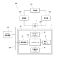
- FIG. 1 is a block diagram of an air conditioner system having an electric valve device according to an embodiment of the present invention
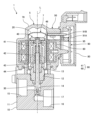
- FIG. FIG. 2 is a cross-sectional view of the motor-operated valve device of FIG. 1
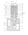
- FIG. 3 is a cross-sectional view of a valve body assembly included in the motor-operated valve device of FIG. 2
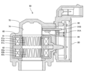
- FIG. 3 is a cross-sectional view of a stator unit included in the motor-operated valve device of FIG. 2
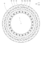
- FIG. 3 is a diagram showing a rotor and a stator that the motor-operated valve device of FIG. 2 has
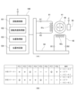
- 3 is a diagram for explaining a computer, a motor driver, a magnetic sensor, a permanent magnet, and a stepping motor that the motor-operated valve device of FIG.
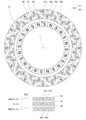
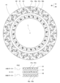
- FIG. 4 is a diagram schematically showing the positional relationship between the magnetic poles of the rotor and the pole teeth of the stator (when pulse P[1] is input);
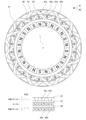
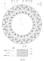
- FIG. 4 is a diagram schematically showing the positional relationship between the magnetic poles of the rotor and the pole teeth of the stator (when pulse P[2] is input);
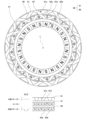
- FIG. 4 is a diagram schematically showing the positional relationship between the magnetic poles of the rotor and the pole teeth of the stator (when pulse P[3] is input);
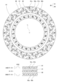
- FIG. 4 is a diagram schematically showing the positional relationship between the magnetic poles of the rotor and the pole teeth of the stator (when pulse P[4] is input);
- FIG. 4 is a diagram schematically showing the positional relationship between the magnetic poles of the rotor and the pole teeth of the stator (when pulse P[1] is input)
- FIG. 4 is a diagram schematically showing the positional relationship between the magnetic poles of the rotor and the pole teeth of the stator (when
- FIG. 4 is a diagram schematically showing the positional relationship between the magnetic poles of the rotor and the pole teeth of the stator (when pulse P[5] is input);
- FIG. 4 is a diagram schematically showing the positional relationship between the magnetic poles of the rotor and the pole teeth of the stator (when pulse P[6] is input);
- FIG. 4 is a diagram schematically showing the positional relationship between the magnetic poles of the rotor and the pole teeth of the stator (when pulse P[7] is input);
- FIG. 4 is a diagram schematically showing the positional relationship between the magnetic poles of the rotor and the pole teeth of the stator (when pulse P[8] is input);
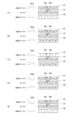
- FIG. 10 is a diagram for explaining the movement of the rotor when the stepping motor receives a pulse for rotating the rotor in the first direction in a state in which the rotation of the rotor in the first direction is restricted;
- FIG. 10 is a diagram for explaining the movement of the rotor when the stepping motor receives a pulse for rotating the rotor in the first direction in a state in which the rotation of the rotor in the first direction is restricted; (Continued from FIG. 15).
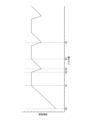
- 4 is a graph showing an example of changes in rotation angle of a rotor; It is a figure which shows an example of change pattern information.
- FIG. 1 A motor-operated valve device 1 according to an embodiment of the present invention will be described below with reference to FIGS. 1 to 21.
- FIG. 1 A motor-operated valve device 1 according to an embodiment of the present invention will be described below with reference to FIGS. 1 to 21.
- FIG. 1 is a block diagram of an air conditioner system having an electric valve device according to one embodiment of the present invention.
- 2 is a cross-sectional view of the motor-operated valve device of FIG. 1.
- FIG. 3 is a cross-sectional view of a valve body assembly included in the motor-operated valve device of FIG. 2.
- FIG. 4 is a cross-sectional view of a stator unit included in the motor-operated valve device of FIG. 2.
- FIG. FIG. 5 is a diagram showing a rotor and a stator that the motor-operated valve device of FIG. 2 has. In FIG. 5, the rotor and stator are shown schematically.
- FIG. 5 is a diagram showing a rotor and a stator that the motor-operated valve device of FIG. 2 has. In FIG. 5, the rotor and stator are shown schematically.
- FIG. 5 is a diagram showing a rotor and a stator that the motor-operated valve device of FIG. 2 has. In FIG. 5,
- FIG. 6 is a diagram for explaining the computer, motor driver, magnetic sensor, permanent magnet, and stepping motor (rotor, stator) that the motor-operated valve device of FIG. 2 has.
- FIG. 6A the computer, motor driver, magnetic sensor, permanent magnets, rotor and stator are shown schematically.
- FIG. 6B shows an example of correspondence between a plurality of pulses and drive currents supplied to the stator.
- 7 to 14 are diagrams schematically showing the positional relationship between the magnetic poles of the rotor and the pole teeth of the stator. 7 to 14 correspond to the input of pulses P[1] to P[8]. 7 to 14 schematically show rotors and stators.
- FIG. 15 and 16 are diagrams for explaining the movement of the rotor when the stepping motor receives a pulse to rotate the rotor in the first direction in a state where the rotation of the rotor in the first direction is restricted.
- FIG. 17 is a graph showing an example of changes in rotation angle when the rotor is rotated in the first direction.
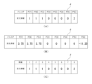
- FIG. 18 is a diagram showing an example of change pattern information.
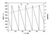
- FIG. 19 is a graph showing an example of signals output by the magnetic sensor.
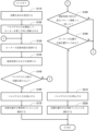
- 20 is a flowchart showing an example of an initialization operation executed by a computer included in the motor-operated valve device of FIG. 2.
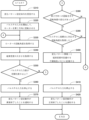
- FIG. 21 is a flowchart showing an example of a change pattern setting operation executed by a computer included in the motor-operated valve device of FIG. 2.
- FIG. 1 shows an example of an air conditioning system 200 mounted on a vehicle.
- This air conditioning system 200 has a compressor 201 , a condenser 202 , a motor-operated valve device 1 (a motor-operated valve 5 ), and an evaporator 203 which are connected in order via a pipe 205 .
- the electric valve device 1 is an expansion valve.
- the air conditioner system 200 has an air conditioner control device 210 .
- the air conditioner control device 210 is communicably connected to the electric valve device 1 .
- the air conditioner control device 210 controls the flow rate of refrigerant flowing through the pipe 205 using the electric valve device 1 .
- the motor-operated valve device 1 has a motor-operated valve 5 and a motor-operated valve control device 90 .
- the electric valve 5 has a valve body assembly 7 and a stator unit 50 .
- the valve body assembly 7 has a valve body 10 , a can 20 , a valve body 30 and a drive mechanism 40 .
- the valve body 10 is made of metal such as aluminum alloy, for example.
- the valve body 10 has a body portion 11 , a cylindrical portion 12 and a connection portion 13 .
- the body portion 11 has a rectangular parallelepiped shape.
- the cylindrical portion 12 protrudes from the upper surface of the body portion 11 .
- the cylindrical portion 12 is attached to the body portion 11 with a screw structure.
- the body portion 11 is provided with a valve chamber 14 , flow paths 15 and 16 , a valve port 17 and a valve seat 18 .
- the flow path 15 is connected to the valve chest 14 .
- the flow path 16 is connected to the valve chest 14 via the valve port 17 .
- a valve seat 18 surrounds the valve port 17 in the valve chamber 14 .
- the connecting portion 13 has an annular plate shape. The inner peripheral edge of the connecting portion 13 is joined to the upper portion of the cylindrical portion 12 .
- the can 20 is made of metal such as stainless steel.
- the can 20 has a cylindrical shape.
- the can 20 is open at its lower end and closed at its upper end.
- the lower end of the can 20 is joined to the outer peripheral edge of the connecting portion 13 .
- the valve body 30 has a first shaft portion 31 , a second shaft portion 32 , a valve portion 33 and a stepped portion 34 .
- the first shaft portion 31 has a cylindrical shape.
- the second shaft portion 32 has a cylindrical shape.
- the diameter of the second shaft portion 32 is smaller than the diameter of the first shaft portion 31 .
- the second shaft portion 32 is coaxially connected to the upper end of the first shaft portion 31 .
- the stepped portion 34 is an annular flat surface facing upward.
- the stepped portion 34 is arranged at a connecting portion between the first shaft portion 31 and the second shaft portion 32 .
- the valve portion 33 is coaxially connected to the lower end of the first shaft portion 31 .
- the valve portion 33 faces the valve port 17 .
- the drive mechanism 40 moves the valve body 30 in the direction of the axis L (vertical direction in FIGS. 2 and 3). The movement of the valve body 30 opens and closes the valve port 17 .
- the drive mechanism 40 has a rotor 41 , a valve stem holder 42 , a guide bush 43 and a stopper member 44 .
- the rotor 41 has a cylindrical shape.
- the outer diameter of rotor 41 is slightly smaller than the inner diameter of can 20 .
- the rotor 41 is arranged inside the can 20 .
- the rotor 41 is rotatable with respect to the valve body 10 and movable in the axis L direction.
- the rotor 41 has multiple N poles and multiple S poles.
- a plurality of N poles and a plurality of S poles are arranged on the outer peripheral surface of the rotor 41 .
- a plurality of N poles and a plurality of S poles extend in the axis L direction.
- the plurality of N poles and the plurality of S poles are alternately arranged at equal angular intervals in the circumferential direction.
- the rotor 41 has 12 N poles and 12 S poles.
- the angle between adjacent north and south poles is 15 degrees.
- the valve shaft holder 42 has a cylindrical shape.
- the valve stem holder 42 is open at its lower end and closed at its upper end.
- a support ring 45 is fixed to the upper wall portion 42 a of the valve shaft holder 42 .
- a support ring 45 connects the rotor 41 and the valve shaft holder 42 .
- the valve stem holder 42 rotates together with the rotor 41 .
- the valve stem holder 42 has a movable stopper 42s.
- the valve shaft holder 42 has a shaft hole 42b.
- the shaft hole 42 b is arranged in the upper wall portion 42 a of the valve shaft holder 42 .
- the second shaft portion 32 of the valve body 30 is arranged movably in the axis L direction in the shaft hole 42b.
- a push nut 35 for retaining is attached to the second shaft portion 32 .
- a washer 46 is arranged on the lower surface of the upper wall portion 42 a of the valve stem holder 42 .
- a valve closing spring 47 is arranged between the washer 46 and the step portion 34 of the valve body 30 .
- the valve closing spring 47 is a coil spring and pushes the valve body 30 toward the valve opening 17 .
- a female thread 42 c is formed on the inner peripheral surface of the valve stem holder 42 .
- the movable stopper 42 s is fixed with respect to the rotor 41 .
- the guide bush 43 has a base portion 43a and a support portion 43b.
- the base 43a has a cylindrical shape.
- the base portion 43 a is press-fitted into the fitting hole 12 a of the cylindrical portion 12 .
- the support portion 43b has a cylindrical shape.
- the outer diameter of the support portion 43b is smaller than the outer diameter of the base portion 43a.
- the inner diameter of the support portion 43b is the same as the inner diameter of the base portion 43a.
- the support portion 43b is coaxially connected to the upper end of the base portion 43a.
- a male thread 43c is formed on the outer peripheral surface of the support portion 43b.
- the male thread 43 c is screwed with the female thread 42 c of the valve shaft holder 42 .
- the first shaft portion 31 of the valve body 30 is arranged inside the guide bush 43 .
- the guide bush 43 supports the valve body 30 so as to be movable in the axis L direction.
- the stopper member 44 is attached to the base 43 a of the guide bush 43 .
- the stopper member 44 has a fixed stopper 44s.
- the fixed stopper 44 s is fixed to the valve body 10 .
- the permanent magnets 48 are arranged above the rotor 41 inside the can 20 .
- the permanent magnet 48 has an annular plate shape.
- the permanent magnet 48 has one north pole and one south pole, and the north pole and the south pole face each other in the radial direction.
- Permanent magnets 48 are attached to rotor 41 via fixtures 49 and support ring 45 .
- a permanent magnet 48 is arranged coaxially with the rotor 41 .
- the permanent magnet 48 rotates together with the rotor 41 and moves along the axis L direction together with the rotor 41 .
- the stator unit 50 has a stator 60, a housing 70, and a case 80.
- the stator 60 has a cylindrical shape.
- the stator 60 has an A-phase stator 61 and a B-phase stator 62 .
- the A-phase stator 61 has a plurality of claw pole-shaped pole teeth 61a and 61b on its inner periphery.
- the radially outer side of the A-phase stator 61 corresponds to the upper side, and the radially inner side corresponds to the lower side.
- the tip of the pole tooth 61a faces downward, and the tip of the pole tooth 61b faces upward.
- the pole teeth 61a and the pole teeth 61b are alternately arranged at equal angular intervals in the circumferential direction.
- the A-phase stator 61 has 12 pole teeth 61a and 12 pole teeth 61b.
- the angle between the adjacent pole teeth 61a and 61b is 15 degrees.
- the B-phase stator 62 has a plurality of claw pole-shaped pole teeth 62a, 62b on its inner periphery.
- the radially outer side of the B-phase stator 62 corresponds to the upper side, and the radially inner side corresponds to the lower side.
- the tip of the pole tooth 62a faces downward and the tip of the pole tooth 62b faces upward.
- the pole teeth 62a and the pole teeth 62b are alternately arranged at equal angular intervals in the circumferential direction.
- the B-phase stator 62 has 12 pole teeth 62a and 12 pole teeth 62b.
- the angle between the adjacent pole teeth 62a and 62b is 15 degrees.
- the A-phase stator 61 and the B-phase stator 62 are arranged coaxially.
- the A-phase stator 61 is in contact with the B-phase stator 62 .
- the angle between the pole teeth 61a of the A-phase stator 61 and the pole teeth 62a of the B-phase stator 62 that are adjacent to each other when viewed in the direction of the axis L is 7.5 degrees. That is, the B-phase stator 62 is at a position rotated about the axis L by 7.5 degrees with respect to the A-phase stator 61 from the position where the pole teeth 61a and the pole teeth 62a are aligned in the axis L direction.
- terminals A1 and A2 of the coil 61c of the A-phase stator 61 and terminals B1 and B2 of the coil 62c of the B-phase stator 62 are connected to the electric valve control device 90 (motor driver 94).
- the can 20 is arranged inside the stator 60 .
- a rotor 41 is arranged inside the can 20 .
- the stator 60 and rotor 41 constitute a stepping motor 66 .
- the rotor 41 is rotated by inputting pulses P (P[1] to P[8]) to the stepping motor 66 .
- the stator 60 of the stepping motor 66 is supplied with a drive current corresponding to the pulse P, thereby rotating the rotor 41 .
- the pulse P is input to the stepping motor 66 is synonymous with "the drive current corresponding to the pulse P is supplied to the stator 60 of the stepping motor 66".
- Pulses P[1] to P[8] are repeatedly input to stepping motor 66 in ascending or descending order.
- the pulses P[1] to P[8] are pulses P for one period, and are "a plurality of pulses P" that are repeatedly input to the stepping motor 66 in a predetermined order.
- the step angle of the stepping motor 66 is 3.75 degrees.
- Pulses P[1] to P[8] shown in FIG. 6B are sequentially input to the stepping motor 66 .
- 7 to 14 show examples of the positional relationship between the rotor 41 and the stator 60 when the pulses P[1] to P[8] are input. 7 to 14, in order to make it easier to grasp the positional relationship between the rotor 41 and the stator 60 (A-phase stator 61, B-phase stator 62), reference pole teeth 61a and reference magnetic poles (S poles) are marked (black circles).
- pulses P are repeatedly input to the stepping motor 66 in ascending order (in the order of pulses P[1] to P[8]).
- the rotor 41 rotates in the first direction, the rotor 41 and the valve stem holder 42 move downward due to the screw feeding action of the female thread 42c of the valve stem holder 42 and the male thread 43c of the guide bush 43 . That is, the rotor 41 approaches the valve port 17 .
- the permanent magnet 48 also moves downward together with the rotor 41 .
- the rotor 41 (valve shaft holder 42 ) pushes the valve body 30 downward via the valve closing spring 47 .
- the valve body 30 moves downward and the valve portion 33 contacts the valve seat 18 .
- the position of the rotor 41 at this time is the valve closing position Rc.
- the valve closing spring 47 is compressed and the rotor 41 and the valve stem holder 42 move further downward.
- the valve body 30 does not move downward.
- the movable stopper 42s of the valve shaft holder 42 comes into contact with the fixed stopper 44s of the stopper member 44, the rotation of the rotor 41 in the first direction is restricted.
- the position of the rotor 41 at this time is the reference position Rx.
- the movable stopper 42s and the fixed stopper 44s are a stopper mechanism ST that restricts the rotation of the rotor 41 in the first direction.
- FIGS. 15 to 17 A change in the rotation angle of the rotor 41 when the pulses P are input to the stepping motor 66 in ascending order while the rotation of the rotor 41 in the first direction is restricted will be described with reference to FIGS. 15 to 17.
- 15 and 16 in order to make it easier to grasp the positional relationship between the rotor 41 and the stator 60 (the A-phase stator 61 and the B-phase stator 62), reference pole teeth 61a and magnetic poles (S poles) are marked (black squares).
- the right side corresponds to the first direction and the left side corresponds to the second direction.
- the horizontal axis indicates the number of pulses input to the stepping motor 66 and the vertical axis indicates the rotation angle of the rotor 41 .
- the horizontal axis is scaled for each pulse.
- the vertical axis is scaled for each step angle. In FIG. 17, when the rotor 41 rotates in the first direction, the rotation angle increases, and when it rotates in the second direction,
- the rotor 41 rotates in the first direction and the rotation angle increases (N0 to N1 in FIG. 17). Then, for example, when the pulse P[1] is input to the stepping motor 66, the rotor 41 is positioned at the reference position Rx (N1 in FIGS. 15A and 17). At this time, the movable stopper 42s and the fixed stopper 44s are in contact with each other, and the rotation of the rotor 41 in the first direction is restricted.
- the rotor 41 rotates in the first direction by a step angle each time the pulse P is input. It is again positioned at the reference position Rx (FIGS. 16B-16D, N3-N4 in FIG. 17). Thereafter, according to the input of the pulse P, the rotation angle of the rotor 41 repeats the same change as in the period N1 to N4 in FIG.
- pulses P are applied to the stepping motor 66 in descending order (in order of pulses P[8] to P[1]). Enter repeatedly.
- the rotor 41 rotates in the second direction, the rotor 41 and the valve stem holder 42 move upward due to the screw feeding action of the female thread 42c of the valve stem holder 42 and the male thread 43c of the guide bushing 43 . That is, the rotor 41 leaves the valve port 17 .
- the permanent magnet 48 also moves upward together with the rotor 41 .
- the rotor 41 (valve shaft holder 42) pushes the push nut 35 upward.
- valve body 30 moves upward together with the push nut 35 to separate from the valve seat 18 . Further rotation of the rotor 41 in the second direction causes the rotor 41 to reach the fully open position Rz. The valve body 30 is the farthest from the valve port 17 when the rotor 41 is at the fully open position Rz.
- the housing 70 is made of synthetic resin.
- the housing 70 is molded by injection molding.
- Housing 70 accommodates stator 60 .
- the housing 70 may be integrally molded (insert molded) with the stator 60 .
- the stator 60 and the housing 70 may be manufactured separately and the stator 60 may be fitted inside the housing 70 .
- Housing 70 and stator 60 form an inner space 74 of stator unit 50 .
- the can 20 is inserted into the inner space 74 and the stator 60 is arranged on the outer peripheral surface of the can 20 .
- the case 80 is made of synthetic resin.
- the case 80 is arranged on the side of the housing 70 .
- Case 80 is joined to housing 70 .
- the valve port 17 the can 20, the valve body 30, the rotor 41, the valve shaft holder 42, the guide bush 43, the permanent magnet 48, the stator 60 (A phase stator 61, B phase stator 62)
- the axis coincides with the axis line L.
- the electric valve control device 90 has a main board 91A and a sub-board 91B.
- the main board 91A is accommodated in the case 80.
- the sub-board 91B is arranged across the housing 70 and the case 80 .
- the sub-board 91B is electrically connected to the main board 91A.
- the electric valve control device 90 has a nonvolatile memory 92, a communication device 93, a motor driver 94, a magnetic sensor 95, and a computer 100, as shown in FIG. These are mounted on the main board 91A and the sub-board 91B.
- the motor-operated valve control device 90 controls the motor-operated valve 5 based on commands from the air conditioner control device 210 .
- the non-volatile memory 92 stores data that must be retained even when the power is turned off.
- Non-volatile memory 92 is, for example, EEPROM or flash memory.
- the nonvolatile memory 92 stores the initialization number X, the change pattern information J, and the magnetic flux density determination value K.
- the initialization number X is the number of pulses input to the stepping motor 66 to position the rotor 41 at the reference position Rx.
- the initialization number X is set to a sufficient number so that the movable stopper 42s contacts the fixed stopper 44s when the rotor 41 is rotated in the first direction.
- the initialization number X is set based on the number of pulses (full stroke number) input to the stepping motor 66 when rotating the rotor 41 from the fully open position Rz to the reference position Rx. For the initialization number X, for example, a value obtained by multiplying the number of full strokes by 1.2 is set.
- the change pattern information J is information indicating changes in the rotation angle of the rotor 41 when the pulses P are input to the stepping motor 66 in ascending order while the rotor 41 is at the reference position Rx.
- a state in which the rotor 41 is at the reference position Rx is a state in which the rotation of the rotor 41 in the first direction is restricted by the stopper mechanism ST.
- the change pattern information J is stored in the non-volatile memory 92 at the time of shipment from the factory, for example.
- the change pattern information J is set based on the rotation angle of the magnetic field actually detected by the magnetic sensor 95 . In this embodiment, the change information is set corresponding to the pulses P[1] to P[8].
- the change pattern information J corresponds to a change pattern.
- FIG. 18A shows an example of change pattern information J in this embodiment.
- the variation pattern information J stores combinations of pulses P and variation information.
- the change information is information on changes in the rotation angle of the rotor 41 . In the change information, “1" indicates rotation in the first direction, “2" indicates rotation in the second direction, and “0” indicates no rotation (no change in rotation angle).
- “1" indicates rotation in the first direction
- “2" indicates rotation in the second direction
- 0” indicates no rotation (no change in rotation angle).
- the change information of the change pattern information J may include the rotation angle of the rotor 41 that changes corresponding to the pulse P.
- FIG. A positive angle indicates rotation in the first direction and a negative angle indicates rotation in the second direction.
- the change information of the change pattern information J does not have to correspond to the pulse P.
- the change pattern information J may include change information and its order.
- the change pattern information J may include at least change information indicating rotation in the second direction.
- the magnetic flux density determination value K is used to determine whether the rotor 41 is at the proximity position Rk or at a position closer to the reference position Rx than the proximity position Rk. Specifically, the magnetic flux density determination value K is set to a value corresponding to the magnitude of the magnetic flux density (the strength of the magnetic field) detected by the magnetic sensor 95 when the rotor 41 is positioned at the proximity position Rk. ing.
- the close position Rk is, for example, a position between the reference position Rx and the closed valve position Rc.
- the magnetic flux density determination value K is set based on the magnitude of the magnetic flux density actually detected by the magnetic sensor 95 .
- the magnetic flux density determination value K is stored, for example, in the nonvolatile memory 92 at the time of shipment from the factory.
- the communication device 93 is communicably connected to the air conditioner control device 210 via the wired communication bus 220 .
- the air conditioning system 200 employs, for example, a communication method such as Local Interconnect Network (LIN) or Controller Area Network (CAN). Note that the communication device 93 may be connected to the air conditioner control device 210 so as to be capable of wireless communication.
- LIN Local Interconnect Network
- CAN Controller Area Network
- the motor driver 94 supplies drive current to the stepping motor 66 based on the pulse P input from the computer 100.
- FIG. 6B shows an example of the correspondence between the pulse P and the drive current supplied by the motor driver 94. As shown in FIG. In FIG. 6B, (+) indicates the supply of drive current from terminal A1 to terminal A2 or from terminal B1 to terminal B2, and (-) indicates drive from terminal A2 to terminal A1. It indicates that a current or drive current is supplied from the terminal B2 to the terminal B1, and (0) indicates that no drive current is supplied.
- the magnetic sensor 95 is mounted on the sub-board 91B.
- the magnetic sensor 95 is arranged near the upper end of the can 20 .
- the magnetic sensor 95 laterally faces the permanent magnet 48 via the can 20 .
- the sub-board 91B may be arranged above the can 20, and the magnetic sensor 95 may face the permanent magnet 48 in the direction of the axis L with the can 20 interposed therebetween.
- the magnetic sensor 95 detects the magnetic field generated by the permanent magnets 48 attached to the rotor 41.
- the magnetic sensor 95 outputs a signal (rotation angle signal Sa) corresponding to the rotation angle of the magnetic field.
- the rotation angle signal Sa is a signal corresponding to the rotation angle of the rotor 41 .
- the magnetic sensor 95 is a rotation angle sensor that outputs a signal corresponding to the rotation angle of the rotor 41 .
- other types of sensors other than the magnetic sensor may be employed as the rotation angle sensor.
- the magnetic sensor 95 outputs a signal (magnetic flux density signal Sm) corresponding to the magnitude of the magnetic flux density.
- the magnitude of the magnetic flux density detected by the magnetic sensor 95 changes according to the position of the permanent magnet 48 (rotor 41) in the axis L direction.
- the magnitude of the magnetic flux density detected by the magnetic sensor 95 is smallest when the rotor 41 is at the reference position Rx, and is largest when the rotor 41 is at the fully open position Rz.
- the magnetic flux density signal Sm is a signal (position signal) corresponding to the position of the rotor 41 .
- the magnetic sensor 95 is a position sensor that outputs a signal corresponding to the position of the rotor 41 .
- other types of sensors than the magnetic sensor may be employed as the position sensor.
- the solid line is a graph showing the rotation angle signal Sa
- the dashed line is a graph showing the magnetic flux density signal Sm.
- the horizontal axis is the number of pulses.
- the vertical axis represents the angle data and magnetic flux density output by the magnetic sensor 95 .
- the value (angle data) indicated by the rotation angle signal Sa corresponds to 0 to 360 degrees.
- the value (magnitude of magnetic flux density) indicated by the magnetic flux density signal Sm decreases when the permanent magnet 48 moves downward, and increases when the permanent magnet 48 moves upward.
- the rotation angle signal Sa is a voltage value corresponding to the angle of the rotor 41.
- the computer 100 uses a value (angle data) obtained by A/D converting the rotation angle signal Sa.
- a rotation angle of the rotor 41 is calculated using the angle data.
- the computer 100 may use the rotation angle signal Sa (angle data) as information indicating the rotation angle of the rotor 41 .
- the magnetic flux density signal Sm is a voltage value corresponding to the position of the rotor 41 .
- the computer 100 uses the value obtained by A/D converting the magnetic flux density signal Sm as information indicating the position of the rotor 41 .
- the computer 100 is a microcomputer for embedded equipment in which a CPU, ROM, RAM, input/output interface, A/D converter, etc. are incorporated in one package.
- Computer 100 may include non-volatile memory 92 , communication device 93 and motor driver 94 .
- the computer 100 functions as a rotation control unit 101, a rotation angle acquisition unit 102, a position acquisition unit 103, and a position determination unit 104 by the CPU executing programs stored in the ROM.
- the rotation control unit 101 inputs a pulse P to the stepping motor 66 to rotate the rotor 41 in the first direction or the second direction. Specifically, rotation control unit 101 inputs pulses P[ 1 ] to P[ 8 ] to motor driver 94 based on the command received from air conditioner control device 210 .
- the motor driver 94 supplies drive currents to the coil 61c of the A-phase stator 61 and the coil 62c of the B-phase stator 62 according to the input pulses P[1] to P[8].
- the rotation angle acquisition unit 102 acquires the rotation angle of the rotor 41 . Specifically, the rotation angle acquisition unit 102 acquires the rotation angle of the rotor 41 based on the rotation angle signal Sa output by the magnetic sensor 95 each time the rotation control unit 101 inputs the pulse P to the stepping motor 66 .
- the position acquisition unit 103 acquires the position of the rotor 41 in the direction of the axis L. Specifically, the position acquisition unit 103 determines the magnitude of the magnetic flux density (the position of the rotor 41 ).
- the position determination unit 104 determines whether or not the rotor 41 is positioned at the reference position Rx. Specifically, the position determination unit 104 compares the change in the rotation angle of the rotor 41 acquired by the rotation angle acquisition unit 102 with the change pattern information J. FIG. Further, the position determination unit 104 compares the magnitude of the magnetic flux density acquired by the position acquisition unit 103 with the magnetic flux density determination value K. FIG. Then, the position determination unit 104 positions the rotor 41 at the reference position Rx when the change in the rotation angle of the rotor 41 matches the change pattern information J and the magnitude of the magnetic flux density is equal to or less than the magnetic flux density determination value K. determined to have been
- the electric valve control device 90 positions the rotor 41 at the reference position Rx by executing the initialization operation.
- the electric valve control device 90 (specifically, the computer 100) receives an initialization command from the air conditioner control device 210 (S110), it starts inputting pulses P (ascending order) to the stepping motor 66 to rotate the rotor 41. Rotate in a first direction (S120).
- the electric valve control device 90 functions as a rotation control section 101 .
- the drive current corresponding to the pulse P is supplied to the stator 60, and the rotor 41 rotates in the first direction.
- the electric valve control device 90 acquires the rotation angle of the rotor 41 based on the rotation angle signal Sa each time the pulse P is input (S130).
- the electric valve control device 90 functions as a rotation angle acquisition section 102 .
- the electric valve control device 90 acquires the magnitude of the magnetic flux density based on the magnetic flux density signal Sm each time the pulse P is input (S140).
- the electric valve control device 90 functions as a position acquisition section 103 .
- the motor-operated valve control device 90 stops inputting pulses P to the stepping motor 66 (S160). Then, the electric valve control device 90 determines that it cannot confirm that the rotor 41 is positioned at the reference position Rx, and notifies the air conditioner control device 210 that the initialization operation has ended abnormally (S170).
- the motor-operated valve control device 90 determines whether or not the change in the rotation angle of the rotor 41 matches the change pattern information J. Determine (S180).
- the electric valve control device 90 functions as a position determination section 104 . Specifically, the electric valve control device 90 acquires changes in the rotation angle of the rotor 41 with respect to the input of the eight most recent pulses P. Then, the motor-operated valve control device 90 determines whether or not the combination of the eight most recent pulses P and the change in rotation angle corresponding to each pulse P matches the combination of the pulse P and the change information in the change pattern information J. judge.
- the electric valve control device 90 moves the rotor 41 to the proximity position Rk or a position closer to the reference position Rx than the proximity position Rk. It is determined whether or not there is (S190).
- the electric valve control device 90 functions as a position determination section 104 . Specifically, the motor-operated valve control device 90 determines whether or not the magnitude of the magnetic flux density acquired according to the most recent input of the pulse P is the magnetic flux density determination value K or less.
- the motor-operated valve control device 90 determines that the position of the rotor 41 is at the proximity position Rk or closer to the reference position Rx than the proximity position Rk. After making a decision, the process returns to step S130.
- the motor-operated valve control device 90 stops inputting the pulse P to the stepping motor 66 (S160), and the rotor 41 moves to the reference position. It may be determined that the rotation in the first direction is restricted at a position other than Rx, and may be notified to the air conditioner control device 210 that the initialization operation has ended abnormally (S170).
- the electric valve control device 90 determines that the position of the rotor 41 is at the proximity position Rk or closer to the reference position Rx than the proximity position Rk. A determination is made and the input of the pulse P to the stepping motor 66 is stopped (S210). The motor-operated valve control device 90 generates a pulse P corresponding to non-rotating change information in the change pattern information J (pulses P[2], P[3], P[4], P[ 5]) as the last input, preferably stopping the input of the pulse P. Then, the motor-operated valve control device 90 determines that the rotor 41 is positioned at the reference position Rx, and notifies the air conditioner control device 210 of the normal completion of the initialization operation (S220).
- the operation (S140, S190) relating to the determination of the position of the rotor 41 may be omitted.
- an operation related to determining the position of the rotor 41 in the initialization operation for example, when the rotor 41 is restricted from rotating in the first direction at a position other than the reference position Rx due to clogging with foreign matter or a failure.
- the air conditioner control device 210 Upon receiving the notification that the initialization operation of the motor-operated valve 5 has been completed normally, the air conditioner control device 210 starts controlling the flow rate of the refrigerant flowing through the pipe 205 .
- the change pattern information J is sent to the motor-operated valve control device 90 to reset the change pattern information J in the motor-operated valve device 1 . Send configuration commands.
- the electric valve control device 90 sets the change pattern information J and the magnetic flux density determination value K by executing the change pattern setting operation.
- the electric valve control device 90 When the electric valve control device 90 receives the change pattern setting command from the air conditioner control device 210 (S310), it starts inputting pulses P (ascending order) to the stepping motor 66 to rotate the rotor 41 in the first direction ( S320). As a result, the drive current corresponding to the pulse P is supplied to the stator 60, and the rotor 41 rotates in the first direction.
- the electric valve control device 90 acquires the rotation angle of the rotor 41 based on the rotation angle signal Sa of the magnetic sensor 95 each time the pulse P is input (S330).
- the electric valve control device 90 acquires the magnitude of the magnetic flux density based on the magnetic flux density signal Sm of the magnetic sensor 95 each time the pulse P is input (S340).
- the motor-operated valve control device 90 stops inputting pulses P to the stepping motor 66 (S360). Then, the electric valve control device 90 determines that the change pattern information J and the magnetic flux density determination value K could not be set normally, and notifies the air conditioner control device 210 that the change pattern setting operation has ended abnormally (S370). .
- the motor-operated valve control device 90 determines whether the rotation angle of the rotor 41 indicating rotation in the second direction has changed. (S380).
- the change in the rotation angle of the rotor 41 indicating rotation in the second direction is, for example, the change in the rotation angle shown in the period N2-N3 in FIG.
- the electric valve control device 90 When the rotation angle of the rotor 41 indicating rotation in the second direction has changed (Y in S380), the electric valve control device 90 has acquired the rotation angle of the rotor 41 corresponding to one cycle of the pulse P. It is determined whether or not (S390).
- the rotation angle of the rotor 41 corresponding to one cycle of the pulse P is, for example, the rotation angle shown in the period from N3 to N5 in FIG.
- the motor-operated valve control device 90 includes eight pulses P (pulses P[1] to P[8]) after there is a change in the rotation angle of the rotor 41 indicating rotation in the second direction. ) is input to the stepping motor 66, and it is determined whether or not the rotation angle of the rotor 41 corresponding to each pulse P has been acquired.
- the electric valve control device 90 When the electric valve control device 90 acquires the rotation angle of the rotor 41 corresponding to one cycle of the pulse P (Y in S390), it generates change pattern information J based on the rotation angle and stores it in the nonvolatile memory 92.
- the electric valve control device 90 calculates the magnitude of the magnetic flux density when the rotor 41 is in the proximity position Rk based on the magnitude of the magnetic flux density acquired in response to the most recent input of the pulse P, and calculates the magnitude of the magnetic flux density is stored in the nonvolatile memory 92 as the magnetic flux density determination value K (S400).
- the electric valve control device 90 stops inputting the pulse P to the stepping motor 66 (S410). Then, the motor-operated valve control device 90 determines that the change pattern information J and the magnetic flux density determination value K have been set normally, and notifies the air conditioner control device 210 that the change pattern setting operation has been normally completed (S370).
- the air-conditioner control device 210 Upon receiving notification that the change pattern setting operation of the motor-operated valve 5 has been completed normally, the air-conditioner control device 210 transmits an initialization command to the motor-operated valve control device 90 .
- the air conditioner control device 210 stops the air conditioner system 200, causes the air conditioner system 200 to perform a degenerate operation, and so on. perform an action.
- the electric valve control device 90 executes the change pattern setting operation to set the change pattern information J.
- the motor-operated valve device 1 includes the motor-operated valve 5 and the motor-operated valve control device 90 that controls the motor-operated valve 5 .
- the motor-operated valve 5 includes a valve body 10 having a valve port 17, a stepping motor 66 having a rotor 41, and a rotor 41 rotating in a first direction approaches the valve port 17 and rotating in a second direction. and a stopper mechanism ST that restricts rotation of the rotor 41 in the first direction when the rotor 41 is at the reference position Rx.
- the electric valve control device 90 has a magnetic sensor 95 that outputs a signal (rotation angle signal Sa) corresponding to the rotation angle of the rotor 41 and a signal (magnetic flux density signal Sm) corresponding to the position of the rotor 41 .
- the electric valve control device 90 performs (1) start inputting the pulse P to the stepping motor 66 to rotate the rotor 41 in the first direction; (2) Every time a pulse P is input to the stepping motor 66, the rotation angle of the rotor 41 is acquired based on the rotation angle signal Sa of the magnetic sensor 95, and the rotor 41 is detected based on the magnetic flux density signal Sm of the magnetic sensor 95. get the position of (3)
- the change pattern information J includes a change in rotation angle indicating rotation in the second direction.
- Pulses P[1] to P[8] (that is, drive current) are repeatedly input to the stepping motor 66 in a predetermined order. Then, when the rotor 41 rotates in the first direction and reaches the reference position Rx, the motor-operated valve 5 enters a state in which rotation of the rotor 41 in the first direction is restricted. In this state, when pulses P[1] to P[8] are further input to the stepping motor 66, the input of a specific pulse P included in the pulses P[1] to P[8] causes the rotor 41 to move in the second direction.
- the rotor 41 rotates in the first direction due to the input of another specific pulse P included in the pulses P[1] to P[8], and the rotor 41 reaches the reference position Rx again. Therefore, by stopping the input of the pulse P to the stepping motor 66 in response to the detection of the change in the rotation angle of the rotor 41 indicating rotation in the second direction, the rotor 41 quickly reaches the reference position Rx. Initialization operations can be terminated. Therefore, the time required for the initialization operation of the motor-operated valve 5 can be shortened, and noise can be suppressed.
- the change pattern information J further includes a change in rotation angle indicating rotation in the first direction.
- the change pattern information J includes rotation angle changes corresponding to the pulses P[1] to P[8] repeatedly input to the stepping motor 66 in a predetermined order. By doing so, it is possible to more reliably determine that the rotor 41 is positioned at the reference position Rx.
- the motor-operated valve control device 90 inputs the pulse P to the stepping motor 66 to rotate the rotor 41 in the first direction.
- the rotation angle corresponding to the pulses P[1] to P[8] is obtained, and the change pattern information J is set based on the rotation angle.
- the electric valve control device 90 is configured so that the change in the rotation angle of the rotor 41 matches the preset change pattern information J, and the position of the rotor 41 is the preset proximity position Rk or the proximity position When the position is closer to the reference position Rx than Rk (the magnitude of the magnetic flux density is equal to or less than the magnetic flux density determination value K), the input of the pulse P to the stepping motor 66 is stopped.
- the present invention is not limited to such a configuration.
- the electric valve control device 90 does not determine the position of the rotor 41 (the magnitude of the magnetic flux density), but only determines the match between the change in the rotation angle of the rotor 41 and the change pattern information J, and the stepping motor 66 , the input of the pulse P may be stopped.
- the electric valve control device 90 may determine whether the change in the rotation angle signal Sa matches a preset change pattern.
- the electric valve control device 90 in the initialization operation, (1) start inputting the pulse P to the stepping motor 66 to rotate the rotor 41 in the first direction; (2) acquiring the rotation angle of the rotor 41 based on the rotation angle signal Sa of the magnetic sensor 95 each time the pulse P is input to the stepping motor 66; (3-1) stopping the input of the pulse P to the stepping motor 66 when a change in the rotation angle indicating rotation in the second direction is detected, or (3-2) Inputting the pulse P to the stepping motor 66 when a change in the rotation angle indicating rotation in the first direction is detected after detecting a change in the rotation angle indicating rotation in the second direction. You can stop it.
- the electric valve control device 90 in the initialization operation, (1) start inputting the pulse P to the stepping motor 66 to rotate the rotor 41 in the first direction; (2) Every time a pulse P is input to the stepping motor 66, the rotation angle of the rotor 41 is acquired based on the rotation angle signal Sa of the magnetic sensor 95, and the rotor 41 is detected based on the magnetic flux density signal Sm of the magnetic sensor 95.
- the stepping motor 66 stop inputting the pulse P to the (3-2) Detecting a change in the rotation angle indicating rotation in the first direction after detecting a change in the rotation angle indicating rotation in the second direction, and detecting the position of the rotor 41 in the proximity position Rk or The input of the pulse P to the stepping motor 66 may be stopped when the position is closer to the reference position Rx than the proximity position Rk.
- the magnetic sensor 95 detects the magnetic field generated by the permanent magnet 48, but the present invention is not limited to such a configuration.
- the permanent magnet 48 may be omitted and the magnetic sensor 95 may detect the magnetic field generated by the magnetic poles of the rotor 41 .
- the electric valve control device 90 sets the change pattern information J in response to receiving the change pattern setting command.
- the electric valve control device 90 may reset the change pattern information J when it determines that the rotor 41 is positioned at the reference position Rx in the initialization operation (S170 in FIG. 20).
- the motor-operated valve control device 90 performs one cycle of the pulse P from the time when the rotation angle of the rotor 41 indicating rotation in the second direction changes in the rotation angle of the rotor 41 acquired in the initialization operation.
- the rotation angle of the rotor 41 corresponding to minutes is held.
- the motor-operated valve control device 90 determines that it cannot confirm that the rotor 41 is positioned at the reference position Rx, it resets the change pattern information J based on the held rotation angle.
- each term indicating the shape of a member such as “cylindrical” or “cylindrical” is also used for a member substantially having the shape of the term.
- a “cylindrical member” includes a cylindrical member and a substantially cylindrical member.
Landscapes
- Engineering & Computer Science (AREA)
- General Engineering & Computer Science (AREA)
- Mechanical Engineering (AREA)
- Power Engineering (AREA)
- Electrically Driven Valve-Operating Means (AREA)
- Control Of Stepping Motors (AREA)
Abstract
Description
弁口を有する弁本体と、ローターを有するステッピングモーターと、前記ローターが第1方向に回転されると前記弁口に近づきかつ前記ローターが第2方向に回転されると前記弁口から離れる弁体と、前記ローターが基準位置にあるときに前記ローターの前記第1方向への回転を規制するストッパ機構と、を有する電動弁を制御する電動弁制御装置であって、
前記電動弁制御装置が、前記ローターの回転角度に応じた信号を出力する回転角度センサーを有し、
前記電動弁制御装置が、
(1)前記ステッピングモーターへのパルスの入力を開始して前記ローターを前記第1方向に回転させ、
(2)前記ステッピングモーターにパルスを入力する毎に前記回転角度センサーの信号に基づいて前記ローターの回転角度を取得し、
(3)前記回転角度の変化があらかじめ設定された変化パターンと一致したとき、前記ステッピングモーターへのパルスの入力を停止し、
前記変化パターンが、前記第2方向への回転を示す前記回転角度の変化を含むことを特徴とする。
弁口を有する弁本体と、ローターを有するステッピングモーターと、前記ローターが第1方向に回転されると前記弁口に近づきかつ前記ローターが第2方向に回転されると前記弁口から離れる弁体と、前記ローターが基準位置にあるときに前記ローターの前記第1方向への回転を規制するストッパ機構と、を有する電動弁を制御する電動弁制御装置であって、
前記電動弁制御装置が、前記ローターの回転角度に応じた信号を出力する回転角度センサーと、前記ローターの位置に応じた信号を出力する位置センサーと、を有し、
前記電動弁制御装置が、
(1)前記ステッピングモーターへのパルスの入力を開始して前記ローターを前記第1方向に回転させ、
(2)前記ステッピングモーターにパルスを入力する毎に、前記回転角度センサーの信号に基づいて前記ローターの回転角度を取得し、かつ、前記位置センサーの信号に基づいて前記ローターの位置を取得し、
(3)前記回転角度の変化があらかじめ設定された変化パターンと一致し、かつ、前記ローターの位置があらかじめ設定された近接位置または前記近接位置よりも前記基準位置に近い位置であるとき、前記ステッピングモーターへのパルスの入力を停止し、
前記変化パターンが、前記第2方向への回転を示す前記回転角度の変化を含むことを特徴とする。
前記変化パターンが、前記第1方向への回転を示す前記回転角度の変化をさらに含む、ことが好ましい。
前記変化パターンが、前記ステッピングモーターに所定の順番で繰り返し入力される複数個のパルスに対応する前記回転角度の変化を含む、ことが好ましい。
前記電動弁制御装置が、前記変化パターンを設定する動作において、前記ステッピングモーターにパルスを入力して前記ローターを前記第1方向に回転させているときに前記第2方向への回転を示す前記回転角度の変化を検出すると、前記複数個のパルスに対応する前記回転角度を取得し、当該回転角度に基づいて前記変化パターンを設定する、ことが好ましい。
弁口を有する弁本体と、ローターを有するステッピングモーターと、前記ローターが第1方向に回転されると前記弁口に近づきかつ前記ローターが第2方向に回転されると前記弁口から離れる弁体と、前記ローターが基準位置にあるときに前記ローターの前記第1方向への回転を規制するストッパ機構と、を有する電動弁を制御する電動弁制御装置であって、
前記電動弁制御装置が、前記ローターの回転角度に応じた信号を出力する回転角度センサーを有し、
前記電動弁制御装置が、
(1)前記ステッピングモーターへのパルスの入力を開始して前記ローターを前記第1方向に回転させ、
(2)前記ステッピングモーターにパルスを入力する毎に前記回転角度センサーの信号に基づいて前記ローターの回転角度を取得し、
(3-1)前記第2方向への回転を示す前記回転角度の変化を検出したとき、前記ステッピングモーターへのパルスの入力を停止し、または、
(3-2)前記第2方向への回転を示す前記回転角度の変化を検出したあとに、前記第1方向への回転を示す前記回転角度の変化を検出したとき、前記ステッピングモーターへのパルスの入力を停止する、ことを特徴とする。
弁口を有する弁本体と、ローターを有するステッピングモーターと、前記ローターが第1方向に回転されると前記弁口に近づきかつ前記ローターが第2方向に回転されると前記弁口から離れる弁体と、前記ローターが基準位置にあるときに前記ローターの前記第1方向への回転を規制するストッパ機構と、を有する電動弁を制御する電動弁制御装置であって、
前記電動弁制御装置が、前記ローターの回転角度に応じた信号を出力する回転角度センサーと、前記ローターの位置に応じた信号を出力する位置センサーと、を有し、
前記電動弁制御装置が、
(1)前記ステッピングモーターへのパルスの入力を開始して前記ローターを前記第1方向に回転させ、
(2)前記ステッピングモーターにパルスを入力する毎に、前記回転角度センサーの信号に基づいて前記ローターの回転角度を取得し、かつ、前記位置センサーの信号に基づいて前記ローターの位置を取得し、
(3-1)前記第2方向への回転を示す前記回転角度の変化を検出し、かつ、前記ローターの位置があらかじめ設定された近接位置または前記近接位置よりも前記基準位置に近い位置であるとき、前記ステッピングモーターへのパルスの入力を停止し、または、
(3-2)前記第2方向への回転を示す前記回転角度の変化を検出したあとに、前記第1方向への回転を示す前記回転角度の変化を検出し、かつ、前記ローターの位置が前記近接位置もしくは前記近接位置よりも前記基準位置に近い位置であるとき、前記ステッピングモーターへのパルスの入力を停止する、ことを特徴とする。
前記電動弁が、前記ローターに取り付けられた永久磁石を有し、
前記回転角度センサーが、前記永久磁石によって生じる磁場の回転角度に応じた信号を出力する、ことが好ましい。
前記電動弁が、前記ローターに取り付けられた永久磁石を有し、
前記ローターが、前記第1方向に回転されると前記弁口に近づきかつ前記第2方向に回転されると前記弁口から離れ、
前記回転角度センサーが、前記永久磁石によって生じる磁場の回転角度に応じた信号を出力し、
前記位置センサーが、前記磁場の強さに応じた信号を出力する、ことが好ましい。
弁口を有する弁本体と、ローターを有するステッピングモーターと、前記ローターが第1方向に回転されると前記弁口に近づきかつ前記ローターが第2方向に回転されると前記弁口から離れる弁体と、前記ローターが基準位置にあるときに前記ローターの前記第1方向への回転を規制するストッパ機構と、を有する電動弁を制御する電動弁制御装置であって、
前記電動弁制御装置が、前記ローターの回転角度に応じた信号(以下、「回転角度信号」という。)を出力する回転角度センサーを有し、
前記電動弁制御装置が、
(1)前記ステッピングモーターへのパルスの入力を開始して前記ローターを前記第1方向に回転させ、
(2)前記回転角度信号を取得し、
(3)前記回転角度信号の変化があらかじめ設定された変化パターンと一致したとき、前記ステッピングモーターへのパルスの入力を停止し、
前記変化パターンが、前記第2方向への回転を示す前記回転角度信号の変化を含むことを特徴とする。
弁口を有する弁本体と、ローターを有するステッピングモーターと、前記ローターが第1方向に回転されると前記弁口に近づきかつ前記ローターが第2方向に回転されると前記弁口から離れる弁体と、前記ローターが基準位置にあるときに前記ローターの前記第1方向への回転を規制するストッパ機構と、を有する電動弁を制御する電動弁制御装置であって、
前記電動弁制御装置が、前記ローターの回転角度に応じた信号(以下、「回転角度信号」という。)を出力する回転角度センサーと、前記ローターの位置に応じた信号(以下、「位置信号」という。)を出力する位置センサーと、を有し、
前記電動弁制御装置が、
(1)前記ステッピングモーターへのパルスの入力を開始して前記ローターを前記第1方向に回転させ、
(2)前記回転角度信号を取得し、かつ、前記位置信号を取得し、
(3)前記回転角度信号の変化があらかじめ設定された変化パターンと一致し、かつ、前記位置信号があらかじめ設定された近接位置または前記近接位置よりも前記基準位置に近い位置に対応する値であるとき、前記ステッピングモーターへのパルスの入力を停止し、
前記変化パターンが、前記第2方向への回転を示す前記回転角度信号の変化を含むことを特徴とする。
弁口を有する弁本体と、ローターを有するステッピングモーターと、前記ローターが第1方向に回転されると前記弁口に近づきかつ前記ローターが第2方向に回転されると前記弁口から離れる弁体と、前記ローターが基準位置にあるときに前記ローターの前記第1方向への回転を規制するストッパ機構と、を有する電動弁を制御する電動弁制御装置であって、
前記電動弁制御装置が、前記ローターの回転角度に応じた信号(以下、「回転角度信号」という。)を出力する回転角度センサーを有し、
前記電動弁制御装置が、
(1)前記ステッピングモーターへのパルスの入力を開始して前記ローターを前記第1方向に回転させ、
(2)前記回転角度信号を取得し、
(3-1)前記第2方向への回転を示す前記回転角度信号の変化を検出したとき、前記ステッピングモーターへのパルスの入力を停止し、または、
(3-2)前記第2方向への回転を示す前記回転角度信号の変化を検出したあとに、前記第1方向への回転を示す前記回転角度信号の変化を検出したとき、前記ステッピングモーターへのパルスの入力を停止する、ことを特徴とする。
弁口を有する弁本体と、ローターを有するステッピングモーターと、前記ローターが第1方向に回転されると前記弁口に近づきかつ前記ローターが第2方向に回転されると前記弁口から離れる弁体と、前記ローターが基準位置にあるときに前記ローターの前記第1方向への回転を規制するストッパ機構と、を有する電動弁を制御する電動弁制御装置であって、
前記電動弁制御装置が、前記ローターの回転角度に応じた信号(以下、「回転角度信号」という。)を出力する回転角度センサーと、前記ローターの位置に応じた信号(以下、「位置信号」という。)を出力する位置センサーと、を有し、
前記電動弁制御装置が、
(1)前記ステッピングモーターへのパルスの入力を開始して前記ローターを前記第1方向に回転させ、
(2)前記回転角度信号を取得し、かつ、前記位置信号を取得し、
(3-1)前記第2方向への回転を示す前記回転角度信号の変化を検出し、かつ、前記位置信号があらかじめ設定された近接位置または前記近接位置よりも前記基準位置に近い位置に対応する値であるとき、前記ステッピングモーターへのパルスの入力を停止し、または、
(3-2)前記第2方向への回転を示す前記回転角度信号の変化を検出したあとに、前記第1方向への回転を示す前記回転角度信号の変化を検出し、かつ、前記位置信号が前記近接位置もしくは前記近接位置よりも前記基準位置に近い位置に対応する値であるとき、前記ステッピングモーターへのパルスの入力を停止する、ことを特徴とする。
前記電動弁と、前記電動弁制御装置と、を有する。
(1)ステッピングモーターへのパルスの入力を開始してローターを第1方向に回転させる、
(2)ステッピングモーターにパルスを入力する毎に回転角度センサーの信号に基づいてローターの回転角度を取得する、
(3)回転角度の変化があらかじめ設定された変化パターンと一致したとき、ステッピングモーターへのパルスの入力を停止する。
そして、変化パターンが、第2方向への回転を示す回転角度の変化を含む。
(1)ステッピングモーターへのパルスの入力を開始してローターを第1方向に回転させる、
(2)ステッピングモーターにパルスを入力する毎に回転角度センサーの信号に基づいてローターの回転角度を取得する、
(3-1)第2方向への回転を示す回転角度の変化を検出したとき、ステッピングモーターへのパルスの入力を停止する、または、
(3-2)第2方向への回転を示す回転角度の変化を検出したあとに、第1方向への回転を示す回転角度の変化を検出したとき、ステッピングモーターへのパルスの入力を停止する。
(1)ステッピングモーター66へのパルスPの入力を開始してローター41を第1方向に回転させ、
(2)ステッピングモーター66にパルスPを入力する毎に、磁気センサー95の回転角度信号Saに基づいてローター41の回転角度を取得し、かつ、磁気センサー95の磁束密度信号Smに基づいてローター41の位置を取得し、
(3)ローター41の回転角度の変化が変化パターン情報Jと一致し、かつ、ローター41の位置が近接位置Rkまたは近接位置Rkよりも基準位置Rxに近い位置であるとき、ステッピングモーター66へのパルスPの入力を停止する。
変化パターン情報Jが、第2方向への回転を示す回転角度の変化を含む。
(1)ステッピングモーター66へのパルスPの入力を開始してローター41を第1方向に回転させ、
(2)ステッピングモーター66にパルスPを入力する毎に磁気センサー95の回転角度信号Saに基づいてローター41の回転角度を取得し、
(3-1)第2方向への回転を示す回転角度の変化を検出したとき、ステッピングモーター66へのパルスPの入力を停止し、または、
(3-2)第2方向への回転を示す回転角度の変化を検出したあとに、第1方向への回転を示す回転角度の変化を検出したとき、ステッピングモーター66へのパルスPの入力を停止する、ようにしてもよい。
(1)ステッピングモーター66へのパルスPの入力を開始してローター41を第1方向に回転させ、
(2)ステッピングモーター66にパルスPを入力する毎に、磁気センサー95の回転角度信号Saに基づいてローター41の回転角度を取得し、かつ、磁気センサー95の磁束密度信号Smに基づいてローター41の位置を取得し、
(3-1)第2方向への回転を示す回転角度の変化を検出し、かつ、ローター41の位置が近接位置Rkまたは近接位置Rkよりも基準位置Rxに近い位置であるとき、ステッピングモーター66へのパルスPの入力を停止し、または、
(3-2)第2方向への回転を示す回転角度の変化を検出したあとに、第1方向への回転を示す回転角度の変化を検出し、かつ、ローター41の位置が近接位置Rkもしくは近接位置Rkよりも基準位置Rxに近い位置であるとき、ステッピングモーター66へのパルスPの入力を停止する、ようにしてもよい。
Claims (14)
- 弁口を有する弁本体と、ローターを有するステッピングモーターと、前記ローターが第1方向に回転されると前記弁口に近づきかつ前記ローターが第2方向に回転されると前記弁口から離れる弁体と、前記ローターが基準位置にあるときに前記ローターの前記第1方向への回転を規制するストッパ機構と、を有する電動弁を制御する電動弁制御装置であって、
前記電動弁制御装置が、前記ローターの回転角度に応じた信号を出力する回転角度センサーを有し、
前記電動弁制御装置が、
(1)前記ステッピングモーターへのパルスの入力を開始して前記ローターを前記第1方向に回転させ、
(2)前記ステッピングモーターにパルスを入力する毎に前記回転角度センサーの信号に基づいて前記ローターの回転角度を取得し、
(3)前記回転角度の変化があらかじめ設定された変化パターンと一致したとき、前記ステッピングモーターへのパルスの入力を停止し、
前記変化パターンが、前記第2方向への回転を示す前記回転角度の変化を含むことを特徴とする電動弁制御装置。 - 弁口を有する弁本体と、ローターを有するステッピングモーターと、前記ローターが第1方向に回転されると前記弁口に近づきかつ前記ローターが第2方向に回転されると前記弁口から離れる弁体と、前記ローターが基準位置にあるときに前記ローターの前記第1方向への回転を規制するストッパ機構と、を有する電動弁を制御する電動弁制御装置であって、
前記電動弁制御装置が、前記ローターの回転角度に応じた信号を出力する回転角度センサーと、前記ローターの位置に応じた信号を出力する位置センサーと、を有し、
前記電動弁制御装置が、
(1)前記ステッピングモーターへのパルスの入力を開始して前記ローターを前記第1方向に回転させ、
(2)前記ステッピングモーターにパルスを入力する毎に、前記回転角度センサーの信号に基づいて前記ローターの回転角度を取得し、かつ、前記位置センサーの信号に基づいて前記ローターの位置を取得し、
(3)前記回転角度の変化があらかじめ設定された変化パターンと一致し、かつ、前記ローターの位置があらかじめ設定された近接位置または前記近接位置よりも前記基準位置に近い位置であるとき、前記ステッピングモーターへのパルスの入力を停止し、
前記変化パターンが、前記第2方向への回転を示す前記回転角度の変化を含むことを特徴とする電動弁制御装置。 - 前記変化パターンが、前記第1方向への回転を示す前記回転角度の変化をさらに含む、請求項1または請求項2に記載の電動弁制御装置。
- 前記変化パターンが、前記ステッピングモーターに所定の順番で繰り返し入力される複数個のパルスに対応する前記回転角度の変化を含む、請求項1または請求項2に記載の電動弁制御装置。
- 前記電動弁制御装置が、前記変化パターンを設定する動作において、前記ステッピングモーターにパルスを入力して前記ローターを前記第1方向に回転させているときに前記第2方向への回転を示す前記回転角度の変化を検出すると、前記複数個のパルスに対応する前記回転角度を取得し、当該回転角度に基づいて前記変化パターンを設定する、請求項4に記載の電動弁制御装置。
- 弁口を有する弁本体と、ローターを有するステッピングモーターと、前記ローターが第1方向に回転されると前記弁口に近づきかつ前記ローターが第2方向に回転されると前記弁口から離れる弁体と、前記ローターが基準位置にあるときに前記ローターの前記第1方向への回転を規制するストッパ機構と、を有する電動弁を制御する電動弁制御装置であって、
前記電動弁制御装置が、前記ローターの回転角度に応じた信号を出力する回転角度センサーを有し、
前記電動弁制御装置が、
(1)前記ステッピングモーターへのパルスの入力を開始して前記ローターを前記第1方向に回転させ、
(2)前記ステッピングモーターにパルスを入力する毎に前記回転角度センサーの信号に基づいて前記ローターの回転角度を取得し、
(3-1)前記第2方向への回転を示す前記回転角度の変化を検出したとき、前記ステッピングモーターへのパルスの入力を停止し、または、
(3-2)前記第2方向への回転を示す前記回転角度の変化を検出したあとに、前記第1方向への回転を示す前記回転角度の変化を検出したとき、前記ステッピングモーターへのパルスの入力を停止する、ことを特徴とする電動弁制御装置。 - 弁口を有する弁本体と、ローターを有するステッピングモーターと、前記ローターが第1方向に回転されると前記弁口に近づきかつ前記ローターが第2方向に回転されると前記弁口から離れる弁体と、前記ローターが基準位置にあるときに前記ローターの前記第1方向への回転を規制するストッパ機構と、を有する電動弁を制御する電動弁制御装置であって、
前記電動弁制御装置が、前記ローターの回転角度に応じた信号を出力する回転角度センサーと、前記ローターの位置に応じた信号を出力する位置センサーと、を有し、
前記電動弁制御装置が、
(1)前記ステッピングモーターへのパルスの入力を開始して前記ローターを前記第1方向に回転させ、
(2)前記ステッピングモーターにパルスを入力する毎に、前記回転角度センサーの信号に基づいて前記ローターの回転角度を取得し、かつ、前記位置センサーの信号に基づいて前記ローターの位置を取得し、
(3-1)前記第2方向への回転を示す前記回転角度の変化を検出し、かつ、前記ローターの位置があらかじめ設定された近接位置または前記近接位置よりも前記基準位置に近い位置であるとき、前記ステッピングモーターへのパルスの入力を停止し、または、
(3-2)前記第2方向への回転を示す前記回転角度の変化を検出したあとに、前記第1方向への回転を示す前記回転角度の変化を検出し、かつ、前記ローターの位置が前記近接位置もしくは前記近接位置よりも前記基準位置に近い位置であるとき、前記ステッピングモーターへのパルスの入力を停止する、ことを特徴とする電動弁制御装置。 - 前記電動弁が、前記ローターに取り付けられた永久磁石を有し、
前記回転角度センサーが、前記永久磁石によって生じる磁場の回転角度に応じた信号を出力する、請求項1、請求項2、請求項6または請求項7に記載の電動弁制御装置。 - 前記電動弁が、前記ローターに取り付けられた永久磁石を有し、
前記ローターが、前記第1方向に回転されると前記弁口に近づきかつ前記第2方向に回転されると前記弁口から離れ、
前記回転角度センサーが、前記永久磁石によって生じる磁場の回転角度に応じた信号を出力し、
前記位置センサーが、前記磁場の強さに応じた信号を出力する、請求項2または請求項7に記載の電動弁制御装置。 - 弁口を有する弁本体と、ローターを有するステッピングモーターと、前記ローターが第1方向に回転されると前記弁口に近づきかつ前記ローターが第2方向に回転されると前記弁口から離れる弁体と、前記ローターが基準位置にあるときに前記ローターの前記第1方向への回転を規制するストッパ機構と、を有する電動弁を制御する電動弁制御装置であって、
前記電動弁制御装置が、前記ローターの回転角度に応じた信号(以下、「回転角度信号」という。)を出力する回転角度センサーを有し、
前記電動弁制御装置が、
(1)前記ステッピングモーターへのパルスの入力を開始して前記ローターを前記第1方向に回転させ、
(2)前記回転角度信号を取得し、
(3)前記回転角度信号の変化があらかじめ設定された変化パターンと一致したとき、前記ステッピングモーターへのパルスの入力を停止し、
前記変化パターンが、前記第2方向への回転を示す前記回転角度信号の変化を含むことを特徴とする電動弁制御装置。 - 弁口を有する弁本体と、ローターを有するステッピングモーターと、前記ローターが第1方向に回転されると前記弁口に近づきかつ前記ローターが第2方向に回転されると前記弁口から離れる弁体と、前記ローターが基準位置にあるときに前記ローターの前記第1方向への回転を規制するストッパ機構と、を有する電動弁を制御する電動弁制御装置であって、
前記電動弁制御装置が、前記ローターの回転角度に応じた信号(以下、「回転角度信号」という。)を出力する回転角度センサーと、前記ローターの位置に応じた信号(以下、「位置信号」という。)を出力する位置センサーと、を有し、
前記電動弁制御装置が、
(1)前記ステッピングモーターへのパルスの入力を開始して前記ローターを前記第1方向に回転させ、
(2)前記回転角度信号を取得し、かつ、前記位置信号を取得し、
(3)前記回転角度信号の変化があらかじめ設定された変化パターンと一致し、かつ、前記位置信号があらかじめ設定された近接位置または前記近接位置よりも前記基準位置に近い位置に対応する値であるとき、前記ステッピングモーターへのパルスの入力を停止し、
前記変化パターンが、前記第2方向への回転を示す前記回転角度信号の変化を含むことを特徴とする電動弁制御装置。 - 弁口を有する弁本体と、ローターを有するステッピングモーターと、前記ローターが第1方向に回転されると前記弁口に近づきかつ前記ローターが第2方向に回転されると前記弁口から離れる弁体と、前記ローターが基準位置にあるときに前記ローターの前記第1方向への回転を規制するストッパ機構と、を有する電動弁を制御する電動弁制御装置であって、
前記電動弁制御装置が、前記ローターの回転角度に応じた信号(以下、「回転角度信号」という。)を出力する回転角度センサーを有し、
前記電動弁制御装置が、
(1)前記ステッピングモーターへのパルスの入力を開始して前記ローターを前記第1方向に回転させ、
(2)前記回転角度信号を取得し、
(3-1)前記第2方向への回転を示す前記回転角度信号の変化を検出したとき、前記ステッピングモーターへのパルスの入力を停止し、または、
(3-2)前記第2方向への回転を示す前記回転角度信号の変化を検出したあとに、前記第1方向への回転を示す前記回転角度信号の変化を検出したとき、前記ステッピングモーターへのパルスの入力を停止する、ことを特徴とする電動弁制御装置。 - 弁口を有する弁本体と、ローターを有するステッピングモーターと、前記ローターが第1方向に回転されると前記弁口に近づきかつ前記ローターが第2方向に回転されると前記弁口から離れる弁体と、前記ローターが基準位置にあるときに前記ローターの前記第1方向への回転を規制するストッパ機構と、を有する電動弁を制御する電動弁制御装置であって、
前記電動弁制御装置が、前記ローターの回転角度に応じた信号(以下、「回転角度信号」という。)を出力する回転角度センサーと、前記ローターの位置に応じた信号(以下、「位置信号」という。)を出力する位置センサーと、を有し、
前記電動弁制御装置が、
(1)前記ステッピングモーターへのパルスの入力を開始して前記ローターを前記第1方向に回転させ、
(2)前記回転角度信号を取得し、かつ、前記位置信号を取得し、
(3-1)前記第2方向への回転を示す前記回転角度信号の変化を検出し、かつ、前記位置信号があらかじめ設定された近接位置または前記近接位置よりも前記基準位置に近い位置に対応する値であるとき、前記ステッピングモーターへのパルスの入力を停止し、または、
(3-2)前記第2方向への回転を示す前記回転角度信号の変化を検出したあとに、前記第1方向への回転を示す前記回転角度信号の変化を検出し、かつ、前記位置信号が前記近接位置もしくは前記近接位置よりも前記基準位置に近い位置に対応する値であるとき、前記ステッピングモーターへのパルスの入力を停止する、ことを特徴とする電動弁制御装置。 - 前記電動弁と、請求項1、請求項2、請求項6、請求項7、請求項10、請求項11、請求項12または請求項13に記載の電動弁制御装置と、を有する電動弁装置。
Priority Applications (7)
| Application Number | Priority Date | Filing Date | Title |
|---|---|---|---|
| US18/832,839 US12504091B2 (en) | 2022-02-04 | 2022-12-28 | Electric valve control device and electric valve device |
| CN202280066922.5A CN118556170A (zh) | 2022-02-04 | 2022-12-28 | 电动阀控制装置及电动阀装置 |
| KR1020247012775A KR102963780B1 (ko) | 2022-02-04 | 2022-12-28 | 전동밸브 제어 장치 및 전동밸브 장치 |
| JP2023533379A JP7362180B1 (ja) | 2022-02-04 | 2022-12-28 | 電動弁制御装置および電動弁装置 |
| EP22925048.5A EP4474687A4 (en) | 2022-02-04 | 2022-12-28 | MOTORIZED VALVE CONTROL DEVICE AND MOTORIZED VALVE DEVICE |
| JP2023162857A JP7575132B2 (ja) | 2022-02-04 | 2023-09-26 | 電動弁制御装置および電動弁装置 |
| US19/392,670 US20260104104A1 (en) | 2022-02-04 | 2025-11-18 | Electric valve control device and electric valve device |
Applications Claiming Priority (2)
| Application Number | Priority Date | Filing Date | Title |
|---|---|---|---|
| JP2022-016471 | 2022-02-04 | ||
| JP2022016471 | 2022-02-04 |
Related Child Applications (2)
| Application Number | Title | Priority Date | Filing Date |
|---|---|---|---|
| US18/832,839 A-371-Of-International US12504091B2 (en) | 2022-02-04 | 2022-12-28 | Electric valve control device and electric valve device |
| US19/392,670 Continuation US20260104104A1 (en) | 2022-02-04 | 2025-11-18 | Electric valve control device and electric valve device |
Publications (1)
| Publication Number | Publication Date |
|---|---|
| WO2023149146A1 true WO2023149146A1 (ja) | 2023-08-10 |
Family
ID=87552259
Family Applications (1)
| Application Number | Title | Priority Date | Filing Date |
|---|---|---|---|
| PCT/JP2022/048468 Ceased WO2023149146A1 (ja) | 2022-02-04 | 2022-12-28 | 電動弁制御装置および電動弁装置 |
Country Status (6)
| Country | Link |
|---|---|
| US (2) | US12504091B2 (ja) |
| EP (1) | EP4474687A4 (ja) |
| JP (2) | JP7362180B1 (ja) |
| KR (1) | KR102963780B1 (ja) |
| CN (1) | CN118556170A (ja) |
| WO (1) | WO2023149146A1 (ja) |
Cited By (1)
| Publication number | Priority date | Publication date | Assignee | Title |
|---|---|---|---|---|
| WO2026033911A1 (ja) * | 2024-08-09 | 2026-02-12 | 株式会社不二工機 | 電動弁、及び温度調整システム |
Citations (3)
| Publication number | Priority date | Publication date | Assignee | Title |
|---|---|---|---|---|
| JP4028291B2 (ja) * | 2002-05-16 | 2007-12-26 | 株式会社鷺宮製作所 | 電動弁の駆動装置及び冷凍サイクル装置 |
| WO2019130928A1 (ja) | 2017-12-26 | 2019-07-04 | 株式会社不二工機 | 電動弁制御装置およびそれを備えた電動弁装置 |
| JP2021185326A (ja) * | 2020-07-27 | 2021-12-09 | 株式会社不二工機 | 電動弁 |
Family Cites Families (7)
| Publication number | Priority date | Publication date | Assignee | Title |
|---|---|---|---|---|
| JP3133233B2 (ja) * | 1995-07-06 | 2001-02-05 | 株式会社ユニシアジェックス | ステップモータの駆動制御方法 |
| US6667594B2 (en) * | 1999-11-23 | 2003-12-23 | Honeywell International Inc. | Determination of maximum travel of linear actuator |
| JP3735692B2 (ja) * | 2000-04-24 | 2006-01-18 | 日本電産サンキョー株式会社 | 開閉部材の駆動方法 |
| JP4835354B2 (ja) * | 2006-09-27 | 2011-12-14 | 三浦工業株式会社 | ニードル弁 |
| JP6741611B2 (ja) * | 2017-02-20 | 2020-08-19 | 株式会社不二工機 | 電動弁 |
| JP6826727B2 (ja) * | 2017-03-31 | 2021-02-10 | 株式会社不二工機 | 電動弁 |
| JP6518713B2 (ja) * | 2017-04-12 | 2019-05-22 | 株式会社不二工機 | 電動弁 |
-
2022
- 2022-12-28 US US18/832,839 patent/US12504091B2/en active Active
- 2022-12-28 KR KR1020247012775A patent/KR102963780B1/ko active Active
- 2022-12-28 WO PCT/JP2022/048468 patent/WO2023149146A1/ja not_active Ceased
- 2022-12-28 CN CN202280066922.5A patent/CN118556170A/zh active Pending
- 2022-12-28 JP JP2023533379A patent/JP7362180B1/ja active Active
- 2022-12-28 EP EP22925048.5A patent/EP4474687A4/en active Pending
-
2023
- 2023-09-26 JP JP2023162857A patent/JP7575132B2/ja active Active
-
2025
- 2025-11-18 US US19/392,670 patent/US20260104104A1/en active Pending
Patent Citations (3)
| Publication number | Priority date | Publication date | Assignee | Title |
|---|---|---|---|---|
| JP4028291B2 (ja) * | 2002-05-16 | 2007-12-26 | 株式会社鷺宮製作所 | 電動弁の駆動装置及び冷凍サイクル装置 |
| WO2019130928A1 (ja) | 2017-12-26 | 2019-07-04 | 株式会社不二工機 | 電動弁制御装置およびそれを備えた電動弁装置 |
| JP2021185326A (ja) * | 2020-07-27 | 2021-12-09 | 株式会社不二工機 | 電動弁 |
Non-Patent Citations (1)
| Title |
|---|
| See also references of EP4474687A4 |
Cited By (1)
| Publication number | Priority date | Publication date | Assignee | Title |
|---|---|---|---|---|
| WO2026033911A1 (ja) * | 2024-08-09 | 2026-02-12 | 株式会社不二工機 | 電動弁、及び温度調整システム |
Also Published As
| Publication number | Publication date |
|---|---|
| US20250172218A1 (en) | 2025-05-29 |
| JP2023175865A (ja) | 2023-12-12 |
| KR102963780B1 (ko) | 2026-05-12 |
| EP4474687A4 (en) | 2026-03-18 |
| JPWO2023149146A1 (ja) | 2023-08-10 |
| US12504091B2 (en) | 2025-12-23 |
| JP7575132B2 (ja) | 2024-10-29 |
| CN118556170A (zh) | 2024-08-27 |
| US20260104104A1 (en) | 2026-04-16 |
| KR20240055890A (ko) | 2024-04-29 |
| JP7362180B1 (ja) | 2023-10-17 |
| EP4474687A1 (en) | 2024-12-11 |
Similar Documents
| Publication | Publication Date | Title |
|---|---|---|
| KR102818706B1 (ko) | 전동밸브 제어 장치 및 전동밸브 장치 | |
| JP7768597B2 (ja) | 電動弁制御装置および電動弁装置、ならびに、電動弁の制御方法 | |
| US20260104104A1 (en) | Electric valve control device and electric valve device | |
| EP4534878A1 (en) | Motor-operated valve control device and motor-operated valve device | |
| WO2023090107A1 (ja) | 電動弁制御装置および電動弁装置 | |
| JP2023031233A (ja) | 電動弁、その制御方法、およびその製造方法 | |
| JP7710741B2 (ja) | 電動弁制御装置および電動弁装置、ならびに、電動弁の制御方法 | |
| JP7837598B2 (ja) | 電動弁制御装置および電動弁装置、ならびに電動弁の制御方法 | |
| JP7555645B2 (ja) | 電動弁制御装置および電動弁装置 | |
| JP7609417B2 (ja) | 電動弁制御装置 | |
| JP7718728B2 (ja) | 電動弁制御装置および電動弁装置、ならびに、電動弁の制御方法 | |
| JP7730605B2 (ja) | 電動弁制御装置および電動弁装置、ならびに、電動弁の状態判定方法 | |
| WO2024202317A1 (ja) | 電動弁制御装置および電動弁装置、ならびに、電動弁の制御方法 | |
| WO2025187110A1 (ja) | 電動弁制御装置および電動弁装置、ならびに電動弁の負荷検出方法 | |
| WO2025120915A1 (ja) | 電動弁制御装置および電動弁装置、ならびに電動弁の状態判定方法 |
Legal Events
| Date | Code | Title | Description |
|---|---|---|---|
| WWE | Wipo information: entry into national phase |
Ref document number: 2023533379 Country of ref document: JP |
|
| 121 | Ep: the epo has been informed by wipo that ep was designated in this application |
Ref document number: 22925048 Country of ref document: EP Kind code of ref document: A1 |
|
| WWE | Wipo information: entry into national phase |
Ref document number: 202280066922.5 Country of ref document: CN |
|
| ENP | Entry into the national phase |
Ref document number: 20247012775 Country of ref document: KR Kind code of ref document: A |
|
| WWE | Wipo information: entry into national phase |
Ref document number: 18832839 Country of ref document: US |
|
| WWE | Wipo information: entry into national phase |
Ref document number: 2022925048 Country of ref document: EP |
|
| NENP | Non-entry into the national phase |
Ref country code: DE |
|
| ENP | Entry into the national phase |
Ref document number: 2022925048 Country of ref document: EP Effective date: 20240904 |
|
| WWP | Wipo information: published in national office |
Ref document number: 18832839 Country of ref document: US |