WO2023149167A1 - ガス発生器 - Google Patents
ガス発生器 Download PDFInfo
- Publication number
- WO2023149167A1 WO2023149167A1 PCT/JP2023/000773 JP2023000773W WO2023149167A1 WO 2023149167 A1 WO2023149167 A1 WO 2023149167A1 JP 2023000773 W JP2023000773 W JP 2023000773W WO 2023149167 A1 WO2023149167 A1 WO 2023149167A1
- Authority
- WO
- WIPO (PCT)
- Prior art keywords
- generating agent
- gas generating
- housing
- gas
- storage chamber
- Prior art date
- Legal status (The legal status is an assumption and is not a legal conclusion. Google has not performed a legal analysis and makes no representation as to the accuracy of the status listed.)
- Ceased
Links
Images



Classifications
-
- B—PERFORMING OPERATIONS; TRANSPORTING
- B60—VEHICLES IN GENERAL
- B60R—VEHICLES, VEHICLE FITTINGS, OR VEHICLE PARTS, NOT OTHERWISE PROVIDED FOR
- B60R21/00—Arrangements or fittings on vehicles for protecting or preventing injuries to occupants or pedestrians in case of accidents or other traffic risks
- B60R21/02—Occupant safety arrangements or fittings, e.g. crash pads
- B60R21/16—Inflatable occupant restraints or confinements designed to inflate upon impact or impending impact, e.g. air bags
- B60R21/26—Inflatable occupant restraints or confinements designed to inflate upon impact or impending impact, e.g. air bags characterised by the inflation fluid source or means to control inflation fluid flow
- B60R21/264—Inflatable occupant restraints or confinements designed to inflate upon impact or impending impact, e.g. air bags characterised by the inflation fluid source or means to control inflation fluid flow using instantaneous generation of gas, e.g. pyrotechnic
- B60R21/2644—Inflatable occupant restraints or confinements designed to inflate upon impact or impending impact, e.g. air bags characterised by the inflation fluid source or means to control inflation fluid flow using instantaneous generation of gas, e.g. pyrotechnic using only solid reacting substances, e.g. pellets, powder
-
- B—PERFORMING OPERATIONS; TRANSPORTING
- B60—VEHICLES IN GENERAL
- B60R—VEHICLES, VEHICLE FITTINGS, OR VEHICLE PARTS, NOT OTHERWISE PROVIDED FOR
- B60R21/00—Arrangements or fittings on vehicles for protecting or preventing injuries to occupants or pedestrians in case of accidents or other traffic risks
- B60R21/02—Occupant safety arrangements or fittings, e.g. crash pads
- B60R21/16—Inflatable occupant restraints or confinements designed to inflate upon impact or impending impact, e.g. air bags
- B60R21/26—Inflatable occupant restraints or confinements designed to inflate upon impact or impending impact, e.g. air bags characterised by the inflation fluid source or means to control inflation fluid flow
- B60R2021/26011—Inflatable occupant restraints or confinements designed to inflate upon impact or impending impact, e.g. air bags characterised by the inflation fluid source or means to control inflation fluid flow using a filter through which the inflation gas passes
-
- B—PERFORMING OPERATIONS; TRANSPORTING
- B60—VEHICLES IN GENERAL
- B60R—VEHICLES, VEHICLE FITTINGS, OR VEHICLE PARTS, NOT OTHERWISE PROVIDED FOR
- B60R21/00—Arrangements or fittings on vehicles for protecting or preventing injuries to occupants or pedestrians in case of accidents or other traffic risks
- B60R21/02—Occupant safety arrangements or fittings, e.g. crash pads
- B60R21/16—Inflatable occupant restraints or confinements designed to inflate upon impact or impending impact, e.g. air bags
- B60R21/26—Inflatable occupant restraints or confinements designed to inflate upon impact or impending impact, e.g. air bags characterised by the inflation fluid source or means to control inflation fluid flow
- B60R2021/26029—Ignitors
- B60R2021/26041—Ignitors of elongated shape
-
- B—PERFORMING OPERATIONS; TRANSPORTING
- B60—VEHICLES IN GENERAL
- B60R—VEHICLES, VEHICLE FITTINGS, OR VEHICLE PARTS, NOT OTHERWISE PROVIDED FOR
- B60R21/00—Arrangements or fittings on vehicles for protecting or preventing injuries to occupants or pedestrians in case of accidents or other traffic risks
- B60R21/02—Occupant safety arrangements or fittings, e.g. crash pads
- B60R21/16—Inflatable occupant restraints or confinements designed to inflate upon impact or impending impact, e.g. air bags
- B60R21/26—Inflatable occupant restraints or confinements designed to inflate upon impact or impending impact, e.g. air bags characterised by the inflation fluid source or means to control inflation fluid flow
- B60R21/264—Inflatable occupant restraints or confinements designed to inflate upon impact or impending impact, e.g. air bags characterised by the inflation fluid source or means to control inflation fluid flow using instantaneous generation of gas, e.g. pyrotechnic
- B60R21/2644—Inflatable occupant restraints or confinements designed to inflate upon impact or impending impact, e.g. air bags characterised by the inflation fluid source or means to control inflation fluid flow using instantaneous generation of gas, e.g. pyrotechnic using only solid reacting substances, e.g. pellets, powder
- B60R2021/2648—Inflatable occupant restraints or confinements designed to inflate upon impact or impending impact, e.g. air bags characterised by the inflation fluid source or means to control inflation fluid flow using instantaneous generation of gas, e.g. pyrotechnic using only solid reacting substances, e.g. pellets, powder comprising a plurality of combustion chambers or sub-chambers
-
- B—PERFORMING OPERATIONS; TRANSPORTING
- B60—VEHICLES IN GENERAL
- B60R—VEHICLES, VEHICLE FITTINGS, OR VEHICLE PARTS, NOT OTHERWISE PROVIDED FOR
- B60R21/00—Arrangements or fittings on vehicles for protecting or preventing injuries to occupants or pedestrians in case of accidents or other traffic risks
- B60R21/02—Occupant safety arrangements or fittings, e.g. crash pads
- B60R21/16—Inflatable occupant restraints or confinements designed to inflate upon impact or impending impact, e.g. air bags
- B60R21/26—Inflatable occupant restraints or confinements designed to inflate upon impact or impending impact, e.g. air bags characterised by the inflation fluid source or means to control inflation fluid flow
- B60R21/264—Inflatable occupant restraints or confinements designed to inflate upon impact or impending impact, e.g. air bags characterised by the inflation fluid source or means to control inflation fluid flow using instantaneous generation of gas, e.g. pyrotechnic
- B60R21/2644—Inflatable occupant restraints or confinements designed to inflate upon impact or impending impact, e.g. air bags characterised by the inflation fluid source or means to control inflation fluid flow using instantaneous generation of gas, e.g. pyrotechnic using only solid reacting substances, e.g. pellets, powder
- B60R21/2646—Inflatable occupant restraints or confinements designed to inflate upon impact or impending impact, e.g. air bags characterised by the inflation fluid source or means to control inflation fluid flow using instantaneous generation of gas, e.g. pyrotechnic using only solid reacting substances, e.g. pellets, powder the reacting substances being supported by the inflatable member walls, or by a flexible support within it
Definitions
- the present invention relates to a gas generator incorporated in an airbag device as an occupant protection device installed in an automobile or the like, and more particularly to a so-called cylinder-type gas generator having a long columnar outer shape suitable for incorporation in a side airbag device or the like. Concerning vessels.
- Airbag devices which are occupant protection devices, have been widely used from the viewpoint of protecting the occupants of automobiles.
- Airbag systems are installed to protect passengers from the impact that occurs in the event of a vehicle collision. By inflating and deploying the airbag instantaneously in the event of a vehicle collision, the airbag acts as a cushion for the passenger. It accepts the body.
- the gas generator is incorporated in this airbag system, and when a vehicle or other vehicle collides, an igniter is ignited by electricity from the control unit, and the flame generated in the igniter burns the gas generating agent to instantaneously generate a large amount of gas. , the device that inflates and deploys the airbag.
- Cylinder-type gas generators have an elongated cylindrical outer shape and are suitably incorporated in side airbag devices, curtain airbag devices, knee airbag devices, seat cushion airbag devices, and the like.
- an igniter is assembled to one end of a housing in the axial direction, and a gas generating agent storage chamber containing a gas generating agent is provided on the one end side of the housing.
- a filter chamber in which a filter is arranged is provided on the other end side of the housing, and a gas ejection port is provided in the peripheral wall portion of the housing that defines the filter chamber.
- gas is generated inside the housing by burning the gas generating agent with the operation of the igniter, and after the generated gas passes through the inside of the filter, the gas It will be ejected to the outside through the ejection port.
- Patent Documents disclosing this type of cylinder-type gas generator include, for example, Japanese Patent Application Laid-Open No. 2007-314102 (Patent Document 1).
- the pressure in the space inside the housing during operation must be set within a range where the gas generating agent can stably and sustainably burn. Although it is essential to lower it to a considerable extent, it is not easy to achieve this by devising the structure of the gas generator.
- the present invention has been made in view of such problems, and provides a gas generator that not only realizes stable operation, but also reduces weight and manufacturing costs through structural improvements. intended to provide
- a gas generator includes a housing, a partition member, an igniter, and a coil spring.
- the housing consists of a long cylindrical member with one end and the other end closed in the axial direction, and contains a gas generating agent storage chamber containing a gas generating agent and a filter chamber containing a filter. included in The partition member is arranged such that the gas generating agent storage chamber is formed at a position on the one end side of the housing, and the filter chamber is formed at a position on the other end side of the housing. It partitions the space inside the in the axial direction.
- the igniter is attached to the one end of the housing for burning the gas generating agent.
- the coil spring is accommodated in the gas generating agent storage chamber by being interposed between the partition member and the gas generating agent, and the gas generating agent is moved while separating the gas generating agent from the partition member. is urged toward the one end of the housing to fix the gas generating agent inside the gas generating agent storage chamber.
- the volume of the gas generating agent storage chamber is set to V1
- the coil spring is arranged so that the inside of the gas generating agent storage chamber is a space in which the gas generating agent is not arranged. It satisfies the condition of 0.05 ⁇ V2/V1 ⁇ 0.32, where V2 is the volume of the filling space.
- the igniter may have an ignition section containing an ignition charge. preferably facing the gas generant.
- the coil spring is positioned at the cylindrical portion located on the partition member side and at the end portion of the cylindrical portion on the gas generating agent side, thereby generating the gas. and a pressing portion that presses the agent toward the one end side of the housing.
- the partition member includes a partition wall portion arranged perpendicular to the axial direction of the housing, and a partition wall portion extending from the peripheral edge of the partition wall portion toward the one end portion side of the housing.
- the axial end portion of the coil spring located on the other end side of the housing is preferably inserted at least inside the partition member.
- FIG. 1 is a schematic diagram of a cylinder-type gas generator according to an embodiment
- FIG. 2 is an enlarged cross-sectional view of the vicinity of an igniter of the cylinder-type gas generator shown in FIG. 1.
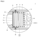
- FIG. 2 is an enlarged cross-sectional view of the vicinity of a partition member of the cylinder-type gas generator shown in FIG. 1.
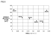
- FIG. 4 is a table summarizing test conditions and test results of a verification test; It is a graph which shows the test result of a verification test.
- FIG. 1 is a schematic diagram of a cylinder-type gas generator according to an embodiment.
- 2 and 3 are an enlarged cross-sectional view near the igniter and an enlarged cross-sectional view near the partition member of the cylindrical gas generator shown in FIG. 1, respectively.
- FIG. 1 the configuration of a cylinder-type gas generator 1 according to the present embodiment will be described with reference to FIGS. 1 to 3.
- FIG. 1 the configuration of a cylinder-type gas generator 1 according to the present embodiment will be described with reference to FIGS. 1 to 3.
- the cylinder-type gas generator 1 has a long columnar outer shape, and has a long cylindrical housing with one end and the other axially located end closed. are doing.
- the housing includes a housing body 10 , a holder assembly 20 and a closure member 30 .
- the holder assembly 20 and the closing member 30, the igniter 40, the partition member 50, the gas generating agent 60, the coil spring 70, the filter 80 and the like are accommodated as internal components. ing. Further, inside the housing, the gas generating agent storage chamber S1 in which the gas generating agent 60 and the coil spring 70 among the internal components described above are stored, and the filter chamber S2 in which the filter 80 is arranged are located. .
- the housing main body 10 constitutes the peripheral wall of the housing, and consists of a long cylindrical member with openings formed at both ends in the axial direction.
- the holder assembly 20 is a tubular member having a through-hole-shaped hollow opening extending in a direction parallel to the axial direction of the housing body 10, and has a holder portion 20A and a connector portion 20B which will be described later.
- the blocking member 30 is made of a substantially disk-shaped member.
- the housing body 10 may be made of a metal member such as stainless steel, iron steel, aluminum alloy, or stainless alloy, or may be a press formed by pressing a rolled steel plate typified by SPCE into a cylindrical shape. It may be configured by a molded product. Further, the housing body 10 may be composed of an electric resistance welded tube typified by STKM.
- the housing body 10 when the housing body 10 is composed of a press-formed product of rolled steel plate or an electric resistance welded pipe, the housing body 10 can be manufactured at a lower cost and more easily than when a member made of metal such as stainless steel or iron steel is used. can be formed, and a significant weight reduction is possible.
- the holder portion 20A and the closing member 30 of the holder assembly 20 are made of metal members such as stainless steel, steel, aluminum alloy, and stainless alloy.
- the holder assembly 20 is fixed to the housing body 10 so as to close one open end of the housing body 10 in the axial direction. Specifically, in a state in which the holder assembly 20 is inserted into the one open end of the housing body 10, a predetermined position of the housing body 10 is radially inwardly reduced toward the holder assembly 20. The holder assembly 20 is crimped and fixed to the housing body 10 by reducing the diameter of another predetermined position of the housing body 10 toward the vicinity of the holder assembly 20 and radially inward. ing. As a result, one axial end of the housing is formed by the holder assembly 20 . The details of the caulking fixation will be described later.
- the closing member 30 is fixed to the housing body 10 so as to close the other open end of the housing body 10 in the axial direction. Specifically, in a state in which the closing member 30 is inserted into the other open end of the housing body 10 , a predetermined position of the housing body 10 is radially inwardly reduced toward the vicinity of the closing member 30 . The closing member 30 is crimped and fixed to the housing body 10 by being pressed. As a result, the other axial end of the housing is formed by the closing member 30 . The details of the caulking fixation will also be described later.
- caulking methods are so-called eight-way caulking methods in which the diameter of the housing main body 10 is substantially uniformly reduced radially inward.
- the housing body 10 is provided with the crimped portions 12 to 14 .
- the housing body 10, the holder assembly 20, and the closing member 30 come into direct contact with each other, thereby preventing any gaps from occurring therebetween.
- the assembly structure of the holder assembly 20 and the closing member 30 with respect to the housing body 10 is not limited to the assembly structure described above (details will be described later), and other assembly structures may be employed. good too.
- the housing main body 10 and the closing member 30 may be configured as one member having a cylindrical shape with a bottom, instead of being separated.
- the igniter 40 is supported by the holder assembly 20 and assembled to the above-described one axial end of the housing.
- the igniter 40 is for burning the gas generating agent 60, and is installed so as to face the space inside the housing.
- the igniter 40 is for generating flame and is also called a squib.
- the igniter 40 includes a base portion 41 , an ignition portion 42 and a pair of terminal pins 43 .
- the base portion 41 is a portion that holds the ignition portion 42 and the pair of terminal pins 43 and is also a portion that is fixed to the holder assembly 20 .
- the base 41 holds the pair of terminal pins 43 through which they are inserted.
- the ignition part 42 contains therein an ignition charge that generates a flame by igniting and burning during operation, and a resistor (bridge wire) for igniting the ignition charge.
- a pair of terminal pins 43 are connected to the ignition portion 42 to ignite the ignition charge.
- the ignition part 42 includes a cup-shaped squib cup, and the above-described resistor is attached so as to connect the tips of a pair of terminal pins 43 inserted into the squib cup.
- the above-described resistor is attached so as to connect the tips of a pair of terminal pins 43 inserted into the squib cup.
- a nichrome wire, a resistance wire made of an alloy containing platinum and tungsten, or the like is generally used. Potassium chlorate), lead tricinate, and the like are used.
- a predetermined amount of current flows through the resistor via the terminal pin 43 .
- Joule heat is generated in the resistor, and the ignition charge starts burning.
- the hot, hot particles produced by the combustion rupture the squib cup containing the igniter charge.
- the time from when the current flows through the resistor until the igniter 40 is activated is generally 2 milliseconds or less when the nichrome wire is used as the resistor.
- the igniter 40 is fixed to the holder assembly 20 with its ignition part 42 protruding toward the interior of the housing and a part of the igniter 40 positioned inside the above-described hollow opening of the holder assembly 20. It is As a result, the ignition part 42 of the igniter 40 is located on the side of the gas generating agent storage chamber S1, and the terminal pin 43 is located on the opposite side of the gas generating agent storage chamber S1.
- the holder assembly 20 includes a metal holder portion 20A located on the side of the gas generating agent storage chamber S1 and a resin connector portion located on the side opposite to the gas generating agent storage chamber S1. 20B.
- the holder assembly 20 is configured as an integrated component by previously assembling the holder portion 20A and the connector portion 20B to each other, and this is attached to one of the open ends of the housing body 10 described above.
- the holder portion 20A is composed of a flat, substantially disk-shaped member having a through portion extending along the axial direction at its central portion. and an annular protrusion 22 projecting outwardly from the surface.
- the holder part 20A is inserted into the housing body 10 so that its axial direction is parallel to the axial direction of the housing body 10.
- the through portion provided in the holder portion 20A defines a part of the above-described hollow opening of the holder assembly 20, and the annular protrusion 22 extends along the radial direction of the housing body 10. It protrudes from the first trunk portion 21 .
- the above-described annular protrusion 22 is provided at the end of the first body 21 on the side of the gas generating agent storage chamber S1.
- the holder portion 20A is a member for receiving and holding the igniter 40.
- the holder portion 20A has a recessed accommodation portion 23a at its axial end on the side of the gas generating agent accommodation chamber S1. have.
- the accommodation portion 23a communicates with a through portion provided in the holder portion 20A.
- a crimped portion 23b is provided at the end portion of the holder portion 20A on the side of the gas generating agent storage chamber S1 so as to surround the storage portion 23a.
- the crimped portion 23b is a portion for crimping and fixing the igniter 40 to the holder portion 20A.
- the igniter 40 is fixed to the holder portion 20A with its base portion 41 housed in the housing portion 23a of the holder portion 20A. Specifically, the base portion 41 is inserted into the housing portion 23a of the holder portion 20A, and the base portion 41 is abutted against the bottom surface of the housing portion 23a. Thus, the igniter 40 is fixed to the holder portion 20A. Thereby, the igniter 40 is held by the holder portion 20A.
- a seal member 27 made of an O-ring or the like is interposed between the holder portion 20A and the igniter 40, so that the gap between the holder portion 20A and the igniter 40 is closed by the seal member 27.
- the gap is sealed by being embedded. Therefore, by configuring in this way, it is possible to ensure the airtightness of the portion.
- the fixing method of the igniter 40 is not limited to the fixing method using the crimped portion 23b described above, and other fixing methods may be used.
- the connector portion 20B is composed of a substantially cylindrical member having a through portion extending in the axial direction at its central portion. and a cylindrical portion 25 extending from one end along the axial direction.
- the connector portion 20B is inserted into the housing body 10 so that its axial direction is parallel to the axial direction of the housing body 10.
- the through portion provided in the connector portion 20B defines a part of the above-described hollow opening of the holder assembly 20, and the tubular portion 25 extends from the second body portion 24 to the gas generating agent. It extends toward the accommodation room S1 side.
- the holder portion 20A described above is fixed by being press-fitted into the connector portion 20B. More specifically, the first body portion 21 of the holder portion 20A is press-fitted into the cylindrical portion 25 of the connector portion 20B, and the first body portion 21 and the cylindrical portion 25 are brought into pressure contact with each other, whereby these holders are held together.
- the portion 20A and the connector portion 20B are fixed so as not to be easily separated.
- the connector portion 20B is for receiving a connector connected to the terminal pin 43 of the igniter 40.
- a terminal pin 43 of the igniter 40 is arranged inside the connector portion 20B.
- the through portion provided in the connector portion 20B described above constitutes a portion for receiving this connection connector.
- the igniter 40 must be electrically connected to an external control unit (not shown) for a vehicle or the like. are usually harnessed.
- a male connector is attached to the tip of this harness, and the connector section 20B must be provided with a female connector that can be connected to this male connector.
- the through portion provided in the connector portion 20B constitutes this female connector.
- the connector portion 20B also functions as a member that ensures airtightness between the housing body 10 and the holder portion 20A.
- a portion for ensuring airtightness between the housing body 10 and the holder portion 20A is mainly exhibited by the cylindrical portion 25 of the connector portion 20B.
- the tubular portion 25 is inserted into the opening end of the housing body 10 and externally inserted into the first trunk portion 21 of the holder portion 20A.
- the first body portion 21 of the holder portion 20A and the cylindrical portion of the connector portion 20B extend from the radially inner side to the radially outer side of the housing body 10.
- These parts are arranged in the order of the part 25 and the housing body 10 . That is, the first trunk portion 21 is surrounded by the cylindrical portion 25 , and the cylindrical portion 25 is surrounded by the housing body 10 .
- a portion of the housing body 10 corresponding to the tubular portion 25 (that is, a portion covering the tubular portion 25) is provided with a crimped portion 12 whose diameter is reduced radially inward.
- the connector made of a resin member is formed by the crimped portion 12 of the housing body 10 made of a metal member and the first trunk portion 21 of the holder portion 20A made of a metal member.
- the tubular portion 25 of the portion 20 ⁇ /b>B is sandwiched between them, thereby sealing the gap between the housing body 10 and the first trunk portion 21 with the tubular portion 25 .
- the tubular portion 25 is sandwiched between the housing main body 10 and the first trunk portion 21, so that the tubular portion 25 is compressed under the load. Deformation occurs. As a result, the tubular portion 25 and the housing main body 10 are brought into close contact with each other, and the tubular portion 25 and the first trunk portion 21 are brought into close contact with each other.
- the cylindrical portion 25 is interposed between the housing body 10 and the first body portion 21 while being in close contact with the housing body 10 and the first body portion 21, so that the gap described above is eliminated. Sealing can be achieved. Therefore, by configuring in this way, it is possible to ensure the airtightness of the portion.
- the material of the connector portion 20B is not particularly limited, but may be, for example, 6 nylon, 66 nylon, and nylon resins such as those filled with glass filler, polyacetal (POM), and the like.
- resin polycarbonate (PC) resin, polyphenylene sulfide (PPS) resin, polybutylene terephthalate (PBT) resin, and the like can be preferably used.
- annular protrusion 22 is provided at a position closer to the gas generating agent storage chamber S1 than the first body portion 21 is. Therefore, the annular protrusion 22 also functions as a stopper that prevents the holder assembly 20 from falling out of the housing body 10 .
- the function of the annular protrusion 22 as a stopper is exhibited not only during manufacture of the cylindrical gas generator 1 and during non-operation, but also during operation when pressure is applied due to an increase in the internal pressure of the gas generating agent storage chamber S1. It is also demonstrated.
- the inner diameter of the cylindrical portion 25 is larger than the inner diameter of the second body portion 24, and the inner diameter of the second body portion 24 is connected to the connector portion 20B.
- An annular stepped surface 26 connecting the peripheral surface and the inner peripheral surface of the tubular portion 25 is provided.
- the holder portion 20A and the connector portion 20B can be fixed by pressing the holder portion 20A into the connector portion 20B as described above, and furthermore, the axial direction of the housing body 10 can be fixed. Positioning of the holder portion 20A and the connector portion 20B can be performed with high accuracy along the .
- the above-described female connector is connected to the axial end surface of the first barrel portion 21 and the inner circumference of the second barrel portion 24 located on the side opposite to the gas generating agent storage chamber S1. It will be defined by the surface and the
- a partition member 50 is arranged at a predetermined position in the space inside the housing.
- the partition member 50 is a member for partitioning the space inside the housing into the gas generating agent storage chamber S1 and the filter chamber S2 in the axial direction.
- the partition member 50 has a cylindrical shape with a bottom, and is made of a metal member such as stainless steel, iron steel, aluminum alloy, or stainless alloy.
- the partition member 50 includes a flat plate-like partition wall portion 51 arranged perpendicular to the axial direction of the housing body 10 and a tubular plate erected from the peripheral edge of the partition wall portion 51 toward the gas generating agent storage chamber S1 side. and an annular wall portion 52 having a shape.
- the partition member 50 is arranged such that the outer main surface of the partition wall portion 51 is in contact with the filter 80 , and the outer peripheral surface of the annular wall portion 52 is in contact with the inner peripheral surface of the housing body 10 .
- a score 51 a is provided on the main surface of the partition wall 51 that contacts the filter 80 .
- the score 51a is for breaking the partition wall 51 and forming an opening as the internal pressure of the gas generating agent storage chamber S1 rises due to combustion of the gas generating agent 60.
- the score 51a It is composed of a plurality of intersecting grooves.
- the score 51 a is provided in a portion of the filter 80 facing the hollow portion 81 .
- the partition member 50 is fixed by being inserted into the housing body 10 and joined to the housing body 10 . More specifically, the partition member 50 is press-fitted into the housing body 10 and fixed by welding at or near the contact portion between the annular wall portion 52 of the partition member 50 and the housing body 10 . ing.
- a welded portion 90 extending along the circumferential direction of the housing body 10 is formed in the housing body 10 and the partition member 50 corresponding to the portion where the partition member 50 is inserted. Electron beam welding, laser welding, resistance welding, or the like can be suitably used for welding the partition member 50 and the housing body 10 together.
- the method of fixing the partition member 50 to the housing main body 10 is not limited to the above-described fixing method using press-fitting and welding, and other fixing methods may be used. In this case, airtightness between the partition member 50 and the housing body 10 can be ensured by providing O-rings, seal tapes, or the like at appropriate positions.
- the space that is, the gas generating agent storage chamber S1 sandwiched between the holder assembly 20 and the partition member 50 in the space inside the housing contains a gas generating agent 60, A coil spring 70 and a combustion control member 45 are arranged.
- the combustion control member 45 is arranged on the side where the holder assembly 20 is located (that is, the one end side of the gas generating agent storage chamber S1 in the axial direction of the housing), and the coil spring 70 is It is arranged on the side where the partition member 50 is located (that is, on the other end side of the gas generating agent storage chamber S1 in the axial direction of the housing). Also, the gas generating agent 60 is arranged between the combustion control member 45 and the coil spring 70 .
- the gas generating agent 60 is an agent that is ignited by thermal particles generated by the operation of the igniter 40 and combusts to generate gas.
- the gas generating agent 60 it is preferable to use a non-azide gas generating agent, and the gas generating agent 60 is generally configured as a compact containing a fuel, an oxidant, and an additive.
- triazole derivatives for example, triazole derivatives, tetrazole derivatives, guanidine derivatives, azodicarbonamide derivatives, hydrazine derivatives, etc. or combinations thereof are used.
- nitroguanidine, guanidine nitrate, cyanoguanidine, 5-aminotetrazole and the like are preferably used.
- oxidizing agents include basic metal salts such as basic copper nitrate and basic copper carbonate, perchlorates such as ammonium perchlorate and potassium perchlorate, alkali metals, alkaline earth metals, transition metals, and ammonia.
- basic metal salts such as basic copper nitrate and basic copper carbonate
- perchlorates such as ammonium perchlorate and potassium perchlorate
- alkali metals alkaline earth metals, transition metals, and ammonia.
- Nitrates and the like containing cations selected from are utilized.
- nitrates for example, sodium nitrate, potassium nitrate and the like are preferably used.
- Additives include binders, slag forming agents, and combustion modifiers.
- binder organic binders such as metal salts of carboxymethyl cellulose and stearates, and inorganic binders such as synthetic hydrotalcite and acid clay can be preferably used.
- slag forming agent silicon nitride, silica, acid clay, etc. can be suitably used.
- Metal oxides, ferrosilicon, activated carbon, graphite and the like can be suitably used as combustion modifiers.
- the shape of the molded body of the gas generating agent 60 includes various shapes such as granules, pellets, cylinders, etc., and discs.
- a perforated shaped body having through holes inside the shaped body for example, a single-hole cylindrical shape, a porous cylindrical shape, etc.
- These shapes are preferably selected appropriately according to the specifications of the airbag device in which the cylindrical gas generator 1 is incorporated. It is preferable to select the optimum shape according to the specifications, such as selecting .
- it is preferable to appropriately select the size and filling amount of the compact in consideration of the linear burning velocity, pressure index, etc. of the gas generating agent 60.
- the coil spring 70 is provided for the purpose of preventing the gas generating agent 60, which is a molded body, from being pulverized by vibration or the like. 72.
- the cylindrical portion 71 is composed of a spring-like portion in which a metal wire is spirally wound, and is arranged so that one end thereof abuts against the partition wall portion 51 of the partition member 50 .
- the pressing portion 72 is provided at the other end of the cylindrical portion 71.
- metal wires are arranged substantially parallel with a predetermined interval, or metal wires are arranged spirally with a predetermined interval. As a result, it is configured to have a substantially disk-like shape as a whole. This pressing portion 72 is in contact with the gas generating agent 60 .
- the coil spring 70 is compressed by being sandwiched between the partition member 50 and the gas generating agent 60 . Therefore, the gas generating agent 60 is elastically biased by the coil spring 70 toward the holder assembly 20 side (that is, the above-described one end portion side of the housing). It is prevented from moving inside the chamber S1. Therefore, by configuring in this manner, it is possible to prevent the gas generating agent 60 formed of a molded body from being pulverized by vibration or the like.
- the coil spring 70 when the coil spring 70 is assembled, the coil spring 70 is sandwiched and compressed by the partition member 50 and the gas generating agent 60, and as a result, the dimensional variations of various components housed inside the housing may occur. It can also be absorbed by
- the combustion control member 45 is for efficiently guiding the hot particles generated by the igniter 40 to the gas generating agent 60 during operation of the cylinder-type gas generator 1 .
- the combustion control member 45 has a substantially cylindrical shape, and is externally fitted on the ignition section 42 so as to surround the ignition section 42 by covering the peripheral surface of the ignition section 42 .
- the squib cup that defines the outer surface of the ignition portion 42 bursts, the squib cup is located on the gas generating agent 60 side of the squib cup.
- An opening is formed mainly at the leading end portion, and along with this, the advancing direction of the thermal particles generated in the ignition portion 42 is narrowed in the axial direction of the housing.
- the combustion control member 45 by arranging the combustion control member 45 so as to fill the gap between the housing body 10 and the ignition portion 42, the combustion control member 45 is positioned radially outside the ignition portion 42.
- the combustion control member 45 prevents the thermal particles generated in the ignition portion 42 from advancing radially outward, and as a result, the traveling direction of the thermal particles is constricted in the axial direction.
- the outer peripheral surface of the combustion control member 45 is provided with an annular concave portion 45a extending along the circumferential direction.
- This annular recessed portion 45 a is a portion for fixing the combustion control member 45 to the housing body 10 .
- the portion of the housing body 10 corresponding to the annular recess 45a is contracted radially inward to fill the annular recess 45a.
- the engagement causes the combustion control member 45 to be crimped and fixed to the housing body 10 .
- the crimped portion 13 is provided on the portion of the housing body 10 corresponding to the annular recess 45a.
- the holder assembly 20 can be fixed to the housing body 10 as well. That is, by providing a pair of crimped portions 12 and 13 so as to sandwich an annular protrusion 22 provided on the holder portion 20A of the holder assembly 20, the holder portion 20A extends along the axial direction of the housing body 10. Since movement is restricted, the holder assembly 20 is thereby firmly fixed to the housing body 10 .
- a filter 80 is arranged in a space sandwiched between the closing member 30 and the partition member 50 (that is, the filter chamber S2) in the space inside the housing.
- the filter 80 is a cylindrical member having a hollow portion 81 extending in a direction parallel to the axial direction of the housing body 10, and one axial end face of the filter 80 is in contact with the closing member 30. is in contact with the partition wall portion 51 of the partition member 50 .
- the filter 80 functions as a cooling means for cooling the gas by removing high-temperature heat from the gas when the gas generated by the combustion of the gas generating agent 60 passes through the filter 80. It also functions as a removing means for removing slag (residue) and the like contained in.
- the filter 80 it is possible to preferably use a filter composed of an aggregate of metal wires or metal nets made of stainless steel, steel, or the like. Specifically, a knitted wire mesh, a plain-woven wire mesh, an aggregate of crimp-woven metal wire rods, or a product obtained by pressing these together can be used.
- the filter 80 a wound perforated metal plate or the like can be used.
- the perforated metal plate may be, for example, an expanded metal obtained by cutting a metal plate in a zigzag pattern and expanding the cuts to form holes to form a mesh, or a metal plate with holes and A hook metal or the like can be used by flattening the burrs formed on the periphery of the hole by crushing them.
- the portion of the housing body 10 defining the filter chamber S2 is provided with a plurality of gas ejection ports 11 along the circumferential direction and the axial direction. These multiple gas ejection ports 11 are for leading out the gas after passing through the filter 80 to the outside of the housing.
- the closing member 30 is fixed to the housing body 10 by crimping portions 14 provided at predetermined positions of the housing body 10 .
- a portion of the housing body 10 adjacent to the closing member 30, which is located on the side opposite to the side where the filter chamber S2 is located when viewed from the closing member 30, has a radially inwardly extending portion.
- a crimped portion 14 having a reduced diameter is provided, and the closing member 30 is sandwiched between the crimped portion 14 and the filter 80 .
- the movement of the closing member 30 along the axial direction of the housing body 10 is restricted, so that the closing member 30 is firmly fixed to the housing body 10.
- the collision is detected by collision detection means separately provided in the vehicle.
- the igniter 40 is activated by energization from a control unit separately provided in the vehicle.
- the combustion of the igniter charge and/or transfer charge increases pressure within the igniter section 42, which causes the squib cup of the igniter section 42 to open and release the igniter charge and/or transfer charge.
- Thermal particles generated by the combustion of the transfer charge flow out of the ignition section 42 .
- the hot particles reaching the gas generating agent 60 burn the gas generating agent 60, thereby generating a large amount of gas in the gas generating agent storage chamber S1.
- the pressure in the gas generating agent storage chamber S1 rises, and when the internal pressure of the gas generating agent storage chamber S1 reaches a predetermined pressure, the portion of the partition member 50 provided with the score 51a is broken. occurs. As a result, an opening is formed in the partition member 50 at a portion facing the hollow portion 81 of the filter 80, and the gas generating agent storage chamber S1 and the filter chamber S2 communicate with each other through the opening. Become.
- the gas generated in the gas generating agent storage chamber S1 flows into the filter chamber S2 through the opening formed in the partition member 50.
- the gas that has flowed into the filter chamber S2 flows in the hollow portion 81 of the filter 80 along the axial direction and then changes direction in the radial direction to flow through the inside of the filter 80 .
- heat is removed by the filter 80 to cool the gas, and slag contained in the gas is removed by the filter 80 .
- the gas After passing through the filter 80 , the gas is ejected to the outside of the housing through the gas ejection port 11 provided in the housing body 10 .
- the ejected gas is introduced into an airbag provided adjacent to the cylinder-type gas generator 1 to inflate and deploy the airbag.
- the coil spring 70 is interposed between the partition member 50 and the gas generating agent 60 as described above. are arranged in the gas generating agent storage chamber S1.
- the gas generating agent 60 is positioned away from the partition member 50, and the gas generating agent storage chamber S1 is a space in which the gas generating agent 60 is not disposed by arranging the coil spring 70.
- the combustion control member 45 is arranged in addition to the gas generating agent 60 and the coil spring 70 in the gas generating agent storage chamber S1. substantially functions as a pressure partition, the space in which the combustion control member 45 is arranged is not included in the gas generating agent storage chamber S1.
- the volume of the gas generating agent storage chamber S1 described above (that is, the sum of the volume of the non-filled space S1A and the volume of the filled space S1B described above) is V1
- the volume ratio V2/V1 which is the ratio of these V1 and V2 satisfies the condition of 0.05 ⁇ V2/V1 ⁇ 0.32.
- the pressure in the space inside the housing (that is, the internal pressure in the combustion chamber) is adjusted to the gas generating agent 60 during operation. can be reduced to a considerable extent within a range in which stable and sustained combustion is possible.
- the said conditions are derived based on the result of the verification test mentioned later.
- a cavity of a predetermined volume is provided in the partition member 50 side portion of the gas generating agent storage chamber S1. Therefore, when the cylinder-type gas generator 1 is in operation, it is possible to suppress the unburned gas generating agent 60 from gathering in this portion. Therefore, the opening formed in the partition member 50 will not be blocked by the unburned gas generating agent 60 due to the breakage of the partition wall portion 51, so that the flow resistance of the gas in this portion can be reduced. become. Therefore, the gas generated in the gas generating agent storage chamber S1 flows more smoothly into the filter chamber S2, and an increase in the internal pressure of the combustion chamber can be effectively suppressed.
- the above-mentioned volume ratio V2/V1 satisfies the condition of V2/V1 ⁇ 0.32, thereby making it possible to suppress the occurrence of such an internal pressure increase mechanism, thereby increasing the internal pressure of the combustion chamber. This means that the increase can be effectively suppressed.
- the cylinder-type gas generator 1 by satisfying the above-described condition that the volume ratio V2/V1 is 0.05 ⁇ V2/V1 ⁇ 0.32, stable operation can be realized.
- the thickness of the housing since it is possible to effectively suppress the increase in the internal pressure of the combustion chamber during operation, it is possible to reduce the thickness of the housing accordingly. As a result, the weight of the cylinder-type gas generator 1 can be reduced and the manufacturing cost can be reduced by the above-described structural improvement.
- the ignition part 42 of the igniter 40 is configured to directly face the gas generating agent 60 without interposing other members.
- the gas generating agent 60 starts burning early when the igniter 40 is activated, so the ignitability is improved immediately after the igniter 40 is activated and the thermal power generated at that time is improved. It will be possible to increase the
- the diameter of the hollow portion 81 of the filter 80 (for example, to set the diameter to 11 mm or more). With this configuration, it is possible to increase the area of the opening formed in the partition member 50 during operation, so that the gas generated in the gas generating agent storage chamber S1 can flow more smoothly into the filter chamber. Since it flows into S2, it becomes possible to further effectively suppress the increase in the internal pressure of the combustion chamber.
- the axial end of the coil spring 70 located on the filter chamber S2 side is configured to be inserted into the partition member 50. It is In this way, when the cylindrical gas generator 1 is manufactured, it is possible to attach the partition member 50 together with the coil spring 70 to the housing body 10 in a state where the partition member 50 is assembled. The effect of simplification is obtained.
- Patent Document 1 similarly to the cylindrical gas generator 1 according to the present embodiment, the partition member and the gas generating agent are separated inside the gas generating agent storage chamber.
- a cylinder type gas generator in which a coil spring is interposed between is disclosed.
- the coil spring disclosed in the publication is provided to prevent unburned gas generating agent from flowing into the filter chamber.
- the function is completely different from that of the coil spring 70 provided in .
- the publication not only is there no reference to the volume ratio mentioned above, but there is also no mention of suppressing the increase in internal pressure during operation by providing the coil spring.
- FIG. 4 is a table summarizing the test conditions and test results of the verification test
- FIG. 5 is a graph showing the test results of the verification test. Verification tests conducted by the inventors will be described below with reference to FIGS. 4 and 5 and FIG. 1 described above.
- the cylinder-type gas generators according to Verification Examples 1 to 6 all conform to the configuration of the cylinder-type gas generator 1 according to the above-described embodiment, and the cylinder-type gas generators according to Verification Examples 1 to 6 1 is basically only the axial length L2 of the coil spring 70 shown in FIG.
- the axial length L1 of the gas generating agent storage chamber S1 (more strictly, the axial length of the portion of the gas generating agent storage chamber S1 excluding the portion where the combustion control member 45 is arranged) is verified.
- the gas generating agents 60 used in the cylinder-type gas generators according to Verification Examples 1 to 6 are all mainly composed of GN (guanidine nitrate) and BCN (basic copper nitrate), and the number of moles thereof is are both 0.45 mol.
- the inner diameter R of the housing body 10 used in the cylinder-type gas generators according to Verification Examples 1-6 is all 17.4 mm
- the coil spring 70 used in the cylinder-type gas generators according to Verification Examples 1-6. are 16.2 mm and 14.6 mm respectively.
- the measurement point of the maximum internal pressure during operation of the cylinder-type gas generators according to Verification Examples 1 to 6 was set at the substantially central portion of the blocking member 30 facing the filter chamber S2 (shown in FIG. 1). See point P).
- the maximum internal pressure of the combustion chamber can be suppressed to at least about 100 MPa or less by satisfying the condition of 0.05 ⁇ V2/V1 ⁇ 0.32 for the volume ratio V2/V1. be done. Further, in order to suppress the maximum internal pressure of the combustion chamber to about 80 MPa or less in order to further ensure the effect, the condition that the volume ratio V2/V1 is 0.08 ⁇ V2/V1 ⁇ 0.31 is satisfied. Further, in order to further ensure the effect, in order to suppress the maximum internal pressure of the combustion chamber to about 70 MPa or less, the above-mentioned volume ratio V2/V1 should be 0.09 ⁇ V2/V1 It is understood that it is preferable to satisfy the condition of ⁇ 0.30.
- the axial length L1 of the coil spring 70 that actually satisfies the above-described volume ratio V2/V1 of 0.05 ⁇ V2/V1 ⁇ 0.32 is , approximately 5 mm or more and 25 mm or less.
- the cylinder-type gas generator 1 according to the above-described embodiment not only realizes stable operation, but also reduces weight and manufactures due to structural improvements. It can be said that it was confirmed that a gas generator with reduced cost can be obtained.
- a cylinder-type gas generator is exemplified in which one end portion of the housing in the axial direction is constituted by a holder assembly composed of a metal holder portion and a resin connector portion.
- one end portion of the housing in the axial direction may be configured only by a metal holder.
- the cylinder-type gas generator without an auto-ignition agent that automatically ignites without depending on the operation of the igniter was exemplified and explained. It is also possible to configure a cylinder type gas generator.
- the auto ignition agent spontaneously ignites at a temperature lower than that of the gas generating agent. This is to prevent abnormal operation from being induced by heating the mold gas generator from the outside.
- the auto-ignition agent may be arranged in the space inside the combustion chamber and in contact with the partition member. In that case, as an example, the auto ignition can be fixed by being sandwiched between the coil spring and the partition member.
- the present invention is applied to the cylinder-type gas generator incorporated in the side airbag device as an example, but the present invention is applicable to this. but not limited to, a cylinder-type gas generator incorporated in a curtain airbag device, a knee airbag device, a seat cushion airbag device, etc., or a so-called T-shaped gas generator having an elongated outer shape like a cylinder-type gas generator. It can also be applied to a type gas generator.
- 1 cylinder type gas generator 10 housing main body, 11 gas ejection port, 12 to 14 caulked portion, 20 holder assembly, 20A holder portion, 20B connector portion, 21 first body portion, 22 annular projection, 23a accommodating portion, 23b crimped portion, 24 second body portion, 25 tubular portion, 26 annular step surface, 27 seal member, 30 closing member, 40 igniter, 41 base portion, 42 ignition portion, 43 terminal pin, 45 combustion control member, 45a annular Concave portion 50 Partition member 51 Partition wall portion 51a Score 52 Annular wall portion 60 Gas generating agent 70 Coil spring 71 Cylindrical portion 72 Pressing portion 80 Filter 81 Hollow portion 90 Welding portion S1 Gas generating agent Storage chamber, S1A unfilled space, S1B filled space, S2 filter chamber.
Landscapes
- Physics & Mathematics (AREA)
- Fluid Mechanics (AREA)
- Engineering & Computer Science (AREA)
- Mechanical Engineering (AREA)
- Air Bags (AREA)
- Feeding, Discharge, Calcimining, Fusing, And Gas-Generation Devices (AREA)
Abstract
Description
図1は、実施の形態に係るシリンダ型ガス発生器の概略図である。図2および図3は、それぞれ図1に示すシリンダ型ガス発生器の点火器近傍の拡大断面図および仕切り部材近傍の拡大断面図である。まず、これら図1ないし図3を参照して、本実施の形態に係るシリンダ型ガス発生器1の構成について説明する。
図4は、検証試験の試験条件および試験結果を纏めた表であり、図5は、当該検証試験の試験結果を示すグラフである。以下、これら図4および図5ならびに前述の図1を参照して、本発明者が実施した検証試験について説明する。
上述した本発明の実施の形態においては、ハウジングの軸方向の一端部が金属製のホルダ部と樹脂製のコネクタ部とからなるホルダ組立体にて構成されてなるシリンダ型ガス発生器を例示して説明を行なったが、これに代えて、ハウジングの軸方向の一端部を金属製のホルダのみによって構成することとしてもよい。
Claims (4)
- ガス発生剤が収容されたガス発生剤収容室およびフィルタが配置されたフィルタ室を内部に含み、軸方向の一端部および他端部が閉塞された長尺筒状のハウジングと、
前記ハウジングの前記一端部側の位置に前記ガス発生剤収容室が形成されるとともに、前記ハウジングの前記他端部側の位置に前記フィルタ室が形成されるように、前記ハウジングの内部の空間を軸方向に仕切る仕切り部材と、
前記ガス発生剤を燃焼させるために前記ハウジングの前記一端部に組付けられた点火器と、
前記仕切り部材と前記ガス発生剤との間に介装されることで前記ガス発生剤収容室に収容され、前記ガス発生剤を前記仕切り部材から離間させつつ前記ガス発生剤を前記ハウジングの前記一端部側に向けて付勢することで前記ガス発生剤を前記ガス発生剤収容室の内部において固定するコイルバネとを備え、
前記ガス発生剤収容室の体積をV1とし、前記コイルバネが配置されることで前記ガス発生剤収容室の内部において前記ガス発生剤が配置されない空間である非充填空間の体積をV2とした場合に、0.05≦V2/V1≦0.32の条件を満たしている、ガス発生器。 - 前記点火器が、点火薬が収容された点火部を有し、
前記点火部が、他の部材を介することなく前記ガス発生剤に面している、請求項1に記載のガス発生器。 - 前記コイルバネが、前記仕切り部材側に位置する円筒状部と、前記円筒状部の前記ガス発生剤側の端部に位置することで前記ガス発生剤を前記ハウジングの前記一端部側に向けて押圧する押圧部とを含んでいる、請求項1または2に記載のガス発生器。
- 前記仕切り部材が、前記ハウジングの軸方向に直交するように配置された隔壁部と、前記隔壁部の周縁から前記ハウジングの前記一端部側に向けて立設された環状壁部とを有する有底筒状の部材からなり、
前記ハウジングの前記他端部側に位置する前記コイルバネの軸方向端部が、少なくとも前記仕切り部材の内部に挿入されている、請求項1から3のいずれかに記載のガス発生器。
Priority Applications (3)
| Application Number | Priority Date | Filing Date | Title |
|---|---|---|---|
| EP23749484.4A EP4474227A4 (en) | 2022-02-02 | 2023-01-13 | GAS GENERATOR |
| US18/835,107 US12612007B2 (en) | 2022-02-02 | 2023-01-13 | Gas generator |
| CN202380019927.7A CN118632801A (zh) | 2022-02-02 | 2023-01-13 | 气体发生器 |
Applications Claiming Priority (2)
| Application Number | Priority Date | Filing Date | Title |
|---|---|---|---|
| JP2022014997A JP7849182B2 (ja) | 2022-02-02 | 2022-02-02 | ガス発生器 |
| JP2022-014997 | 2022-02-02 |
Publications (1)
| Publication Number | Publication Date |
|---|---|
| WO2023149167A1 true WO2023149167A1 (ja) | 2023-08-10 |
Family
ID=87552317
Family Applications (1)
| Application Number | Title | Priority Date | Filing Date |
|---|---|---|---|
| PCT/JP2023/000773 Ceased WO2023149167A1 (ja) | 2022-02-02 | 2023-01-13 | ガス発生器 |
Country Status (5)
| Country | Link |
|---|---|
| US (1) | US12612007B2 (ja) |
| EP (1) | EP4474227A4 (ja) |
| JP (1) | JP7849182B2 (ja) |
| CN (1) | CN118632801A (ja) |
| WO (1) | WO2023149167A1 (ja) |
Cited By (1)
| Publication number | Priority date | Publication date | Assignee | Title |
|---|---|---|---|---|
| WO2024048501A1 (ja) * | 2022-08-29 | 2024-03-07 | 日本化薬株式会社 | ガス発生器 |
Families Citing this family (4)
| Publication number | Priority date | Publication date | Assignee | Title |
|---|---|---|---|---|
| US12214741B2 (en) * | 2021-03-19 | 2025-02-04 | Nippon Kayaku Kabushiki Kaisha | Gas generator |
| US12403860B2 (en) * | 2021-12-14 | 2025-09-02 | Nippon Kayaku Kabushiki Kaisha | Gas generator |
| JP7765363B2 (ja) * | 2022-08-26 | 2025-11-06 | 日本化薬株式会社 | ガス発生器 |
| JP2025114111A (ja) * | 2024-01-24 | 2025-08-05 | 日本化薬株式会社 | ガス発生器 |
Citations (7)
| Publication number | Priority date | Publication date | Assignee | Title |
|---|---|---|---|---|
| JP2007099266A (ja) * | 2005-10-03 | 2007-04-19 | Key Safety Systems Inc | ハイブリッドエアバッグインフレータ |
| JP2007314102A (ja) | 2006-05-29 | 2007-12-06 | Nippon Kayaku Co Ltd | ガス発生器 |
| JP2011031763A (ja) * | 2009-08-03 | 2011-02-17 | Nippon Kayaku Co Ltd | ガス発生器およびその製造方法 |
| JP2017193192A (ja) * | 2016-04-18 | 2017-10-26 | 日本化薬株式会社 | ガス発生器 |
| JP2020504002A (ja) * | 2016-12-28 | 2020-02-06 | キー セーフティー システムズ、 インコーポレイテッドKey Safety Systems, Inc. | インフレーター |
| WO2020149399A1 (ja) * | 2019-01-18 | 2020-07-23 | 日本化薬株式会社 | ガス発生器 |
| WO2022138134A1 (ja) * | 2020-12-25 | 2022-06-30 | 日本化薬株式会社 | ガス発生器 |
Family Cites Families (7)
| Publication number | Priority date | Publication date | Assignee | Title |
|---|---|---|---|---|
| US7341276B2 (en) * | 2005-10-03 | 2008-03-11 | Key Safety Systems, Inc. | Airbag module with external venting |
| US7325829B2 (en) * | 2005-10-03 | 2008-02-05 | Key Safety Systems, Inc. | Airbag inflator |
| DE102014111040B4 (de) * | 2014-08-04 | 2016-02-25 | Takata AG | Gasgeneratorbaugruppe und Verfahren zum Zusammenbau einer Gasgeneratorbaugruppe |
| DE102015012703A1 (de) * | 2015-10-02 | 2017-04-06 | Trw Airbag Systems Gmbh | GASGENERATOR, lNSBESONDERE FÜR ElN FAHRZEUGlNSASSENSCHUTZSYSTEM, FEDER ZUR ANORDNUNG lN ElNEM GASGENERATOR, GASSACKMODUL UND FAHRZEUGINSASSENSCHUTZSYSTEM |
| DE112017002069B4 (de) * | 2016-04-18 | 2023-05-25 | Nippon Kayaku Kabushiki Kaisha | Gasgenerator mit Selbstentzündungsmittel |
| JP6851176B2 (ja) * | 2016-10-28 | 2021-03-31 | 日本化薬株式会社 | ガス発生器 |
| JP7436297B2 (ja) * | 2020-06-15 | 2024-02-21 | 日本化薬株式会社 | ガス発生器 |
-
2022
- 2022-02-02 JP JP2022014997A patent/JP7849182B2/ja active Active
-
2023
- 2023-01-13 EP EP23749484.4A patent/EP4474227A4/en active Pending
- 2023-01-13 WO PCT/JP2023/000773 patent/WO2023149167A1/ja not_active Ceased
- 2023-01-13 CN CN202380019927.7A patent/CN118632801A/zh active Pending
- 2023-01-13 US US18/835,107 patent/US12612007B2/en active Active
Patent Citations (7)
| Publication number | Priority date | Publication date | Assignee | Title |
|---|---|---|---|---|
| JP2007099266A (ja) * | 2005-10-03 | 2007-04-19 | Key Safety Systems Inc | ハイブリッドエアバッグインフレータ |
| JP2007314102A (ja) | 2006-05-29 | 2007-12-06 | Nippon Kayaku Co Ltd | ガス発生器 |
| JP2011031763A (ja) * | 2009-08-03 | 2011-02-17 | Nippon Kayaku Co Ltd | ガス発生器およびその製造方法 |
| JP2017193192A (ja) * | 2016-04-18 | 2017-10-26 | 日本化薬株式会社 | ガス発生器 |
| JP2020504002A (ja) * | 2016-12-28 | 2020-02-06 | キー セーフティー システムズ、 インコーポレイテッドKey Safety Systems, Inc. | インフレーター |
| WO2020149399A1 (ja) * | 2019-01-18 | 2020-07-23 | 日本化薬株式会社 | ガス発生器 |
| WO2022138134A1 (ja) * | 2020-12-25 | 2022-06-30 | 日本化薬株式会社 | ガス発生器 |
Non-Patent Citations (1)
| Title |
|---|
| See also references of EP4474227A4 |
Cited By (1)
| Publication number | Priority date | Publication date | Assignee | Title |
|---|---|---|---|---|
| WO2024048501A1 (ja) * | 2022-08-29 | 2024-03-07 | 日本化薬株式会社 | ガス発生器 |
Also Published As
| Publication number | Publication date |
|---|---|
| EP4474227A1 (en) | 2024-12-11 |
| US20250153676A1 (en) | 2025-05-15 |
| EP4474227A4 (en) | 2026-01-07 |
| CN118632801A (zh) | 2024-09-10 |
| US12612007B2 (en) | 2026-04-28 |
| JP7849182B2 (ja) | 2026-04-21 |
| JP2023112954A (ja) | 2023-08-15 |
Similar Documents
| Publication | Publication Date | Title |
|---|---|---|
| JP7597965B2 (ja) | ガス発生器 | |
| JP7849182B2 (ja) | ガス発生器 | |
| CN102414057A (zh) | 气体发生器 | |
| CN102414058A (zh) | 气体发生器 | |
| WO2022196228A1 (ja) | ガス発生器 | |
| WO2017073475A1 (ja) | ガス発生器 | |
| WO2022138134A1 (ja) | ガス発生器 | |
| JP2017081343A (ja) | ガス発生器 | |
| JP7734812B2 (ja) | ガス発生器 | |
| WO2025158903A1 (ja) | ガス発生器 | |
| CN121311396A (zh) | 气体发生器 | |
| JP7665503B2 (ja) | ガス発生器 | |
| JP7776393B2 (ja) | ガス発生器 | |
| JP7846981B2 (ja) | ガス発生器の製造方法 | |
| JP2024179976A (ja) | ガス発生器の製造方法およびガス発生器 | |
| CN121311395A (zh) | 气体发生器 | |
| JP2026077274A (ja) | ガス発生器 | |
| JP2025142850A (ja) | ガス発生器およびその製造方法 | |
| WO2026042443A1 (ja) | ガス発生器 | |
| JP2026003331A (ja) | ガス発生器 | |
| JP2025177299A (ja) | ガス発生器 |
Legal Events
| Date | Code | Title | Description |
|---|---|---|---|
| 121 | Ep: the epo has been informed by wipo that ep was designated in this application |
Ref document number: 23749484 Country of ref document: EP Kind code of ref document: A1 |
|
| WWE | Wipo information: entry into national phase |
Ref document number: 18835107 Country of ref document: US Ref document number: 202380019927.7 Country of ref document: CN |
|
| WWE | Wipo information: entry into national phase |
Ref document number: 2023749484 Country of ref document: EP |
|
| NENP | Non-entry into the national phase |
Ref country code: DE |
|
| ENP | Entry into the national phase |
Ref document number: 2023749484 Country of ref document: EP Effective date: 20240902 |
|
| WWP | Wipo information: published in national office |
Ref document number: 18835107 Country of ref document: US |
|
| WWG | Wipo information: grant in national office |
Ref document number: 18835107 Country of ref document: US |