WO2023149314A1 - ロボット - Google Patents
ロボット Download PDFInfo
- Publication number
- WO2023149314A1 WO2023149314A1 PCT/JP2023/002331 JP2023002331W WO2023149314A1 WO 2023149314 A1 WO2023149314 A1 WO 2023149314A1 JP 2023002331 W JP2023002331 W JP 2023002331W WO 2023149314 A1 WO2023149314 A1 WO 2023149314A1
- Authority
- WO
- WIPO (PCT)
- Prior art keywords
- robot
- user
- exterior member
- sensor
- robot according
- Prior art date
- Legal status (The legal status is an assumption and is not a legal conclusion. Google has not performed a legal analysis and makes no representation as to the accuracy of the status listed.)
- Ceased
Links
Images


Classifications
-
- B—PERFORMING OPERATIONS; TRANSPORTING
- B25—HAND TOOLS; PORTABLE POWER-DRIVEN TOOLS; MANIPULATORS
- B25J—MANIPULATORS; CHAMBERS PROVIDED WITH MANIPULATION DEVICES
- B25J13/00—Controls for manipulators
- B25J13/08—Controls for manipulators by means of sensing devices, e.g. viewing or touching devices
-
- B—PERFORMING OPERATIONS; TRANSPORTING
- B25—HAND TOOLS; PORTABLE POWER-DRIVEN TOOLS; MANIPULATORS
- B25J—MANIPULATORS; CHAMBERS PROVIDED WITH MANIPULATION DEVICES
- B25J19/00—Accessories fitted to manipulators, e.g. for monitoring, for viewing; Safety devices combined with or specially adapted for use in connection with manipulators
- B25J19/02—Sensing devices
- B25J19/027—Electromagnetic sensing devices
-
- A—HUMAN NECESSITIES
- A61—MEDICAL OR VETERINARY SCIENCE; HYGIENE
- A61B—DIAGNOSIS; SURGERY; IDENTIFICATION
- A61B5/00—Measuring for diagnostic purposes; Identification of persons
- A61B5/05—Detecting, measuring or recording for diagnosis by means of electric currents or magnetic fields; Measuring using microwaves or radio waves
- A61B5/0507—Detecting, measuring or recording for diagnosis by means of electric currents or magnetic fields; Measuring using microwaves or radio waves using microwaves or terahertz waves
-
- A—HUMAN NECESSITIES
- A61—MEDICAL OR VETERINARY SCIENCE; HYGIENE
- A61B—DIAGNOSIS; SURGERY; IDENTIFICATION
- A61B5/00—Measuring for diagnostic purposes; Identification of persons
- A61B5/68—Arrangements of detecting, measuring or recording means, e.g. sensors, in relation to patient
- A61B5/6887—Arrangements of detecting, measuring or recording means, e.g. sensors, in relation to patient mounted on external non-worn devices, e.g. non-medical devices
- A61B5/6896—Toys
-
- A—HUMAN NECESSITIES
- A63—SPORTS; GAMES; AMUSEMENTS
- A63H—TOYS, e.g. TOPS, DOLLS, HOOPS OR BUILDING BLOCKS
- A63H11/00—Self-movable toy figures
-
- A—HUMAN NECESSITIES
- A63—SPORTS; GAMES; AMUSEMENTS
- A63H—TOYS, e.g. TOPS, DOLLS, HOOPS OR BUILDING BLOCKS
- A63H13/00—Toy figures with self-moving parts, with or without movement of the toy as a whole
-
- A—HUMAN NECESSITIES
- A63—SPORTS; GAMES; AMUSEMENTS
- A63H—TOYS, e.g. TOPS, DOLLS, HOOPS OR BUILDING BLOCKS
- A63H3/00—Dolls
- A63H3/003—Dolls specially adapted for a particular function not connected with dolls
-
- A—HUMAN NECESSITIES
- A63—SPORTS; GAMES; AMUSEMENTS
- A63H—TOYS, e.g. TOPS, DOLLS, HOOPS OR BUILDING BLOCKS
- A63H3/00—Dolls
- A63H3/02—Dolls made of fabrics or stuffed
-
- A—HUMAN NECESSITIES
- A63—SPORTS; GAMES; AMUSEMENTS
- A63H—TOYS, e.g. TOPS, DOLLS, HOOPS OR BUILDING BLOCKS
- A63H33/00—Other toys
- A63H33/26—Magnetic or electric toys
-
- B—PERFORMING OPERATIONS; TRANSPORTING
- B25—HAND TOOLS; PORTABLE POWER-DRIVEN TOOLS; MANIPULATORS
- B25J—MANIPULATORS; CHAMBERS PROVIDED WITH MANIPULATION DEVICES
- B25J13/00—Controls for manipulators
- B25J13/08—Controls for manipulators by means of sensing devices, e.g. viewing or touching devices
- B25J13/081—Touching devices, e.g. pressure-sensitive
-
- B—PERFORMING OPERATIONS; TRANSPORTING
- B25—HAND TOOLS; PORTABLE POWER-DRIVEN TOOLS; MANIPULATORS
- B25J—MANIPULATORS; CHAMBERS PROVIDED WITH MANIPULATION DEVICES
- B25J13/00—Controls for manipulators
- B25J13/08—Controls for manipulators by means of sensing devices, e.g. viewing or touching devices
- B25J13/086—Proximity sensors
-
- B—PERFORMING OPERATIONS; TRANSPORTING
- B25—HAND TOOLS; PORTABLE POWER-DRIVEN TOOLS; MANIPULATORS
- B25J—MANIPULATORS; CHAMBERS PROVIDED WITH MANIPULATION DEVICES
- B25J19/00—Accessories fitted to manipulators, e.g. for monitoring, for viewing; Safety devices combined with or specially adapted for use in connection with manipulators
- B25J19/02—Sensing devices
- B25J19/021—Optical sensing devices
- B25J19/023—Optical sensing devices including video camera means
-
- B—PERFORMING OPERATIONS; TRANSPORTING
- B25—HAND TOOLS; PORTABLE POWER-DRIVEN TOOLS; MANIPULATORS
- B25J—MANIPULATORS; CHAMBERS PROVIDED WITH MANIPULATION DEVICES
- B25J9/00—Program-controlled manipulators
- B25J9/0009—Constructional details, e.g. manipulator supports, bases
- B25J9/0012—Constructional details, e.g. manipulator supports, bases making use of synthetic construction materials, e.g. plastics, composites
-
- A—HUMAN NECESSITIES
- A61—MEDICAL OR VETERINARY SCIENCE; HYGIENE
- A61B—DIAGNOSIS; SURGERY; IDENTIFICATION
- A61B34/00—Computer-aided surgery; Manipulators or robots specially adapted for use in surgery
- A61B34/30—Surgical robots
-
- A—HUMAN NECESSITIES
- A63—SPORTS; GAMES; AMUSEMENTS
- A63H—TOYS, e.g. TOPS, DOLLS, HOOPS OR BUILDING BLOCKS
- A63H2200/00—Computerized interactive toys, e.g. dolls
Definitions
- the present invention relates to robots.
- Robots equipped with sensors to collect user's biological information have been known for some time. Biometric information collected by robots is used in systems that support users' safe, secure, or healthy lives.
- the purpose of the present invention is to provide a robot that can acquire biological information naturally.
- a robot includes an exterior member, and an electromagnetic wave sensor provided inside the exterior member and acquiring biological information of a user using electromagnetic waves.
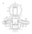
- FIG. 1 is a perspective view illustrating a robot according to an embodiment
- FIG. 2 is a side view of the robot of FIG. 1
- FIG. FIG. 3 is a cross-sectional view along the III-III cutting line in FIG. 2
- It is a figure which illustrates the structure of the vital sensor which concerns on embodiment.
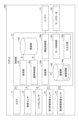
- It is a block diagram which illustrates the hardware constitutions of the control part which concerns on embodiment.
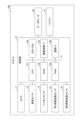
- 4 is a block diagram illustrating the functional configuration of a control unit according to the embodiment
- FIG. 6 is a flowchart illustrating processing of a control unit according to the embodiment
- FIG. 1 is a perspective view illustrating a robot 100 according to an embodiment.
- FIG. 2 is a side view of the robot 100.
- FIG. FIG. 3 is a cross-sectional view taken along line III--III in FIG.
- the robot 100 is a robot that has an exterior member 10 and can be driven by supplied electric power.
- the robot 100 exemplified in this embodiment is a puppet-type robot imitating a bear cub.
- the robot 100 is manufactured with a size and weight suitable for being held by a user.
- the user here means the user of the robot 100 .
- the robot 100 can observe the user's stress state based on the biometric information acquired from the user, relieve the user's stress through communication with the user, and provide comfort to the user.
- communication in this specification includes exchange or communication only in language and exchange or communication involving contact.
- the state in which the user and the robot 100 are communicating includes a state in which the user holds the robot 100 in his/her arms without saying a word and touches the robot 100 while touching the robot 100 .
- the exterior member 10 has flexibility.
- the exterior member 10 has flexibility, for example, by having hardness greater than Asker F0 and less than Asker C70.
- the exterior member 10 includes, for example, a soft material that is comfortable to touch when the user of the robot 100 touches the robot 100 .
- Materials containing organic materials such as urethane foam, rubber, resin, and fiber can be used for the material of the exterior member 10 .
- the exterior member 10 may further include a soft cloth or the like covering the outer surface of the substrate such as foam.
- Foam materials include polystyrene, polyethylene, phenol, rubber-based foam materials, rubber-based sponges, and the like. Cloth includes cloth, brushed material, leather, and the like. Since the foam material is easy to manufacture by molding or the like, the mass productivity of the exterior member 10 can be improved by using the foam material for the exterior member 10 .
- the exterior member 10 may be configured using a cushioning material in which a fluid is wrapped with a resin film such as polyethylene.
- a cushioning material in which a fluid is wrapped with a resin film such as polyethylene.
- the cushioning material include an air cushion in which air is wrapped with a resin film, a material in which liquid or gel is wrapped in a resin film, and the like.
- the robot 100 has, for example, a body 1, a head 2, arms 3, and legs 4.
- the arm portion 3 includes a right arm portion 3a and a left arm portion 3b
- the leg portion 4 includes a right leg portion 4a and a left leg portion 4b.
- the torso 1 corresponds to the main body of the robot.
- Each of the head 2, arms 3 and legs 4 corresponds to a driver connected to the robot body so as to be displaceable relative to the robot body.
- the arm section 3 is configured to be displaceable with respect to the body section 1 .
- the robot 100 displaces the right arm 3a and the left arm 3b and contacts the neck, torso, etc. of the user as if hugging the user. This action makes the user feel a sense of familiarity with the robot 100 , thereby promoting contact between the user and the robot 100 .
- the torso 1, head 2, arms 3 and legs 4 are all covered with exterior members 10.
- the exterior member of the torso 1 and the exterior member of the arms 3 are integrated, and the exterior member of the head 2 is separated from the exterior members of the torso 1 and the arms 3 .
- the leg portion 4 does not include a component such as a sensor inside, and is composed only of an exterior member. However, it is not limited to these configurations, and for example, only parts of the robot 100 that are likely to be touched by the user may be covered with the exterior member 10 .
- At least one of the exterior members 10 in each of the torso 1, the head 2, the arms 3 and the legs 4 may be separated from the other exterior members, or the head 2, the arms 3 and the legs 4 may be separated from each other.
- the non-displaceable portion may be composed only of the exterior member 10 without including a component such as a sensor inside.
- the robot 100 includes a camera 11, a tactile sensor 12, a control unit 13, a vital sensor 14, a battery 15, a first capacitance sensor 21, and a second capacitance sensor 31 inside the exterior member 10. and have
- the robot 100 has a torso frame 16 and a torso mounting table 17 inside the exterior member 10 of the torso 1 .
- the robot 100 also has a head frame 22 and a head mount 23 inside the exterior member 10 of the head 2 .
- the robot 100 has a right arm frame 32a and a right arm mounting base 33 inside the exterior member 10 of the right arm 3a, and has a left arm frame 32b inside the exterior member 10 of the left arm 3b. .
- the torso frame 16, the head frame 22, the right arm frame 32a and the left arm frame 32b are structures each formed by combining a plurality of columnar members.
- the body rest table 17, the head rest table 23, and the right arm rest table 33 are plate-shaped members having mounting surfaces.
- the torso mounting base 17 is fixed to the torso frame 16, the head mounting base 23 is fixed to the head frame 22, and the right arm mounting base 33 is fixed to the right arm frame 32a.
- the torso frame 16, the head frame 22, the right arm frame 32a and the left arm frame 32b may be formed in a box shape including a plurality of plate members.
- the right arm frame 32a is connected to the torso frame 16 via a right arm connecting mechanism 34a, and is driven by a right arm servomotor 35a to be displaceable relative to the torso frame 16. .
- a right arm servomotor 35a By displacing the right arm frame 32a, the right arm 3a is displaced relative to the body 1. As shown in FIG.
- the left arm frame 32b is connected to the torso frame 16 via a left arm connecting mechanism 34b, and is driven by a left arm servomotor 35b so as to be relatively displaceable with respect to the torso frame 16. .
- the left arm 3b is displaced relative to the body 1 by displacing the left arm frame 32b.
- the camera 11 is fixed to the torso frame 16.
- the tactile sensor 12 , the control unit 13 , the vital sensor 14 and the battery 15 are fixed to the body mounting table 17 .
- the control unit 13 and the battery 15 are fixed on the side opposite to the side on which the tactile sensor 12 and the vital sensor 14 are fixed on the body mounting base 17 .
- the arrangement of the control unit 13 and the battery 15 here is not necessarily limited to the above because of the space that can be arranged on the trunk mounting table 17 .
- the battery 15 is fixed on the side opposite to the side on which the tactile sensor 12 and the vital sensor 14 are fixed, the battery 15 is heavier than the other components, so the center of gravity of the robot 100 is lower.
- a low center of gravity of the robot 100 is preferable because at least one of the position and posture of the robot 100 is stable and at least one of charging and replacing the battery 15 is facilitated.
- the first electrostatic capacitance sensor 21 is fixed to the head mounting base 23 and the second electrostatic capacitance sensor 31 is fixed to the right arm mounting base 33 .
- the camera 11, the tactile sensor 12, the control unit 13, the vital sensor 14, the battery 15, the first capacitance sensor 21, the second capacitance sensor 31, etc. can be fixed by screw members, adhesive members, or the like. can.
- a metal material or the like can be used.
- a metal material such as aluminum for the body frame 16, the right arm frame 32a, and the left arm frame 32b.
- a resin material for these parts in order to reduce the weight of the robot 100 if the strength can be ensured.
- the materials of the body rest 17, head frame 22, head rest 23, right arm rest 33, and left arm frame 32b and resin materials or metal materials can be used. From the viewpoint of reducing the weight, it is preferable to use a resin material.
- the control unit 13 communicates with the camera 11, the tactile sensor 12, the vital sensor 14, the first capacitance sensor 21, the second capacitance sensor 31, the right arm servomotor 35a and the left arm servomotor 35b by wire or wirelessly. Connected for communication.
- the camera 11 is an image sensor that outputs captured images around the robot 100 to the control unit 13 .
- the camera 11 is an example of a photographing unit that photographs the user.
- the camera 11 includes a lens and an imaging device that captures an image through the lens.
- a CCD (Charge Coupled Device), a CMOS (Complementary Metal-Oxide Semiconductor), or the like can be used as an imaging device.
- a captured image may be either a still image or a moving image.
- the tactile sensor 12 is a sensor element that detects information sensed by the tactile sense of a human hand or the like, converts it into a tactile signal that is an electric signal, and outputs the tactile signal to the control unit 13 .
- the tactile sensor 12 converts pressure and vibration information generated by the user's contact with the robot 100 into a tactile signal using a piezoelectric element, and outputs the tactile signal to the control unit 13 .
- the vital sensor 14 is an example of an electromagnetic wave sensor that acquires the user's biological information using electromagnetic waves.
- the vital sensor 14 will be described later in detail with reference to FIG.
- the first capacitive sensor 21 and the second capacitive sensor 31 are sensor elements that output to the control unit 13 a capacitive signal that detects the user's contact or proximity to the robot 100 based on a change in the capacitive capacity. is.
- the first capacitance sensor 21 is preferably a rigid sensor that does not have flexibility from the viewpoint of stabilizing the exterior member 10 . Since the arm part 3 is a part that is easily touched by the user, the second capacitance sensor 31 is preferably a sensor having flexibility including conductive thread or the like from the viewpoint of improving the touch feeling.
- the tactile sensor 12 , the first capacitance sensor 21 and the second capacitance sensor 31 all correspond to user detection units that detect the user's contact or proximity to the robot 100 .
- the battery 15 supplies electric power to the camera 11, the tactile sensor 12, the control unit 13, the vital sensor 14, the first capacitance sensor 21, the second capacitance sensor 31, the right arm servomotor 35a, and the left arm servomotor 35b. power supply.
- Various secondary batteries such as a lithium ion battery and a lithium polymer battery can be used as the battery 15 .
- the camera 11, the tactile sensor 12, the first capacitance sensor 21, and the second capacitance sensor 31 in the robot 100 are not essential components, and the robot 100 has at least the vital sensor 14 inside the exterior member 10. It's fine if you have it. These installation positions can also be changed as appropriate.
- the robot 100 does not necessarily have the control unit 13 inside the exterior member 10, and the control unit 13 can also communicate with each device from outside the exterior member 10 via radio.
- the battery 15 can also supply power to each component from the outside of the exterior member 10 .
- the arm section 3 may be an articulated robot arm including a plurality of frame members and a plurality of connecting mechanisms. If the arm 3 is configured by an articulated robot arm, the robot 100 can realize a more realistic hugging motion.
- this embodiment exemplifies a configuration in which only the arms 3 are displaceable, the configuration is not limited to this. good.
- the configuration and shape of the robot 100 are also not limited to those exemplified in the present embodiment, and can be changed as appropriate according to the user's preference, usage pattern of the robot 100, and the like.
- FIG. 4 is a diagram illustrating the configuration of the vital sensor 14. As shown in FIG.
- the vital sensor 14 is a microwave Doppler sensor having a microwave emitter 141 and a microwave receiver 142 . Microwaves are an example of electromagnetic waves.
- the vital sensor 14 emits an emitted wave Ms, which is a microwave, toward the user 200 from the inside of the exterior member 10 of the robot 100 by the microwave emission unit 141, and the emitted wave Ms is a reflected wave reflected by the user 200. Mr is received by the microwave receiver 142 .
- the vital sensor 14 uses the Doppler effect from the difference between the frequency of the emitted wave Ms and the frequency of the reflected wave Mr to detect minute displacements caused on the body surface due to the heartbeat of the user 200 without contact.
- non-contact means that the vital sensor 14 does not touch the body surface of the user 200 or does not keep touching it.
- the vital sensor 14 detects a minute displacement occurring on the body surface of the user 200 through clothes, gloves, or the like worn by the user 200, the above-mentioned non-contact means It means that the vital sensor 14 does not touch, or does not continue to touch, clothes, gloves, or the like.
- the vital sensor 14 can detect minute displacements occurring on the body surface of the user 200 even when the user 200 is in contact with the robot 100 , such as when the user 200 is holding the robot 100 .
- the vital sensor 14 can acquire information such as heartbeat, respiration, pulse wave, blood pressure, etc. as biological information of the user 200 from the detected minute displacements, and output the acquired biological information to the control unit 13 .
- the vital sensor 14 is not limited to a microwave Doppler sensor. It is also possible to use electromagnetic waves other than microwaves, such as microwaves. Also, the vital sensor 14 may be a millimeter wave radar, a microwave radar, or the like.
- electromagnetic waves with a high frequency such as infrared light and visible light
- the transmittance of the exterior member 10 since the transmittance of the exterior member 10 is low, the signal strength of the electromagnetic waves detected by the vital sensor 14 is low, and a minute displacement occurs on the body surface of the user 200. detection accuracy may decrease.
- electromagnetic waves with a low frequency may have a low detection resolution for minute displacements occurring on the body surface of the user 200 .
- the frequency of the electromagnetic waves in the sensor 14 is preferably 30 MHz or more and 100 THz or less. From the above point of view, the frequency of the electromagnetic wave in the vital sensor 14 is more preferably 300 MHz or more and 300 GHz or less, and particularly preferably 1 GHz or more and 100 GHz or less. From the above viewpoint, the thickness of the exterior member 10 is preferably 0.1 mm or more and 1000 mm or less, more preferably 1 mm or more and 500 mm or less, and particularly preferably 5 mm or more and 200 mm or less. . The condition may be a combination of the above condition regarding the frequency of the electromagnetic wave and the above condition regarding the thickness of the exterior member 10 . The thickness of the exterior member 10 in this specification means the thickness when the robot 100 is in use.
- the exterior member 10 may have a transmittance of 1% or more for electromagnetic waves with a frequency of 300 MHz or more and 300 GHz or less. Further, the thickness of the exterior member 10 may be 0.1 mm or more and 1000 mm or less when the transmittance for electromagnetic waves with a frequency of 300 MHz or more and 300 GHz or less is 1% or more.
- the detection accuracy of minute displacements occurring on the body surface of the user 200 can be increased, biometric information signals with a long displacement period can be detected, and the body surface of the user 200 can be detected. It is possible to increase the detection resolution of minute displacements that occur in the
- the biological information detected by the vital sensor 14 may include at least one of pulse, blood pressure, heartbeat, and respiration. More specifically, the biological information detected by the vital sensor 14 includes heartbeat interval, heartbeat variability, LF, HF, LF/HF, pulse wave, pulse, pulse interval RR, pulse wave waveform, pulse wave velocity , hemodynamics, pulse pressure, body temperature, electroencephalogram, blood sugar, respiration, respiration rate, rhythm, respiration depth, and the like. By acquiring and analyzing these biometric information, in the present embodiment, it is possible to acquire information about the mental state or health condition of the user 200 .
- the vital sensor 14 since the vital sensor 14 is provided inside the exterior member 10 , the user 200 cannot visually recognize the vital sensor 14 . As a result, the resistance of the user 200 to the detection of biometric information is suppressed, and the biometric information can be obtained smoothly. In addition, since the vital sensor 14 can acquire biometric information without contact, biometric information can be acquired even if the user moves to some extent, unlike a contact-type sensor that requires the user to be in contact with the same place for a certain period of time.
- the robot 100 can acquire biometric information while being hugged by the user 200 and in contact with or close to the user 200 .
- the robot 100 can acquire highly reliable biological information with suppressed noise.
- FIG. 5 is a block diagram illustrating the hardware configuration of the control unit 13.
- the control unit 13 is constructed by a computer, and includes a CPU (Central Processing Unit) 131, a ROM (Read Only Memory) 132, a RAM (Random Access Memory) 133, and an HDD/SSD (Hard Disk Drive/Solid State Drive). ) 134 , a device connection I/F (Interface) 135 and a communication I/F 136 . These are connected via a system bus A so as to be able to communicate with each other.
- a CPU Central Processing Unit
- ROM Read Only Memory
- RAM Random Access Memory
- HDD/SSD Hard Disk Drive/Solid State Drive
- the CPU 131 executes control processing including various arithmetic processing.
- the ROM 132 stores programs used to drive the CPU 131, such as an IPL (Initial Program Loader).
- a RAM 133 is used as a work area for the CPU 131 .
- the HDD/SSD 134 stores various information such as programs, biological information acquired by the vital sensor 14, information detected by various sensors, and the like.
- the device connection I/F 135 is an interface for connecting the control unit 13 with various external devices.
- the external devices here are the camera 11, the tactile sensor 12, the vital sensor 14, the first capacitance sensor 21, the second capacitance sensor 31, the servo motor 35, the battery 15, and the like.
- the servomotor 35 is a generic term for the right arm servomotor 35a and the left arm servomotor 35b.
- the communication I/F 136 is an interface for communicating with external devices via a communication network or the like.
- the control unit 13 connects to the Internet via the communication I/F 136 and communicates with external devices via the Internet.
- At least part of the functions realized by the CPU 131 may be realized by an electric circuit or an electronic circuit.
- FIG. 6 is a block diagram illustrating the functional configuration of the control unit 13. As shown in FIG. Control unit 13 includes acquisition unit 101, communication control unit 102, storage unit 103, authentication unit 104, registration unit 105, start control unit 106, motor control unit 107, and input/output unit 108. have.
- the control unit 13 can realize each function of the acquisition unit 101 and the input/output unit 108 by the device connection I/F 135 and the like, and can realize the function of the communication control unit 102 by the communication I/F 136 and the like.
- the control unit 13 implements the functions of the storage unit 103 and the registration unit 105 using the HDD/SSD 134 or the like, and the CPU 131 stores the functions of the authentication unit 104, the start control unit 106, and the motor control unit 107 in the ROM 132 or the like. It can be realized by executing the processing specified in the specified program.
- Some of the above functions of the control unit 13 may be implemented by an external device such as a PC (Personal Computer), or may be implemented by distributed processing between the control unit 13 and the external device.
- the acquisition unit 101 acquires the biological information B from the vital sensor 14 by controlling communication between the control unit 13 and the vital sensor 14 .
- the communication control unit 102 controls communication with external devices via a communication network or the like.
- the communication control unit 102 can transmit the biological information B acquired by the vital sensor 14 to an external device via a communication network.
- the storage unit 103 stores the biological information B acquired by the vital sensor 14 .
- the storage unit 103 continuously stores the acquired biometric information B while the acquisition unit 101 is acquiring the biometric information B from the vital sensor 14 .
- the storage unit 103 also stores an image Im captured by the camera 11, a tactile signal S from the tactile sensor 12, a first capacitance signal C1 from the first capacitance sensor 21, and a second capacitance signal C1 from the second capacitance sensor 31. 2 Information and the like obtained based on the capacitance signal C2 and the like can also be stored.
- the authentication unit 104 authenticates the user 200 based on the image Im of the user 200 captured by the camera 11 .
- the authentication unit 104 performs face authentication by referring to registration information 109 of a face image registered in advance in the registration unit 105 based on a photographed image Im including the face of the user 200 photographed by the camera 11 .
- the user 200 who is currently in contact with or close to the robot 100 is associated with the pre-registered personal information, and the biometric information B acquired by the vital sensor 14 is associated with the personal information.
- the control unit 13 can also perform control so as to stop the acquisition of biometric information by the vital sensor 14 when the face image included in the captured image Im is not registered in the registration unit 105 .
- the start control unit 106 causes the vital sensor 14 to start acquiring the biological information B based on at least one of the tactile signal S, the first capacitance signal C1, and the second capacitance signal C2 as the detection result. For example, when the contact or proximity of the user 200 to the robot 100 is detected based on the above detection result, the start control unit 106 turns on a switch or the like that supplies power from the battery 15 to the vital sensor 14, thereby turning on the vital sensor. 14 to start acquiring the biometric information B.
- the motor control unit 107 controls driving of the servo motor 35 .
- the input/output unit 108 controls communication between the control unit 13 and external devices.
- the input/output unit 108 can input the captured image Im, the tactile signal S, the first capacitance signal C1, the second capacitance signal C2, and the like, and output information or signals to an external device. can.
- FIG. 7 is a flowchart illustrating processing of the control unit 13 .
- FIG. 7 shows a process of obtaining biological information from the vital sensor 14 by the control unit 13 . 7 when user 200 touches or approaches robot 100 based on at least one of tactile signal S, first capacitance signal C1, and second capacitance signal C2. Start processing. At the time of this start, power is supplied from the battery 15 to the camera 11, the tactile sensor 12, the first capacitance sensor 21, the second capacitance sensor 31, and the servo motor 35, and the vital sensor 14 shall not be supplied with power.
- step S71 the control unit 13 causes the vital sensor 14 to start acquiring the biological information B by turning on a switch or the like that supplies power from the battery 15 to the vital sensor 14 by the start control unit 106 .
- step S ⁇ b>72 the control unit 13 causes the acquisition unit 101 to acquire the biological information B from the vital sensor 14 and store it in the storage unit 103 .
- step S73 the control unit 13 determines whether or not to end acquisition of biometric information. For example, based on at least one of the haptic signal S, the first capacitance signal C1, and the second capacitance signal C2, the control unit 13, when the user 200 touches or approaches the robot 100 is no longer detected, It is determined to end acquisition of biometric information. Alternatively, the control unit 13 may determine to end acquisition of the biometric information when the continuous acquisition amount or the continuous acquisition time of the biometric information B exceeds a predetermined threshold value.
- step S73 when it is determined to end (step S73, Yes), the control unit 13 ends the processing, and when it is determined not to end (step S73, No), the control unit 13 performs the processing after step S72. process again.
- the control unit 13 can perform the biometric information B acquisition process.
- the vital sensor 14 may be in a standby state (sleep state) such as a state in which the power supply amount is suppressed. That is, the control unit 13 may cause the vital sensor 14 to start acquiring the biometric information B by returning from the standby state in which the power supply is suppressed to a state in which the biometric information B can be acquired.
- the robot 100 has the exterior member 10 and the vital sensor 14 (electromagnetic wave sensor) that acquires the biological information B of the user 200 using microwaves (electromagnetic waves).
- the vital sensor 14 is provided inside the exterior member 10 .
- the vital sensor 14 becomes invisible to the user 200 .
- the vital sensor 14 can obtain the biological information B in a non-contact manner using microwaves.
- the vital sensor 14 can acquire biometric information B even if the user moves to some extent, unlike a contact sensor that requires the user to be in contact with the same place for a certain period of time. As a result, the resistance of the user 200 to the acquisition of his/her own biometric information can be suppressed, so that the robot 100 capable of naturally acquiring the biometric information B can be provided.
- the exterior member 10 is configured to contain an organic material. Since the organic material transmits microwaves, the biological information B can be acquired by the vital sensor 14 provided inside the exterior member 10 .
- the exterior member 10 has flexibility.
- the exterior member 10 may have a flexible portion that is a portion having a hardness greater than Asker F0 and less than Asker C70.
- the user 200 can easily touch the robot 100 because the exterior member 10 has flexibility or a flexible portion. Accordingly, in the present embodiment, contact between the user 200 and the robot 100 can be promoted.
- the exterior member 10 may have a flexible portion outside the vital sensor 14 .
- the exterior member 10 has a flexible portion between the vital sensor 14 arranged inside the exterior member 10 and the user 200 in contact with the robot 100 . Since the exterior member 10 has the flexible portion outside the vital sensor 14 , the user 200 in contact with the robot 100 can feel the softness of the flexible portion without feeling the hardness of the vital sensor 14 . This makes it easier for the user 200 to touch the robot 100, so that contact between the user 200 and the robot 100 can be promoted.
- the robot body may include a flexible portion. Since the robot main body includes the flexible portion, the user 200 can easily touch the robot 100 . Accordingly, in the present embodiment, contact between the user 200 and the robot 100 can be promoted.
- the robot main body has at least the trunk portion 1, and the trunk portion 1 may include a flexible portion.
- the torso 1 includes the abdomen, chest, back, waist, buttocks, and the like of the robot 100 . Since the torso 1 is a portion of the robot 100 that is frequently touched by the user 200 , since the torso 1 includes the flexible portion, the user 200 who comes into contact with the robot 100 is more likely to feel the softness. Since this makes it easier for the user 200 to touch the robot 100 , in this embodiment, contact between the user 200 and the robot 100 can be promoted.
- the torso 1 has at least an abdomen, and the abdomen may include a flexible portion.
- the abdomen is a part that the user 200 comes into contact with particularly frequently. Since this makes it easier for the user 200 to touch the robot 100 , in this embodiment, contact between the user 200 and the robot 100 can be promoted.
- the robot 100 has a torso 1 (robot main body) and an arm 3 (driving body) connected to the torso 1 so as to be relatively displaceable.
- the robot 100 makes contact with the user 200 via the arm 3 and can perform, for example, an hugging action in which the arm 3 is brought into contact with the user's 200 neck, torso, or the like. These can give the user 200 a sense of familiarity with the robot 100 , thereby promoting interaction between the user 200 and the robot 100 .
- the robot 100 has a camera 11 (capturing unit) that captures the user 200 and an authentication unit 104 that personally authenticates the user 200 based on the image Im captured by the camera 11 .
- the robot 100 can acquire the biometric information B associated with the personal information by using the authentication result from the authentication unit 104 .
- the robot 100 has a tactile sensor 12 that detects contact or proximity of the user 200 to the robot 100, a first capacitance sensor 21, and a second capacitance sensor 31 (user detection unit).
- the robot 100 also has a start control unit that causes the vital sensor 14 to start acquiring the biological information B based on at least one of the tactile signal S, the first capacitance signal C1, and the second capacitance signal C2 (detection result). 106.
- the robot 100 can reduce power consumption required for acquiring the biometric information B.
- the robot according to the embodiment is particularly suitable for use in supporting a user's safe, secure, or healthy life, but is not limited to this use, and can be used for various uses for acquiring biometric information of a user. ,
- a robot comprising an exterior member and an electromagnetic wave sensor provided inside the exterior member for obtaining biological information of a user using electromagnetic waves.
- the exterior member has the flexible portion outside the electromagnetic wave sensor.
- ⁇ 6> The robot body according to ⁇ 4> or ⁇ 5>, wherein the robot main body includes the flexible portion.
- the robot main body includes the flexible portion.
- the robot main body has at least a trunk portion, and the trunk portion includes the flexible portion.
- the body has at least an abdomen, and the abdomen includes the flexible portion.
- the exterior member has a transmittance of 1% or more for electromagnetic waves having a frequency of 300 MHz or more and 300 GHz or less.
- the exterior member has a thickness of 0.1 mm or more and 1000 mm or less.
- ⁇ 11> The robot according to any one of ⁇ 1> to ⁇ 10>, including a robot main body and a driving body connected to the robot main body so as to be relatively displaceable.
- ⁇ 12> The robot according to ⁇ 11>, wherein the driver includes an arm that is displaceable relative to the robot main body.
- ⁇ 14> The ⁇ 1> to the robot according to any one of ⁇ 12>.
Landscapes
- Engineering & Computer Science (AREA)
- Health & Medical Sciences (AREA)
- Life Sciences & Earth Sciences (AREA)
- Mechanical Engineering (AREA)
- Robotics (AREA)
- Physics & Mathematics (AREA)
- Medical Informatics (AREA)
- Public Health (AREA)
- Biomedical Technology (AREA)
- Heart & Thoracic Surgery (AREA)
- Biophysics (AREA)
- Molecular Biology (AREA)
- Surgery (AREA)
- Animal Behavior & Ethology (AREA)
- General Health & Medical Sciences (AREA)
- Pathology (AREA)
- Veterinary Medicine (AREA)
- Human Computer Interaction (AREA)
- Radiology & Medical Imaging (AREA)
- Nuclear Medicine, Radiotherapy & Molecular Imaging (AREA)
- Multimedia (AREA)
- Electromagnetism (AREA)
- Manipulator (AREA)
Abstract
Description
図1から図3を参照して、実施形態に係るロボット100の構成について説明する。図1は、実施形態に係るロボット100を例示する斜視図である。図2は、ロボット100の側面図である。図3は、図2におけるIII-III切断線に沿う断面図である。
図4は、バイタルセンサ14の構成を例示する図である。バイタルセンサ14は、マイクロ波発射部141と、マイクロ波受信部142と、有するマイクロ波ドップラーセンサである。マイクロ波は電磁波の一例である。
(ハードウェア構成例)
図5は、制御部13のハードウェア構成を例示するブロック図である。制御部13は、コンピュータによって構築されており、CPU(Central Processing Unit)131と、ROM(Read Only Memory)132と、RAM(Random Access Memory)133と、HDD/SSD(Hard Disk Drive/Solid State Drive)134と、機器接続I/F(Interface)135と、通信I/F136と、を有する。これらは、システムバスAを介して相互に通信可能に接続している。
図6は、制御部13の機能構成を例示するブロック図である。制御部13は、取得部101と、通信制御部102と、格納部103と、認証部104と、登録部105と、開始制御部106と、モータ制御部107と、入出力部108と、を有する。
図7は、制御部13の処理を例示するフローチャートである。図7は、制御部13により、バイタルセンサ14に生体情報を取得する処理を示している。制御部13は、触覚信号S、第1静電容量信号C1および第2静電容量信号C2の少なくとも1つに基づき、ロボット100に対するユーザ200の接触または近接が検出された場合に、図7の処理を開始する。なお、この開始時においては、カメラ11、触覚センサ12、第1静電容量センサ21、第2静電容量センサ31およびサーボモータ35には、バッテリ15から電力が供給されており、バイタルセンサ14には電力が供給されていないものとする。
以上説明したように、ロボット100は、外装部材10と、マイクロ波(電磁波)を利用してユーザ200の生体情報Bを取得するバイタルセンサ14(電磁波センサ)と、を有する。バイタルセンサ14は、外装部材10の内側に設けられている。外装部材10の内側にバイタルセンサ14を設けることにより、バイタルセンサ14は、ユーザ200が視認できない状態になる。またバイタルセンサ14は、マイクロ波を利用して非接触で生体情報Bを取得できる。さらにバイタルセンサ14は、ユーザが同じ場所に一定期間接触することが求められる接触センサとは異なり、ユーザがある程度動いたとしても生体情報Bを取得できる。これらにより、自身の生体情報が取得されることに対するユーザ200の抵抗感を抑制できるため、生体情報Bを自然に取得可能なロボット100を提供できる。
<1> 外装部材と、前記外装部材の内側に設けられ、電磁波を利用してユーザの生体情報を取得する電磁波センサと、を有する、ロボットである。
<2> 前記外装部材は、有機材料を含んで構成されている、前記<1>に記載のロボットである。
<3> 前記外装部材は、柔軟性を有する、前記<1>または前記<2>に記載のロボットである。
<4> 前記外装部材は、硬度がアスカーF0よりも大きく、かつアスカーC70以下の部分である柔軟部を有する、前記<3>に記載のロボットである。
<5> 前記外装部材は、前記電磁波センサの外側に前記柔軟部を有する、前記<4>に記載のロボットである。
<6> ロボット本体は、前記柔軟部を含む、前記<4>または前記<5>に記載のロボットである。
<7> 前記ロボット本体は、少なくとも胴部を有し、前記胴部は、前記柔軟部を含む、前記<6>に記載のロボットである。
<8> 前記胴部は、少なくとも腹部を有し、前記腹部は、前記柔軟部を含む、前記<7>に記載のロボットである。
<9> 前記外装部材は、周波数が300MHz以上300GHz以下の電磁波に対する透過率が1%以上である、前記<1>から前記<8>のいずれか1つに記載のロボットである。
<10> 前記外装部材の厚みは、0.1mm以上1000mm以下である、前記<9>に記載のロボットである。
<11> ロボット本体と、前記ロボット本体に対して相対的に変位可能に連結される駆動体と、を有する、前記<1>から前記<10>のいずれか1つに記載のロボットである。
<12> 前記駆動体は、前記ロボット本体と相対的に変位可能な腕部を含む、前記<11>に記載のロボットである。
<13> 前記ユーザを撮影する撮影部と、前記撮影部による撮影画像に基づいて前記ユーザを個人認証する認証部と、を有する、前記<1>から前記<12>のいずれか1つに記載のロボットである。
<14> 前記ロボットに対する前記ユーザの接触または近接を検出するユーザ検出部と、 前記ユーザ検出部による検出結果に基づき、前記電磁波センサに生体情報の取得を開始させる制御部と、を有する、前記<1>から前記<12>のいずれか1つに記載のロボットである。
2 頭部
3 腕部
3a 右腕部
3b 左腕部
4 脚部
4a 右脚部
4b 左脚部
10 外装部材
11 カメラ
12 触覚センサ
13 制御部
14 バイタルセンサ(電磁波センサ)
141 マイクロ波発射部
142 マイクロ波受信部
15 バッテリ
16 胴部フレーム
17 胴部載置台
21 第1静電容量センサ
22 頭部フレーム
23 頭部載置台
31 第2静電容量センサ
32a 右腕部フレーム
32b 左腕部フレーム
33 右腕部載置台
34a 右腕部連結機構
34b 左腕部連結機構
35 サーボモータ
35a 右腕部サーボモータ
35b 左腕部サーボモータ
100 ロボット
101 取得部
102 通信制御部
103 格納部
104 認証部
105 登録部
106 開始制御部
107 モータ制御部
108 入出力部
109 登録情報
131 CPU
132 ROM
133 RAM
134 HDD/SSD
135 機器接続I/F
136 通信I/F
200 ユーザ
A システムバス
B 生体情報
C1 第1静電容量信号
C2 第2静電容量信号
Im 撮影画像
Ms 発射波
Mr 反射波
Claims (14)
- 外装部材と、
前記外装部材の内側に設けられ、電磁波を利用してユーザの生体情報を取得する電磁波センサと、を有する、ロボット。 - 前記外装部材は、有機材料を含んで構成されている、請求項1に記載のロボット。
- 前記外装部材は、柔軟性を有する、請求項1に記載のロボット。
- 前記外装部材は、硬度がアスカーF0よりも大きく、かつアスカーC70以下の部分である柔軟部を有する、請求項3に記載のロボット。
- 前記外装部材は、前記電磁波センサの外側に前記柔軟部を有する、請求項4に記載のロボット。
- ロボット本体は、前記柔軟部を含む、請求項4に記載のロボット。
- 前記ロボット本体は、少なくとも胴部を有し、
前記胴部は、前記柔軟部を含む、請求項6に記載のロボット。 - 前記胴部は、少なくとも腹部を有し、
前記腹部は、前記柔軟部を含む、請求項7に記載のロボット。 - 前記外装部材は、周波数が300MHz以上300GHz以下の電磁波に対する透過率が1%以上である、請求項3に記載のロボット。
- 前記外装部材の厚みは、0.1mm以上1000mm以下である、請求項9に記載のロボット。
- ロボット本体と、
前記ロボット本体に対して相対的に変位可能に連結される駆動体と、を有する、請求項3に記載のロボット。 - 前記駆動体は、前記ロボット本体と相対的に変位可能な腕部を含む、請求項11に記載のロボット。
- 前記ユーザを撮影する撮影部と、
前記撮影部による撮影画像に基づいて前記ユーザを個人認証する認証部と、を有する、請求項1から請求項12のいずれか1項に記載のロボット。 - 前記ロボットに対する前記ユーザの接触または近接を検出するユーザ検出部と、
前記ユーザ検出部による検出結果に基づき、前記電磁波センサに生体情報の取得を開始させる制御部と、を有する、請求項1から請求項12のいずれか1項に記載のロボット。
Priority Applications (5)
| Application Number | Priority Date | Filing Date | Title |
|---|---|---|---|
| US18/834,828 US20250107755A1 (en) | 2022-02-02 | 2023-01-25 | Robot |
| EP23749630.2A EP4474031A4 (en) | 2022-02-02 | 2023-01-25 | ROBOT |
| CN202380019526.1A CN118632733A (zh) | 2022-02-02 | 2023-01-25 | 机器人 |
| KR1020247028820A KR20240144269A (ko) | 2022-02-02 | 2023-01-25 | 로봇 |
| JP2023578507A JPWO2023149314A1 (ja) | 2022-02-02 | 2023-01-25 |
Applications Claiming Priority (2)
| Application Number | Priority Date | Filing Date | Title |
|---|---|---|---|
| JP2022014594 | 2022-02-02 | ||
| JP2022-014594 | 2022-02-02 |
Publications (1)
| Publication Number | Publication Date |
|---|---|
| WO2023149314A1 true WO2023149314A1 (ja) | 2023-08-10 |
Family
ID=87552252
Family Applications (1)
| Application Number | Title | Priority Date | Filing Date |
|---|---|---|---|
| PCT/JP2023/002331 Ceased WO2023149314A1 (ja) | 2022-02-02 | 2023-01-25 | ロボット |
Country Status (7)
| Country | Link |
|---|---|
| US (1) | US20250107755A1 (ja) |
| EP (1) | EP4474031A4 (ja) |
| JP (1) | JPWO2023149314A1 (ja) |
| KR (1) | KR20240144269A (ja) |
| CN (1) | CN118632733A (ja) |
| TW (1) | TW202335628A (ja) |
| WO (1) | WO2023149314A1 (ja) |
Cited By (1)
| Publication number | Priority date | Publication date | Assignee | Title |
|---|---|---|---|---|
| WO2024204484A1 (ja) * | 2023-03-29 | 2024-10-03 | 日東電工株式会社 | ロボット |
Families Citing this family (1)
| Publication number | Priority date | Publication date | Assignee | Title |
|---|---|---|---|---|
| WO2022259595A1 (ja) * | 2021-06-10 | 2022-12-15 | ソニーグループ株式会社 | 介護ロボット |
Citations (5)
| Publication number | Priority date | Publication date | Assignee | Title |
|---|---|---|---|---|
| JP2011115936A (ja) * | 2009-11-04 | 2011-06-16 | Advanced Telecommunication Research Institute International | 触覚提示付ロボット |
| JP6519560B2 (ja) | 2016-09-23 | 2019-05-29 | カシオ計算機株式会社 | ロボット、ロボットの作動方法及びプログラム |
| WO2019220899A1 (ja) * | 2018-05-16 | 2019-11-21 | 富士フイルム株式会社 | 生体情報取得システム、電子機器、生体情報取得方法、及び生体情報取得プログラム |
| JP2020192076A (ja) * | 2019-05-28 | 2020-12-03 | 国立大学法人 東京大学 | 健康状態評価システムおよびこれに用いられる健康情報取得装置、健康情報取得方法並びに曲げ認識センサ |
| JP2022014594A (ja) | 2020-07-07 | 2022-01-20 | 東芝三菱電機産業システム株式会社 | 電力変換装置、半導体スイッチ装置及び製造方法 |
Family Cites Families (8)
| Publication number | Priority date | Publication date | Assignee | Title |
|---|---|---|---|---|
| JP2004337556A (ja) * | 2003-05-13 | 2004-12-02 | Yasuo Fujii | 生体情報取得手段を具備し健康管理機能を備えたロボット |
| JP4620959B2 (ja) * | 2004-03-26 | 2011-01-26 | キヤノン株式会社 | 生体情報モニタ装置 |
| US20130141306A1 (en) * | 2011-12-01 | 2013-06-06 | Chiu-Lin Chiang | Mixed antenna system driving method |
| JPWO2018074576A1 (ja) * | 2016-10-21 | 2019-08-29 | Wvs株式会社 | 生体情報監視装置及びシステム |
| JP6517457B2 (ja) * | 2017-04-10 | 2019-05-22 | Groove X株式会社 | 外皮を装着するロボット |
| CA3030904A1 (en) * | 2018-01-22 | 2019-07-22 | Fiona E. Kalensky | System and method for a digitally-interactive plush body therapeutic apparatus |
| JP7107017B2 (ja) * | 2018-06-21 | 2022-07-27 | カシオ計算機株式会社 | ロボット、ロボットの制御方法及びプログラム |
| JP7298861B2 (ja) * | 2018-08-31 | 2023-06-27 | Groove X株式会社 | 日常生活を記録する自律行動型ロボット |
-
2023
- 2023-01-25 KR KR1020247028820A patent/KR20240144269A/ko active Pending
- 2023-01-25 JP JP2023578507A patent/JPWO2023149314A1/ja active Pending
- 2023-01-25 CN CN202380019526.1A patent/CN118632733A/zh active Pending
- 2023-01-25 EP EP23749630.2A patent/EP4474031A4/en active Pending
- 2023-01-25 WO PCT/JP2023/002331 patent/WO2023149314A1/ja not_active Ceased
- 2023-01-25 US US18/834,828 patent/US20250107755A1/en active Pending
- 2023-01-30 TW TW112103061A patent/TW202335628A/zh unknown
Patent Citations (5)
| Publication number | Priority date | Publication date | Assignee | Title |
|---|---|---|---|---|
| JP2011115936A (ja) * | 2009-11-04 | 2011-06-16 | Advanced Telecommunication Research Institute International | 触覚提示付ロボット |
| JP6519560B2 (ja) | 2016-09-23 | 2019-05-29 | カシオ計算機株式会社 | ロボット、ロボットの作動方法及びプログラム |
| WO2019220899A1 (ja) * | 2018-05-16 | 2019-11-21 | 富士フイルム株式会社 | 生体情報取得システム、電子機器、生体情報取得方法、及び生体情報取得プログラム |
| JP2020192076A (ja) * | 2019-05-28 | 2020-12-03 | 国立大学法人 東京大学 | 健康状態評価システムおよびこれに用いられる健康情報取得装置、健康情報取得方法並びに曲げ認識センサ |
| JP2022014594A (ja) | 2020-07-07 | 2022-01-20 | 東芝三菱電機産業システム株式会社 | 電力変換装置、半導体スイッチ装置及び製造方法 |
Non-Patent Citations (1)
| Title |
|---|
| See also references of EP4474031A4 |
Cited By (1)
| Publication number | Priority date | Publication date | Assignee | Title |
|---|---|---|---|---|
| WO2024204484A1 (ja) * | 2023-03-29 | 2024-10-03 | 日東電工株式会社 | ロボット |
Also Published As
| Publication number | Publication date |
|---|---|
| EP4474031A1 (en) | 2024-12-11 |
| US20250107755A1 (en) | 2025-04-03 |
| CN118632733A (zh) | 2024-09-10 |
| EP4474031A4 (en) | 2025-10-15 |
| KR20240144269A (ko) | 2024-10-02 |
| TW202335628A (zh) | 2023-09-16 |
| JPWO2023149314A1 (ja) | 2023-08-10 |
Similar Documents
| Publication | Publication Date | Title |
|---|---|---|
| WO2023149314A1 (ja) | ロボット | |
| CN102551685B (zh) | 对象监视器 | |
| CN107870589B (zh) | 机器人、机器人的控制方法以及记录介质 | |
| EP1447653A1 (en) | PRESSURE−SENSITIVE SENSOR AND MONITOR USING THE PRESSURE−SENSITIVE SENSOR | |
| JP2014502203A (ja) | 睡眠姿勢検知及び監視システム | |
| US11419549B2 (en) | Sticking-type device for living body | |
| CN116018080A (zh) | 步态调节辅助系统 | |
| US12436047B2 (en) | Stretchable fiber optic pressure sensors and uses thereof | |
| US20260102916A1 (en) | Robot | |
| CN107491191B (zh) | 具有降温除汗功能的鼠标系统 | |
| WO2017181744A1 (zh) | 用于保持人体健康姿势的背部装置 | |
| US20260102925A1 (en) | Robot | |
| Chen et al. | Personalized biomedical devices & systems for healthcare applications | |
| US20260109036A1 (en) | Robot, control method, and program | |
| US20250147064A1 (en) | Sensor device and sensor assembly | |
| JP2025172991A (ja) | ロボット | |
| CN109513091B (zh) | 助眠设备及系统 | |
| WO2024071170A1 (ja) | ヒータモジュール、およびロボット | |
| JP3209378U (ja) | 弾性デバイス | |
| US20250303312A1 (en) | Interaction apparatus | |
| CN206434309U (zh) | 弹性装置 | |
| US20150238145A1 (en) | Mouse device | |
| WO2025028370A1 (ja) | ロボット、ロボットの制御方法、及びプログラム |
Legal Events
| Date | Code | Title | Description |
|---|---|---|---|
| 121 | Ep: the epo has been informed by wipo that ep was designated in this application |
Ref document number: 23749630 Country of ref document: EP Kind code of ref document: A1 |
|
| WWE | Wipo information: entry into national phase |
Ref document number: 202380019526.1 Country of ref document: CN |
|
| WWE | Wipo information: entry into national phase |
Ref document number: 18834828 Country of ref document: US |
|
| ENP | Entry into the national phase |
Ref document number: 2023578507 Country of ref document: JP Kind code of ref document: A |
|
| ENP | Entry into the national phase |
Ref document number: 20247028820 Country of ref document: KR Kind code of ref document: A |
|
| WWE | Wipo information: entry into national phase |
Ref document number: 2023749630 Country of ref document: EP |
|
| NENP | Non-entry into the national phase |
Ref country code: DE |
|
| ENP | Entry into the national phase |
Ref document number: 2023749630 Country of ref document: EP Effective date: 20240902 |
|
| WWP | Wipo information: published in national office |
Ref document number: 18834828 Country of ref document: US |