WO2023149356A1 - 遠位スタビライザ及び遠位スタビライザの撮像方法 - Google Patents
遠位スタビライザ及び遠位スタビライザの撮像方法 Download PDFInfo
- Publication number
- WO2023149356A1 WO2023149356A1 PCT/JP2023/002524 JP2023002524W WO2023149356A1 WO 2023149356 A1 WO2023149356 A1 WO 2023149356A1 JP 2023002524 W JP2023002524 W JP 2023002524W WO 2023149356 A1 WO2023149356 A1 WO 2023149356A1
- Authority
- WO
- WIPO (PCT)
- Prior art keywords
- distal
- catheter
- visibility
- delivery wire
- biological lumen
- Prior art date
- Legal status (The legal status is an assumption and is not a legal conclusion. Google has not performed a legal analysis and makes no representation as to the accuracy of the status listed.)
- Ceased
Links
Images



Classifications
-
- A—HUMAN NECESSITIES
- A61—MEDICAL OR VETERINARY SCIENCE; HYGIENE
- A61M—DEVICES FOR INTRODUCING MEDIA INTO, OR ONTO, THE BODY; DEVICES FOR TRANSDUCING BODY MEDIA OR FOR TAKING MEDIA FROM THE BODY; DEVICES FOR PRODUCING OR ENDING SLEEP OR STUPOR
- A61M25/00—Catheters; Hollow probes
- A61M25/01—Introducing, guiding, advancing, emplacing or holding catheters
- A61M25/02—Holding devices, e.g. on the body
- A61M25/04—Holding devices, e.g. on the body in the body, e.g. expansible
-
- A—HUMAN NECESSITIES
- A61—MEDICAL OR VETERINARY SCIENCE; HYGIENE
- A61M—DEVICES FOR INTRODUCING MEDIA INTO, OR ONTO, THE BODY; DEVICES FOR TRANSDUCING BODY MEDIA OR FOR TAKING MEDIA FROM THE BODY; DEVICES FOR PRODUCING OR ENDING SLEEP OR STUPOR
- A61M25/00—Catheters; Hollow probes
- A61M25/01—Introducing, guiding, advancing, emplacing or holding catheters
- A61M25/06—Body-piercing guide needles or the like
- A61M25/0662—Guide tubes
-
- A—HUMAN NECESSITIES
- A61—MEDICAL OR VETERINARY SCIENCE; HYGIENE
- A61B—DIAGNOSIS; SURGERY; IDENTIFICATION
- A61B17/00—Surgical instruments, devices or methods
- A61B17/12—Surgical instruments, devices or methods for ligaturing or otherwise compressing tubular parts of the body, e.g. blood vessels or umbilical cord
- A61B17/12022—Occluding by internal devices, e.g. balloons or releasable wires
- A61B17/12099—Occluding by internal devices, e.g. balloons or releasable wires characterised by the location of the occluder
- A61B17/12109—Occluding by internal devices, e.g. balloons or releasable wires characterised by the location of the occluder in a blood vessel
- A61B17/12113—Occluding by internal devices, e.g. balloons or releasable wires characterised by the location of the occluder in a blood vessel within an aneurysm
- A61B17/12118—Occluding by internal devices, e.g. balloons or releasable wires characterised by the location of the occluder in a blood vessel within an aneurysm for positioning in conjunction with a stent
-
- A—HUMAN NECESSITIES
- A61—MEDICAL OR VETERINARY SCIENCE; HYGIENE
- A61M—DEVICES FOR INTRODUCING MEDIA INTO, OR ONTO, THE BODY; DEVICES FOR TRANSDUCING BODY MEDIA OR FOR TAKING MEDIA FROM THE BODY; DEVICES FOR PRODUCING OR ENDING SLEEP OR STUPOR
- A61M25/00—Catheters; Hollow probes
- A61M25/01—Introducing, guiding, advancing, emplacing or holding catheters
- A61M25/0105—Steering means as part of the catheter or advancing means; Markers for positioning
- A61M25/0108—Steering means as part of the catheter or advancing means; Markers for positioning using radio-opaque or ultrasound markers
-
- A—HUMAN NECESSITIES
- A61—MEDICAL OR VETERINARY SCIENCE; HYGIENE
- A61M—DEVICES FOR INTRODUCING MEDIA INTO, OR ONTO, THE BODY; DEVICES FOR TRANSDUCING BODY MEDIA OR FOR TAKING MEDIA FROM THE BODY; DEVICES FOR PRODUCING OR ENDING SLEEP OR STUPOR
- A61M25/00—Catheters; Hollow probes
- A61M25/01—Introducing, guiding, advancing, emplacing or holding catheters
- A61M25/02—Holding devices, e.g. on the body
-
- A—HUMAN NECESSITIES
- A61—MEDICAL OR VETERINARY SCIENCE; HYGIENE
- A61M—DEVICES FOR INTRODUCING MEDIA INTO, OR ONTO, THE BODY; DEVICES FOR TRANSDUCING BODY MEDIA OR FOR TAKING MEDIA FROM THE BODY; DEVICES FOR PRODUCING OR ENDING SLEEP OR STUPOR
- A61M25/00—Catheters; Hollow probes
- A61M2025/0004—Catheters; Hollow probes having two or more concentrically arranged tubes for forming a concentric catheter system
- A61M2025/0006—Catheters; Hollow probes having two or more concentrically arranged tubes for forming a concentric catheter system which can be secured against axial movement, e.g. by using a locking cuff
-
- A—HUMAN NECESSITIES
- A61—MEDICAL OR VETERINARY SCIENCE; HYGIENE
- A61M—DEVICES FOR INTRODUCING MEDIA INTO, OR ONTO, THE BODY; DEVICES FOR TRANSDUCING BODY MEDIA OR FOR TAKING MEDIA FROM THE BODY; DEVICES FOR PRODUCING OR ENDING SLEEP OR STUPOR
- A61M25/00—Catheters; Hollow probes
- A61M2025/0008—Catheters; Hollow probes having visible markings on its surface, i.e. visible to the naked eye, for any purpose, e.g. insertion depth markers, rotational markers or identification of type
-
- A—HUMAN NECESSITIES
- A61—MEDICAL OR VETERINARY SCIENCE; HYGIENE
- A61M—DEVICES FOR INTRODUCING MEDIA INTO, OR ONTO, THE BODY; DEVICES FOR TRANSDUCING BODY MEDIA OR FOR TAKING MEDIA FROM THE BODY; DEVICES FOR PRODUCING OR ENDING SLEEP OR STUPOR
- A61M25/00—Catheters; Hollow probes
- A61M25/01—Introducing, guiding, advancing, emplacing or holding catheters
- A61M25/06—Body-piercing guide needles or the like
- A61M25/0662—Guide tubes
- A61M2025/0681—Systems with catheter and outer tubing, e.g. sheath, sleeve or guide tube
-
- A—HUMAN NECESSITIES
- A61—MEDICAL OR VETERINARY SCIENCE; HYGIENE
- A61M—DEVICES FOR INTRODUCING MEDIA INTO, OR ONTO, THE BODY; DEVICES FOR TRANSDUCING BODY MEDIA OR FOR TAKING MEDIA FROM THE BODY; DEVICES FOR PRODUCING OR ENDING SLEEP OR STUPOR
- A61M2205/00—General characteristics of the apparatus
- A61M2205/02—General characteristics of the apparatus characterised by a particular materials
- A61M2205/0216—Materials providing elastic properties, e.g. for facilitating deformation and avoid breaking
-
- A—HUMAN NECESSITIES
- A61—MEDICAL OR VETERINARY SCIENCE; HYGIENE
- A61M—DEVICES FOR INTRODUCING MEDIA INTO, OR ONTO, THE BODY; DEVICES FOR TRANSDUCING BODY MEDIA OR FOR TAKING MEDIA FROM THE BODY; DEVICES FOR PRODUCING OR ENDING SLEEP OR STUPOR
- A61M2205/00—General characteristics of the apparatus
- A61M2205/58—Means for facilitating use, e.g. by people with impaired vision
- A61M2205/583—Means for facilitating use, e.g. by people with impaired vision by visual feedback
Definitions
- the present invention relates to a distal stabilizer used for catheter delivery in a biological lumen and an imaging method for the distal stabilizer.
- Patent Literature 1 discloses a distal stabilizer (anchor device) in which an anchoring stent is joined to the distal end of a delivery wire. When the stent is released from the microcatheter and expanded, the stent is anchored to the inner wall of the blood vessel. Therefore, it is possible to easily perform the operation of delivering the target catheter extrapolated to the microcatheter to the vicinity of the target position.
- Various treatments using treatment devices are performed on lesions within the body lumen.
- the target catheter, one or more microcatheters thinner than the target catheter, and a delivery wire inserted into the microcatheter are used.
- a delivery wire is advanced distally, a microcatheter attached to the delivery wire is guided to the vicinity of the target location, and then the target catheter attached to the microcatheter is guided to the vicinity of the target location. It is a procedure of induction.
- the target catheter When an aneurysm exists in a blood vessel, which is a biological lumen, if a delivery wire or microcatheter strays into this aneurysm, the target catheter, which has a larger inner diameter than the microcatheter, loses its ability to advance in the intended direction. Decreased delivery performance. In particular, in an aneurysm that exists in a portion where blood vessels are highly tortuous, the delivery performance of the target catheter is significantly reduced. With conventional distal stabilizers, it is difficult for the operator to grasp that the delivery wire or microcatheter is straying into the aneurysm in an X-ray transmission image, and the target catheter is placed near or farther from the aneurysm in the blood vessel. There is a problem that it takes time and effort to deliver to the vicinity of the target position on the position side.
- the delivery wire becomes loose or tensioned inside the blood vessel when pushed or pulled by the operator. If the delivery wire slackens significantly in the blood vessel, the delivery wire may stray into an aneurysm formed in the blood vessel or into a blood vessel different from the target position, or delivery along the true lumen may not be possible when the target catheter is delivered distally. It may cause problems such as not being able to. In addition, the delivery wire and the microcatheter extrapolated therefrom increase the risk of damaging the blood vessel, and forcibly pushing the delivery wire may cause problems such as damage to the treatment device.
- a first object of the present invention is to provide a distal stabilizer that can more reliably and quickly detect loosening of a delivery wire or microcatheter and erroneous entry into an aneurysm.
- a second object of the present invention is to provide a distal stabilizer and an imaging method for the distal stabilizer that enable safer procedures in various treatments for lesion sites.
- a first invention is a distal stabilizer used for catheter delivery in a biological lumen, comprising a linear delivery member, a distal end of the linear delivery member, and engaging with the inner wall of the biological lumen. and a visibility portion comprising a radiopaque portion located distal to said linear delivery member and axially bendable with said linear delivery member. .
- a second invention is the distal stabilizer according to the first invention, wherein the visibility portion is provided along the axial direction from the distal end of the linear delivery member toward the proximal side. It's a stabilizer.
- a third invention is the distal stabilizer according to the first or second invention, wherein the ratio between the estimated neck length of the aneurysm formed in the biological lumen and the axial length of the visibility portion is 1. : 1 to 1:20 is a distal stabilizer used for biological lumens.
- a fourth invention is the distal stabilizer according to the first or second invention, wherein the visibility portion has an axial length of 10 to 500 mm.
- a fifth invention is the distal stabilizer according to any one of the first to fourth inventions, wherein the X-ray opaque portion is provided in 10% or more of the surface area of the visibility portion. It's a stabilizer.
- a sixth invention is the distal stabilizer according to any one of the first to fifth inventions, wherein the X-ray opaque portion is formed by a tubular member provided on the outer peripheral surface of the linear delivery member. Configured.
- a seventh invention is the distal stabilizer according to any one of the first to fifth inventions, wherein the X-ray opaque portion is formed by a wire-like member wound around the outer peripheral surface of the linear delivery member. A configured distal stabilizer.
- An eighth invention is the distal stabilizer according to any one of the first to seventh inventions, wherein the radiopaque portion is provided continuously or discontinuously in the axial direction of the visibility portion. Distal stabilizer.
- a ninth invention is an imaging method for capturing an image of the distal stabilizer according to any one of the first to eighth inventions in a biological lumen, wherein the linear delivery member is placed in the biological lumen. a first step of imaging the visibility portion before the push or pull operation on the linear delivery member, and after the push or pull operation on the linear delivery member, for the distal stabilizer fed together with and a second step of imaging said visibility portion.
- a tenth invention is an imaging method for capturing an image of the distal stabilizer according to any one of the first to eighth inventions in a body lumen, wherein the linear delivery member is placed in the body lumen. a first step of imaging the visibility portion fed together with the linear delivery member; a second step of imaging the visibility portion during a pushing or pulling operation on the linear delivery member; and a third step of capturing an image of the visibility portion after the retraction operation, wherein the capturing of images from the first step to the third step is performed continuously or discontinuously.
- a distal stabilizer that can more reliably and quickly detect slackness of a delivery wire or microcatheter and erroneous entry into an aneurysm. Further, according to the present invention, it is possible to provide a distal stabilizer and an imaging method of the distal stabilizer that enable safer procedures in various treatments for lesion sites.
- FIG. 1 shows a delivery system 10 comprising a distal stabilizer 1 according to a first embodiment
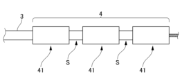
- FIG. 4 is a diagram illustrating another configuration of the visibility unit 4
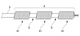
- FIG. 4 is a diagram illustrating another configuration of the visibility unit 4
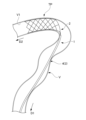
- FIG. 4 is a diagram explaining the distal stabilizer 1 in which the delivery wire 3 has erroneously entered the aneurysm AN in the biological lumen V.
- FIG. 10 is a diagram illustrating the distal stabilizer 1 with the delivery wire 3 returned from the aneurysm AN into the biological lumen V
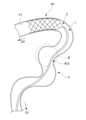
- 4 is a diagram illustrating the distal stabilizer 1 with the delivery wire 3 slackened within the biological lumen V.
- FIG. 10 illustrates the distal stabilizer 1 in a state in which the delivery wire 3 is subjected to an excessive tension load within the biological lumen V.
- FIG. FIG. 10 is a diagram illustrating the distal stabilizer 1 with the delivery wire 3 returned to the biological lumen V without slack.
- 4 is a photographic image showing the distal stabilizer 1 with the delivery wire 3 loosened within the biological lumen V.
- FIG. 10 is a photographic image showing the distal stabilizer 1 with the delivery wire 3 slackened back within the biological lumen V.
- FIG. It is a figure explaining the structure of the deformation
- FIG. It is a figure explaining the structure of the deformation
- FIG. It is a figure explaining the structure of the deformation
- FIG. It is a figure explaining the structure of the deformation
- FIG. 10 is a figure explaining the structure of the deformation
- FIG. 1 shows a delivery system 10 comprising a distal stabilizer 1 according to a first embodiment.
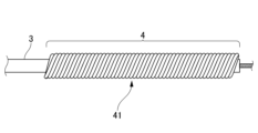
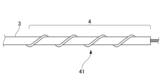
- 2A and 2B are diagrams illustrating another configuration of the visibility section 4.
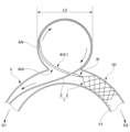
- FIG. 3A and 3B are diagrams illustrating the distal stabilizer 1 in which the delivery wire 3 has erroneously entered the aneurysm AN in the biological lumen V.
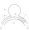
- FIG. 4 is a diagram illustrating the distal stabilizer 1 with the delivery wire 3 returned from the aneurysm AN into the biological lumen V.
- the delivery system 10 shown in FIG. 1 is a system used for delivery of therapeutic devices in biological lumens.
- the blood vessel of the body lumen in which the delivery system 10 is used is not particularly limited, but typically includes highly tortuous cerebral blood vessels.
- an example in which the delivery system 10 is used in a cerebral blood vessel in which an aneurysm exists will be described.
- the delivery system 10 comprises a distal stabilizer 1 and multiple catheters including a first catheter 5 and a second catheter 6 .
- Distal stabilizer 1 is a device used for catheter delivery in a biological lumen.
- the distal stabilizer 1 comprises an anchoring stent 2 and a delivery wire (linear delivery member) 3.
- the anchoring stent 2 extends from the distal end 3f of the delivery wire 3, and is an anchor device that can be anchored to the inner wall V1 (see FIG. 3) of the biological lumen V by self-expanding force.
- the biological lumen is not particularly limited, and may be blood vessels (arteries, veins) of the brain, coronary vessels, upper and lower limbs, organs, and the like.
- the anchoring stent 2 includes a body portion 21 and an antenna 22 .
- the main body part 21 is, for example, a mesh-like structure, and is inserted into the first catheter 5 in a reduced diameter state.
- FIG. 1 shows a state in which the body portion 21 is expanded in diameter.
- the antenna 22 is a portion that focuses the proximal end 21n of the body portion 21 onto the delivery wire 3 .
- the anchoring stent 2 has markers made of radiopaque material at its distal and proximal ends.
- the marker of the anchoring stent 2 is a mark for confirming the positions of the distal end and the proximal end of the anchoring stent 2 in an X-ray image, and is a visibility part 4 (described later) provided on the delivery wire 3. ).
- the delivery wire 3 is a member used when advancing or retracting the anchoring stent 2 within the biological lumen.
- the delivery wire 3 is sent out to the distal side D2 when advancing the locking stent 2 within the biological lumen V, and to the proximal side D1 when retracting the locking stent 2 within the biological lumen V. be drawn in.
- the delivery wire 3 is made of, for example, a material with a high elastic modulus such as stainless steel.
- the diameter of the delivery wire 3 is not particularly limited as long as it has physical properties sufficient for advancing and retreating within the biological lumen V and is compatible with the first catheter 5. For example, the diameter is 0.005 mm. may be ⁇ 0.018 inch.
- the delivery wire 3 has a visibility section 4 .
- the visibility part 4 is provided along the axial direction from the distal end 3f of the delivery wire 3 toward the proximal side D1.
- the visibility portion 4 is a structure including an X-ray opaque portion 41 (described later) that is bendable in the axial direction LD together with the delivery wire 3 .
- the X-ray opaque portion 41 is a portion with high X-ray opacity. Therefore, the X-ray opaque portion 41 has higher visibility than other portions in an X-ray transmission image obtained by X-ray irradiation. As will be described later, the X-ray opaque portion 41 serves as a mark for visually confirming that part of the delivery wire 3 has erroneously entered the aneurysm AN in the X-ray image.
- Radio-opaque materials forming the radio-opaque portion 41 include, for example, platinum, gold, tantalum, platinum, tungsten, iridium, platinum-tungsten, and alloy materials thereof. Examples of alloy materials include radiopaque polymer materials to which radiopaque fillers are added.
- an X-ray transmission image is captured by an X-ray imaging device (not shown).
- An X-ray imaging device is a device that captures an X-ray transmitted image as a moving image or a still image.
- the operator can visually recognize the behavior of the delivery wire 3 and the visibility unit 4 in the living body lumen in real time by displaying the X-ray transmission moving image captured by the X-ray imaging device on the monitor screen.
- the operator can visually recognize the state of the delivery wire 3 and the visibility unit 4 in the living body lumen by projecting the X-ray transmission still image captured by the X-ray imaging device on the monitor screen.
- the X-ray opaque portion 41 is desirably provided in 10% or more of the surface area of the visibility portion 4.
- the radiopaque portion 41 is configured by a tubular member that covers the outer peripheral surface of the delivery wire 3 .
- the X-ray opaque portion 41 configured by a tubular member is continuous in the axial direction and covers the entire surface area of the visibility portion 4 . That is, in the configuration of the first embodiment, the X-ray opaque portion 41 is formed on 100% of the surface area of the visibility portion 4 .
- the visibility part 4 of the present embodiment can be produced, for example, by extrapolating the tubular radiopaque part 41 to the delivery wire 3 .
- the configuration in which the X-ray opaque portion 41 is formed on 100% of the surface area of the visibility portion 4 is an example, and is not limited to this example. Also, as will be described later, the radiopaque portion 41 may be discontinuous in the axial direction of the visibility portion 4 .
- the outer diameter of the visibility part 4 is not particularly limited as long as it fits the first catheter 5, and may be, for example, 0.1 to 1 mm.
- the axial length L1 of the visibility portion 4 depends on the biological lumen in which the delivery system 10 is used, but it is sufficient to deliver the target catheter to the vicinity of the target position TP for treatment of an aneurysm AN, which will be described later. In applications, for example, 30-100 mm.
- the length L1 of the visibility portion 4 is not particularly limited, for example, as shown in FIG. 3, it may be equal to or longer than the estimated neck length L2 of the aneurysm AN.
- the distal stabilizer 1 is a biological tube that satisfies, for example, a ratio between the estimated neck length L2 of the aneurysm AN and the axial length L1 of the visibility portion 4 of 1:1 to 1:20. It is preferably used for cavities.
- the axial length L1 of the visibility portion 4 is, as in the second embodiment (described later), in the application of delivering the target catheter to the vicinity of the target position TP on the distal side in a curved blood vessel, For example, 10 to 500 mm.
- the relationship between the use of the distal stabilizer 1 and the axial length L1 of the visibility portion 4 in the use is not limited to the above example, and can be selected as appropriate.
- the axial length L1 of the visibility portion 4 is preferably as long as possible.
- the length L1 may be 100% of the axial length of the delivery wire 3 .
- the radiopaque portion 41 of the visibility portion 4 is not limited to the tubular shape shown in FIG. 1, and may have other configurations.
- 2A and 2B show an example in which the X-ray opaque portion 41 of the visibility portion 4 is made of a wire-like member.
- a wire-shaped material that is opaque to X-rays is wound around the delivery wire 3 without gaps.
- a wire-shaped material that is opaque to X-rays is wound around the delivery wire 3 with a gap.
- the visibility section 4 is not limited to the example of the embodiment, and can be configured in various forms.
- the delivery wire 3 is fitted with the first catheter 5 .
- the first catheter 5 is, for example, a catheter called a microcatheter.
- a second catheter 6 (described later) is fitted over the first catheter 5 .
- the diameter of the first catheter 5 is set according to the target position TP and the inner diameter and tortuosity of the biological lumen V of the route leading to it, and is not particularly limited, but the inner diameter is preferably 0.017 inch or less, more preferably 0.0165 inches or less.
- the catheter one or a plurality of other catheters (not shown) inserted over the second catheter 6 may be used as necessary.
- a large number of catheters will eventually allow catheters with large inner diameters to be inserted and advanced into the biological lumen V.
- a catheter having an inner diameter larger than that of the first catheter 5 is also called a target catheter.
- a purpose catheter is a catheter having an inner diameter sufficient to insert a therapeutic device or to use itself as a therapeutic device.
- the purpose catheter is sometimes referred to as a guiding catheter in the application of inserting therapeutic devices.
- Treatment devices include, for example, thrombus aspiration devices, flow diverters, aneurysm embolization devices, thrombus removal devices (such as stent retrievers), stents for treating aneurysms, stents for treating intracranial artery stenosis, balloon catheters, shunts, and liquids.
- Embolic material release means such as a catheter with a lumen for passage of liquid embolic material, may be included.
- the purpose catheter may itself be used as a therapeutic device.
- the target catheter is sometimes referred to as a thrombus aspiration catheter.
- a case where the second catheter 6 is the target catheter will be described as an example.
- a biological lumen V is a blood vessel.
- the distal stabilizer 1 and the delivery system 10 of the present embodiment are preferably used when the blood vessel includes a highly curved and tortuous blood vessel.
- the distal stabilizer 1 and the delivery system 10 of the present embodiment are located in a region where the target position TP is 7 mm or less in the blood vessel inner diameter, specifically less than 2.5 mm (preferably 2.0 mm or less or 1.5 mm or less).
- the target position TP is the area after M2 of the middle cerebral artery (MCA) (M2, M3, M4, etc.), the A1 and A2 areas of the anterior cerebral artery (ACA), and the area after P1 of the posterior cerebral artery (PCA). (P1, P2, etc.), the internal carotid artery (ICA), and the like.
- MCA middle cerebral artery
- ACA anterior cerebral artery
- PCA posterior cerebral artery
- ICA internal carotid artery
- the target position TP is not limited to these, and may be located in a wide range of areas with a blood vessel inner diameter of 0.5 to 10 mm.
- the therapeutic device is delivered to the vicinity of the target position TP while being inserted into the second catheter (target catheter) 6.
- the second catheter 6 When delivering the therapeutic device to the target position TP, first, the second catheter 6 is placed on the proximal side D1 of the biological lumen V (not shown).
- the distal end of the second catheter with a large diameter typically catches on the bends and bifurcations of the biological lumen V, making it difficult to advance further distally. This tendency is particularly noticeable in highly curved and tortuous blood vessels.
- the first catheter 5 is inserted into the second catheter 6, which has become difficult to advance, and is fed into the biological lumen V, pushed out from the distal end of the second catheter 6, and the distal end of the first catheter 5 is pushed out. Place near the target position TP.
- the distal stabilizer 1 (see FIG. 1) is inserted into the first catheter 5 and placed near the target position TP (not shown).
- the anchoring stent 2 of the distal stabilizer 1 is accommodated in the first catheter 5 in a reduced diameter state.
- the locking stent 2 housed in the first catheter 5 is then released from the distal end of the first catheter 5 .
- the locking stent 2 is released by retracting the first catheter 5 to the proximal side D1.
- the anchoring stent 2 released from the distal end of the first catheter 5 self-expands due to its self-expanding force. This self-expansion force acts as a force that pushes the inner wall V1 of the biological lumen V from the inside toward the outside.
- FIG. 3 shows a state in which the first catheter 5 is further retracted to the proximal side D1 than the visibility portion 4 in order to make the shape of the visibility portion 4 easy to understand.
- the retracted position may be the position where the locking stent 2 is released (the position covering the visibility portion 4).
- the first catheter 5 When the distal end of the first catheter 5 is advanced toward the target position TP, the first catheter 5 may stray into the aneurysm AN. Since the first catheter 5 is flexible, it may advance along the inner wall of the aneurysm AN, make one turn, and return to the biological lumen V again. On the other hand, the second catheter 6, which has a larger diameter than the first catheter 5, is likely to get caught on the inner wall of the aneurysm AN. It becomes difficult to return to the biological lumen V from inside the aneurysm AN.
- the second catheter 6 with a large diameter has a higher rigidity (harder) than a catheter with a small diameter such as the first catheter 5, there is a possibility that it may break through the inner wall of the aneurysm AN if it strays into the aneurysm AN. be. Therefore, it is required to prevent the second catheter 6 having a large diameter from straying into the aneurysm AN.
- radiopaque markers are placed only at the distal end and the proximal end of the anchoring stent 2, so the delivery wire to the aneurysm does not reach the aneurysm in the radiographic image. Straying cannot be seen.
- the visibility part 4 will be It bends in the axial direction together, and the shape in the axial direction changes. Therefore, the operator can more reliably and quickly grasp that the delivery wire 3 and the first catheter 5 have erroneously entered the aneurysm AN in the X-ray transmission image. This is because, if the delivery wire 3 and the first catheter 5 do not erroneously enter the aneurysm AN, the visibility part 4 follows the opening AN1 of the aneurysm AN with little change in shape in the axial direction.
- the anchoring stent 2 is anchored to the inner wall V1.
- an operation is performed to pull the delivery wire 3 to the proximal side D1.
- the path of the delivery wire 3 within the biological lumen V is shortened, so that the delivery wire 3 can be returned to the biological lumen V from within the aneurysm AN as shown in FIG.
- the above-described pulling operation is appropriately performed, and if necessary, the subsequent advancing operation is appropriately performed to bring the delivery wire 3 along the opening AN1 of the aneurysm AN. can be done.
- the second catheter 6, which has a larger inner diameter than the first catheter 5 is inserted into the delivery wire 3 and the first catheter 5 and advanced, the second catheter 6 moves along the opening AN1 of the aneurysm AN. Therefore, it can be easily delivered to the vicinity of the target position TP. A therapeutic device inserted into the second catheter 6 can then be delivered to the aneurysm AN.
- the delivery wire 3 and the first catheter 5 can be separated by pulling the delivery wire 3 to the proximal side D1. can be returned to the biological lumen V from within the aneurysm AN.
- the second catheter 6 having a larger inner diameter than the first catheter 5 is inserted into the delivery wire 3 and advanced, the second catheter 6 can be easily delivered to the vicinity of the target position TP.
- FIG. 2 shows an example in which the locking stent 2 is anchored near the aneurysm AN
- the target position TP may exist further distally than the aneurysm AN. Even in such a case, the operator can more reliably and quickly grasp that the delivery wire 3 has strayed into the aneurysm AN in the X-ray transmission image.
- the distal stabilizer 1 having the visibility portion 4 of an appropriate length, the distal In the X-ray transmission image when the distal end passes through the aneurysm AN, it can be seen that the delivery wire 3 and the first catheter 5 have wandered into the aneurysm AN. Then, after anchoring the distal end of the first catheter 5 to the target position TP at the distal end of the aneurysm AN, the delivery wire 3 and the delivery wire 3 are pulled toward the proximal side D1. 1 catheter 5 can be returned to the biological lumen V from within the aneurysm AN. In this case as well, the length L1 (see FIG.
- the visibility portion 4 is set to be equal to or greater than the estimated neck length L2 (L1 ⁇ L2) of the aneurysm AN, so that the visibility portion 4 can be seen from any part of the artery. Even if the aneurysm AN is strayed, the practitioner can visually recognize that part of the delivery wire 3 is strayed into the aneurysm AN in the X-ray transmission image.
- the distal stabilizer 1 of the first embodiment described above for example, the following effects can be obtained.
- the visibility part 4 bends in the axial direction together with the delivery wire 3, and the shape in the axial direction changes. Therefore, the practitioner can more reliably and quickly grasp that the delivery wire 3 has errantly entered the aneurysm AN in the X-ray transmission image.
- the operator pulls the delivery wire 3 to the proximal side D1 the behavior of the delivery wire 3 can be visually recognized in the X-ray transmission image, so the operator can operate the delivery wire 3 at an appropriate speed and force.
- the operator when returning the delivery wire 3 that has strayed into the aneurysm AN into the biological lumen V, the operator can use not only his own knowledge and experience but also visual
- the delivery wire 3 can be operated appropriately while referring to the relevant information (X-ray transmission image). Therefore, the operator can more safely carry out the procedure of returning the delivery wire 3 that has errantly entered the aneurysm AN into the biological lumen V.
- the visibility section 4 is provided along the axial direction from the distal end 3f of the delivery wire 3 toward the proximal side D1. Therefore, in the X-ray transmission image, it is possible to more reliably grasp the shape change in the axial direction of the visibility portion 4 provided on the delivery wire 3 .
- the distal stabilizer 1 of the first embodiment by setting the length L1 of the visibility portion 4 to be equal to or longer than the estimated neck length L2 of the aneurysm AN, it is possible to prevent the visibility portion 4 from straying into the aneurysm AN. Even so, the operator can grasp that the delivery wire 3 has strayed into the aneurysm AN in the X-ray transmission image. More specifically, in the distal stabilizer 1 of the first embodiment, the ratio between the estimated neck length L2 of the aneurysm AN and the axial length L1 of the visibility portion 4 satisfies 1:1 to 1:20. It is preferably used for biological lumens.
- the axial length of the visibility part 4 is set to 30 to 100 mm. , the reduction in flexibility of the delivery wire 3 on the distal side can be suppressed, and the visibility part 4 can be axially bent together with the delivery wire 3 when the delivery wire 3 erroneously enters an aneurysm in the biological lumen V. can.
- the radiopaque portion 41 is provided in 10% or more of the surface area of the visibility portion 4. Therefore, in the X-ray transmission image, the operator can more clearly view the change in shape when the visibility part 4 is bent in the axial direction together with the delivery wire 3 .
- the radiopaque portion 41 of the visibility portion 4 is configured by a tubular member provided on the outer peripheral surface of the delivery wire 3, in the radiographic image, The change in shape when the visibility part 4 is bent in the axial direction together with the delivery wire 3 can be visually recognized more linearly. A similar effect can be obtained when the X-ray opaque portion 41 is continuously provided in the axial direction of the visibility portion 4 .
- the radiopaque portion 41 of the visibility portion 4 is composed of a wire-like member wound around the outer peripheral surface of the delivery wire 3, the distal side of the delivery wire 3 It is possible to ensure good visibility in an X-transmissive image while suppressing a decrease in flexibility in . As will be described later, similar effects can be obtained when the X-ray opaque portions 41 are discontinuously provided in the axial direction of the visibility portion 4 .
- FIG. 5 is a diagram explaining the distal stabilizer 1 in a state where the delivery wire 3 is loosened inside the biological lumen V.
- FIG. FIG. 6 is a diagram illustrating the distal stabilizer 1 in a state where the delivery wire 3 is subjected to an excessive tension load within the biological lumen V.
- FIG. 7 is a diagram illustrating the distal stabilizer 1 with the delivery wire 3 returned to the biological lumen V without slack.
- FIG. 8 is a photographic image showing the distal stabilizer 1 with the delivery wire 3 loosened within the biological lumen V.
- FIG. FIG. 9 is a photographic image showing the distal stabilizer 1 with the delivery wire 3 returned to the biological lumen V without slack.
- 8 and 9 are X-ray transmission images of the distal stabilizer 1 inserted into the biological lumen. 8 and 9 show images obtained by cutting out a part of the moving image captured by the X-ray imaging device as a still image. 5 to 7 are schematic diagrams created based on the photographic images shown in FIGS. 8 and 9 to facilitate understanding of the second embodiment.
- the locking stent 2 is locked to the inner wall V1 on the distal side D2 inside the biological lumen V.
- the anchoring stent 2 is anchored to the inner wall V1 located in the region A indicated by the dashed line, although it does not appear in the radiographic images shown in FIGS.
- the delivery wire 3 When the delivery wire 3 is pushed to the distal side D2, the delivery wire 3 may be greatly loosened inside the biological lumen V as shown in FIG. 5 (FIG. 8).
- the distal side of the delivery wire 3 (covered with the visibility portion 4) is slack in a meandering region B of the body lumen V in a ring shape.
- the slackened portion may enter other blood vessels, or the tip of the target catheter may be unintended when the target catheter is delivered. This causes problems such as damage to the blood vessel wall.
- the practitioner can appropriately operate the delivery wire 3 by referring to the X-ray transmission moving image or still image of the distal stabilizer 1 captured in the following procedure. .
- the operator uses an X-ray imaging device to capture an X-ray transmission moving image of the visibility section 4 (first step). Then, while observing the behavior of the visibility part 4 (delivery wire 3) displayed on the monitor screen, the practitioner delivers the catheter while operating the delivery wire 3 at an appropriate speed and force.
- the delivery wire 3 to deliver the first catheter 5 and the second catheter (target catheter) 6, as will be described later, the slack is eliminated by pulling the delivery wire 3, and if the delivery wire 3 is pulled excessively. to ensure proper catheter routing. Even during such an operation, the moving image of the visibility section 4 is continuously captured (second step).
- the moving image of the visibility part 4 is continuously captured (third step). While referring to the X-ray transmission images captured in the above-described first to third steps, the operator delivers the catheter and operates the delivery wire 3 to operate the catheter and delivery within the biological lumen V. The wire 3 can be pushed into the distal side D2 so as not to loosen.
- the practitioner can perform the second imaging method.
- the practitioner continuously captures X-ray transmission moving images of the visibility section 4 using an X-ray imaging device. Then, while observing the behavior of the visibility part 4 (delivery wire 3) displayed on the monitor screen, the practitioner delivers the catheter while operating the delivery wire 3 at an appropriate speed and force.
- the slack is eliminated by pulling the delivery wire 3, and if the delivery wire 3 is pulled excessively. to ensure proper catheter routing. Before such an operation of pushing or pulling the delivery wire 3, an image (moving image or still image) of the visibility section 4 is captured (first step).
- the image of the visibility section 4 is captured (second step).
- the operator delivers the catheter and operates the delivery wire 3 while referring to the X-ray transmission images captured in the first and second steps described above, thereby moving the catheter and the delivery wire within the biological lumen V. 3 can be pushed into the distal side D2 so that it does not come loose.
- the loose delivery wire 3 may stray into a blood vessel different from the target position TP.
- the tip of the second catheter (target catheter) 6 may be directed in an unintended direction to avoid damage to the blood vessel wall.
- the delivery wire 3 is pushed into the distal side D2
- the loosened delivery wire 3 and the first catheter 5 extrapolated therefrom may damage the blood vessel, and the forced pushing of the delivery wire 3 may cause damage to the blood vessel. , the risk of damage to the treatment device can be reduced.
- the distal stabilizer 1 of the present embodiment even if the distal side D2 of the delivery wire 3 is loosened in the biological lumen V, the distal side of the delivery wire 3 can be loosened as shown in FIG. Since the visibility part 4 provided in D2 slackens in the same shape as the delivery wire 3 (not shown), the operator can see the delivery wire through the X-ray transmission image (moving image or still image) projected on the monitor screen. The presence or absence of slack on the distal side D2 of 3 and its size and shape can be visually recognized more reliably and more quickly.
- the operator who visually recognizes the looseness of the delivery wire 3 locks the locking stent 2 to the inner wall V1 of the biological lumen V in order to eliminate the looseness. Then, an operation is performed to pull the delivery wire 3 to the proximal side D1. At this time, the practitioner operates the delivery wire 3 at an appropriate speed and force while observing the behavior of the visibility part 4 (delivery wire 3) reflected in the X-ray transmission image (moving image or still image). can. Therefore, as shown in FIG. 6, the delivery wire 3 is pulled excessively in order to eliminate the slack of the delivery wire 3, and the anchoring stent 2 applies an excessive tensile load to the blood vessel itself, and the body tube may be damaged.
- the path of the delivery wire 3 within the biological lumen V is shortened.
- the ring-shaped slackened delivery wire 3 can be brought into a slack-free state.
- the slackened delivery wire 3 can be returned to a state without slack.
- the operator when returning the loose delivery wire 3 in the living body lumen V to a state without slack, the operator can use not only his own knowledge and experience but also his visual sense.
- FIG. 10A to 10C are diagrams for explaining the configuration of modified forms of the visibility section 4.
- FIG. FIG. 10A shows a modified form of the tubular visibility part 4 shown in FIG. 1 of the embodiment.
- the visibility section 4 may be configured to include a plurality of tube-shaped radiopaque portions 41 .
- the radiopaque portions 41 are provided discontinuously in the axial direction.
- the gaps S formed between adjacent radiopaque portions 41 may be uniform or non-uniform.
- the length of the gap S is, for example, 1-10 mm.
- FIG. 10B shows a modified form of the wire-like visibility part 4 shown in FIG. 2A of the embodiment.
- the visibility section 4 may be configured to include a plurality of wire-like radiopaque portions 41 .
- the radiopaque portions 41 are discontinuous in the axial direction.
- the gaps S formed between adjacent radiopaque portions 41 may be uniform or non-uniform. The length of the gap S is, for example, 1 to 10 mm.
- FIG. 10C shows another modification of the wire-shaped visibility part 4 shown in FIG. 2A of the embodiment.
- the wire-shaped radiopaque portions 41 of radiopaque material may have different densities in the axial direction.
- FIG. 10C shows an example in which the density of radiopaque portions 41 at both ends in the axial direction in the visibility portion 4 is higher than the density of the radiopaque portions 41 in the central portion in the axial direction.
- the configuration for changing the density of the X-ray opaque portion 41 is not limited to the example of FIG. 10C. It may be lower than the density of the line opaque portion 41 . Also, the density of the radiopaque portions 41 on the axially distal side may be higher than the density of the radiopaque portions 41 on the axially proximal side.
- the visibility part 4 may have, for example, a mesh-like radiopaque portion 41 or a tube-like radiopaque portion 41 having a plurality of fine openings on the outer peripheral surface. may be provided. Further, the visibility section 4 may be configured by appropriately combining the embodiment and the above-described modification.
- the delivery wire 3 made of a metal material was described as the linear delivery member, but the present invention is not limited to this.
- the linear delivery member may be made of, for example, resin or a composite material of metal and resin.
- An anchoring device may be, for example, a balloon.
- the delivery wire 3 is operated based on the captured X-ray transmission moving image.
- An example was described.
- an example of operating the delivery wire 3 based on the captured X-ray transmission image (moving image or still image) in each of the first and second steps has been described.
- the imaging method is not limited to these.
- still images may be captured and the delivery wire 3 may be operated based on those still images.
- the operation of capturing a still image may be repeated, and the delivery wire 3 may be operated based on the still image captured in each step. That is, the imaging at each step may be performed discontinuously, and the delivery wire 3 may be operated based on the captured X-ray transmission still image.
- the imaging method includes a first step of imaging a visibility portion of a distal stabilizer that has been sent into a biological lumen together with a linear delivery member, and the visibility portion during an operation of pushing or retracting the linear delivery member. and a third step of imaging the visibility portion after the operation of pushing or pulling the linear delivery member, wherein the imaging from the first step to the third step includes:
- the method may be performed continuously or discontinuously.
- distal stabilizer 2 anchoring stent (anchor device) 3 Delivery wire (linear delivery member) 4 visibility portion 5 first catheter 6 second catheter 10 delivery system 41 radiopaque portion AN aneurysm AN1 opening TP target location V biological lumen V1 inner wall
Landscapes
- Health & Medical Sciences (AREA)
- Life Sciences & Earth Sciences (AREA)
- Animal Behavior & Ethology (AREA)
- Veterinary Medicine (AREA)
- Public Health (AREA)
- Engineering & Computer Science (AREA)
- Biomedical Technology (AREA)
- Heart & Thoracic Surgery (AREA)
- General Health & Medical Sciences (AREA)
- Anesthesiology (AREA)
- Hematology (AREA)
- Pulmonology (AREA)
- Biophysics (AREA)
- Surgery (AREA)
- Neurosurgery (AREA)
- Reproductive Health (AREA)
- Vascular Medicine (AREA)
- Nuclear Medicine, Radiotherapy & Molecular Imaging (AREA)
- Medical Informatics (AREA)
- Molecular Biology (AREA)
- Media Introduction/Drainage Providing Device (AREA)
Abstract
Description
また、本発明は、病変部位に対する様々な治療において、より安全な手技が可能な遠位スタビライザ及び遠位スタビライザの撮像方法を提供することを第2の目的とする。
図1は、第1実施形態に係る遠位スタビライザ1を備えるデリバリシステム10を示す図である。図2A及び図2Bは、視認性部4の他の構成を説明する図である。図3は、デリバリワイヤ3が生体管腔V内の動脈瘤ANに迷入した遠位スタビライザ1を説明する図である。図4は、デリバリワイヤ3が動脈瘤ANから生体管腔V内に戻された遠位スタビライザ1を説明する図である。
遠位スタビライザ1は、生体管腔中でのカテーテルデリバリに用いられるデバイスである。遠位スタビライザ1は、係止ステント2と、デリバリワイヤ(線状デリバリ部材)3と、を備える。
実施形態の遠位スタビライザ1は、デリバリワイヤ3が動脈瘤ANに迷入すると、視認性部4がデリバリワイヤ3と共に軸方向に屈曲して、軸方向の形状が変化する。そのため、施術者は、デリバリワイヤ3が動脈瘤ANに迷入したことを、X線透過の画像において、より確実に且つより速やかに把握できる。また、施術者は、デリバリワイヤ3を近位側D1に引っ張る際、デリバリワイヤ3の挙動をX線透過の画像で視認できるため、デリバリワイヤ3を適度な速度、力加減で操作できる。このように、本実施形態のデリバリシステム10によれば、動脈瘤ANに迷入したデリバリワイヤ3を生体管腔V内へ戻す際に、施術者は、自らの知見や経験だけでなく、視覚的な情報(X線透過の画像)を参照しながらデリバリワイヤ3を適切に操作できる。そのため、施術者は、動脈瘤ANに迷入したデリバリワイヤ3を生体管腔V内へ戻す手技を、より安全に行うことができる。
次に、第2実施形態として、生体管腔内で弛んだデリバリワイヤ3を、弛みのない状態に戻す際の操作及び遠位スタビライザの撮像方法について説明する。第2実施形態で説明する遠位スタビライザ1は、第1実施形態と同じであるため、第1実施形態と同じ構成部材には同一符号を付し、重複する説明を省略する。
施術者は、X線撮像装置を用いて視認性部4のX線透過の動画像を撮像する(第1ステップ)。そして、施術者は、モニタ画面に映し出された視認性部4(デリバリワイヤ3)の挙動を見ながら、デリバリワイヤ3を適度な速度、力加減で操作しながらカテーテルの送達を行う。施術者がデリバリワイヤ3を利用して第1カテーテル5及び第2カテーテル(目的カテーテル)6を送達する際、後述のように、デリバリワイヤ3を引き込むことで弛みが解消され、過剰に引き込んだ場合には押し込むことで適切なカテーテルのルートが確保される。このような操作の最中においても、継続して視認性部4の動画像の撮像を行う(第2ステップ)。また、施術者がカテーテルを送達しながら、デリバリワイヤ3に対する押し込み又は引き込みの操作を行った後も、継続して視認性部4の動画像の撮像を行う(第3ステップ)。施術者は、上述した第1~第3ステップで撮像されたX線透過の動画像を参照しながら、カテーテルの送達とデリバリワイヤ3の操作を行うことにより、生体管腔V内においてカテーテルやデリバリワイヤ3が弛まないように遠位側D2へ押し込むことができる。
施術者は、第2の撮像方法を行うことができる。施術者は、X線撮像装置を用いて視認性部4のX線透過の動画像を継続的に撮像する。そして、施術者は、モニタ画面に映し出された視認性部4(デリバリワイヤ3)の挙動を見ながら、デリバリワイヤ3を適度な速度、力加減で操作しながらカテーテルの送達を行う。施術者がデリバリワイヤ3を利用して第1カテーテル5及び第2カテーテル(目的カテーテル)6を送達する際、後述のように、デリバリワイヤ3を引き込むことで弛みが解消され、過剰に引き込んだ場合には押し込むことで適切なカテーテルのルートが確保される。このようなデリバリワイヤ3に対する押し込み又は引き込みの操作の前に、視認性部4の画像(動画像又は静止画像)の撮像が行われることになる(第1ステップ)。また、デリバリワイヤ3に対する押し込み又は引き込みの操作を行った後にも、視認性部4の画像の撮像が行われることになる(第2ステップ)。施術者は、上述した第1~第2ステップで撮像されたX線透過の画像を参照しながら、カテーテルの送達とデリバリワイヤ3の操作を行うことにより、生体管腔V内においてカテーテルやデリバリワイヤ3が弛まないように遠位側D2へ押し込むことができる。
図10A~図10Cは、視認性部4の変形形態の構成を説明する図である。図10Aは、実施形態の図1に示すチューブ状の視認性部4の変形形態を示している。図10Aに示すように、視認性部4を、複数のチューブ状のX線不透過性部分41を含む構成としてもよい。図10Aに示す変形形態において、X線不透過性部分41は、軸方向において不連続に設けられている。図10Aに示す変形形態において、隣接するX線不透過性部分41の間に形成される隙間Sは、均等でもよいし、不均等でもよい。図10Aに示す変形形態において、隙間Sの長さは、例えば、1~10mmである。
第1及び第2実施形態では、アンカーデバイスを係止ステントとする例について説明したが、これに限定されない。アンカーデバイスは、例えば、バルーンでもよい。
2 係止ステント(アンカーデバイス)
3 デリバリワイヤ(線状デリバリ部材)
4 視認性部
5 第1カテーテル
6 第2カテーテル
10 デリバリシステム
41 X線不透過性部分
AN 動脈瘤
AN1 開口部
TP 標的位置
V 生体管腔
V1 内壁
Claims (9)
- 生体管腔中でのカテーテルデリバリに用いられる遠位スタビライザであって、
線状デリバリ部材と、
前記線状デリバリ部材の遠位端から延び、生体管腔の内壁に係止可能なアンカーデバイスと、
前記線状デリバリ部材の遠位側に設けられ且つ前記線状デリバリ部材と共に軸方向に屈曲可能なX線不透過性部分を含む視認性部と、
を備える遠位スタビライザ。 - 前記視認性部は、前記線状デリバリ部材の遠位端から近位側に向けて、軸方向に沿って設けられる請求項1に記載の遠位スタビライザ。
- 生体管腔中に形成された瘤の推定ネック長と前記視認性部の軸方向の長さとの比率が、1:1~1:20を満たす生体管腔に対して用いられる請求項1又は2に記載の遠位スタビライザ。
- 前記視認性部の軸方向の長さは、10~500mmである請求項1又は2に記載の遠位スタビライザ。
- 前記X線不透過性部分は、前記視認性部の表面領域の10%以上に設けられる請求項1又は2に記載の遠位スタビライザ。
- 前記X線不透過性部分は、前記線状デリバリ部材の外周面に設けられるチューブ状の部材により構成される請求項1又は2に記載の遠位スタビライザ。
- 前記X線不透過性部分は、前記線状デリバリ部材の外周面に巻き付けられるワイヤ状の部材により構成される請求項1又は2に記載の遠位スタビライザ。
- 前記X線不透過性部分は、前記視認性部の軸方向において、連続又は不連続に設けられている請求項1又は2に記載の遠位スタビライザ。
- 生体管腔内において、請求項1に記載の遠位スタビライザの画像を撮像する撮像方法であって、
生体管腔内に前記線状デリバリ部材と共に送り込まれた前記遠位スタビライザについて、前記線状デリバリ部材に対する押し込み又は引き込みの操作の前に、前記視認性部を撮像する第1ステップと、
前記線状デリバリ部材に対する押し込み又は引き込みの操作の後に、前記視認性部を撮像する第2ステップと、
を含む、遠位スタビライザの撮像方法。
Priority Applications (3)
| Application Number | Priority Date | Filing Date | Title |
|---|---|---|---|
| EP23749672.4A EP4473996A4 (en) | 2022-02-02 | 2023-01-26 | DISTAL STABILIZER AND ITS IMAGING PROCESS |
| JP2023578531A JPWO2023149356A1 (ja) | 2022-02-02 | 2023-01-26 | |
| US18/835,173 US20250242133A1 (en) | 2022-02-02 | 2023-01-26 | Distal stabilizer and method for imaging distal stabilizer |
Applications Claiming Priority (6)
| Application Number | Priority Date | Filing Date | Title |
|---|---|---|---|
| JP2022-015186 | 2022-02-02 | ||
| JP2022015186 | 2022-02-02 | ||
| JP2022091404 | 2022-06-06 | ||
| JP2022-091404 | 2022-06-06 | ||
| JP2022-119164 | 2022-07-27 | ||
| JP2022119164 | 2022-07-27 |
Publications (1)
| Publication Number | Publication Date |
|---|---|
| WO2023149356A1 true WO2023149356A1 (ja) | 2023-08-10 |
Family
ID=87552295
Family Applications (1)
| Application Number | Title | Priority Date | Filing Date |
|---|---|---|---|
| PCT/JP2023/002524 Ceased WO2023149356A1 (ja) | 2022-02-02 | 2023-01-26 | 遠位スタビライザ及び遠位スタビライザの撮像方法 |
Country Status (4)
| Country | Link |
|---|---|
| US (1) | US20250242133A1 (ja) |
| EP (1) | EP4473996A4 (ja) |
| JP (1) | JPWO2023149356A1 (ja) |
| WO (1) | WO2023149356A1 (ja) |
Citations (3)
| Publication number | Priority date | Publication date | Assignee | Title |
|---|---|---|---|---|
| US968221A (en) | 1910-02-08 | 1910-08-23 | Wilcox & White Co | Tracker construction for mechanical music-playing instruments. |
| US20160158500A1 (en) * | 2014-12-05 | 2016-06-09 | George P. Teitelbaum | Anchor device for use with catheters |
| US20200030583A1 (en) * | 2015-02-11 | 2020-01-30 | Covidien Lp | Expandable tip medical devices and methods |
Family Cites Families (1)
| Publication number | Priority date | Publication date | Assignee | Title |
|---|---|---|---|---|
| US5509900A (en) * | 1992-03-02 | 1996-04-23 | Kirkman; Thomas R. | Apparatus and method for retaining a catheter in a blood vessel in a fixed position |
-
2023
- 2023-01-26 US US18/835,173 patent/US20250242133A1/en active Pending
- 2023-01-26 WO PCT/JP2023/002524 patent/WO2023149356A1/ja not_active Ceased
- 2023-01-26 EP EP23749672.4A patent/EP4473996A4/en active Pending
- 2023-01-26 JP JP2023578531A patent/JPWO2023149356A1/ja active Pending
Patent Citations (3)
| Publication number | Priority date | Publication date | Assignee | Title |
|---|---|---|---|---|
| US968221A (en) | 1910-02-08 | 1910-08-23 | Wilcox & White Co | Tracker construction for mechanical music-playing instruments. |
| US20160158500A1 (en) * | 2014-12-05 | 2016-06-09 | George P. Teitelbaum | Anchor device for use with catheters |
| US20200030583A1 (en) * | 2015-02-11 | 2020-01-30 | Covidien Lp | Expandable tip medical devices and methods |
Non-Patent Citations (1)
| Title |
|---|
| See also references of EP4473996A4 |
Also Published As
| Publication number | Publication date |
|---|---|
| EP4473996A4 (en) | 2026-01-07 |
| EP4473996A1 (en) | 2024-12-11 |
| JPWO2023149356A1 (ja) | 2023-08-10 |
| US20250242133A1 (en) | 2025-07-31 |
Similar Documents
| Publication | Publication Date | Title |
|---|---|---|
| US12419646B2 (en) | Medical device delivery member with flexible stretch resistant mechanical release | |
| US11517339B2 (en) | Flexible intravascular treatment devices and associated systems and methods of use | |
| US20180325531A1 (en) | Retrieval of material from vessel lumens | |
| JP2022504291A (ja) | 医療用インプラント送達システム | |
| WO2001091842A1 (fr) | Fil-guide medical | |
| US20050101836A1 (en) | Medical guide wire | |
| JP2010502378A (ja) | ループ先端ワイヤガイド | |
| US11684379B2 (en) | Retrieval of material from vessel lumens | |
| US10028704B2 (en) | Exchange guidewire | |
| US11191555B2 (en) | Retrieval of material from vessel lumens | |
| JP6425981B2 (ja) | 自己拡張型ステント | |
| CN115135286B (zh) | 支架输送系统和内窥镜系统 | |
| CN110251285B (zh) | 渐缩型血管支架 | |
| WO2023149356A1 (ja) | 遠位スタビライザ及び遠位スタビライザの撮像方法 | |
| WO2022004850A1 (ja) | 生体管腔中でのカテーテルデリバリに用いる遠位スタビライザ、治療デバイスのデリバリシステム、及び治療デバイス | |
| WO2022162965A1 (ja) | 生体管腔中でのカテーテルデリバリに用いる遠位スタビライザ、治療デバイスのデリバリシステム、及び治療デバイス | |
| WO2024014485A1 (ja) | 遠位スタビライザ | |
| CN119053291A (zh) | 具有定位窗口的医疗装置递送构件 | |
| EP4209182B1 (en) | Systems and methods for inhibiting premature embolic implant deployment | |
| WO2024241863A1 (ja) | 遠位スタビライザ、遠位スタビライザの撮像方法 | |
| US20260124432A1 (en) | Distal stabilizer | |
| EP4582128A1 (en) | Distal stabilizer | |
| US20250169837A1 (en) | Guidewire and snare apparatus | |
| EP3995169A1 (en) | Catheter | |
| WO2024080366A1 (ja) | 遠位スタビライザ |
Legal Events
| Date | Code | Title | Description |
|---|---|---|---|
| 121 | Ep: the epo has been informed by wipo that ep was designated in this application |
Ref document number: 23749672 Country of ref document: EP Kind code of ref document: A1 |
|
| ENP | Entry into the national phase |
Ref document number: 2023578531 Country of ref document: JP Kind code of ref document: A |
|
| WWE | Wipo information: entry into national phase |
Ref document number: 18835173 Country of ref document: US |
|
| WWE | Wipo information: entry into national phase |
Ref document number: 2023749672 Country of ref document: EP |
|
| NENP | Non-entry into the national phase |
Ref country code: DE |
|
| ENP | Entry into the national phase |
Ref document number: 2023749672 Country of ref document: EP Effective date: 20240902 |
|
| WWP | Wipo information: published in national office |
Ref document number: 18835173 Country of ref document: US |