WO2023149543A1 - 作業機械の監視システム及び作業機械の監視方法 - Google Patents
作業機械の監視システム及び作業機械の監視方法 Download PDFInfo
- Publication number
- WO2023149543A1 WO2023149543A1 PCT/JP2023/003564 JP2023003564W WO2023149543A1 WO 2023149543 A1 WO2023149543 A1 WO 2023149543A1 JP 2023003564 W JP2023003564 W JP 2023003564W WO 2023149543 A1 WO2023149543 A1 WO 2023149543A1
- Authority
- WO
- WIPO (PCT)
- Prior art keywords
- warning
- work machine
- boulder
- bucket
- ground
- Prior art date
- Legal status (The legal status is an assumption and is not a legal conclusion. Google has not performed a legal analysis and makes no representation as to the accuracy of the status listed.)
- Ceased
Links
Images


Classifications
-
- E—FIXED CONSTRUCTIONS
- E02—HYDRAULIC ENGINEERING; FOUNDATIONS; SOIL SHIFTING
- E02F—DREDGING; SOIL-SHIFTING
- E02F9/00—Component parts of dredgers or soil-shifting machines, not restricted to one of the kinds covered by groups E02F3/00 - E02F7/00
- E02F9/24—Safety devices, e.g. for preventing overload
-
- E—FIXED CONSTRUCTIONS
- E02—HYDRAULIC ENGINEERING; FOUNDATIONS; SOIL SHIFTING
- E02F—DREDGING; SOIL-SHIFTING
- E02F9/00—Component parts of dredgers or soil-shifting machines, not restricted to one of the kinds covered by groups E02F3/00 - E02F7/00
- E02F9/26—Indicating devices
- E02F9/264—Sensors and their calibration for indicating the position of the work tool
- E02F9/265—Sensors and their calibration for indicating the position of the work tool with follow-up actions (e.g. control signals sent to actuate the work tool)
-
- E—FIXED CONSTRUCTIONS
- E02—HYDRAULIC ENGINEERING; FOUNDATIONS; SOIL SHIFTING
- E02F—DREDGING; SOIL-SHIFTING
- E02F3/00—Dredgers; Soil-shifting machines
- E02F3/04—Dredgers; Soil-shifting machines mechanically-driven
- E02F3/28—Dredgers; Soil-shifting machines mechanically-driven with digging tools mounted on a dipper- or bucket-arm, i.e. there is either one arm or a pair of arms, e.g. dippers, buckets
- E02F3/36—Component parts
- E02F3/42—Drives for dippers, buckets, dipper-arms or bucket-arms
- E02F3/43—Control of dipper or bucket position; Control of sequence of drive operations
- E02F3/431—Control of dipper or bucket position; Control of sequence of drive operations for bucket-arms, front-end loaders, dumpers or the like
- E02F3/434—Control of dipper or bucket position; Control of sequence of drive operations for bucket-arms, front-end loaders, dumpers or the like providing automatic sequences of movements, e.g. automatic dumping or loading, automatic return-to-dig
-
- E—FIXED CONSTRUCTIONS
- E02—HYDRAULIC ENGINEERING; FOUNDATIONS; SOIL SHIFTING
- E02F—DREDGING; SOIL-SHIFTING
- E02F9/00—Component parts of dredgers or soil-shifting machines, not restricted to one of the kinds covered by groups E02F3/00 - E02F7/00
- E02F9/26—Indicating devices
- E02F9/261—Surveying the work-site to be treated
- E02F9/262—Surveying the work-site to be treated with follow-up actions to control the work tool, e.g. controller
-
- E—FIXED CONSTRUCTIONS
- E02—HYDRAULIC ENGINEERING; FOUNDATIONS; SOIL SHIFTING
- E02F—DREDGING; SOIL-SHIFTING
- E02F9/00—Component parts of dredgers or soil-shifting machines, not restricted to one of the kinds covered by groups E02F3/00 - E02F7/00
- E02F9/26—Indicating devices
- E02F9/267—Diagnosing or detecting failure of vehicles
-
- H—ELECTRICITY
- H04—ELECTRIC COMMUNICATION TECHNIQUE
- H04N—PICTORIAL COMMUNICATION, e.g. TELEVISION
- H04N7/00—Television systems
- H04N7/18—Closed-circuit television [CCTV] systems, i.e. systems in which the video signal is not broadcast
Definitions
- the present disclosure relates to a work machine monitoring system and a work machine monitoring method.
- boulders on the ground at the work site there may be boulders on the ground at the work site. If the work machine steps on a boulder, there is a possibility that the movement of the work machine will be hindered.
- the present disclosure aims to monitor boulders on the ground.
- a judgment criterion setting unit that sets the judgment criterion of, a boulder judgment unit that judges the presence or absence of boulders on the ground in the measurement data based on the judgment criteria, and outputs a warning from the output device based on the judgment of the presence or absence of boulders
- a work machine monitoring system comprising: a warning control;
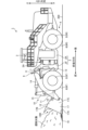
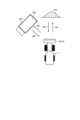
- FIG. 1 is a side view showing the work machine according to the embodiment.
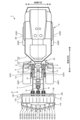
- FIG. 2 is a top view showing the work machine according to the embodiment.
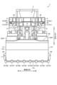
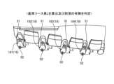
- FIG. 3 is a front view showing the work machine according to the embodiment.
- FIG. 4 is a diagram showing a driver's cab of the driver's cab according to the embodiment.
- FIG. 5 is an enlarged front view of a part of the working machine according to the embodiment.
- FIG. 6 is a diagram showing the drive system of the work machine according to the embodiment.
- FIG. 7 is a diagram explaining the operation of the working machine according to the embodiment.
- FIG. 8 is a diagram explaining the operation of the work machine according to the embodiment.
- FIG. 9 is a side view showing a work machine that carries out loading work according to the embodiment.
- FIG. 10 is a top view showing a working machine that carries out loading work according to the embodiment.
- FIG. 11 is a diagram illustrating an example of imaging data captured by the first imaging device on the left side according to the embodiment;
- FIG. 12 is a diagram illustrating an example of imaging data captured by the second imaging device on the left side according to the embodiment;
- FIG. 15A and 15B are diagrams for explaining a loss determination method by the loss determination unit according to the embodiment;
- FIG. FIG. 16 is a diagram explaining a loss determination method by the loss determination unit according to the embodiment.
- FIG. 17A and 17B are diagrams for explaining a loss determination method by the loss determination unit according to the embodiment;
- FIG. FIG. 18 is a diagram explaining a loss determination method by the loss determination unit according to the embodiment;
- FIG. 19 is a diagram illustrating an example of a soundness determination frame according to the embodiment;
- FIG. 20 is a diagram illustrating an example of a loss determination frame according to the embodiment;
- 21 is a diagram illustrating an example of a symbol indicating bucket teeth displayed on the display device according to the embodiment;
- FIG. FIG. 22 is a diagram showing the relationship between loss determination frames and warning forms according to the embodiment.
- FIG. 23 is a diagram illustrating determination criteria according to the embodiment.
- FIG. 24 is a diagram illustrating warning criteria according to the embodiment.
- FIG. 25 is a diagram illustrating an example of a screen for setting determination criteria and warning criteria according to the embodiment.
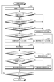
- FIG. 26 is a flowchart showing a work machine defect monitoring method according to the embodiment.
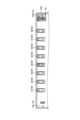
- FIG. 27 is a flow chart showing a method for monitoring boulders on the ground according to the embodiment.
- 28 is a diagram illustrating an example of an output device according to the embodiment;
- FIG. 29 is a diagram illustrating an example of an output device according to the embodiment;
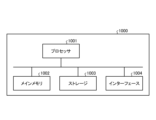
- FIG. FIG. 30 is a block diagram of a computer system according to an embodiment.
- FIG. 31 is a diagram explaining the operation of a work machine according to another embodiment.
- FIG. 32 is a diagram illustrating a monitoring system according to another embodiment;
- FIG. 1 is a side view showing a working machine 1 according to the embodiment.
- FIG. 2 is a top view showing the work machine 1 according to the embodiment.
- FIG. 3 is a front view showing the work machine 1 according to the embodiment.
- the work machine 1 works at the work site.
- the work machine 1 is a wheel loader, which is a type of articulated work machine.
- the work machine 1 performs an excavation work of excavating an excavation target and a loading work of loading an excavated object excavated by the excavation work onto a loading target.
- the work machine 1 includes a vehicle body 2, a cab 3, a travel device 4, a front fender 7, a support member 8, a housing 9, and a work machine 10. and
- the vehicle body 2 includes a front vehicle body 2F and a rear vehicle body 2R.
- the front vehicle body 2F and the rear vehicle body 2R are connected via a joint mechanism 2A.
- the cab 3 is supported by the vehicle body 2.
- a cab is provided in the cab 3 .
- a driver's seat is provided in the driver's cab.
- the work machine 1 is operated by a driver on the cab 3 .
- the traveling device 4 supports the vehicle body 2 and travels on the ground 200 of the work site.
- the traveling device 4 has wheels 5 and tires 6 .
- Tires 6 are mounted on wheels 5 .
- the wheels 5 include front wheels 5F supported by the front vehicle body 2F and rear wheels 5R supported by the rear vehicle body 2R.
- the tire 6 includes a front tire 6F attached to the front wheel 5F and a rear tire 6R attached to the rear wheel 5R.
- the front wheels 5F and front tires 6F are rotatable around the rotation axis FX.
- the rear wheels 5R and the rear tires 6R are rotatable around the rotation axis RX.
- the direction parallel to the rotation axis FX of the front wheels 5F is appropriately referred to as the vehicle width direction.
- the direction perpendicular to the contact surface of the front tire 6F that contacts the ground 200 is appropriately referred to as the vertical direction.
- a direction orthogonal to both the vehicle width direction and the vertical direction is appropriately referred to as the front-rear direction.
- a position or direction near the center CL of the work machine 1 in the vehicle width direction of the work machine 1 is appropriately referred to as an inner side in the vehicle width direction, and a position or direction far from the center CL is appropriately referred to as the vehicle width direction. called the outside of
- One side of the center CL of the work machine 1 in the vehicle width direction is the left, and the opposite side to the left is the right.
- a position or direction close to the work implement 10 with respect to the driver's seat of the cab 3 in the front-rear direction is the front, and the opposite side of the front is the rear.
- a position or direction close to the contact surface of the front tire 6F in the vertical direction is downward, and the opposite side of downward is upward.
- the rear vehicle body 2R is arranged on the rear side of the front vehicle body 2F.
- the front vehicle body 2F bends leftward and rightward with respect to the rear vehicle body 2R.
- the rear wheel 5R is arranged on the rear side of the front wheel 5F.
- the rear tire 6R is arranged on the rear side of the front tire 6F.
- the front wheels 5F and the front tires 6F are arranged on the left and right sides of the center CL of the work machine 1 in the vehicle width direction of the work machine 1, respectively.
- the rear wheels 5R and the rear tires 6R are arranged on the left and right sides of the center CL of the work machine 1 in the vehicle width direction of the work machine 1, respectively.
- the tire 6 is a rotating member that rotates while in contact with the ground 200 .
- the work machine 1 runs on the ground 200 due to the rotation of the tires 6 .
- the front tire 6 ⁇ /b>F is a front rotating member that rotates while in contact with the ground 200 .
- the rear tire 6 ⁇ /b>R is a rear rotating member that is arranged behind the front tire 6 ⁇ /b>F and rotates in contact with the ground 200 .
- the front fender 7 prevents earth and sand scattered from the ground 200 from hitting the vehicle body 2 and the cab 3 while the work machine 1 is running.
- a portion of the front fender 7 is arranged above the front tire 6F.
- a portion of the front fender 7 is arranged behind the front tire 6F.
- the front fenders 7 are arranged on the left and right sides of the center CL of the work machine 1 in the vehicle width direction of the work machine 1 .
- the left front fender 7 is attached to the left portion of the front vehicle body 2F.
- the right front fender 7 is attached to the right portion of the front vehicle body 2F.
- the support member 8 is a rod-shaped member. A lower end portion of the support member 8 is fixed to the front vehicle body 2F. The support member 8 is inclined upwardly forward and outward in the vehicle width direction. The support members 8 are arranged on the left and right sides of the center CL of the work machine 1 in the vehicle width direction of the work machine 1 . A lower end portion of the left support member 8 is fixed to the left portion of the front vehicle body 2F. The left support member 8 is slanted forward and left upward. A lower end portion of the right support member 8 is fixed to the right portion of the front vehicle body 2F. The support member 8 on the right side is inclined upwardly forward and rightward.
- the housing 9 is fixed to the upper end of the support member 8.
- the housing 9 is supported by the front vehicle body 2 ⁇ /b>F via support members 8 .
- the housing 9 is arranged between the joint mechanism 2A and the front end of the front vehicle body 2F.
- the housing 9 is arranged between the upper end of the cab 3 and the upper end of the front vehicle body 2F.
- the housings 9 are arranged on the left and right sides of the center CL of the work machine 1 in the vehicle width direction of the work machine 1 .
- the left housing 9 is fixed to the upper end of the left support member 8 .
- the right housing 9 is fixed to the upper end of the right support member 8 .
- the left housing 9 is arranged above the left front fender 7 .
- the right housing 9 is arranged above the right front fender 7 .
- the work machine 10 operates during excavation work and loading work.
- Work implement 10 is connected to front vehicle body 2F. At least a portion of work implement 10 is disposed forward of front wheels 5F.
- Work implement 10 has boom 11 , bucket 12 , bell crank 15 , and bucket link 16 .
- the boom 11 is rotatably connected to the front vehicle body 2F.
- the boom 11 connects the front vehicle body 2 ⁇ /b>F and the bucket 12 .
- the boom 11 is operated by the driving force generated by the boom cylinder 13 .
- the boom cylinder 13 is a hydraulic cylinder.
- One end of the boom cylinder 13 is connected to the front vehicle body 2F.
- the other end of boom cylinder 13 is connected to boom 11 .
- the boom cylinders 13 are arranged on the left and right sides of the center CL of the work machine 1 in the vehicle width direction of the work machine 1 .
- the bucket 12 excavates the excavation target.
- the bucket 12 is rotatably connected to the tip of the boom 11 .
- the bucket 12 is arranged on the front side of the front wheel 5F.
- Bucket 12 is operated by a driving force generated by bucket cylinder 14 .
- Bucket cylinder 14 is a hydraulic cylinder.
- a central portion of the bellcrank 15 is rotatably connected to the boom 11 .
- One end of the bucket cylinder 14 is connected to the front vehicle body 2F.
- the other end of bucket cylinder 14 is connected to one end of bell crank 15 .
- the other end of bellcrank 15 is connected to bucket 12 via bucket link 16 .
- One bucket cylinder 14 is arranged at the central portion in the vehicle width direction.
- the bucket 12 has a bucket body 17 , bucket teeth 18 , and inter-tooth protectors 19 .
- the bucket body 17 holds the excavated material.
- the bucket body 17 includes a bottom plate portion 17A, an upper plate portion 17B, a left plate portion 17C, and a right plate portion 17D.
- the bottom plate portion 17A, the top plate portion 17B, the left plate portion 17C, and the right plate portion 17D form a holding space in which the excavated material is stored.
- Each of the tip portion of the bottom plate portion 17A and the tip portion of the top plate portion 17B extends in the vehicle width direction.
- Each of the tip of the left plate portion 17C and the tip of the right plate portion 17D extends in the vertical direction or the front-rear direction.
- An opening 12M of the bucket 12 is defined by the tip of the bottom plate 17A, the tip of the top plate 17B, the tip of the left plate 17C, and the tip of the right plate 17D.
- Excavated material can enter the holding space of the bucket 12 through the opening 12M.
- both ends 12E of the bucket body 17 in the vehicle width direction are arranged outside the tire 6 in the vehicle width direction.
- the distance in the vehicle width direction between the left end portion 12E and the right end portion 12E is greater than the distance in the vehicle width direction between the left side surface of the left tire 6 and the right side surface of the right tire 6 .
- the bucket tooth 18 constitutes the cutting edge of the bucket 12 .
- Bucket teeth 18 are attached to the bucket body 17 .
- the bucket tooth 18 is attached to the tip of the bottom plate portion 17A.
- a plurality of bucket teeth 18 are attached to the bucket body 17 .
- the plurality of bucket teeth 18 are arranged at intervals in the vehicle width direction.
- the bucket tooth 18 is a replacement member that is replaceably attached to the bucket body 17 .
- the bucket teeth 18 are fixed to the bucket body 17 by bolts, for example.
- the bucket teeth 18 can be separated from the bucket body 17 by releasing the fixing with the bolts.
- восем ⁇ bucket teeth 18 are arranged at intervals in the vehicle width direction.
- the bucket teeth 18 are arranged in a leftmost bucket tooth 181, a bucket tooth 182 arranged on the left side next to the bucket tooth 181, a bucket tooth 183 arranged on the left side next to the bucket tooth 182, and a bucket tooth 183.
- the inter-tooth protector 19 protects the tip of the bottom plate portion 17A.
- the inter-tooth protector 19 is attached to the bucket body 17 .
- the inter-tooth protector 19 is arranged between a pair of mutually adjacent bucket teeth 18 .
- the inter-tooth protector 19 is attached to the tip of the bottom plate portion 17A.
- a plurality of inter-tooth protectors 19 are attached to the bucket body 17 .
- the plurality of inter-tooth protectors 19 are arranged at intervals in the vehicle width direction.
- the inter-tooth protector 19 is a replacement member that is replaceably attached to the bucket body 17 .
- the inter-tooth protector 19 is fixed to the bucket body 17 by, for example, bolts.
- the inter-tooth protector 19 can be separated from the bucket body 17 by releasing the fixing with the bolt.
- the inter-tooth protector 19 includes an inter-tooth protector 191 arranged on the leftmost side, an inter-tooth protector 192 arranged on the left next to the inter-tooth protector 191, and an inter-tooth protector 193 arranged on the left next to the inter-tooth protector 192. , the inter-tooth protector 194 arranged on the left side next to the inter-tooth protector 193, the inter-tooth protector 195 arranged on the left side next to the inter-tooth protector 194, and the inter-tooth protector arranged on the left side next to the inter-tooth protector 195. 196 and a rightmost inter-tooth protector 197 .
- FIG. 4 is a diagram showing the cab of the cab 3 according to the embodiment.
- FIG. 4 is a diagram schematically showing the scenery seen from the driver seated in the driver's seat in the driver's cab.
- a driving operation device 20, an operation panel 21, a monitor device 22, a rear view monitor device 23, an output device 24, and an input device 25 are arranged in the driver's cab.
- the driving operation device 20 is operated by the driver.
- the driving operation device 20 includes an accelerator pedal 20A and a pair of brake pedals 20B.
- the driving operation device 20 includes a steering lever, a shift lever, a forward/reverse switching switch, and a work lever.
- the travel speed of the work machine 1 is increased by operating the accelerator pedal 20A.
- the brake pedal 20B By operating the brake pedal 20B, the travel speed of the work machine 1 is reduced or the travel of the work machine 1 is stopped.
- the work machine 1 turns by operating the steering lever.
- the speed stage of the work machine 1 is changed by operating the shift lever.
- By operating the forward/reverse changeover switch the traveling direction of the working machine 1 is switched between the forward direction and the reverse direction.
- the work machine 10 is operated by operating the work lever.
- the output device 24 provides output data to the driver.
- the output data contains warnings.
- the output device 24 includes a display device 24A and a sound generator 24B.
- the display device 24A provides display data to the driver as output data.
- a flat panel display such as a liquid crystal display (LCD) or an organic electroluminescence display (OELD) is exemplified as the display device 24A.
- LCD liquid crystal display
- OELD organic electroluminescence display
- the sound generator 24B provides voice data to the driver as output data.
- a buzzer or a speaker is exemplified as the sound generator 24B.
- the input device 25 generates input data by being operated by the driver.
- a button or a keyboard is exemplified as the input device 25 .
- the input device 25 may include, for example, a touch panel.
- a windshield is provided in front of the driver's cab.
- the windshield is attached to a pillar 27 in the cab.
- output device 24 is supported by pillar 27 .
- FIG. 5 is a partially enlarged front view of the working machine 1 according to the embodiment. As shown in FIGS. 3 and 5, the working machine 1 has a headlight 28, a winker lamp 29, a first measuring device 31, and a second measuring device 32. As shown in FIGS.
- the headlamp 28 emits illumination light forward to illuminate the illumination range ahead of the front vehicle body 2F.
- a headlamp 28 is held in the housing 9 .
- the headlamps 28 are arranged on the left and right sides of the center CL of the work machine 1 in the vehicle width direction of the work machine 1 .
- a left headlamp 28 is held in the left housing 9 .
- the right headlamp 28 is held in the right housing 9 .
- the blinker lamp 29 indicates the turning direction of the work machine 1 by lighting or blinking.
- the blinker lamp 29 is held by the housing 9 .
- the winker lamps 29 are arranged on the left and right sides of the center CL of the work machine 1 in the vehicle width direction of the work machine 1 .
- the left blinker lamp 29 is held by the left housing 9 .
- the right winker lamp 29 is held by the right housing 9 .
- the winker lamps 29 are arranged outside the headlights 28 in the vehicle width direction of the work machine 1 .
- the first measuring device 31 measures the working machine 10 .
- the first measurement device 31 acquires measurement data of the work implement 10 .
- the first measuring device 31 is an imaging device that images the working machine 10 .
- the measurement data of work implement 10 includes image data of work implement 10 .
- the first measuring device 31 is appropriately called the first imaging device 31 .
- the second measuring device 32 measures the ground 200 on which the working machine 1 travels.
- the second measurement device 32 acquires measurement data of the ground 200 .
- the second measurement device 32 is an imaging device that images the ground 200 .
- the measurement data of the ground 200 includes image data of the ground 200 .
- the second measuring device 32 is appropriately called the second imaging device 32 .
- Each of the first imaging device 31 and the second imaging device 32 has an optical system and an image sensor into which light that has passed through the optical system is incident.
- an image sensor a CCD (Couple Charged Device) image sensor or a CMOS (Complementary Metal Oxide Semiconductor) image sensor is exemplified.
- Each of the first imaging device 31 and the second imaging device 32 is arranged in the housing 9 .
- Each of the first imaging device 31 and the second imaging device 32 is arranged outside the headlamp 28 in the vehicle width direction of the work machine 1 .
- the second imaging device 32 is arranged above the first imaging device 31 .
- the first imaging devices 31 are arranged on the left and right sides of the center CL of the work machine 1 in the vehicle width direction of the work machine 1 .
- the first imaging device 31 is arranged in each of the left housing 9 and the right housing 9 .
- the first imaging device 31 includes a first imaging device 31L arranged on the left side of the center CL and a first imaging device 31R arranged on the right side of the center CL.
- the second imaging devices 32 are arranged on the left and right sides of the center CL of the work machine 1 in the vehicle width direction of the work machine 1 .
- the second imaging device 32 is arranged in each of the left housing 9 and the right housing 9 .
- the second imaging device 32 includes a second imaging device 32L arranged on the left side of the center CL and a second imaging device 32R arranged on the right side of the center CL.
- FIG. 6 is a diagram showing the drive system 40 of the working machine 1 according to the embodiment.
- the drive system 40 includes an engine 41, a fuel injector 42, a power take off (PTO) 43, a transmission 44, a front axle 45F, a rear axle 45R, a hydraulic pump 46, a control valve 47, and a drive controller 48 .
- PTO power take off
- the engine 41 is, for example, a diesel engine.
- the fuel injection device 42 injects fuel into the cylinders of the engine 41 .
- the driving force of the engine 41 is adjusted by adjusting the amount of fuel injected from the fuel injection device 42 to the engine 41 .
- the power take-off 43 distributes the driving force of the engine 41 to the transmission 44 and the hydraulic pump 46. A driving force of the engine 41 is transmitted to the transmission 44 and the hydraulic pump 46 via the power take-off 43 .
- the transmission 44 has an input shaft to which the driving force of the engine 41 is input, and an output shaft that changes the speed of the driving force input to the input shaft and outputs it.
- the input shaft of transmission 44 is connected to power take-off 43 .
- An output shaft of the transmission 44 is connected to each of the front axle 45F and the rear axle 45R.
- a driving force of the engine 41 is transmitted to the front axle 45F and the rear axle 45R via the power take-off 43 and the transmission 44, respectively.
- the transmission 44 switches the traveling direction of the work machine 1 between the forward direction and the reverse direction.
- the transmission 44 has a forward gear 44F and a reverse gear 44R. By engaging the forward gear 44F, the traveling direction of the work machine 1 is determined to be the forward direction. By engaging the reverse gear 44R, the traveling direction of the work machine 1 is determined to be the reverse direction.
- the front axle 45F transmits the driving force transmitted from the transmission 44 to the front wheels 5F.
- the front wheels 5F rotate based on the driving force transmitted from the front axle 45F.
- the rear axle 45R transmits the driving force transmitted from the transmission 44 to the rear wheels 5R.
- the rear wheel 5R rotates based on the driving force transmitted from the rear axle 45R.
- the working machine 1 By engaging the forward gear 44F, the working machine 1 is ready to move forward. With the forward gear 44F engaged, the accelerator pedal 20A is operated, and the driving force of the engine 41 is transmitted to the front axle 45F and the rear axle 45R via the transmission 44, whereby the working machine 1 moves forward. Even when the forward gear 44F is engaged, the work machine 1 does not move forward, for example, when the brake pedal 20B is being operated.
- the work machine 1 By engaging the reverse gear 44R, the work machine 1 becomes capable of moving backward. With the reverse gear 44R engaged, the accelerator pedal 20A is operated, and the driving force of the engine 41 is transmitted to the front axle 45F and the rear axle 45R via the transmission 44, whereby the work machine 1 moves backward. Note that even when the reverse gear 44R is engaged, the work machine 1 does not move backward, for example, when the brake pedal 20B is being operated.
- the hydraulic pump 46 discharges hydraulic oil.
- the hydraulic pump 46 is a variable displacement hydraulic pump.
- the hydraulic pump 46 is driven by the driving force of the engine 41 .
- Hydraulic oil discharged from the hydraulic pump 46 is supplied to at least one of the boom cylinder 13 and the bucket cylinder 14 via the control valve 47 .
- the control valve 47 controls the flow rate and direction of hydraulic oil supplied to the boom cylinder 13 and the bucket cylinder 14 respectively.
- Work implement 10 is operated by hydraulic oil supplied from hydraulic pump 46 via control valve 47 .
- the drive controller 48 controls the work machine 1 based on the operation signal output from the operation device 20.
- Drive controller 48 includes a computer system.
- FIG. 7 is a diagram explaining the operation of the work machine 10 according to the embodiment.
- the work machine 10 is a front-loading work machine in which the opening 12M of the bucket 12 faces forward during excavation work.
- the operation of raising the boom 11 refers to the operation of rotating the boom 11 so that the tip of the boom 11 is separated from the ground 200 .
- the boom 11 is raised by extending the boom cylinder 13 .
- the operation of lowering the boom 11 refers to the operation of rotating the boom 11 so that the tip of the boom 11 approaches the ground 200 . As the boom cylinder 13 contracts, the boom 11 is lowered.
- the bucket 12 tilts or dumps as the bucket cylinder 14 expands and contracts.
- the tilt operation of the bucket 12 refers to the operation of rotating the bucket 12 so that the tip of the bucket 12 is separated from the ground 200 with the opening 12M of the bucket 12 facing upward.
- Extension of the bucket cylinder 14 rotates the bellcrank 15 such that the upper end of the bellcrank 15 moves forward and the lower end of the bellcrank 15 moves rearward.
- the bucket link 16 When the lower end of the bell crank 15 moves rearward, the bucket 12 is pulled rearward by the bucket link 16 and tilts.
- the object to be excavated is scooped up by the bucket 12 and the excavated material is held by the bucket 12 .
- the dump operation of the bucket 12 refers to the operation of rotating the bucket 12 so that the tip of the bucket 12 approaches the ground 200 with the opening 12M of the bucket 12 facing downward. Contraction of the bucket cylinder 14 rotates the bellcrank 15 such that the upper end of the bellcrank 15 moves rearward and the lower end of the bellcrank 15 moves forward. When the lower end of the bell crank 15 moves forward, the bucket 12 is pushed forward by the bucket link 16 and dumps. The excavated material held in the bucket 12 is discharged from the bucket 12 by dumping the bucket 12 .
- FIG. 8 is a diagram explaining the operation of the work machine 1 according to the embodiment.
- the work machine 1 performs excavation work and loading work at a work site.
- Excavation work is the work of excavating an excavation target.
- natural ground or rocky mountain is exemplified.
- the ground is a mountain made up of earth and sand placed on the ground 200 .
- a rocky mountain is a mountain made up of rocks or stones placed on the ground 200 .
- the excavation target is natural ground 210 .
- Excavated material is a portion of earth 210 excavated and held in bucket 12 .
- the loading work is the work of loading the excavated material excavated by the excavation work into the loading target.
- a transport vehicle, a hopper, or a belt conveyor is exemplified as a loading object.
- the object to be loaded is the dump body 230 of the dump truck 220, which is a type of transport vehicle.
- the work machine 1 is operated by the operator so as to perform cycle work that repeats a series of work modes.
- Cycle work consists of a plurality of interrelated work modes.
- Cycle work includes traveling of the travel device 4 and operation of the work implement 10 .
- cycle work consists of six work modes.
- the sequence of work modes of work machine 1 includes an empty forward mode, a digging mode, a loaded reverse mode, a loaded forward mode, a loading mode, and an empty reverse mode.
- the order of a series of work modes is determined. After the empty advance mode is implemented, the excavation mode is implemented. After the dig mode is implemented, the load reverse mode is implemented. After the load reverse mode is implemented, the load forward mode is implemented. After the cargo advance mode is implemented, the stow mode is implemented. After the loading mode is implemented, the empty reverse mode is implemented.
- the empty advance mode is a work mode in which the work machine 1 advances so as to approach the excavation target while the bucket 12 holds no excavated material.
- the work machine 1 advances to approach the natural ground 210 as indicated by the arrow M1 in FIG.
- the excavation mode is a work mode in which the bucket 12 of the work machine 10 excavates an excavation target. In the digging mode, digging operations are performed. With at least part of the bucket 12 inserted into the natural ground 210 , the bucket 12 is tilted to excavate the natural ground 210 and hold the excavated material in the bucket 12 .
- the loaded reverse mode is a work mode in which the work machine 1 moves backward while the excavated material is held in the bucket 12 so as to separate from the excavation target.
- the work machine 1 moves backward away from the natural ground 210 as indicated by the arrow M2 in FIG.
- the load forward mode is a work mode in which the work machine 1 moves forward so as to approach an object to be loaded while the excavated material is held in the bucket 12 .
- the cargo advance mode the work machine 1 moves forward while turning toward the dump truck 220 as indicated by the arrow M3 in FIG. With the work machine 1 moving forward toward the dump truck 220 , the boom 11 raises so that the bucket 12 is arranged above the dump body 230 .
- the loading mode is a work mode in which excavated material held in the bucket 12 of the work machine 10 is loaded onto a loading target. In the loading mode, loading operations are performed. After the bucket 12 is arranged above the dump body 230 , the excavated material held in the bucket 12 is discharged from the bucket 12 and loaded onto the dump body 230 by dumping the bucket 12 .
- the empty reverse mode is a work mode in which the work machine 1 moves backward so that the bucket 12 does not hold an excavated object and is separated from the object to be loaded.
- the work machine 1 moves backward while turning away from the dump truck 220 as indicated by an arrow M4 in FIG.
- the work machine 1 performs cycle work including an empty forward mode, an excavating mode, a loaded backward mode, a loaded forward mode, a loading mode, and an empty backward mode until the excavated material is loaded onto the dump body 230 at the target load. repeat.
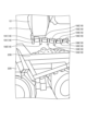
- FIG. 9 is a side view showing the work machine 1 that carries out the loading work according to the embodiment.
- FIG. 10 is a top view showing the work machine 1 that carries out the loading work according to the embodiment.
- the measurement range Ra of the first imaging device 31 includes the imaging range of the first imaging device 31 .
- the measurement range Ra is determined based on the first angle of view ⁇ indicating the angle of view of the optical system of the first imaging device 31 .
- the first image capturing device 31 captures an image of the bucket 12 performing a dumping operation to discharge excavated material to the dump body 230 .
- the first imaging device 31 is fixed to the housing 9 so that the bucket teeth 18 are arranged within the measurement range Ra when the boom 11 is raised and the bucket 12 is dumped.
- the measurement range Rb of the second imaging device 32 includes the imaging range of the second imaging device 32.
- the measurement range Rb is determined based on the second angle of view ⁇ indicating the angle of view of the optical system of the second imaging device 32 .
- the second imaging device 32 images at least the ground 200 in the traveling direction of the tire 6 .
- the second imaging device 32 images the ground 200 in front of the front tires 6F when the work machine 1 moves forward.
- the second imaging device 32 is fixed to the housing 9 so that at least the ground 200 in front of the front tires 6F is arranged in the measurement range Rb when the work machine 1 moves forward.
- the second imaging device 32 is arranged such that the front end portion of the front tire 6F, the ground surface 200 in front of the front tire 6F, and the ground surface 200 outside the front tire 6F in the vehicle width direction are each arranged in the measurement range Rb. It is fixed to the housing 9 as follows.
- the ground surface 200 in front of the front tire 6F includes the ground surface 200 between the front end of the front tire 6F and the rear end of the bucket 12 in the longitudinal direction.
- the second angle of view ⁇ of the second imaging device 32 is wider than the first angle of view ⁇ of the first imaging device 31 .
- the first imaging device 31L on the left side of the center CL images at least the left portion of the bucket 12 of the working machine 10 .
- the first imaging device 31R on the right side of the center CL images at least the right portion of the bucket 12 of the work implement 10 .
- the left portion of bucket 12 is the portion of bucket 12 between left end 12E of bucket 12 and center CL.
- the right portion of bucket 12 is the portion of bucket 12 between right end 12E of bucket 12 and center CL.
- the bucket teeth 181, 182, 183, 184, and 185 of the first imaging device 31L on the left side of the center CL It is fixed to the left housing 9 so as to be arranged in the measurement range Ra.
- Bucket teeth 184, 185, 186, 187, and 188 of the first imaging device 31R on the right side of the center CL are arranged in the measurement range Ra when the boom 11 is raised and the bucket 12 is dumped. , is fixed to the housing 9 on the right side.
- the second imaging device 32L on the left side of the center CL images the ground 200 in front of the front tire 6F on the left side of the center CL.
- the second imaging device 32R on the right side of the center CL images the ground 200 in front of the front tire 6F on the right side of the center CL.
- the second imaging device 32L on the left side of the center CL captures the front end of the left front tire 6F, the ground surface 200 in front of the left front tire 6F, and the left side of the left front tire 6F. and the ground 200 are arranged in the measurement range Rb.
- the measurement range of the second imaging device 32R on the right side of the center CL is the front end of the right front tire 6F, the ground 200 in front of the right front tire 6F, and the ground 200 to the right of the right front tire 6F. It is fixed to the right housing 9 so as to be located at Rb.
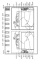
- FIG. 11 is a diagram showing an example of image data captured by the left first imaging device 31L according to the embodiment.
- FIG. 12 is a diagram showing an example of image data captured by the left second imaging device 32R according to the embodiment.
- the first imaging device 31L takes an image of the bucket 12 that is dumping so that the excavated material is discharged to the dump body 230, looking up from below. Thereby, as shown in FIG. 11 , the first imaging device 31L can simultaneously image a plurality of bucket teeth 18 .
- bucket teeth 181 , 182 , 183 , 184 , 185 and 186 are arranged in the measurement range Ra of the first imaging device 31 .
- the second imaging device 32L images the ground 200 in front of the front tire 6F and the ground 200 to the left of the front tire 6F as viewed from above. Thereby, the second imaging device 32L can image the ground 200 around the front tires 6F. For example, when boulders 240 are present on the ground 200 around the front tire 6F, the second imaging device 32L can image the boulders 240 on the ground 200.
- FIG. 12 shows that boulders 240 are present on the ground 200 around the front tire 6F.
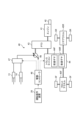
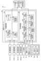
- FIG. 13 is a functional block diagram showing the monitoring system 30 according to the embodiment.
- Work machine 1 has a monitoring system 30 .
- the monitoring system 30 monitors the work machine 10 and the ground 200 on which the work machine 1 travels.
- the monitoring system 30 has a first imaging device 31 , a second imaging device 32 , an output device 24 , an input device 25 and a monitoring controller 33 .
- the first imaging device 31 includes a first imaging device 31L arranged on the left side of the center CL and a first imaging device 31R arranged on the right side of the center CL.
- the second imaging device 32 includes a second imaging device 32L arranged on the left side of the center CL and a second imaging device 32R arranged on the right side of the center CL.
- the first imaging device 31, the second imaging device 32, the output device 24, and the input device 25 are each connected to the monitoring controller 33.
- Image data captured by the first imaging device 31 is input to the monitoring controller 33 .
- Image data captured by the second imaging device 32 is input to the monitoring controller 33 .
- Input data generated by the input device 25 is input to the monitoring controller 33 .
- each of the first imaging device 31 and the second imaging device 32 acquires measurement data at a predetermined sampling rate (SPS: samples per second).
- the measurement data includes image data.
- the sampling rate includes a frame rate (FPS: frames per second).
- Each of the first imaging device 31 and the second imaging device 32 captures image data at a predetermined frame rate.
- a moving image is captured by the first imaging device 31 capturing image data at a predetermined frame rate.
- a moving image is captured by the second image capturing device 32 capturing image data at a predetermined frame rate.
- the monitoring controller 33 has a defect monitoring section 34 and a boulder monitoring section 35 .
- the defect monitoring unit 34 recognizes the presence or absence of defect of the working machine 10 based on the image data captured by the first imaging device 31 .
- the defect monitoring unit 34 causes the output device 24 to output a warning indicating that the work machine 10 has a defect.
- Defects of work implement 10 include defects of bucket 12 .
- Loss of the bucket 12 includes loss of the bucket teeth 18, which are replacement members.
- Loss of the bucket teeth 18 includes falling off of the bucket teeth 18 from the bucket body 17 .
- the boulder monitoring unit 35 recognizes the presence or absence of boulders 240 on the ground 200 on which the work machine 1 travels, based on the imaging data captured by the second imaging device 32 .
- the boulder monitor 35 causes the output device 24 to output a warning indicating that the boulder 240 is on the ground 200 .
- the boulders 240 on the ground 200 include boulders 240 on the ground 200 in the traveling direction of the front tires 6F.
- the boulders 240 on the ground 200 in the traveling direction of the front tires 6F include the boulders 240 on the ground 200 in front of the front tires 6F when the work machine 1 moves forward.
- the loss monitoring unit 34 has a first measurement data acquisition unit 34A, a loss determination unit 34B, a counting unit 34C, and a first warning control unit 34D.
- the first measurement data acquisition unit 34A acquires the measurement data of the working machine 10 from the first imaging device 31 at a predetermined sampling rate.
- the measurement data of work implement 10 includes image data of work implement 10 captured by first imaging device 31 .
- Sampling rate includes frame rate.
- 34 A of 1st measurement data acquisition parts acquire the image data of the working machine 10 from the 1st imaging device 31 at a predetermined frame rate.
- the defect determination unit 34B determines whether or not the working machine 10 is defective based on the image data acquired by the first measurement data acquisition unit 34A. Defect determination unit 34B determines whether or not work implement 10 is deficient in the image data. In the embodiment, the loss determination unit 34B determines whether or not the bucket tooth 18 has fallen off from the bucket body 17 in the image data.
- 14, 15, 16, 17, and 18 are diagrams for explaining the loss determination method by the loss determination unit 34B according to the embodiment.
- a method of determining whether or not the bucket tooth 18 is missing based on image data captured by the first imaging device 31L on the left side of the center CL will be described.
- the first imaging device 31L images the bucket 12 that is dumping to discharge the excavated material to the dump body 230.
- a of 1st measurement data acquisition parts acquire the image data of the bucket 12 from 31 L of 1st imaging devices.
- a plurality of bucket teeth 18 (181, 182, 183, 184, 185) are arranged in the recognition range 50 of the image data.
- Each of the plurality of bucket teeth 18 is attached to the bucket body 17 so as to protrude from the bucket body 17 .
- the loss determination unit 34B recognizes each of the plurality of bucket teeth 18 in the recognition range 50 of the image data acquired by the first measurement data acquisition unit 34A.
- the chipping determination unit 34B estimates the position of the base 51 and the cutting edge 52 of each of the plurality of bucket teeth 18, as shown in FIG.
- the root 51 is the base end of the bucket tooth 18 .
- Root 51 includes the boundary between bucket teeth 18 and bucket body 17 .
- the cutting edge 52 is the tip of the bucket tooth 18 .
- the defect determination unit 34B estimates the root 51 and the cutting edge 52 using artificial intelligence (AI) that analyzes input data with an algorithm and outputs output data.
- the defect determination unit 34B uses artificial intelligence that outputs the probabilities of the probability of the root 51 and the cutting edge 52 based on the input data, and estimates the center where the probability is equal to or greater than a predetermined threshold as the position of the root 51 and the cutting edge 52. You may Further, the defect determination unit 34B may use artificial intelligence that directly estimates the position of the root 51 and the position of the cutting edge 52 based on the input data.
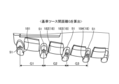
- the loss determination unit 34B calculates the reference tooth-to-tooth distance G based on the distances G1, G2, and G3.
- the reference tooth distance G is the median value of the distances G1, G2, G3.
- the chipping determination unit 34B sets a search range 53 with the root 51 as a reference, and searches for the cutting edge 52 in the search range 53 .
- the search range 53 is set to have a rectangular shape in the image data. As shown in FIG. 17, the size of the vertical search range 53 in the image data is set to [ ⁇ G], and the size of the horizontal search range 53 in the image data is set to [ ⁇ G]. ⁇ and ⁇ are predetermined fixed values.
- the bucket 12 appears large in the image data captured by the first imaging device 31L when the distance between the first imaging device 31L and the bucket 12 is short. In the image data captured by the first imaging device 31L when the distance between the first imaging device 31L and the bucket 12 is long, the bucket 12 appears small. If the sizes of the buckets 12 are different in the image data, the loss determination unit 34B may not be able to search for the cutting edge 52 corresponding to the root 51 . In the embodiment, the search range 53 is set based on the reference distance G between teeth. Thereby, the defect determination unit 34B can search for the cutting edge 52 corresponding to the root 51 regardless of the distance between the first imaging device 31L and the bucket 12 .
- a distance L2 to the cutting edge 52, a distance L3 between the root 51 of the bucket tooth 183 and the cutting edge 52, and a distance L4 between the root 51 of the bucket tooth 184 and the cutting edge 52 are calculated.
- the distance L1 corresponds to the amount of protrusion of the bucket teeth 181 from the bucket body 17 .
- the distance L2 corresponds to the amount of protrusion of the bucket teeth 182 from the bucket body 17 .
- the distance L3 corresponds to the amount of protrusion of the bucket teeth 183 from the bucket body 17 .
- the distance L4 corresponds to the amount of protrusion of the bucket teeth 184 from the bucket body 17 .
- the loss determination section 34B calculates the reference tooth length L based on the distances L1, L2, L3, and L4.
- the reference tooth length L is the median value of the distances L1, L2, L3, L4.
- the loss determination unit 34B determines the distances L5 and L6 corresponding to the four bucket teeth 185, 186, 187, and 188, respectively, based on the image data captured by the first imaging device 31R on the right side of the center CL.
- L7 and L8 may be calculated by a similar method, and the reference tooth length L may be calculated based on the distances L1, L2, L3, L4, L5, L6, L7 and L8.
- the loss determination unit 34B determines a dimension threshold value related to the amount of protrusion of the bucket teeth 18 from the bucket body 17 based on the reference tooth length L.
- the dimension threshold is defined as [ ⁇ L]. ⁇ is a predetermined fixed value. As described above, in the embodiment, the loss determination unit 34B determines the dimension Define a threshold.
- the defect determination unit 34B determines whether or not the bucket teeth 18 (181, 182, 183, 184) have defects based on the dimension threshold.
- the defect determination unit 34B determines that the bucket teeth 18 are defective when the amount of protrusion of the bucket teeth 18 from the bucket body 17 is less than the dimension threshold. If the amount of protrusion of the bucket teeth 18 from the bucket body 17 is greater than or equal to the dimension threshold value, the loss determination unit 34B determines that the bucket teeth 18 are not damaged. In the embodiment, when the amount of protrusion of the bucket teeth 18 is less than the dimension threshold, the defect determination unit 34B determines that the bucket teeth 18 are dropped from the bucket body 17, and the amount of protrusion of the bucket teeth 18 is equal to or greater than the dimension threshold. , it is determined that the bucket teeth 18 have not fallen off the bucket body 17 .
- the bucket 12 appears large in the image data captured by the first imaging device 31L when the distance between the first imaging device 31L and the bucket 12 is short. In the image data captured by the first imaging device 31L when the distance between the first imaging device 31L and the bucket 12 is long, the bucket 12 appears small. If the sizes of the buckets 12 are different in the image data, the defect determination unit 34B may not be able to correctly determine whether or not the bucket teeth 18 are defective. In an embodiment, the dimensional threshold is determined based on the reference tooth length L. Thereby, the loss determination unit 34B can determine whether or not the bucket teeth 18 are damaged regardless of the distance between the first imaging device 31L and the bucket 12 .
- the counting unit 34C classifies the measurement data into a plurality of samples based on the determination by the loss determination unit 34B.
- the counting unit 34C classifies the measurement data determined to have no loss as soundness determination samples.
- the counting unit 34C classifies measurement data determined to have a loss as a loss determination sample.
- the counting unit 34C classifies the measurement data in which the bucket tooth 18 was not recognized by the loss determination unit 34B as an undetermined sample.
- the counting unit 34C counts the number of soundness determination samples indicating measurement data determined to have no defects.
- the counting unit 34C counts the number of loss judgment samples indicating measurement data judged to have a loss.
- the counting unit 34C counts the number of undetermined samples indicating measurement data in which the bucket tooth 18 could not be recognized.
- the measurement data is image data
- the samples classified into the counting section 34C are frames.
- the soundness determination sample will be referred to as a soundness determination frame
- the loss determination sample will be referred to as a loss determination frame
- the undetermined sample will be referred to as an undetermined frame.
- FIG. 19 is a diagram showing an example of a soundness determination frame according to the embodiment.
- a distance L1 indicating the amount of protrusion of the bucket tooth 181
- a distance L2 indicating the amount of protrusion of the bucket tooth 182
- a distance L3 indicating the amount of protrusion of the bucket tooth 183
- a distance indicating the amount of protrusion of the bucket tooth 184 is greater than or equal to the dimension threshold.
- the loss determination unit 34B determines that the bucket tooth 18 is not damaged.
- the counting unit 34C classifies the image data determined to be free of defects as soundness determination frames.
- FIG. 20 is a diagram showing an example of a loss determination frame according to the embodiment.
- the distance L2 indicating the amount of protrusion of the bucket tooth 182 is less than the dimension threshold.
- the loss determination unit 34B determines that the bucket tooth 182 is missing.
- the counting unit 34C classifies the image data determined to have loss as a loss determination frame.
- the method of determining whether or not the bucket tooth 18 has fallen off has been described above based on the image data captured by the first imaging device 31L on the left side of the center CL. The same applies to the method of determining whether or not the bucket tooth 18 has fallen off based on the image data captured by the first imaging device 31R on the right side of the center CL.
- the loss determination unit 34B determines whether or not the four bucket teeth 185, 186, 187, 188 have come off based on the image data acquired by the first measurement data acquisition unit 34A from the first imaging device 31R.
- the first warning control unit 34D causes the display device 24A to display a symbol 60 indicating the bucket tooth 18.
- the first warning control section 34D changes the display form of the symbol 60 based on whether or not the bucket teeth 18 are damaged.
- FIG. 21 is a diagram showing an example of the symbol 60 indicating the bucket tooth 18 displayed on the display device 24A according to the embodiment.
- the first warning control unit 34D displays the symbol 60 indicating the unrecognizable bucket tooth 18 on the display device 24A in the first display mode. display.
- the loss determination unit 34B determines that there is no defect in the bucket tooth 18 in the image data
- the first warning control unit 34D displays the symbol 60 indicating the bucket tooth 18 determined as having no defect in the second display mode. display on device 24A.
- the first warning control unit 34D displays the symbol 60 indicating the bucket tooth 18 determined to be missing in the third display mode. display on device 24A.
- the first warning control unit 34D displays the symbol 60 indicating the bucket teeth 18 that the loss determination unit 34B cannot recognize in the first color.
- the first color is, for example, gray.
- the first warning control unit 34D displays the symbol 60 indicating the bucket tooth 18 determined to have no defect in the second color.
- the second color is green, for example.
- the first warning control unit 34D displays the symbol indicating the bucket tooth 18 determined to have a defect in a third color.
- the third color is red, for example.
- the first warning control unit 34D causes the output device 24 to output a warning indicating that the loss determination frame exists. Also, the first warning control unit 34D changes the form of the warning to be output from the output device 24 based on the number of loss determination frames counted by the counting unit 34C.
- the first warning control unit 34D causes the output device 24 to output a warning in the first form when the number of loss determination frames is less than the sample threshold, and the output device 24 when the number of loss determination frames is equal to or greater than the sample threshold. to output a warning in the second form.
- the sample threshold is a predetermined value.
- the output device 24 includes a display device 24A that displays a symbol 60 indicating the bucket tooth 18, and a sound generator 24B that generates a warning sound.
- the first warning control unit 34D causes the display device 24A to display the display data in the first form when the number of loss determination frames is less than the sample threshold, and the display device 24A when the number of loss determination frames is equal to or greater than the sample threshold. 24A may display the display data in the second form.
- the first warning control unit 34D causes the sound generator 24B to generate a warning sound in the first form when the number of loss determination frames is less than the sample threshold, and causes the sound generator 24B to generate a warning sound in the first mode when the number of loss determination frames is equal to or greater than the sample threshold. 24B may generate a warning sound in a second form.
- FIG. 22 is a diagram showing the relationship between loss determination frames and warning forms according to the embodiment. Determination of the presence/absence of loss determination frames is performed at a predetermined frame rate. In the example shown in FIG. 22, the determination of the presence/absence of loss determination frames takes 0.2 [sec. ] interval. In FIG. 22, the "normal" frame indicates a frame determined as healthy or an undetermined frame. In FIG. 22, the “loss” frame includes the loss determination frame. In the example shown in FIG. 22, the sample threshold is two.
- the moving image captured by the first imaging device 31 when the moving image captured by the first imaging device 31 is composed of one or both of the undetermined frames and the health determination frames, no warning sound is output from the sound generator 24B.
- the symbol 60 indicating the unrecognizable bucket tooth 18 is displayed in the first display mode on the display device 24A.
- the display device 24A displays the symbol 60 indicating the bucket tooth 18 determined to have no defect in the second display mode. .
- a plurality of bucket teeth 18 are attached to the bucket body 17 .
- eight bucket teeth 18 are arranged at intervals in the vehicle width direction.
- the display device 24 ⁇ /b>A displays a plurality of symbols 60 based on respective positions of the plurality of bucket teeth 18 .
- Eight symbols 60 are displayed at intervals according to the positions of the plurality of bucket teeth 181, 182, 183, 184, 185, 186, 187 and 188 on the display device 24A. If the moving image consists of only undetermined frames, all eight symbols 60 are displayed in the first display mode. When the moving image is composed only of soundness determination frames, all eight symbols 60 are displayed in the second display mode.
- the first warning control unit 34D when there is one loss determination frame in the moving image, the first warning control unit 34D causes the sound generator 24B to output the first warning sound. If there are two loss determination frames in the moving image captured by the first imaging device 31, the first warning control unit 34D causes the sound generator 24B to output a second warning sound.
- the first warning control unit 34D when it is determined that each of the image data whose number is less than the sample threshold value continuously acquired by the first measurement data acquisition unit 34A is a loss determination frame, the output device 24 outputs a warning in the first form, and the output device 24 determines that each of the image data of the number equal to or larger than the sample threshold value continuously acquired by the first measurement data acquisition unit 34A is a loss determination frame. to output a warning in the second form.
- the first warning control unit 34D when the sample threshold is 2, if it is determined that each of the image data of less than 2 consecutively acquired by the first measurement data acquisition unit 34A is a loss determination frame, the first warning control unit 34D causes the sound generator 24B to output the first warning sound. In other words, when the image data acquired before and after the loss determination frame is the soundness determination frame or the undetermined frame, the first warning control section 34D causes the sound generator 24B to output the first warning sound. When it is determined that each of the two or more pieces of image data successively acquired by the first measurement data acquisition unit 34A is a loss determination frame, the first warning control unit 34D outputs the second warning from the sound generator 24B. output sound. That is, when the loss determination frame continues at least twice, the first warning control section 34D causes the sound generator 24B to output the second warning sound.
- the first warning control unit 34D may 24B may output a second warning sound.
- sample threshold is arbitrary.
- the sample threshold may be any number greater than or equal to 3, for example.
- the form of warning includes the volume of the warning sound.
- Outputting the warning in the first form includes generating a warning sound at a first volume from the sound generator 24B.
- Outputting the warning in the second mode includes generating a warning sound from the sound generator 24B at a second volume that is higher than the first volume. In the example shown in FIG. 22, the volume of the second warning sound is higher than the volume of the first warning sound.
- the display device 24A displays the symbol 60 indicating the bucket tooth 18 determined to be defective in the third display mode.
- the first warning control unit 34D displays the symbol 60 indicating the bucket tooth 18 determined to have a defect and the symbol 60 indicating the bucket tooth 18 determined to have no defect in different display forms. In the example shown in FIG.
- the first warning control unit 34D when it is determined that the bucket tooth 184 has a defect and it is determined that the bucket teeth 181, 182, 183, 185, 186, 187, and 188 have no defect, the first warning control unit 34D , the symbol indicating the bucket tooth 184 determined to have a defect is displayed in the third display mode, and the symbol indicating the bucket tooth 181, 182, 183, 185, 186, 187, 188 determined to have no defect is displayed in the third display mode. Display in two display modes.
- the boulder monitoring unit 35 includes a second measurement data acquisition unit 35A, a judgment criterion setting unit 35B, a warning criterion setting unit 35C, a standard value storage unit 35D, an input data acquisition unit 35E, an operating state acquisition unit 35F, It has a boulder determining section 35G and a second warning control section 35H.
- the second measurement data acquisition unit 35A acquires measurement data of the ground 200 from the second imaging device 32 at a predetermined sampling rate.
- the measurement data of the ground 200 includes image data of the ground 200 captured by the second imaging device 32 .
- Sampling rate includes frame rate.
- 35 A of 2nd measurement data acquisition parts acquire the image data of the ground 200 from the 2nd imaging device 32 at a predetermined frame rate.
- the second measurement data acquisition section 35A acquires image data of the ground 200 in front of the front tire 6F.
- the judgment criterion setting unit 35B sets the judgment criterion when judging the presence or absence of boulders 240 on the ground 200 in the image data.
- FIG. 23 is a diagram for explaining determination criteria according to the embodiment.
- the criteria include the size of boulder 240 in the image data.
- the dimensions of boulder 240 include the number of pixels of boulder 240 in the image data.
- a threshold for the size of the boulder 240 is set in the image data.
- the threshold for the size of the boulder 240 includes a threshold Px for the size of the boulder 240 in the horizontal direction and a threshold Py for the size of the boulder 240 in the vertical direction.
- the standard value storage unit 35D stores standard values (initial values) related to the determination criteria.
- the standard value is a recommended threshold for the size of boulder 240 .
- the criterion setting unit 35B sets the criterion based on the standard value. In the embodiment, the criterion setting unit 35B sets the threshold for the size of the boulder 240 based on the standard value.
- the threshold is a standard value.
- the warning criterion setting unit 35C sets the warning criterion when outputting a warning from the output device 24.
- FIG. 24 is a diagram for explaining warning criteria according to the embodiment.
- the warning criteria include a warning area 36 established on at least a portion of the ground 200 .
- Setting the warning criteria includes setting the dimensions of the warning area 36 .
- the dimensions of the warning area 36 include the number of pixels of the warning area in the image data. As shown in FIG. 24, the dimension Qx of the warning area 36 in the horizontal direction and the dimension Qy of the warning area 36 in the vertical direction are set in the image data.
- setting the warning area 36 includes setting the position of the warning area 36 .
- Setting the position of the warning area 36 includes setting the position of the warning area 36 in the image data.
- the warning reference setting unit 35C sets the warning area 36 on a portion of the ground 200 in front of the front tire 6F.
- the standard value storage unit 35D stores standard values (initial values) related to warning criteria. The standard values are recommended values for the dimensions and position of the warning area 36 .
- the warning criterion setting unit 35C sets the warning criterion based on the standard value. In the embodiment, the warning criterion setting section 35C sets the size and position of the warning area 36 in the image data based on standard values.
- the input data acquisition unit 35E acquires input data from the input device 25.
- the driver can operate the input device 25 to change the setting of the judgment criteria or change the setting of the warning criteria.
- the criterion setting unit 35B sets the criterion based on the input data.
- the warning criterion setting unit 35C sets the warning criterion based on the input data.
- FIG. 25 is a diagram showing an example of a setting screen for determination criteria and warning criteria according to the embodiment.
- the determination criterion setting unit 35B causes the display device 24A to display a determination criterion setting screen.
- the warning criterion setting unit 35C causes the display device 24A to display a warning criterion setting screen. While viewing the setting screen, the driver can operate the input device 25 to change at least one of the setting of the determination criteria and the setting of the warning criteria.
- the operating state acquisition unit 35F acquires state data indicating the state of the drive system 40.
- Drive controller 48 inputs status data indicating the status of drive system 40 to supervisory controller 33 .
- the operating state acquisition unit 35 ⁇ /b>F determines the state of the drive system 40 based on the state data from the drive controller 48 .
- the state of drive system 40 includes the operating state of transmission 44 .
- the transmission 44 switches the direction of travel of the work machine 1 between the forward direction and the reverse direction.
- Transmission 44 includes a forward gear 44F that operates to move work machine 1 forward, and a reverse gear 44R that operates to move work machine 1 in reverse.
- the boulder determination unit 35G determines the presence or absence of boulders 240 on the ground 200 based on the image data acquired by the second measurement data acquisition unit 35A. The boulder determining unit 35G determines whether there is a boulder 240 on the ground 200 in the image data. In the embodiment, the boulder determination unit 35G determines whether there is a boulder 240 on the ground 200 in front of the front tire 6F in the image data.
- the boulder determination unit 35G may determine whether or not there is a boulder 240, for example, using artificial intelligence (AI) that analyzes input data by an algorithm and outputs output data.
- the boulder determining unit 35G may determine the presence or absence of the boulder 240 using, for example, a pattern matching method.
- the boulder determination unit 35G determines whether or not there is a boulder 240 on the ground 200 in the image data based on the determination criteria.
- the boulder determination unit 35G determines that there is a boulder 240 when the size of the boulder 240 exceeds the threshold (Px, Py), and determines that there is no boulder 240 when the size of the boulder 240 is equal to or less than the threshold (Px, Py). judge.
- the boulder determining unit 35G may determine that there is a boulder 240 when the size of the boulder 240 exceeds one of the threshold value Px and the threshold value Py.
- the boulder determining unit 35G may determine that there is a boulder 240 when the size of the boulder 240 exceeds both the threshold value Px and the threshold value Py.
- the boulder determining unit 35G determines whether there is a boulder 240 in both the state in which the boom 11 is being raised and the state in which it is being lowered.
- the boulder determining unit 35G constantly determines whether or not there is a boulder 240 in the cycle work described with reference to FIG.
- the second warning control unit 35H causes the output device 24 to output a warning based on the presence or absence of boulders 240 on the ground 200 in front of the front tires 6F.
- the second warning control unit 35H causes the output device 24 to output a warning based on the determination of the presence or absence of the boulder 240 by the boulder determination unit 35G and the relationship between the boulder 240 and the warning criteria.
- the warning criteria include a warning area 36 set on at least a portion of the ground 200 .
- a warning area 36 is set on a portion of the ground 200 in front of the front tire 6F.
- the second warning control unit 35 ⁇ /b>H causes the output device 24 to output a warning based on the positional relationship between the boulder 240 and the warning area 36 when it is determined that there is a boulder 240 .
- the second warning control unit 35 ⁇ /b>H causes the output device 24 to output a warning indicating that there is a boulder 240 in the warning area 36 when it is determined that there is a boulder 240 in the warning area 36
- the second warning control unit 35H controls the output device 24 based on state data indicating the state of the drive system 40 acquired by the operating state acquisition unit 35F.
- the state of drive system 40 includes the operating state of transmission 44 .
- the transmission 44 switches the direction of travel of the work machine 1 between the forward direction and the reverse direction.
- the second warning control unit 35H outputs a warning when it is determined that there is a boulder 240 on the ground 200 in the traveling direction of the work machine 1 determined by the transmission 44 . For example, when the transmission 44 is in the neutral state or the reverse gear 44R is engaged, even if it is determined that there is a boulder 240 on the ground 200 in front of the front tire 6F, the second warning control unit 35H detects that there is a boulder 240.
- FIG. 26 is a flowchart showing a defect monitoring method for work implement 10 according to the embodiment.
- the first measurement data acquisition unit 34A acquires image data of the working machine 10 from the first imaging device 31 (step SA1).
- the loss determination unit 34B recognizes the bucket teeth 18 in the image data acquired by the first measurement data acquisition unit 34A, and The cutting edge 52 is estimated (step SA2).
- step SA2 when the bucket tooth 18 is recognized and the root 51 and the cutting edge 52 are estimated (step SA2: Yes), as described with reference to FIG. Distances G1, G2, and G3 of bucket teeth 18 are calculated. Loss determination unit 34B determines whether distances G1, G2, and G3 are equal intervals (step SA3).
- step SA3 If it is determined in step SA3 that the distances G1, G2, and G3 are equidistant (step SA3: Yes), the loss determining unit 34B sets the search range 53 as described with reference to FIG. , the cutting edge 52 corresponding to the root 51 is searched. The defect determination unit 34B determines whether or not the cutting edge 52 has been searched (step SA4).
- step SA4 If it is determined in step SA4 that the cutting edge 52 has been searched (step SA4: Yes), as described with reference to FIG. Define a threshold.
- the defect determination unit 34B determines whether or not the bucket teeth 18 are defective based on the dimension threshold (step SA5).
- step SA5 if it is determined that the bucket tooth 18 in the image data has a defect (step SA5: Yes), the counting unit 34C classifies the image data determined to have a defect into loss determination frames (step SA6 ).
- step SA5 when it is determined that there is no defect in the bucket tooth 18 in the image data (step SA5: No), the counting unit 34C classifies the image data determined as having no defect into soundness determination frames (step SA7). ).
- step SA2 if the bucket tooth 18 cannot be recognized in the image data (step SA2: No), in step SA3, if it is determined that the distances G1, G2, and G3 are not equal in the image data (step SA3: No), and If it is determined in step SA4 that the cutting edge 52 cannot be searched for in the image data (step SA5: No), the counting unit 34C classifies the image data as an undetermined frame (step SA8).
- the counting unit 34C performs time series processing on the classified image data (step SA9).
- the counting unit 34C determines whether or not there is a loss determination frame (step SA10).
- step SA10 If it is determined in step SA10 that there is no loss determination frame (step SA10: No), no warning is output from the output device 24 (step SA11).
- step SA10 determines whether or not there are loss determination frames equal to or greater than the sample threshold. In the embodiment, the counting unit 34C determines whether or not there are at least two successive loss determination frames (step SA12).
- step SA12 If it is determined in step SA12 that the loss determination frame is not consecutive two times (step SA12: No), the first warning control unit 34D outputs a warning in the first form. As described with reference to FIG. 22, in the embodiment, the first warning control unit 34D causes the sound generator 24B to output the first warning sound of the first volume (step SA13).
- step SA12 if it is determined that the loss determination frame continues at least twice (step SA12: Yes), the first warning control unit 34D outputs a warning in the second mode. As described with reference to FIG. 22, in the embodiment, the first warning control unit 34D causes the sound generator 24B to output a second warning sound with a second volume higher than the first volume (step SA14).
- the loss monitoring unit 34 determines whether or not to end the loss monitoring process (step SA15).
- step SA15 If it is determined in step SA15 that the defect monitoring process should be continued (step SA15: No), the process returns to step SA1.
- step SA15 if it is determined that the defect monitoring process has ended (step SA15: Yes), the defect monitoring process ends.
- step SA1 to step SA15 The processing from step SA1 to step SA15 is performed at a predetermined frame rate.
- FIG. 27 is a flow chart showing a boulder monitoring method for the ground 200 according to the embodiment.
- the judgment criterion setting unit 35B sets the judgment criterion when judging the presence or absence of boulders 240 on the ground 200.
- the criterion setting unit 35B sets the threshold value Px and the threshold value Py regarding the size of the boulder 240 based on the standard values stored in the standard value storage unit 35D.
- the criterion setting unit 35B sets the threshold Px and the threshold Py based on the input data (step SB1).
- the warning criterion setting unit 35C sets the warning criterion when outputting a warning from the output device 24.
- 35 C of warning-criteria setting parts set the warning area 36 based on the standard value memorize
- Setting the warning area 36 includes setting the dimensions Qx and Qy, and setting the position of the warning area 36 .
- the warning criterion setting section 35C sets the warning area 36 based on the input data. (Step SB2).
- the second measurement data acquisition unit 35A acquires image data of the ground 200 from the second imaging device 32.
- the second measurement data acquisition unit 35A acquires image data of the ground 200 in front of the front tire 6F (step SB3).
- the operating state acquisition unit 35F acquires state data of the transmission 44 (step SB4).
- the boulder determining unit 35G determines whether or not there is a boulder 240 on the ground 200 in the traveling direction of the work machine 1 determined by the transmission 44 .
- the boulder determining section 35G determines whether or not there is a boulder 240 on the ground 200 in front of the front tire 6F.
- the boulder determining unit 35G determines whether or not there is a boulder 240 on the ground 200 in front of the front tire 6F while the transmission 44 is operating so that the work machine 1 moves forward (step SB5).
- step SB5 When it is determined in step SB5 that there is a boulder 240 on the ground 200 in front of the front tire 6F (step SB5: Yes), the second warning control unit 35H causes the output device 24 to output a warning.
- the second warning control unit 35H outputs a warning from the output device 24 when it is determined that there is a boulder 240 on the ground 200 in front of the front tire 6F while the transmission 44 is operating so that the work machine 1 moves forward. (step SB6).
- step SB5 When it is determined in step SB5 that there is no boulder 240 on the ground 200 in front of the front tire 6F (step SB5: Yes), no warning is output from the output device 24.
- the boulder monitoring unit 35 determines whether or not to end the boulder monitoring process (step SB7).
- step SB7 If it is determined in step SB7 to continue the boulder monitoring process (step SB7: No), the process returns to step SB3.
- step SB7 if it is determined that the boulder monitoring process is finished (step SB7: Yes), the boulder monitoring process is finished.
- step SB3 to step SB7 The processing from step SB3 to step SB7 is performed at a predetermined frame rate.
- FIG. 28 is a diagram showing an example of the display device 24A according to the embodiment.
- the second warning control section 35H causes the display device 24A to display the target image 37 showing the ground 200 generated based on the image data acquired by the second measurement data acquisition section 35A.
- the target image 37 includes a target image 37L representing image data captured by the left second imaging device 32L and a target image 37R representing image data captured by the right second imaging device 32R.
- the target image 37L and the target image 37R are displayed side by side on the display screen of the display device 24A.
- the target image 37L and the target image 37R are simultaneously displayed on the display screen of the display device 24A.
- the target image 37L is displayed in the left area of the display screen of the display device 24A.
- the target image 37R is displayed in the right area of the display screen of the display device 24A.
- the second warning control unit 35H causes the display device 24A to display an area image 360 showing the warning area 36.
- the second warning control unit 35H superimposes the area image 360 on the target image 37 and displays it on the display device 24A.
- An area image 360 showing the warning area 36 set to include the ground 200 in front of the left front tire 6F is displayed on the display device 24A in a state of being superimposed on the target image 37L.
- An area image 360 showing the warning area 36 set to include the ground 200 in front of the right front tire 6F is displayed on the display device 24A in a state of being superimposed on the target image 37R.
- the second warning control unit 35H causes the display device 24A to display the symbol 70 indicating the front tire 6F.
- the symbols 70 include a symbol 70L representing the left front tire 6F and a symbol 70R representing the right front tire 6F.
- the second warning control unit 35H causes the output device 24 to output a warning indicating that there is a boulder 240 on the ground 200 in front of the front tire 6F.
- Making the output device 24 output a warning includes causing the display device 24A to display a warning image indicating that there is a boulder 240 on the ground 200 in front of the front tire 6F.
- Making the output device 24 output a warning includes generating a warning sound from the sound generator 24B indicating that there is a boulder 240 on the ground 200 in front of the front tire 6F.
- the warning image includes a frame image 80 displayed surrounding the boulder 240 in the target image 37, a frame image 81 displayed around the periphery of the target image 37, and a background image 82 of the symbol 70. .
- the second warning control unit 35H causes the display device 24A to display the frame image 80 so that the boulder 240 is emphasized.
- the boulders 240 of the target image 37L are placed outside the warning area 36.
- the boulder determination unit 35G determines that the boulder 240 exists outside the warning area 36
- the second warning control unit 35H causes the display device 24A to display the frame image 80L of the first form.
- the boulder determination unit 35G determines that the boulder 240 exists inside the warning area 36
- the second warning control unit 35H causes the display device 24A to display the frame image 80R of the second form different from the first form.
- the second warning control unit 35H displays the frame image 80L and the frame image 80R such that the boulders 240 placed inside the warning area 36 are emphasized more than the boulders 240 placed outside the warning area 36. display on device 24A.
- the frame image 80R is displayed with a solid line and the frame image 80L is displayed with a dotted line.
- the frame image 80R may be displayed in the first color and the frame image 80L may be displayed in the second color. Red is exemplified as the first color. Green is exemplified as the second color.
- the second warning control unit 35H causes the display device 24A to display the frame image 81 so that the target image 37 in which at least part of the boulder 240 exists inside the warning area 36 is emphasized.
- the boulders 240 displayed in the target image 37R exists inside the warning area 36.
- a boulder 240 displayed in the target image 37L exists outside the warning area 36 .
- the second warning controller 35H causes the display device 24A to display the frame image 81 such that the target image 37R is emphasized more than the target image 37L.
- the second warning control unit 35H causes the display device 24A to display the background image 82 so that the front tires 6F, which are likely to pass over the boulders 240, are emphasized.
- the second warning control unit 35H causes the display device 24A to display the background image 82 of the symbol 70R such that the right front tire 6F, which is likely to pass over the boulder 240, is emphasized.
- the second warning control unit 35H controls the left front tire 6F, which is likely to pass over the boulder 240.
- the background image 82 of the symbol 70L can be displayed on the display device 24A so that the tire 6F is emphasized.
- the first warning control unit 34D causes the display device 24A to display a symbol 60 indicating the bucket tooth 18.
- the first warning control section 34D displays multiple symbols 60 based on the respective positions of the multiple bucket teeth 18 .
- the symbols 60 are a symbol 61 representing a bucket tooth 181, a symbol 62 representing a bucket tooth 182, a symbol 63 representing a bucket tooth 183, a symbol 64 representing a bucket tooth 184, a symbol 65 representing a bucket tooth 185, and a bucket.
- a symbol 66 indicating a tooth 186, a symbol 67 indicating a bucket tooth 187, and a symbol 68 indicating a bucket tooth 188 are included.
- a plurality of symbols 60 are displayed in the upper area of the display screen of the display device 24A.
- the symbol 61 is displayed on the leftmost side
- the symbol 62 is arranged on the left side next to the symbol 61
- the symbol 63 is arranged on the left side next to the symbol 62
- the symbol 64 is displayed next to the symbol 63.
- Symbol 65 is placed next to symbol 64 on the left
- symbol 66 is placed next to symbol 65 on the left
- symbol 67 is placed next to symbol 66 on the left
- symbol 68 is placed next to symbol 66 on the left. placed on the right side.
- FIG. 28 shows an example in which the loss determination unit 34B cannot recognize eight bucket teeth 18 and eight symbols 60 are displayed in the first display mode.
- FIG. 29 is a diagram showing an example of the display device 24A according to the embodiment.
- FIG. 29 is a diagram in which the upper region of the display device 24A is extracted.
- FIG. 29 shows an example of the symbol 60 when the defect determination unit 34B determines whether or not each of the eight bucket teeth 18 is defective.
- the first warning control section 34D changes the display form of the symbol 60 based on whether or not the bucket teeth 18 are damaged.
- the first warning control unit 34D displays the symbol 60 indicating the bucket tooth 18 determined to have a defect and the symbol 60 indicating the bucket tooth 18 determined to have no defect in different display forms. As shown in FIG.
- the first warning control unit 34D a symbol 64 indicating the bucket tooth 184 determined to have a defect is displayed in the third display form, and a symbol 61 indicating the bucket tooth 181, 182, 183, 185, 186, 187, 188 determined to have no defect.
- 62, 63, 65, 66, 67 and 68 are displayed in the second display form.
- the first warning control section 34D causes the display device 24A to display the symbol 64 in the third color, and causes the display device 24A to display the symbols 61, 62, 63, 65, 66, 67, 68 in the second color.
- the third color is red, for example.
- the second color is green, for example.
- FIG. 30 is a block diagram showing a computer system 1000 according to an embodiment.
- Each of the supervisory controller 33 and drive controller 48 described above includes a computer system 1000 .
- a computer system 1000 includes a processor 1001 such as a CPU (Central Processing Unit), a main memory 1002 including non-volatile memory such as ROM (Read Only Memory) and volatile memory such as RAM (Random Access Memory), It has a storage 1003 and an interface 1004 including an input/output circuit.
- the respective functions of the monitoring controller 33 and drive controller 48 described above are stored in the storage 1003 as computer programs.
- the processor 1001 reads a computer program from the storage 1003, develops it in the main memory 1002, and executes the above-described processing according to the program. Note that the computer program may be distributed to the computer system 1000 via a network.
- the computer program or computer system 1000 acquires measurement data of the ground 200 on which the tire 6 of the work machine 1 is in contact and on which the work machine 1 travels due to the rotation of the tire 6, and measures the ground 200. setting a criterion for determining the presence or absence of the boulders 240 on the ground 200 in the data; determining the presence or absence of the boulders 240 on the ground 200 in the measurement data of the ground 200 based on the determination criteria; outputting a warning from the output device 24 based on the determination of the presence/absence.
- the computer program or computer system 1000 acquires the measurement data of the ground 200 on which the tire 6 of the work machine 1 is in contact and on which the work machine 1 travels due to the rotation of the tire 6 and the ground 200 according to the above embodiment. Determining the presence or absence of boulders 240 on the ground 200 in the measurement data, setting a warning standard when outputting a warning from the output device 24, determining the presence or absence of boulders 240, and determining the presence or absence of boulders 240 and the warning standard and causing a warning to be output from the output device 24 based on the relationship.
- the monitoring system 30 acquires image data of the ground 200 on which the tire 6 of the work machine 1 is in contact and on which the work machine 1 travels due to the rotation of the tire 6.
- an acquisition unit 35A a determination criterion setting unit 35B that sets determination criteria for determining the presence or absence of boulders 240 on the ground 200 in the measurement data of the ground 200;
- a boulder determination unit 35G that determines whether or not there is a boulder 240;
- the monitoring system 30 can monitor boulders 240 on the ground 200 while the work machine 1 is working.
- a warning is output from the output device 24 so that the driver can drive without stepping on the boulder 240 with the tires 6 .
- the tire 6 is prevented from being damaged, and the traveling of the work machine 1 is prevented from being hindered.
- the output device 24 properly outputs a warning.
- the monitoring system 30 also includes a warning standard setting unit 35C that sets a warning standard for outputting a warning from the output device 24 .
- the second warning control unit 35H causes the output device 24 to output a warning based on the determination of the presence or absence of the boulders 240 and the relationship between the boulders 240 and the warning criteria. If the warning criteria are set inappropriately, unnecessary warnings may be output or necessary warnings may not be output. In the embodiment, since the warning criteria for outputting the warning from the output device 24 are properly set, the warning is properly output from the output device 24 .
- each of the first imaging device 31 and the second imaging device 32 is arranged in the housing 9 that holds the headlamp 28 . At least one of the first imaging device 31 and the second imaging device 32 may be arranged at a portion of the work machine 1 different from the housing 9 .
- the second imaging device 32 is arranged above the first imaging device 31 . At least part of the second imaging device 32 may be arranged at the same position as the first imaging device 31 in the vertical direction. The second imaging device 32 may be arranged below the first imaging device 31 .
- the defect monitoring unit 34 determines whether or not the bucket 12 is defective based on the image data of the bucket 12 that performs the dumping operation in the cycle work described with reference to FIG.
- the first image capturing device 31 may capture an image of the bucket 12 performing a dumping operation in a work other than the cycle work.
- the defect monitoring unit 34 may determine whether or not the bucket 12 is defective based on the image data of the bucket 12 that is dumped in a work other than the cycle work.
- the image data of the bucket 12 imaged by the first imaging device 31 may not be the image data of the bucket 12 that performs the dump operation, and may be image data that allows the defect monitoring unit 34 to recognize the defect of the bucket 12. .
- the loss of the bucket teeth 18 is assumed to be the falling off of the bucket teeth 18 from the bucket body 17 .
- the loss of the bucket teeth 18 may be wear of the bucket teeth 18 or breakage of the bucket teeth 18 .
- the defect monitoring unit 34 monitors the defect of the bucket tooth 18 as a replacement member.
- the defect monitoring unit 34 may monitor the defect of the inter-tooth protector 19 as a replacement member.
- Deficiency of the inter-tooth protector 19 includes detachment of the inter-tooth protector 19 from the bucket body 17, wear of the inter-tooth protector 19, and breakage of the inter-tooth protector 19.
- setting the warning criteria includes setting the dimensions of the warning area 36 and setting the position of the warning area 36 .
- the setting of the warning criteria may be either setting of the size of the warning area 36 or setting of the position of the warning area 36 .
- the position of the warning area 36 may be a predetermined fixed value, and only the dimensions of the warning area 36 may be set.
- the size of the warning area 36 may be a predetermined fixed value, and only the position of the warning area 36 may be set.
- the boulder monitoring unit 35 determines the presence or absence of the boulders 240 on the ground 200 based on the determination criteria, and causes the output device 24 to output a warning based on the relationship between the boulders 240 and the warning criteria. I decided to The boulder monitoring unit 35 may determine that there is a boulder 240 when both the determination criterion and the warning criterion are satisfied. In this case, the boulder monitoring unit 35 may use the warning criterion as the determination criterion. Further, the boulder monitoring unit 35 may determine the presence or absence of boulders 240 on the ground 200 regardless of the determination criteria, and output a warning when both the determination criteria and the warning criteria are satisfied. In this case, the boulder monitoring unit 35 may use the determination criterion as a warning criterion.
- the second warning control section 35H displays the area image 360 showing the warning area 36 on the display device 24A.
- the second warning control section 35H does not have to display the area image 360 indicating the warning area 36 on the display device 24A.
- the second warning control section 35H may display an area image 360 indicating the warning area 36 on the display device 24A when it is determined that there is a boulder 240.
- the second warning control section 35H may display an area image 360 showing the warning area 36 on the display device 24A when it is determined that there is a boulder 240 within the warning area 36 .
- the second warning control unit 35H outputs when it is determined that there is a boulder 240 on the ground 200 in front of the front tire 6F while the transmission 44 is operating so that the work machine 1 moves forward. A warning is output from the device 24 . Further, by engaging the forward gear 44F in a state in which it is determined that there is a boulder 240 on the ground 200 in front of the front tire 6F, a warning is output from the output device 24 even if the forward movement of the work machine 1 has not started. I decided to Regardless of the state of the transmission 44, the second warning control unit 35H controls the operation when the work machine 1 is traveling in the traveling direction in a state where it is determined that there is a boulder 240 on the ground 200 in the traveling direction of the front tires 6F.
- the output device 24 may output a warning.
- the operating state acquisition unit 35F determines whether the work machine 1 is traveling in the traveling direction based on the detection data of the rotation sensor. can be determined.
- the second warning control unit 35H determines that the operating state acquisition unit 35F determines that the work machine 1 is traveling in the direction of travel, and that the boulder determination unit 35G determines that there is a boulder 240 on the ground 200 in the direction of travel. In this case, a warning may be output from the output device 24 .
- the work machine 1 when the work machine 1 is on a downward slope, the work machine 1 may move forward due to the action of gravity, for example, even when the transmission 44 is in the neutral state or the reverse gear 44R is engaged.
- the second warning control unit 35H outputs the A warning may be output.
- the second warning control unit 35H when it is determined that there is a boulder 240 on the ground 200 in front of the front tire 6F while the work machine 1 is in a state in which it can move forward or is moving forward, the second warning control unit 35H A warning is output from the output device 24 .
- the second warning control unit 35H outputs a warning from the output device 24. You may let
- FIG. 31 is a diagram showing the operation of the working machine 1 according to another embodiment.
- the work machine 1 has a second imaging device 32 that images the ground 200 behind the rear tires 6R.
- the second measurement data acquisition unit 35A acquires image data of the ground 200 behind the rear tire 6R from the second imaging device 32 .
- the second warning control unit 35H outputs a warning from the output device 24 when it is determined that there is a boulder 240 on the ground 200 behind the rear tire 6R while the transmission 44 is operating so that the work machine 1 moves backward. You may let In addition, the second warning control unit 35H determines that the work machine 1 is moving backward, regardless of the state of the transmission 44, and determines that there is a boulder 240 on the ground 200 behind the rear tire 6R. If so, the output device 24 may output a warning.
- the output device 24 is arranged in the operator's cab of the work machine 1.
- the output device 24 may be arranged outside the work machine 1 .
- FIG. 32 is a diagram showing a monitoring system 300 according to another embodiment.
- the work machine 1 is remotely controlled by a driving operation device 20F provided remotely from the work machine 1 .
- Each of the first imaging device 31 and the second imaging device 32 is provided on the work machine 1 as in the above-described embodiment.
- the work machine 1 is provided with a remote-control imaging device (not shown) that takes an image in front of the work machine 1 .
- the remote control imaging device captures image data of the scenery in front of the work machine 1 similar to the scenery seen through the windshield by the driver sitting in the driver's seat in the cab as shown in FIG.
- a part or all of the output device 24F, the input device 25F, the monitoring controller 33F, and the operation device 20F are arranged in a remote control facility provided at a remote location of the work machine 1.
- Each of the output device 24F, the input device 25F, the monitoring controller 33F, and the operation device 20F is provided separately from the work machine 1 .
- the remote control facility is provided with a remote control display device for displaying image data captured by the remote control imaging device.
- the work machine 1 and the monitoring controller 33F wirelessly communicate via a wireless communication system.
- the working machine 1 is provided with a wireless communication device 301 of a wireless communication system, and a wireless communication device 302 of a wireless communication system is connected to the monitoring controller 33F.
- the wireless communication device 301 of the work machine 1 and the wireless communication device 302 of the monitoring controller 33F may communicate via another device.
- the image data captured by the remote control imaging device is transmitted to the remote control display device via the wireless communication system.
- a driver of the remote control facility can operate the operation device 20F while viewing the image data displayed on the remote control display device.
- An operation signal generated by operating the operation device 20F is transmitted to the work machine 1 via the wireless communication system. Thereby, the work machine 1 is remotely operated.
- the monitoring controller 33F has the defect monitoring unit 34 and the boulder monitoring unit 35 as described with reference to FIG.
- the image data captured by the first imaging device 31 and the second imaging device 32 are transmitted from the working machine 1 to the monitoring controller 33F via the wireless communication system.
- the defect monitoring unit 34 of the monitoring controller 33F can determine whether or not the bucket teeth 18 are defective based on the image data captured by the first imaging device 31 . Further, the defect monitoring unit 34 of the monitoring controller 33F can cause the output device 24F to output a warning indicating that the bucket teeth 18 are defective.
- the boulder monitoring unit 35 of the monitoring controller 33F can determine the presence or absence of the boulder 240 on the ground 200 based on the image data captured by the second imaging device 32 . Further, the boulder monitoring unit 35 of the monitoring controller 33F can cause the output device 24F to output a warning indicating that there is a boulder 240 on the ground 200 .
- each of the first measuring device 31 and the second measuring device 32 is an imaging device. At least one of the first measurement device 31 and the second measurement device 32 may be a laser device. At least one of the first measurement device 31 and the second measurement device 32 may be a radar device. A laser device irradiates a measurement target with a laser beam and obtains measurement data of the measurement target. A radar device irradiates an object to be measured with sound waves and acquires measurement data of the object to be measured. The laser device can acquire measurement data of the work machine 10 at a predetermined sampling rate by irradiating the work machine 10 with a laser beam.
- the radar device can acquire measurement data of the work machine 10 at a predetermined sampling rate by irradiating the work machine 10 with sound waves.
- the defect monitoring unit 34 can change the form of the warning to be output from the output device 24 based on the number of defect determination samples indicating measurement data determined to have a defect in the work machine 10 .
- the work machine 1 is a wheel loader.
- the work machine 1 may be other work machines such as bulldozers and hydraulic excavators.
- Each of the bulldozer and the hydraulic excavator has a working machine and a crawler belt that rotates in contact with the ground 200 .
- the track is a rotating member that rotates while in contact with the ground 200 .
- the work machine travels as the crawler belt rotates.
- Rolling stone monitoring unit 35A second measurement data acquisition unit 35B determination criterion setting unit 35C warning criterion setting unit 35D standard value storage unit 35E input data acquisition unit 35F driving state acquisition unit 35G boulder determination unit 35H... Second warning control section, 36... Warning area, 37... Target image, 37L... Target image, 37R... Target image, 40... Drive system, 41... Engine, 42... Fuel injection device, 43... Power take-off, 44... Transmission 44F Forward gear 44R Reverse gear 45F Front axle 45R Rear axle 46 Hydraulic pump 47 Control valve 48 Drive controller 50 Recognition range 51 Root 52 Cutting edge 53 ... search range, 60 ... symbol, 61 ... symbol, 62 ... symbol, 63 ... symbol, 64 ... symbol, 65 ... symbol, 66 ...
Landscapes
- Engineering & Computer Science (AREA)
- Mining & Mineral Resources (AREA)
- Civil Engineering (AREA)
- General Engineering & Computer Science (AREA)
- Structural Engineering (AREA)
- Mechanical Engineering (AREA)
- Multimedia (AREA)
- Signal Processing (AREA)
- Component Parts Of Construction Machinery (AREA)
- Closed-Circuit Television Systems (AREA)
Abstract
Description
図1は、実施形態に係る作業機械1を示す側面図である。図2は、実施形態に係る作業機械1を示す上面図である。図3は、実施形態に係る作業機械1を示す正面図である。
図4は、実施形態に係る運転台3の運転室を示す図である。図4は、運転室の運転席に着座した運転者から見た景色を模式的に示す図である。
図5は、実施形態に係る作業機械1の一部を拡大した正面図である。図3及び図5に示すように、作業機械1は、前照灯28と、ウインカーランプ29と、第1計測装置31と、第2計測装置32とを有する。
図6は、実施形態に係る作業機械1の駆動システム40を示す図である。駆動システム40は、エンジン41と、燃料噴射装置42と、パワーテイクオフ43(PTO:Power Take Off)と、トランスミッション44と、フロントアクスル45Fと、リヤアクスル45Rと、油圧ポンプ46と、制御弁47と、駆動コントローラ48とを有する。
図7は、実施形態に係る作業機10の動作を説明する図である。実施形態において、作業機10は、掘削作業においてバケット12の開口部12Mが前方を向くフロントローディング方式の作業機である。
図8は、実施形態に係る作業機械1の動作を説明する図である。作業機械1は、作業現場において掘削作業及び積込作業を実施する。
図9は、実施形態に係る積込作業を実施する作業機械1を示す側面図である。図10は、実施形態に係る積込作業を実施する作業機械1を示す上面図である。
図13は、実施形態に係る監視システム30を示す機能ブロック図である。作業機械1は、監視システム30を有する。監視システム30は、作業機10及び作業機械1が走行する地面200を監視する。
欠損監視部34は、第1計測データ取得部34Aと、欠損判定部34Bと、カウント部34Cと、第1警告制御部34Dとを有する。
転石監視部35は、第2計測データ取得部35Aと、判定基準設定部35Bと、警告基準設定部35Cと、標準値記憶部35Dと、入力データ取得部35Eと、運転状態取得部35Fと、転石判定部35Gと、第2警告制御部35Hとを有する。
図26は、実施形態に係る作業機10の欠損監視方法を示すフローチャートである。
図27は、実施形態に係る地面200の転石監視方法を示すフローチャートである。
図28は、実施形態に係る表示装置24Aの一例を示す図である。図28に示すように、第2警告制御部35Hは、第2計測データ取得部35Aにより取得された画像データに基づいて生成された地面200を示す対象画像37を表示装置24Aに表示させる。対象画像37は、左側の第2撮像装置32Lにより撮像された画像データを示す対象画像37Lと、右側の第2撮像装置32Rにより撮像された画像データを示す対象画像37Rとを含む。対象画像37Lと対象画像37Rとは、表示装置24Aの表示画面に並べて表示される。対象画像37Lと対象画像37Rとは、表示装置24Aの表示画面に同時に表示される。対象画像37Lは、表示装置24Aの表示画面の左領域に表示される。対象画像37Rは、表示装置24Aの表示画面の右領域に表示される。
図30は、実施形態に係るコンピュータシステム1000を示すブロック図である。上述の監視コントローラ33及び駆動コントローラ48のそれぞれは、コンピュータシステム1000を含む。コンピュータシステム1000は、CPU(Central Processing Unit)のようなプロセッサ1001と、ROM(Read Only Memory)のような不揮発性メモリ及びRAM(Random Access Memory)のような揮発性メモリを含むメインメモリ1002と、ストレージ1003と、入出力回路を含むインターフェース1004とを有する。上述の監視コントローラ33及び駆動コントローラ48のそれぞれの機能は、コンピュータプログラムとしてストレージ1003に記憶されている。プロセッサ1001は、コンピュータプログラムをストレージ1003から読み出してメインメモリ1002に展開し、プログラムに従って上述の処理を実行する。なお、コンピュータプログラムは、ネットワークを介してコンピュータシステム1000に配信されてもよい。
以上説明したように、実施形態によれば、監視システム30は、作業機械1が有するタイヤ6が接触しタイヤ6の回転により作業機械1が走行する地面200の画像データを取得する第2計測データ取得部35Aと、地面200の計測データにおいて地面200の転石240の有無を判定するときの判定基準を設定する判定基準設定部35Bと、判定基準に基づいて、地面200の計測データにおいて地面200の転石240の有無を判定する転石判定部35Gと、転石240の有無の判定に基づいて、出力装置24から警告を出力させる第2警告制御部35Hと、を備える。これにより、監視システム30は、作業機械1の作業中に、地面200の転石240を監視することができる。転石240が有る場合、出力装置24から警告が出力されるので、運転者は、タイヤ6で転石240を踏まないように運転することができる。これにより、タイヤ6の損傷が抑制され、作業機械1の走行に支障が生じることが抑制される。
上述の実施形態において、第1撮像装置31及び第2撮像装置32のそれぞれが、前照灯28を保持するハウジング9に配置されることとした。第1撮像装置31及び第2撮像装置32の少なくとも一方は、ハウジング9とは異なる作業機械1の部位に配置されてもよい。
Claims (20)
- 作業機械が有する回転部材が接触し前記回転部材の回転により前記作業機械が走行する地面の計測データを取得する計測データ取得部と、
前記計測データにおいて前記地面の転石の有無を判定するときの判定基準を設定する判定基準設定部と、
前記判定基準に基づいて、前記計測データにおいて前記地面の転石の有無を判定する転石判定部と、
前記転石の有無の判定に基づいて、出力装置から警告を出力させる警告制御部と、を備える、
作業機械の監視システム。 - 前記判定基準は、前記転石の寸法を含む、
請求項1に記載の作業機械の監視システム。 - 前記転石判定部は、前記転石の寸法が閾値を上回る場合、前記転石が有ると判定し、前記転石の寸法が閾値以下である場合、前記転石が無いと判定する、
請求項2に記載の作業機械の監視システム。 - 前記計測データは、前記地面の画像データを含み、
前記転石の寸法は、前記画像データにおける前記転石のピクセル数を含む、
請求項2又は請求項3に記載の作業機械の監視システム。 - 前記判定基準に係る標準値を記憶する標準値記憶部を備え、
前記判定基準設定部は、前記標準値に基づいて、前記判定基準を設定する、
請求項1から請求項4のいずれか一項に記載の作業機械の監視システム。 - 入力装置からの入力データを取得する入力データ取得部を備え、
前記判定基準設定部は、前記入力データに基づいて、前記判定基準を設定する、
請求項1から請求項5のいずれか一項に記載の作業機械の監視システム。 - 前記判定基準設定部は、前記判定基準の設定画面を表示装置に表示させる、
請求項6に記載の作業機械の監視システム。 - 前記出力装置から警告を出力させるときの警告基準を設定する警告基準設定部を備え、
前記警告制御部は、前記転石の有無の判定と、前記転石と前記警告基準との関係とに基づいて、前記出力装置から警告を出力させる、
請求項1から請求項7のいずれか一項に記載の作業機械の監視システム。 - 作業機械が有する回転部材が接触し前記回転部材の回転により前記作業機械が走行する地面の計測データを取得する計測データ取得部と、
前記計測データにおいて前記地面の転石の有無を判定する転石判定部と、
出力装置から警告を出力させるときの警告基準を設定する警告基準設定部と、
前記転石の有無の判定と、前記転石と前記警告基準との関係とに基づいて、前記出力装置から警告を出力させる警告制御部と、を備える、
作業機械の監視システム。 - 前記警告基準は、前記地面の少なくとも一部に設定される警告エリアを含む、
請求項8又は請求項9に記載の作業機械の監視システム。 - 前記警告制御部は、前記警告エリアに前記転石が有ると判定された場合、前記警告を出力させる、
請求項10に記載の作業機械の監視システム。 - 前記警告基準の設定は、前記警告エリアの寸法の設定を含む、
請求項10又は請求項11に記載の作業機械の監視システム。 - 前記計測データは、前記地面の画像データを含み、
前記警告エリアの寸法は、前記画像データにおける前記警告エリアのピクセル数を含む、
請求項12に記載の作業機械の監視システム。 - 前記警告基準の設定は、前記警告エリアの位置の設定を含む、
請求項10から請求項13のいずれか一項に記載の作業機械の監視システム。 - 前記警告基準設定部は、前記回転部材の進行方向の地面の一部に前記警告エリアを設定する、
請求項10から請求項14のいずれか一項に記載の作業機械の監視システム。 - 前記警告基準に係る標準値を記憶する標準値記憶部を備え、
前記警告基準設定部は、前記標準値に基づいて、前記警告基準を設定する、
請求項8から請求項15のいずれか一項に記載の作業機械の監視システム。 - 入力装置からの入力データを取得する入力データ取得部を備え、
前記警告基準設定部は、前記入力データに基づいて、前記警告基準を設定する、
請求項8から請求項16のいずれか一項に記載の作業機械の監視システム。 - 前記警告基準設定部は、前記警告基準の設定画面を表示装置に表示させる、
請求項17に記載の作業機械の監視システム。 - 作業機械が有する回転部材が接触し前記回転部材の回転により前記作業機械が走行する地面の計測データを取得することと、
前記計測データにおいて前記地面の転石の有無を判定するときの判定基準を設定することと、
前記判定基準に基づいて、前記計測データにおいて前記地面の転石の有無を判定することと、
前記転石の有無の判定に基づいて、出力装置から警告を出力させることと、を含む、
作業機械の監視方法。 - 作業機械が有する回転部材が接触し前記回転部材の回転により前記作業機械が走行する地面の計測データを取得することと、
前記計測データにおいて前記地面の転石の有無を判定することと、
出力装置から警告を出力させるときの警告基準を設定することと、
前記転石の有無の判定と、前記転石と前記警告基準との関係とに基づいて、前記出力装置から警告を出力させることと、を含む、
作業機械の監視方法。
Priority Applications (3)
| Application Number | Priority Date | Filing Date | Title |
|---|---|---|---|
| CN202380020102.7A CN118661009A (zh) | 2022-02-04 | 2023-02-03 | 作业机械的监控系统及作业机械的监控方法 |
| US18/834,724 US20250122696A1 (en) | 2022-02-04 | 2023-02-03 | Work machine monitoring system and work machine monitoring method |
| EP23749859.7A EP4459053A4 (en) | 2022-02-04 | 2023-02-03 | CONSTRUCTION EQUIPMENT MONITORING SYSTEM AND METHOD |
Applications Claiming Priority (2)
| Application Number | Priority Date | Filing Date | Title |
|---|---|---|---|
| JP2022016701A JP2023114371A (ja) | 2022-02-04 | 2022-02-04 | 作業機械の監視システム及び作業機械の監視方法 |
| JP2022-016701 | 2022-02-04 |
Publications (1)
| Publication Number | Publication Date |
|---|---|
| WO2023149543A1 true WO2023149543A1 (ja) | 2023-08-10 |
Family
ID=87552642
Family Applications (1)
| Application Number | Title | Priority Date | Filing Date |
|---|---|---|---|
| PCT/JP2023/003564 Ceased WO2023149543A1 (ja) | 2022-02-04 | 2023-02-03 | 作業機械の監視システム及び作業機械の監視方法 |
Country Status (5)
| Country | Link |
|---|---|
| US (1) | US20250122696A1 (ja) |
| EP (1) | EP4459053A4 (ja) |
| JP (1) | JP2023114371A (ja) |
| CN (1) | CN118661009A (ja) |
| WO (1) | WO2023149543A1 (ja) |
Families Citing this family (1)
| Publication number | Priority date | Publication date | Assignee | Title |
|---|---|---|---|---|
| JP2026000069A (ja) * | 2024-06-17 | 2026-01-05 | 株式会社小松製作所 | 遠隔操作支援システム、作業車両の遠隔操作装置、および遠隔操作支援方法 |
Citations (3)
| Publication number | Priority date | Publication date | Assignee | Title |
|---|---|---|---|---|
| WO2020066228A1 (ja) * | 2018-09-28 | 2020-04-02 | 株式会社小松製作所 | 作業車両の周辺監視システム及び作業車両の周辺監視方法 |
| JP2020184175A (ja) * | 2019-05-08 | 2020-11-12 | 基礎地盤コンサルタンツ株式会社 | 災害予測方法 |
| WO2021100469A1 (ja) * | 2019-11-21 | 2021-05-27 | 株式会社小松製作所 | 路面状況監視システム、作業車両、路面状況監視方法およびプログラム |
Family Cites Families (2)
| Publication number | Priority date | Publication date | Assignee | Title |
|---|---|---|---|---|
| KR101751405B1 (ko) * | 2010-10-22 | 2017-06-27 | 히다치 겡키 가부시키 가이샤 | 작업 기계의 주변 감시 장치 |
| JP2016203836A (ja) * | 2015-04-24 | 2016-12-08 | 日立建機株式会社 | 車両及び鉱山用運搬車両の運用システム |
-
2022
- 2022-02-04 JP JP2022016701A patent/JP2023114371A/ja active Pending
-
2023
- 2023-02-03 EP EP23749859.7A patent/EP4459053A4/en active Pending
- 2023-02-03 WO PCT/JP2023/003564 patent/WO2023149543A1/ja not_active Ceased
- 2023-02-03 US US18/834,724 patent/US20250122696A1/en active Pending
- 2023-02-03 CN CN202380020102.7A patent/CN118661009A/zh active Pending
Patent Citations (4)
| Publication number | Priority date | Publication date | Assignee | Title |
|---|---|---|---|---|
| WO2020066228A1 (ja) * | 2018-09-28 | 2020-04-02 | 株式会社小松製作所 | 作業車両の周辺監視システム及び作業車両の周辺監視方法 |
| JP2020184175A (ja) * | 2019-05-08 | 2020-11-12 | 基礎地盤コンサルタンツ株式会社 | 災害予測方法 |
| WO2021100469A1 (ja) * | 2019-11-21 | 2021-05-27 | 株式会社小松製作所 | 路面状況監視システム、作業車両、路面状況監視方法およびプログラム |
| JP2021080790A (ja) | 2019-11-21 | 2021-05-27 | 株式会社小松製作所 | 路面状況監視システム、作業車両、路面状況監視方法およびプログラム |
Non-Patent Citations (1)
| Title |
|---|
| See also references of EP4459053A4 |
Also Published As
| Publication number | Publication date |
|---|---|
| JP2023114371A (ja) | 2023-08-17 |
| EP4459053A1 (en) | 2024-11-06 |
| CN118661009A (zh) | 2024-09-17 |
| US20250122696A1 (en) | 2025-04-17 |
| EP4459053A4 (en) | 2026-01-14 |
Similar Documents
| Publication | Publication Date | Title |
|---|---|---|
| JP7731403B2 (ja) | 作業機械 | |
| JP7154026B2 (ja) | 作業機械の制御装置、掘削機械の制御装置、及び作業機械の制御方法 | |
| JP6995687B2 (ja) | 積込機械の制御装置及び積込機械の制御方法 | |
| JP7121532B2 (ja) | 積込機械の制御装置及び積込機械の制御方法 | |
| WO2023149543A1 (ja) | 作業機械の監視システム及び作業機械の監視方法 | |
| WO2023149544A1 (ja) | 作業機械の監視システム及び作業機械の監視方法 | |
| WO2023149531A1 (ja) | 作業機械の監視システム及び作業機械の監視方法 | |
| WO2023149530A1 (ja) | 作業機械の監視システム及び作業機械の監視方法 | |
| JP2024011050A (ja) | 作業機械の監視システム及び作業機械の監視方法 | |
| WO2024014115A1 (ja) | 作業機械の監視システム及び作業機械の監視方法 | |
| JP2025007151A (ja) | 作業機械の監視システム及び作業機械の監視方法 | |
| JP2025007150A (ja) | 作業機械の監視システム及び作業機械の監視方法 |
Legal Events
| Date | Code | Title | Description |
|---|---|---|---|
| 121 | Ep: the epo has been informed by wipo that ep was designated in this application |
Ref document number: 23749859 Country of ref document: EP Kind code of ref document: A1 |
|
| WWE | Wipo information: entry into national phase |
Ref document number: 18834724 Country of ref document: US |
|
| WWE | Wipo information: entry into national phase |
Ref document number: 2023749859 Country of ref document: EP |
|
| WWE | Wipo information: entry into national phase |
Ref document number: 202380020102.7 Country of ref document: CN |
|
| ENP | Entry into the national phase |
Ref document number: 2023749859 Country of ref document: EP Effective date: 20240801 |
|
| NENP | Non-entry into the national phase |
Ref country code: DE |
|
| WWP | Wipo information: published in national office |
Ref document number: 18834724 Country of ref document: US |