WO2023152829A1 - 支援システム、支援装置、被支援装置 - Google Patents
支援システム、支援装置、被支援装置 Download PDFInfo
- Publication number
- WO2023152829A1 WO2023152829A1 PCT/JP2022/005122 JP2022005122W WO2023152829A1 WO 2023152829 A1 WO2023152829 A1 WO 2023152829A1 JP 2022005122 W JP2022005122 W JP 2022005122W WO 2023152829 A1 WO2023152829 A1 WO 2023152829A1
- Authority
- WO
- WIPO (PCT)
- Prior art keywords
- image
- annotation
- instructor
- unit
- instruction content
- Prior art date
- Legal status (The legal status is an assumption and is not a legal conclusion. Google has not performed a legal analysis and makes no representation as to the accuracy of the status listed.)
- Ceased
Links
Images








Classifications
-
- G—PHYSICS
- G09—EDUCATION; CRYPTOGRAPHY; DISPLAY; ADVERTISING; SEALS
- G09B—EDUCATIONAL OR DEMONSTRATION APPLIANCES; APPLIANCES FOR TEACHING, OR COMMUNICATING WITH, THE BLIND, DEAF OR MUTE; MODELS; PLANETARIA; GLOBES; MAPS; DIAGRAMS
- G09B5/00—Electrically-operated educational appliances
- G09B5/02—Electrically-operated educational appliances with visual presentation of the material to be studied, e.g. using film strip
-
- G—PHYSICS
- G06—COMPUTING OR CALCULATING; COUNTING
- G06T—IMAGE DATA PROCESSING OR GENERATION, IN GENERAL
- G06T11/00—Two-dimensional [2D] image generation
- G06T11/60—Creating or editing images; Combining images with text
-
- A—HUMAN NECESSITIES
- A61—MEDICAL OR VETERINARY SCIENCE; HYGIENE
- A61B—DIAGNOSIS; SURGERY; IDENTIFICATION
- A61B90/00—Instruments, implements or accessories specially adapted for surgery or diagnosis and not covered by any of the groups A61B1/00 - A61B50/00, e.g. for luxation treatment or for protecting wound edges
- A61B90/36—Image-producing devices or illumination devices not otherwise provided for
- A61B90/37—Surgical systems with images on a monitor during operation
-
- G—PHYSICS
- G06—COMPUTING OR CALCULATING; COUNTING
- G06T—IMAGE DATA PROCESSING OR GENERATION, IN GENERAL
- G06T17/00—Three-dimensional [3D] modelling for computer graphics
-
- G—PHYSICS
- G06—COMPUTING OR CALCULATING; COUNTING
- G06T—IMAGE DATA PROCESSING OR GENERATION, IN GENERAL
- G06T7/00—Image analysis
- G06T7/70—Determining position or orientation of objects or cameras
-
- G—PHYSICS
- G09—EDUCATION; CRYPTOGRAPHY; DISPLAY; ADVERTISING; SEALS
- G09B—EDUCATIONAL OR DEMONSTRATION APPLIANCES; APPLIANCES FOR TEACHING, OR COMMUNICATING WITH, THE BLIND, DEAF OR MUTE; MODELS; PLANETARIA; GLOBES; MAPS; DIAGRAMS
- G09B23/00—Models for scientific, medical, or mathematical purposes, e.g. full-sized devices for demonstration purposes
- G09B23/28—Models for scientific, medical, or mathematical purposes, e.g. full-sized devices for demonstration purposes for medicine
- G09B23/285—Models for scientific, medical, or mathematical purposes, e.g. full-sized devices for demonstration purposes for medicine for injections, endoscopy, bronchoscopy, sigmoidscopy, insertion of contraceptive devices or enemas
-
- A—HUMAN NECESSITIES
- A61—MEDICAL OR VETERINARY SCIENCE; HYGIENE
- A61B—DIAGNOSIS; SURGERY; IDENTIFICATION
- A61B90/00—Instruments, implements or accessories specially adapted for surgery or diagnosis and not covered by any of the groups A61B1/00 - A61B50/00, e.g. for luxation treatment or for protecting wound edges
- A61B90/36—Image-producing devices or illumination devices not otherwise provided for
- A61B2090/364—Correlation of different images or relation of image positions in respect to the body
- A61B2090/365—Correlation of different images or relation of image positions in respect to the body augmented reality, i.e. correlating a live optical image with another image
-
- A—HUMAN NECESSITIES
- A61—MEDICAL OR VETERINARY SCIENCE; HYGIENE
- A61B—DIAGNOSIS; SURGERY; IDENTIFICATION
- A61B90/00—Instruments, implements or accessories specially adapted for surgery or diagnosis and not covered by any of the groups A61B1/00 - A61B50/00, e.g. for luxation treatment or for protecting wound edges
- A61B90/36—Image-producing devices or illumination devices not otherwise provided for
- A61B90/37—Surgical systems with images on a monitor during operation
- A61B2090/372—Details of monitor hardware
-
- A—HUMAN NECESSITIES
- A61—MEDICAL OR VETERINARY SCIENCE; HYGIENE
- A61B—DIAGNOSIS; SURGERY; IDENTIFICATION
- A61B90/00—Instruments, implements or accessories specially adapted for surgery or diagnosis and not covered by any of the groups A61B1/00 - A61B50/00, e.g. for luxation treatment or for protecting wound edges
- A61B90/50—Supports for surgical instruments, e.g. articulated arms
- A61B2090/502—Headgear, e.g. helmet, spectacles
Definitions
- the present invention relates to a technique for a practitioner to be remotely instructed by an instructor.
- a support system is known that allows a practitioner to perform a treatment on a patient while receiving instructions from a remote instructor.
- This support system is used, for example, when an inexperienced surgeon (practitioner) performs an operation under the guidance of an experienced instructor (instructor).
- a monitor that displays an image captured by an endoscope inserted into a patient (hereinafter referred to as an endoscopic image) is installed at a remote location, and an instructor at the remote location is provided.
- the doctor inputs instructions while observing the endoscopic image displayed on the monitor.
- a composite image obtained by superimposing the instructions input by the supervising doctor at a remote location on the endoscopic image is displayed, and the surgeon receives instructions from the supervising doctor at a remote location. Operate on a patient.
- the present invention has been made in view of the above circumstances, and an object of the present invention is to provide a support system that enables a remote instructor to provide appropriate support to a practitioner.
- a support system is a support system comprising a device to be supported and a support device provided apart from the device to be supported, wherein the support device detects an instructor's instruction content in three dimensions. and a data transmission unit for transmitting instruction content information indicating the instruction content detected by the three-dimensional position detection unit, wherein the supported device receives the transmitted instruction content information.
- a first image generating unit for generating a three-dimensional annotation image indicating the instruction content of the instructor; and a first image synthesizing unit that generates
- the instruction content of the instructor at the remote location is displayed in three dimensions. Therefore, the practitioner can more accurately understand the instructions given by the instructor.
- a remote leader can provide appropriate support to the practitioner.
- FIG. 10 is a diagram showing a synthesized image in which a hand model image is superimposed on an endoscopic image
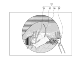
- FIG. 10 is a diagram showing a synthesized image obtained by superimposing a hand model image and an annotation image on an endoscopic image
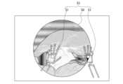
- FIG. 10 is a diagram showing a synthesized image in which an annotation image is superimposed on an endoscopic image
- It is a block diagram which shows an example of a structure of a treatment side apparatus.
- It is a block diagram which shows an example of a structure of the guidance side apparatus.
- FIG. 10 is a diagram showing the functional composition of a support system in a 1st embodiment, and the flow of data.
- FIG. 10 is a diagram showing a synthesized image in which a hand model image is superimposed on an endoscopic image
- FIG. 10 is a diagram showing a synthesized image obtained by superimposing a hand model image and an annotation image on an endoscopic image
- FIG. 10 is a diagram showing a synthesized image in which an annotation
- FIG. 4 is a diagram for explaining a three-dimensional virtual space when generating a three-dimensional hand model image; It is a figure explaining the generation method of a three-dimensional hand model image.
- FIG. 4 is a diagram for explaining a three-dimensional virtual space when generating a three-dimensional hand model image and an annotation image;
- FIG. 4 is a diagram for explaining a method of generating a 3D hand model image and an annotation image;
- FIG. 4 is a diagram for explaining a three-dimensional virtual space when generating a three-dimensional annotation image; It is a figure explaining the generation method of a three-dimensional annotation image.
- FIG. 4 is a diagram for explaining a three-dimensional virtual space when generating a three-dimensional hand model image; It is a figure explaining the generation method of a three-dimensional annotation image.
- FIG. 10 is a diagram showing a composite image obtained by superimposing a hand model image and an annotation image based on 3D image data on a composite image based on treatment-side composite image data;
- FIG. 10 is a diagram illustrating a method of generating a three-dimensional annotation image during parallax adjustment; It is a figure explaining the functional structure of the support system in 2nd Embodiment, and the flow of data.
- FIG. 1 is a diagram for explaining the support system 1.
- FIG. 2 is a diagram showing an endoscopic image 50.
- FIG. 3 is a diagram showing a synthesized image 53 in which a hand model image 51 is superimposed on an endoscopic image 50.
- FIG. 4 is a diagram showing a composite image 54 obtained by superimposing a hand model image 51 and an annotation image 52 on an endoscopic image 50.
- FIG. 5 is a diagram showing a synthesized image 55 in which an annotation image 52 is superimposed on the endoscopic image 50.
- FIG. 1 is a diagram for explaining the support system 1.
- FIG. FIG. 2 is a diagram showing an endoscopic image 50.
- FIG. 3 is a diagram showing a synthesized image 53 in which a hand model image 51 is superimposed on an endoscopic image 50.
- FIG. 4 is a diagram showing a composite image 54 obtained by superimposing a hand model image 51 and an annotation image 52 on an endoscopic image 50.
- FIG. 5 is a diagram showing a synthesized
- the hand model image 51 and the annotation image 52 are actually 3D (three-dimensional) images, they are shown as 2D (two-dimensional) images in FIGS.
- the endoscopic image 50 may be a 3D image or a 2D image, but is shown as a 2D image in FIGS.
- the support system 1 includes a treatment-side device 2 used by a practitioner 4 in an operating room Rm1, and a guidance-side device 3 used by a trainer 6 in a guidance room Rm2 separated from the operating room Rm1. and Therefore, the treatment-side device 2 and the instruction-side device 3 are separated from each other.
- the practitioner 4 is a surgeon of the patient 5, and the instructor 6 is a preceptor who instructs the practitioner 4.
- the practitioner 4 confirms the instruction by the instructor 6.
- An operation can be performed on the patient 5 while
- the treatment-side device 2 includes an endoscope 11 and a 3D monitor 12.
- the instructor device 3 includes a 3D monitor 21 and a 3D position detector 22 .
- the 3D monitor 12 and the 3D monitor 21 are flat panels such as LCD (Liquid Crystal Display), and polarizing filters with different polarization directions are alternately superimposed on odd-numbered lines (horizontal pixel columns) and even-numbered lines. It is a monitor capable of displaying a 3D (three-dimensional) image by a so-called line-by-line method.
- the 3D monitor 12 and the 3D monitor 21 for example, right-rotating circular polarizing filters are superimposed on odd-numbered lines, and left-handed circular polarizing filters are superimposed on even-numbered lines.
- the practitioner 4 wears polarized glasses 7 and views the 3D monitor 12 .
- the polarizing glasses 7 are attached with polarizing filters having different polarizing directions for the right eye side and the left eye side.
- the polarizing glasses 7 have, for example, a right-hand circular polarizing filter attached to the right eye side and a left-hand circular polarizing filter attached to the left eye side.
- the right eye sees only the images of the odd-numbered lines, and the left eye sees only the images of the even-numbered lines.
- the instructor 6 wears the polarizing glasses 7 and views the 3D monitor 21
- the right eye sees only the images of the odd-numbered lines, and the left eye sees only the images of the even-numbered lines. appear.
- the 3D monitor 12 and the 3D monitor 21 show different images (parallax images) to the right and left eyes of the operator 4 and the instructor 6 through the polarizing glasses 7, respectively, so that the 3D image can be viewed. is possible.
- the 3D monitor 12 and the 3D monitor 21 can also show the practitioner 4 and the instructor 6 a 2D image by displaying the same image on the odd-numbered lines and the even-numbered lines.
- the endoscope 11 is inserted into the body cavity of the patient 5 in the treatment-side device 2, for example, so that an endoscope image 50 inside the body cavity as shown in FIG. 2 is displayed on the 3D monitor 12. be.
- the practitioner 4 can confirm the endoscopic image 50 on the 3D monitor 12 .
- the endoscope image 50 may be a 3D image or a 2D image.
- the endoscopic image 50 is also displayed on the 3D monitor 21 of the instruction-side device 3 in the instruction room Rm2.
- the instructor 6 can check the endoscopic image 50 on the 3D monitor 21 while staying in the instruction room Rm2.
- the instruction-side device 3 can three-dimensionally detect the position (coordinates) of the hand of the instructor 6 by means of the three-dimensional position detection unit 22, as will be described later in detail. Based on the position of the hand of the instructor 6 detected by the three-dimensional position detection unit 22, the instructor-side device 3 displays a three-dimensional hand model image 51 imitating the hand of the instructor 6 on the endoscope image 50. indicate. That is, the instruction-side device 3 displays on the 3D monitor 21 a composite image 53 in which the hand model image 51 is superimposed on the endoscopic image 50 as shown in FIG. As a result, the instructor 6 can input instructions while three-dimensionally confirming the movement of his/her own hand with respect to the endoscopic image 50 using the hand model image 51 .
- the instructor-side device 3 it is possible to operate and input instruction contents by a predetermined movement (gesture) of the instructor 6's hand detected by the three-dimensional position detection unit 22. According to the input, the instructor-side device 3 displays an annotation image 52 indicating the content of the instruction (operation input) of the instructor 6 on the endoscopic image 50 .
- the instruction-side device 3 displays on the 3D monitor 21 a composite image 54 in which the hand model image 51 and the annotation image 52 are superimposed on the endoscope image 50 as shown in FIG.
- the instructor 6 can three-dimensionally confirm the contents of his or her instructions for the endoscopic image 50 by means of the annotation image 52 .
- the treatment-side device 2 displays on the 3D monitor 12 a composite image 55 in which an annotation image 52 is superimposed on an endoscopic image 50 as shown in FIG.
- the operator 4 can operate the patient 5 while three-dimensionally confirming the contents of the instruction of the instructor 6 displayed on the 3D monitor 12 .
- FIG. 6 is a block diagram showing an example of the configuration of the treatment-side device 2.
- the treatment-side device 2 includes a CPU (Central Processing Unit) 13, a ROM (Read Only Memory) 14, a RAM (Random Access Memory) 15, a GPU ( This configuration includes a computer having a graphics processing unit) 16 .
- CPU Central Processing Unit
- ROM Read Only Memory
- RAM Random Access Memory
- GPU This configuration includes a computer having a graphics processing unit 16 .
- the CPU 13 executes various processes according to programs stored in the ROM 14 or storage unit 19 .
- the RAM 15 also stores data necessary for the CPU 13 to execute various processes.
- the GPU 16 performs drawing processing (for example, shader processing) using 3D computer graphics according to the drawing command from the CPU 13, and stores the image after the drawing processing in a frame buffer (not shown). The GPU 16 then outputs the image stored in the frame buffer to the 3D monitor 12 .
- drawing processing for example, shader processing
- the CPU 13, ROM 14, RAM 15 and GPU 16 are interconnected via a bus 17.
- An endoscope 11 , a 3D monitor 12 , a communication section 18 and a storage section 19 are also connected to the bus 17 .
- the communication unit 18 performs wired or wireless communication with the instructor device 3 .
- the storage unit 19 is composed of a storage medium such as an HDD (Hard Disk Drive) or an SSD (Solid State Drive). For example, various information can be stored in the storage unit 19 .
- the storage unit 19 can also be used to store program data for the CPU 13 to execute various processes.
- FIG. 7 is a block diagram showing an example of the configuration of the instruction-side device 3.
- the instructor device 3 includes a computer having a CPU 23, a ROM 24, a RAM 25, and a GPU 26 in addition to the 3D monitor 21 and the three-dimensional position detector 22.
- FIG. 7 is a block diagram showing an example of the configuration of the instruction-side device 3.
- the instructor device 3 includes a computer having a CPU 23, a ROM 24, a RAM 25, and a GPU 26 in addition to the 3D monitor 21 and the three-dimensional position detector 22.
- FIG. 7 is a block diagram showing an example of the configuration of the instruction-side device 3.
- the instructor device 3 includes a computer having a CPU 23, a ROM 24, a RAM 25, and a GPU 26 in addition to the 3D monitor 21 and the three-dimensional position detector 22.
- FIG. 7 is a block diagram showing an example of the configuration of the instruction-side device 3.
- the instructor device 3 includes a computer having a CPU 23, a ROM 24, a RAM 25, and
- the CPU 23 executes various processes according to programs stored in the ROM 24 or the storage unit 29 .
- the RAM 25 also stores data necessary for the CPU 23 to execute various processes.
- the GPU 26 performs drawing processing (for example, shader processing) using 3D computer graphics according to drawing commands from the CPU 23, and stores the image after the drawing processing in a frame buffer (not shown). The GPU 26 then outputs the image stored in the frame buffer to the 3D monitor 21 .
- drawing processing for example, shader processing
- the CPU 23, ROM 24, RAM 25 and GPU 26 are interconnected via a bus 27.
- a 3D monitor 21 , a three-dimensional position detection unit 22 , a communication unit 28 and a storage unit 29 are also connected to the bus 27 .
- the communication unit 28 performs wired or wireless communication with the treatment-side device 2 .
- the storage unit 29 is composed of a storage medium such as an HDD or SSD. For example, various information can be stored in the storage unit 29 .
- the storage unit 29 can also be used to store program data for the CPU 23 to execute various processes.
- FIG. 8 is a diagram for explaining the functional configuration and data flow of the support system 1 in the first embodiment.
- the GPU 16 of the treatment-side device 2 functions as an image generator 31 and an image synthesizer 32 .
- the communication unit 18 of the treatment-side device 2 functions as a data transmission unit 33 .
- the communication unit 28 of the instruction-side device 3 functions as a data transmission unit 41. Also, the GPU 26 of the instruction-side device 3 functions as an image generator 42 and an image synthesizer 43 .
- the endoscope 11 has an imaging device, performs predetermined signal processing on the captured image signal obtained by the imaging device, generates an endoscopic image 50, and image data of the endoscopic image 50 (hereinafter referred to as endoscopic image data). (referred to as mirror image data Id) is output to the image synthesizing unit 32 .
- endoscopic image data is a 3D image
- the endoscope 11 has two imaging elements, and the two endoscopic images 50 (parallax image) will be generated.
- the image generating unit 31 generates an annotation image 52 based on the instruction content information CI transmitted from the instruction-side device 3, and the image data of the annotation image 52 (hereinafter referred to as 3D image data Pd1) is sent to the image synthesizing unit. 32.
- the instruction content information CI includes information such as coordinates, line type, color, and line width designated by operation input.
- the image synthesizing unit 32 synthesizes an image based on various types of input image data.
- the image synthesizing unit 32 generates a synthesized image 55 by synthesizing an endoscopic image 50 based on the endoscopic image data Id and an annotation image 52 based on the 3D image data Pd1.
- the image synthesizing unit 32 then outputs the image data of the synthetic image 55 (hereinafter referred to as treatment-side synthetic image data Cd1) to the data transmitting unit 33 and the 3D monitor 12 .
- treatment-side synthetic image data Cd1 the image data of the synthetic image 55
- the image synthesizing unit 32 outputs the endoscope image data Id to the data transmitting unit 33 and the 3D monitor 12 without generating the synthesized image 55 .
- the 3D monitor 12 displays the endoscopic image 50 and the synthesized image 55 .
- the data transmission unit 33 transmits various data to the instructor device 3.
- the data transmission unit 33 transmits the endoscopic image data Id input from the image synthesizing unit 32 and the treatment-side synthetic image data Cd1.
- the three-dimensional position detection unit 22 includes a sensor that three-dimensionally measures the position (coordinates) of the hand of the instructor 6, and is, for example, a Leap Motion Controller manufactured by Ultraleap.
- the three-dimensional position detection unit 22 has an infrared irradiation unit, a stereo infrared camera, and the like. Acquire stereo infrared images.
- the three-dimensional position detection unit 22 performs image analysis on the obtained stereo infrared image to determine the positions of the joints of the hands (fingers, palms, etc.) of the instructor 6 and the tips of the fingers in the three-dimensional space. Positions (hereinafter referred to simply as positions of hands of instructor 6) are detected in three dimensions. Note that the position here is a position indicated by three-dimensional coordinates with reference to a predetermined origin position.
- the three-dimensional position detection unit 22 three-dimensionally detects the instruction content of the instructor 6 based on the position information PI (operation input). For example, when the three-dimensional position detection unit 22 detects a gesture in which the tip of the thumb and the tip of the index finger of the leader 6 are in contact based on the detected position information PI, the tip of the thumb and the tip of the index finger Detects the trajectory of movement while in contact with the device as the instruction content.
- the three-dimensional position detection unit 22 outputs position information PI indicating the detected position of the hand of the instructor 6 to the image generation unit 42, and outputs instruction content information CI indicating the detected instruction content of the instructor 6 to the image generation unit. 42 and the data transmission unit 41 .
- the data transmission unit 41 transmits various data to the treatment-side device 2 .
- the data transmission section 41 transmits the instruction content information CI input from the three-dimensional position detection section 22 .
- the image generation unit 42 generates a hand model image 51 or a hand model image 51 and an annotation image 52 based on the position information PI and the instruction content information CI input from the three-dimensional position detection unit 22, and generates these images.
- Data (hereinafter referred to as 3D image data Pd2) is output to the image synthesizing section 43 .
- the image synthesizing unit 43 synthesizes an image based on various types of input image data. For example, the image synthesizing unit 43 synthesizes the hand model image 51 based on the 3D image data Pd2 or the hand model image 51 and the annotation image 52 with the endoscopic image 50 based on the endoscopic image data Id. Images 53, 54 are generated. Then, the image synthesizing unit 43 outputs image data of the synthesized images 53 and 54 thus generated (hereinafter referred to as instruction-side synthesized image data Cd2) to the 3D monitor 21 . Note that the image composition unit 43 outputs the endoscope image data Id to the 3D monitor 21 without generating the composite images 53 and 54 when the 3D image data Pd2 is not input.
- the 3D monitor 21 displays an endoscope image 50 and synthesized images 53 and 54 .
- the endoscope image data Id obtained by the endoscope 11 is input to the image synthesizing unit 32 of the treatment-side device 2 .
- the image synthesis unit 32 outputs the endoscope image data Id to the 3D monitor 12 and the data transmission unit 33 when the 3D image data Pd1 is not input from the image generation unit 31 .
- the 3D monitor 12 displays an endoscopic image 50 based on the endoscopic image data Id (see FIG. 2). Thereby, the operator 4 can operate while observing the condition inside the body cavity of the patient 5 on the 3D monitor 12 .
- the data transmission unit 33 transmits the endoscopic image data Id input from the image synthesizing unit 32 to the teaching device 3 .
- the image synthesizing unit 43 in the instruction-side device 3 receives the endoscopic image data Id from the treatment-side device 2 (data transmission unit 33).
- the image synthesizing unit 43 outputs the endoscope image data Id to the 3D monitor 21 when the 3D image data Pd2 is not input from the image generating unit 42 .
- the 3D monitor 21 displays an endoscopic image 50 based on the endoscopic image data Id (see FIG. 2).
- the instructor 6 can share the viewpoint with the operator 4 who is in the operating room Rm1 while being in the instruction room Rm2, and can observe the state of the body cavity of the patient 5 and the situation of the operation by the operator 4. be able to.
- the instructor 6 moves his/her hand within the detection range of the 3D position detection unit 22 while confirming the endoscope image 50 on the 3D monitor 21 .
- the three-dimensional position detection unit 22 detects the position of the hand of the instructor 6 and outputs position information PI to the image generation unit 42 .
- the image generation unit 42 When the position information PI is input from the three-dimensional position detection unit 22 to the image generation unit 42, the image generation unit 42 generates a three-dimensional hand model image 51 (see FIG. 3) based on the input position information PI. do.
- FIG. 9 is a diagram for explaining the three-dimensional virtual space when the three-dimensional hand model image 51 is generated.
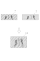
- 10A and 10B are diagrams for explaining a method for generating the three-dimensional hand model image 51.
- FIG. Based on the position information PI input from the three-dimensional position detection unit 22, the image generation unit 42 generates a hand model 63 (polygon ).
- a right-eye virtual camera 61 is arranged at a position corresponding to the right eye
- a left-eye virtual camera 62 is arranged at a position corresponding to the left eye.
- the image generating unit 42 captures the three-dimensional virtual space 60 with the right-eye virtual camera 61 and the left-eye virtual camera 62 to generate a right-eye virtual image 71 and a left-eye virtual image 71 as shown in the upper part of FIG. A virtual image 72 is generated respectively.
- patterns hatchching, dots, etc.
- These patterns are not present in the right-eye virtual image 71 and left-eye virtual image 72 .
- the right-eye virtual image 71 and the left-eye virtual image 72 have the same number of pixels in the horizontal direction as the number of pixels in the 3D monitor 21, and the number of pixels in the vertical direction is half the number of pixels in the 3D monitor 21. ing.
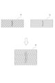
- the image generation unit 42 After generating the right-eye virtual image 71 and the left-eye virtual image 72, the image generation unit 42 generates the right-eye virtual image 71 and the left-eye virtual image 72 for each horizontal line as shown in the lower part of FIG. Alternately arranged hand model images 51 are generated. That is, the image generation unit 42 generates the three-dimensional hand model image 51 by a line-by-line method. The image generator 42 then outputs the 3D image data Pd2 of the hand model image 51 to the image synthesizer 43 .
- the 3D monitor 21 is a monitor capable of displaying a 3D image by a so-called line-by-line method in which different polarizing filters are alternately superimposed on odd-numbered lines and even-numbered lines.
- the instructor 6 wearing the polarizing glasses 7 can see only the right-eye virtual image 71 with the right eye, Only the eye virtual image 72 will be visible to the left eye. Then, the right-eye virtual image 71 and the left-eye virtual image 72 are virtually captured by the right-eye virtual camera 61 and the left-eye virtual camera 62, which are horizontally separated in the three-dimensional virtual space 60, respectively. Since it is a captured image, it is a so-called parallax image.
- the instructor 6 can view the hand model image 51 three-dimensionally by viewing the right-eye virtual image 71 with the right eye and viewing the left-eye virtual image 72 with the left eye.
- the image synthesizing unit 43 adds a hand model based on the 3D image data Pd2 supplied from the image generating unit 42 to the endoscopic image 50 based on the endoscopic image data Id received from the treatment-side device 2 (data transmitting unit 33).
- a composite image 53 is generated by superimposing the image 51 .
- the image synthesizing unit 43 outputs the instruction-side synthetic image data Cd2 of the generated synthetic image 53 to the 3D monitor 21 .
- the synthesized image 53 is displayed on the 3D monitor 21 based on the instruction side synthesized image data Cd2 input from the image synthesizing section 43.
- the instructor 6 can three-dimensionally confirm the position (movement) of his/her hand with respect to the endoscopic image 50 .
- the three-dimensional position detection unit 22 detects the predetermined movement as instruction content.
- the three-dimensional position detection unit 22 then outputs instruction content information CI indicating the detected instruction content to the data transmission unit 41 and the image generation unit 42 .
- the image generation unit 42 receives the position information PI and the instruction content information CI from the three-dimensional position detection unit 22. , a three-dimensional hand model image 51 and annotation image 52 (see FIG. 4) are generated.
- FIG. 11 is a diagram for explaining the three-dimensional virtual space when the three-dimensional hand model image 51 and annotation image 52 are generated.
- 12A and 12B are diagrams for explaining a method of generating the three-dimensional hand model image 51 and the annotation image 52.
- FIG. 9 and 10 are the same, so description thereof will be omitted.
- the image generation unit 42 arranges a hand model 63 in the three-dimensional virtual space 60 based on the position information PI, and creates an instruction content model 64 representing instruction content based on the instruction content information CI. Place (polygon).
- the image generating unit 42 captures the three-dimensional virtual space 60 with the right-eye virtual camera 61 and the left-eye virtual camera 62 to generate a right-eye virtual image 73 and a left-eye virtual image 73 as shown in the upper part of FIG. A virtual image 74 is obtained respectively.
- the image generation unit 42 After generating the right-eye virtual image 73 and the left-eye virtual image 74, the image generation unit 42 generates the right-eye virtual image 73 and the left-eye virtual image 74 for each horizontal line as shown in the lower part of FIG. Alternately arranged hand model images 51 and annotation images 52 are generated. That is, the image generator 42 generates the three-dimensional hand model image 51 and the annotation image 52 in a line-by-line manner. The image generator 42 then outputs the 3D image data Pd2 of the hand model image 51 and the annotation image 52 to the image synthesizer 43 .
- the image synthesizing unit 43 adds a hand model based on the 3D image data Pd2 input from the image generating unit 42 to the endoscopic image 50 based on the endoscopic image data Id received from the treatment-side device 2 (data transmitting unit 33).
- a composite image 54 is generated by superimposing the image 51 and the annotation image 52 .
- the image synthesizing unit 43 outputs the instruction-side synthetic image data Cd2 of the generated synthetic image 54 to the 3D monitor 21 .
- the synthetic image 54 is displayed on the 3D monitor 21 based on the instructor-side synthetic image data Cd2 input from the image synthesizing section 43.
- the instructor 6 can three-dimensionally confirm the instruction content input by a predetermined movement (gesture) of his/her own hand.
- the image generation unit 42 generates the hand model image 51 and the annotation image 52 using shader processing of the GPU 26. Therefore, the instructor device 3 can display the synthesized images 53 and 54 on the 3D monitor 21 at, for example, 60 Hz, and the delay time until the synthesized images 53 and 54 are displayed is extremely short. That is, the synthesized images 53 and 54 are displayed on the 3D monitor 21 with little time lag.
- the instructor 6 can confirm the position of his own hand and the content of instructions (operation input) in three dimensions without feeling a time lag.
- the data transmission unit 41 also transmits the instruction content information CI input from the three-dimensional position detection unit 22 to the treatment-side device 2 .
- instruction content information CI having a smaller communication capacity than the 3D image data Pd2 generated by the image generation unit 42 is transmitted, thereby transmitting data from the guidance-side device 3 to the treatment-side device 2. Reduces communication delays when
- the image generation unit 31 in the treatment-side device 2 receives instruction content information CI from the guidance-side device 3 (data transmission unit 41).
- the image generator 31 generates a three-dimensional annotation image 52 (see FIG. 5) based on the received instruction content information CI.
- FIG. 13 is a diagram for explaining the three-dimensional virtual space when generating the three-dimensional annotation image 52.
- FIG. 14A and 14B are diagrams for explaining a method of generating the three-dimensional annotation image 52.
- FIG. 9 to 12 are the same, description thereof will be omitted.
- the image generator 31 arranges the instruction content model 64 in the three-dimensional virtual space 60 as shown in FIG.
- the image generation unit 31 captures the three-dimensional virtual space 60 with the right-eye virtual camera 61 and the left-eye virtual camera 62 to generate a right-eye virtual image 75 and a left-eye virtual image 75 as shown in the upper part of FIG. A virtual image 76 is obtained respectively.
- the image generation unit 31 After generating the right-eye virtual image 75 and the left-eye virtual image 76, the image generation unit 31 generates the right-eye virtual image 75 and the left-eye virtual image 76 for each horizontal line as shown in the lower part of FIG. Alternating annotation images 52 are generated. That is, the image generation unit 31 generates the three-dimensional annotation image 52 by a line-by-line method. The image generator 31 then outputs the 3D image data Pd1 of the annotation image 52 to the image synthesizer 32 .
- the image synthesizing unit 32 superimposes (synthesizes) an annotation image 52 based on the 3D image data Pd1 input from the image generating unit 31 on the endoscopic image 50 based on the endoscopic image data Id input from the endoscope 11. ) to generate a combined image 55 .
- the image synthesizing unit 32 then outputs treatment-side synthetic image data Cd1 of the generated synthetic image 55 to the 3D monitor 12 and the data transmitting unit 33 .
- the composite image 55 is displayed on the 3D monitor 12 based on the treatment-side composite image data Cd1 input from the image synthesizing section 32.
- the practitioner 4 can three-dimensionally confirm the instruction content of the instructor 6 .
- the image generation unit 31 generates the annotation image 52 using the shader processing of the GPU 16. Therefore, the treatment-side device 2 can display the composite image 55 on the 3D monitor 12 at, for example, 60 Hz, and the delay time until the display of the composite image 55 is extremely short. That is, the synthesized image 55 is displayed on the 3D monitor 12 with little time lag.
- the operator 4 in the operating room Rm1 can operate on the patient 5 while checking the instruction content of the instructor 6 in the guidance room Rm2 on the 3D monitor 12 without feeling a time lag.
- the data transmission unit 33 transmits the treatment-side synthetic image data Cd1 input from the image synthesis unit 32 to the instruction-side device 3.
- FIG. 15 is a diagram showing a composite image 56 in which the hand model image 51 and the annotation image 52 based on the 3D image data Pd2 are superimposed on the composite image 55 based on the treatment-side composite image data Cd1.
- the image synthesizing unit 43 When receiving the treatment-side composite image data Cd1 from the treatment-side device 2 (data transmission unit 33), the image synthesizing unit 43 generates a composite image 55 (endoscopic image) based on the treatment-side composite image data Cd1, as shown in FIG. 50 and the annotation image 52), the hand model image 51 and the annotation image 52 based on the 3D image data Pd2 input from the image generation unit 42 are superimposed to generate a composite image 56.
- the image synthesizing unit 43 outputs the instruction-side synthetic image data Cd2 of the generated synthetic image 56 to the 3D monitor 21 .
- the 3D monitor 21 displays a composite image 56 based on the generated instruction-side composite image data Cd2.
- the instructor 6 can three-dimensionally confirm on the 3D monitor 21 whether or not the annotation images 52 displayed based on the treatment-side combined image data Cd1 and the 3D image data Pd2 are aligned.
- the instructor 6 can confirm the deviation of the annotation image 52 as shown in FIG. 15 on the 3D monitor 21, for example.
- the image generator 42 displays the annotation image 52 based on the 3D image data Pd2 differently from the annotation image 52 based on the treatment-side combined image data Cd1 (3D image data Pd1).
- the composite image 56 may be generated in such a manner that the For example, as shown in FIG. 15, by displaying the annotation image 52 based on the 3D image data Pd2 with a dashed line, the annotation image 52 based on the treatment-side composite image data Cd1 (3D image data Pd1) is displayed (solid line). It can be displayed on the 3D monitor 21 separately.
- displaying and confirming both the annotation image 52 based on the treatment-side combined image data Cd1 (3D image data Pd1) and the annotation image 52 based on the 3D image data Pd2 has the following meaning.
- the instruction content information CI transmitted from the instructor-side device 3 may be partially lost when it is received by the treatment-side device 2 due to factors such as communication failure, or may be set between the devices (2, 3). , and the difference in resolution between the 3D monitors 12 and 21 is not adjusted, and the display coordinates of the annotation image 52 and the like may be misaligned. In this case, an image such as that shown in FIG. 15 may be displayed on the 3D monitor 21 due to the deviation of the display coordinates.
- the image generation unit 31 of the treatment-side apparatus 2 normally generates an annotation image 52 as shown in FIG. 5 based on the received instruction content information CI.
- 3D image data Pd1 in which only a portion of the annotation image 52 is displayed (hereinafter also referred to as missing 3D image data Pd1) is generated due to a partial loss of the instruction content information CI.
- the image synthesizing unit 32 synthesizes the annotation image 52 based on the missing 3D image data Pd1 and the endoscopic image 50 based on the endoscopic image data Id.
- a composite image 55 is generated in which only the parts are superimposed.
- the 3D monitor 12 displays a composite image 55 in which a part of the annotation image 52 is missing.
- the instruction content of the instructor 6 is not accurately reflected on the 3D monitor 12, and the practitioner 4 performs the treatment without grasping all of the instruction content of the instructor 6.
- the instruction-side device 3 synthesizes the composite image 55 based on the treatment-side composite image data Cd1 received from the treatment-side device 2 and the annotation image 52 based on the 3D image data Pd2 input from the image generation unit 42. It will be.
- the annotation image 52 based on the treatment-side combined image data Cd1 (missing 3D image data Pd1) and the annotation image 52 based on the 3D image data Pd2 completely overlap, the instructor 6 There is a possibility that the absence of the annotation image 52 in the display of the 3D monitor 12 cannot be confirmed.
- the image generation unit 42 generates the annotation image 52 displayed with broken lines based on the instruction content information CI.
- the instructor 6 can confirm that the portion of the annotation image 52 displayed only by broken lines is not displayed on the 3D monitor 12 of the treatment-side device 2 .
- the instructor 6 can easily compare the content of his instruction with the content displayed on the 3D monitor 12 viewed by the practitioner 4.
- the instructor 6 can see both the images based on the 3D image data Pd1 and Pd2 by looking at the synthesized image 56 based on the instruction-side synthesized image data Cd2, and the contents of his/her instruction can be transmitted to the operator 4. It is possible to check whether or not the message is transmitted correctly. If the instructor 6 can recognize that the instruction by the image is not correctly transmitted, he/she can take necessary measures.
- a dashed line and a solid line are used for the distinction.
- the display mode is not limited to this as long as the 3D image data Pd1 and Pd2 can be distinguished from each other, and the 3D image data Pd1 and Pd2 can be distinguished by different line types such as line widths, colors, brightness, and the like. Also, it is possible to distinguish by highlighting one of them. It is also conceivable to distinguish and display the portions of the annotation image 52 based on the treatment-side composite image data Cd1 (3D image data Pd1) and the annotation image 52 based on the 3D image data Pd2 that do not match each other.
- the image generation unit 31 and the image generation unit 42 shift the position of the right-eye virtual camera 61 or the left-eye virtual camera 62 in the horizontal direction to capture the three-dimensional hand model image 51 and the annotation image 52 . parallax can be adjusted. For example, when the practitioner 4 inputs a predetermined operation to an operation unit (not shown), the image generation unit 31 moves the right-eye virtual camera 61 and the left-eye virtual camera 62 away from each other. Then, a right-eye virtual image 77 and a left-eye virtual image 78 as shown in the upper part of FIG. 16 are captured. Then, the image generator 31 generates an annotation image 52 as shown in the lower part of FIG. 16 based on the right-eye virtual image 77 and the left-eye virtual image 78 .
- the image generation unit 31 and the image generation unit 42 shift the positions of the right-eye virtual image and the left-eye virtual image in the horizontal direction.
- Parallax adjustment of the annotation image 52 can be performed.
- the hand model image 51 and the annotation image 52 can be three-dimensionally arranged with respect to the endoscopic image 50 at appropriate positions.
- the support system 1 according to the second embodiment differs from the first embodiment in that a hand model image 51 is displayed on the 3D monitor 12 of the treatment-side device 2 .
- FIG. 17 is a diagram for explaining the functional configuration and data flow of the support system 1 in the second embodiment.
- the position information PI is output to the image generator 42 and the data transmitter 41 .
- the data transmission unit 41 transmits the position information PI to the treatment-side apparatus 2 together with the instruction content information CI.
- the image generator 31 of the treatment-side device 2 Upon receiving the position information PI, the image generator 31 of the treatment-side device 2 generates a hand model 63 in the three-dimensional virtual space 60 based on the position information PI, similarly to the image generator 42 in the first embodiment. Place (see FIG. 9).
- the image generating unit 31 captures the three-dimensional virtual space 60 with the right-eye virtual camera 61 and the left-eye virtual camera 62 to generate a right-eye virtual image 71 and a left-eye virtual image 71 as shown in the upper part of FIG. A virtual image 72 is obtained respectively.
- the image generating unit 31 After generating the right-eye virtual image 71 and the left-eye virtual image 72, the image generating unit 31 generates the right-eye virtual image 71 and the left-eye virtual image 72 for each horizontal line as shown in the lower part of FIG. Three-dimensional hand model images 51 arranged alternately are generated. The image generator 31 then outputs the 3D image data Pd1 of the hand model image 51 to the image synthesizer 32 .
- the image synthesizing unit 32 superimposes a hand model image 51 based on the 3D image data Pd1 input from the image generating unit 31 on the endoscopic image 50 based on the endoscopic image data Id input from the endoscope 11.
- a composite image 53 (see FIG. 3) is generated, and treatment-side composite image data Cd1 of the composite image 53 is output to the 3D monitor 12 . Therefore, the 3D monitor 12 displays a composite image 53 based on the treatment-side composite image data Cd1.
- the practitioner 4 can confirm the actual hand position (movement) of the instructor 6 in three dimensions.
- the image generation unit 31 of the treatment-side apparatus 2 upon receiving the position information PI and the instruction content information CI, the image generation unit 31 of the treatment-side apparatus 2 generates the position information PI A hand model 63 is arranged based on , and an instruction content model 64 is arranged based on the instruction content information CI (see FIG. 11).
- the image generating unit 31 captures the three-dimensional virtual space 60 with the right-eye virtual camera 61 and the left-eye virtual camera 62 to generate a right-eye virtual image 73 and a left-eye virtual image 73 as shown in the upper part of FIG. A virtual image 74 is obtained respectively.
- the image generating unit 31 After generating the right-eye virtual image 73 and the left-eye virtual image 74, the image generating unit 31 generates the right-eye virtual image 73 and the left-eye virtual image 74 for each horizontal line as shown in the lower part of FIG. A three-dimensional hand model image 51 and an annotation image 52 arranged alternately are generated. The image generator 31 then outputs the 3D image data Pd1 of the hand model image 51 and the annotation image 52 to the image synthesizer 32 .
- the image synthesizing unit 32 combines an endoscopic image 50 based on the endoscopic image data Id input from the endoscope 11 with a hand model image 51 and an annotation image based on the 3D image data Pd1 input from the image generating unit 31. 52 are superimposed to generate a composite image 54 (see FIG. 4), and treatment-side composite image data Cd1 of the composite image 54 is output to the 3D monitor 12 . Therefore, the 3D monitor 12 displays a composite image 54 based on the treatment-side composite image data Cd1.
- the operator 4 can three-dimensionally confirm the actual hand movements of the instructor 6 in addition to the instruction content of the instructor 6 .
- the support system 1 includes a device to be supported (device 2 on the treatment side) and a support device (device 3 on the instruction side) provided apart from the device to be supported (device 2 on the treatment side).
- the support device (guidance-side device 3) transmits a three-dimensional position detection unit 22 for three-dimensionally detecting the instruction content of the instructor 6, and instruction content information CI indicating the instruction content detected by the three-dimensional position detection unit 22. and a data transmission unit 41 for transmitting data.
- the assisted device (treatment-side device 2) has a first image generation unit (image generation unit 31) that generates a three-dimensional annotation image 52 indicating the instruction content of the instructor 6 based on the transmitted instruction content information CI.
- the annotation image 52 is synthesized with the imaged image (endoscopic image 50) captured by the device to be supported (instructor device 3) to generate a first synthesized image (synthesized image 55). section (image synthesizing section 32).
- the treatment-side device 2 can display a composite image 55 in which the three-dimensional annotation image 52 is superimposed on the endoscopic image 50 on the 3D monitor 12 . Therefore, the practitioner 4 viewing the 3D monitor 12 through the polarizing glasses 7 visually recognizes the three-dimensional annotation image 52, and thus can view the instruction content of the instructor 6 three-dimensionally (in addition to the plane direction, the depth direction). information) can be verified. In other words, the support system 1 can more accurately recognize the instruction content of the instructor 6 .
- the three-dimensional position detection unit 22 detects the position of the hand of the instructor 6 in three dimensions.
- the support device instructor-side device 3 generates a second image that generates a three-dimensional hand model image 51 based on the position information PI indicating the position of the hand of the instructor 6 detected by the three-dimensional position detection unit 22.
- unit image generating unit 42 synthesizes the hand model image 51 with the captured image (endoscopic image 50) transmitted from the device to be assisted (treatment-side device 2) to create a second synthesized image (synthesized image 53). and a second image synthesizing unit (image synthesizing unit 43) that generates the .
- the instructor 6 viewing the 3D monitor 21 through the polarizing glasses 7 can three-dimensionally confirm the position of his or her own hand with respect to the endoscopic image 50 .
- the second image generation unit (image generation unit 42) generates the three-dimensional hand model image 51 and the annotation image 52 based on the position information PI and the instruction content information CI.
- the unit 43) synthesizes the hand model image 51 and the annotation image 52 with the captured image (endoscopic image 50) to generate a third synthesized image (synthesized image 54).
- the instructor 6 viewing the 3D monitor 21 through the polarizing glasses 7 can three-dimensionally confirm the position of his/her own hand and the content of the instructions with respect to the endoscopic image 50 .
- the first image generation unit uses shader processing of the GPU 16 to generate a right-eye annotation image (right-eye virtual image 75) and a left-eye annotation image (left eye image) based on the instruction content information CI.
- the annotation image 52 is generated by synthesizing the annotation image for the right eye and the annotation image for the left eye in a line-by-line manner. As a result, the treatment-side device 2 can extremely shorten the delay time until the composite image 55 is displayed on the 3D monitor 12, and display can be performed with little time lag.
- the first image generation unit shifts the horizontal positions of the right-eye annotation image (right-eye virtual image 75) and the left-eye annotation image (left-eye virtual image 76), Parallax adjustment of the three-dimensional annotation image 52 is performed.
- the treatment-side device 2 adjusts the parallax so that the depth direction of the annotation image 52 with respect to the endoscopic image 50 is corrected. Position can be adjusted.
- the treatment-side device 2 can more accurately recognize the instruction content of the instructor 6 .
- the support system 1 a surgery support system has been described in which the practitioner 4 can perform surgery on the patient 5 while receiving instructions from the instructor 6 who is in a remote location.
- the system 1 can be widely applied to situations in which the instructor 6 at a remote location gives instructions to the operator 4 while visually recognizing the captured image on the operator's side.
- the support system 1 can be applied to various uses such as athletes and coaches in sports guidance, instructors and students in learning support such as education and vocational training, and presenters and listeners in remote conferences.
- the three-dimensional position detection unit 22 in FIG. may be detected by other equipment as long as it can be detected in three dimensions.
- the GPU 16 functions as the image generator 31 and the image synthesizer 32, but the CPU 13 may function as the image generator 31 and the image synthesizer 32. and the GPU 16 may share the functions of the image generating unit 31 and the image synthesizing unit 32 .
- the GPU 26 functions as the image generator 42 and the image synthesizer 43, but the CPU 23 may function as the image generator 42 and the image synthesizer 43. and the GPU 26 may share the functions of the image generating unit 42 and the image synthesizing unit 43 .
- the 3D images displayed on the 3D monitor 12 and the 3D monitor 21 are generated by a line-by-line method, but may be generated by another method. That is, any method may be used as long as at least the hand model image 51 and the annotation image 52 are displayed three-dimensionally on the 3D monitors 12 and 21 .
Landscapes
- Engineering & Computer Science (AREA)
- Physics & Mathematics (AREA)
- General Physics & Mathematics (AREA)
- Theoretical Computer Science (AREA)
- Health & Medical Sciences (AREA)
- Educational Technology (AREA)
- Nuclear Medicine, Radiotherapy & Molecular Imaging (AREA)
- Radiology & Medical Imaging (AREA)
- Medical Informatics (AREA)
- Educational Administration (AREA)
- Surgery (AREA)
- Life Sciences & Earth Sciences (AREA)
- Business, Economics & Management (AREA)
- General Health & Medical Sciences (AREA)
- Software Systems (AREA)
- Computer Vision & Pattern Recognition (AREA)
- Geometry (AREA)
- Computer Graphics (AREA)
- Gynecology & Obstetrics (AREA)
- Algebra (AREA)
- Animal Behavior & Ethology (AREA)
- Heart & Thoracic Surgery (AREA)
- Public Health (AREA)
- Veterinary Medicine (AREA)
- Pulmonology (AREA)
- Chemical & Material Sciences (AREA)
- Medicinal Chemistry (AREA)
- Molecular Biology (AREA)
- Computational Mathematics (AREA)
- Mathematical Analysis (AREA)
- Mathematical Optimization (AREA)
- Mathematical Physics (AREA)
- Pure & Applied Mathematics (AREA)
- Biomedical Technology (AREA)
- Pathology (AREA)
- Oral & Maxillofacial Surgery (AREA)
- Endoscopes (AREA)
Abstract
Description
本発明は上記事情に鑑みてなされたものであり、遠隔地にいる指導者が施術者に適切な支援を行えるような支援システムを提供することを目的とする。
[1-1.支援システムの概要]
図1は、支援システム1を説明する図である。図2は、内視鏡画像50を示す図である。図3は、内視鏡画像50に手モデル画像51を重畳した合成画像53を示す図である。図4は、内視鏡画像50に手モデル画像51およびアノテーション画像52を重畳した合成画像54を示す図である。図5は、内視鏡画像50にアノテーション画像52を重畳した合成画像55を示す図である。
なお、手モデル画像51およびアノテーション画像52は、実際には3D(3次元)画像であるが、図3~図5では2D(2次元)画像として示している。また、内視鏡画像50は、3D画像であっても2D画像であってもよいが、図2~図5では2D画像として示している。
なお、3Dモニタ12および3Dモニタ21は、例えば、奇数列のラインに右回転円偏光フィルタが重ねられ、偶数列のラインに左回転円偏光フィルタが重ねられている。
同様に、指導者6は、偏光メガネ7を装着して3Dモニタ21を視認したときに、右眼には奇数列のラインの画像だけが見え、左眼には偶数列のラインの画像だけが見える。
すなわち、指導側装置3では、図3に示すような内視鏡画像50に手モデル画像51が重畳された合成画像53を3Dモニタ21に表示する。
これにより、指導者6は、内視鏡画像50に対する自身の手の動きを手モデル画像51によって3次元で確認しながら、指示内容を入力することができる。
これにより、指導者6は、内視鏡画像50に対する自身の指示内容をアノテーション画像52によって3次元で確認することができる。
これにより、施術者4は、3Dモニタ12に表示された指導者6の指示内容を3次元で確認しながら患者5に対する施術を行うことができる。
図6は、施術側装置2の構成の一例を示すブロック図である。図6に示すように、施術側装置2は、内視鏡11および3Dモニタ12に加え、CPU(Central Processing Unit)13、ROM(Read Only Memory)14、RAM(Random Access Memory)15、GPU(Graphics Processing Unit)16を備えるコンピュータを含んだ構成である。
ここで指示内容情報CIは、操作入力で指定された座標、線種、色彩、線幅などの情報を含んでいる。
そして、画像合成部32は、合成画像55の画像データ(以下、施術側合成画像データCd1と表記する)をデータ送信部33および3Dモニタ12に出力する。
なお、画像合成部32は、3D画像データPd1が入力されていない場合、合成画像55を生成することなく、内視鏡画像データIdをデータ送信部33および3Dモニタ12に出力する。
なお、画像合成部43は、3D画像データPd2が入力されていない場合、合成画像53、54を生成することなく、内視鏡画像データIdを3Dモニタ21に出力する。
第1の実施形態における支援システム1の詳細について図8を参照して説明する。
まず、施術側装置2は、内視鏡11により得られた内視鏡画像データIdが画像合成部32に入力される。
画像合成部43は、3D画像データPd2が画像生成部42から入力されていない場合、内視鏡画像データIdを3Dモニタ21に出力する。
画像生成部42は、3次元位置検出部22から入力された位置情報PIに基づいて、図9に示すように、3次元仮想空間60上に指導者6の手を模した手モデル63(ポリゴン)を配置する。また、3次元仮想空間60には、右眼に対応する位置に右眼用仮想カメラ61を配置するとともに、左眼に対応する位置に左眼用仮想カメラ62を配置する。
そして、画像生成部42は、手モデル画像51の3D画像データPd2を画像合成部43に出力する。
そして、画像生成部42は、手モデル画像51およびアノテーション画像52の3D画像データPd2を画像合成部43に出力する。
そして、画像生成部31は、アノテーション画像52の3D画像データPd1を画像合成部32に出力する。
ずれが生じた場合、指導者6は、例えば図15で示すようなアノテーション画像52のずれを3Dモニタ21上で確認することができる。
例えば、図15に示すように、3D画像データPd2に基づくアノテーション画像52を破線で表示させることで、施術側合成画像データCd1(3D画像データPd1)に基づくアノテーション画像52の表示(実線)と区別して3Dモニタ21上に表示させることができる。
この場合、3Dモニタ21には表示座標のずれにより図15のような画像が表示されることがある。
指導者6が施術者4側の3Dモニタ12の表示状況を確認するためには、3D画像データPd1、Pd2に基づく画像を異なる態様で表示させることが望ましい。
これにより、指導者6は、破線のみで表示されたアノテーション画像52の部分が、施術側装置2の3Dモニタ12に表示されていないことを確認することができる。
つまり、指導者6は、3Dモニタ21上で、自身の指示内容と、施術者4の見ている3Dモニタ12の表示内容を容易に比較できる。
また、施術側合成画像データCd1(3D画像データPd1)に基づくアノテーション画像52と、3D画像データPd2に基づくアノテーション画像52との一致しない部分を区別して表示することも考えられる。
例えば、画像生成部31は、施術者4によって操作部(不図示)に対して所定の操作が入力されると、右眼用仮想カメラ61と左眼用仮想カメラ62とを離隔するように移動させ、図16上段に示すような右眼仮想画像77および左眼仮想画像78を撮像する。そして、画像生成部31は、右眼仮想画像77および左眼仮想画像78に基づいて、図16下段に示すようなアノテーション画像52を生成する。
これにより、内視鏡画像50に対する手モデル画像51およびアノテーション画像52を3次元的に適切な位置に配置することができる。
次に、第2の実施形態について説明する。第2の実施形態における支援システム1では、施術側装置2の3Dモニタ12に手モデル画像51を表示する点で、第1の実施形態と異なる。
上述したように、支援システム1は、被支援装置(施術側装置2)と、被支援装置(施術側装置2)とは離隔して設けられる支援装置(指導側装置3)とを備える。
支援装置(指導側装置3)は、指導者6の指示内容を3次元で検出する3次元位置検出部22と、3次元位置検出部22により検出された指示内容を示す指示内容情報CIを送信するデータ送信部41とを備える。
被支援装置(施術側装置2)は、送信された指示内容情報CIに基づいて、指導者6の指示内容を示す3次元のアノテーション画像52を生成する第1画像生成部(画像生成部31)と、被支援装置(指導側装置3)により撮像された撮像画像(内視鏡画像50)に対してアノテーション画像52を合成して第1合成画像(合成画像55)を生成する第1画像合成部(画像合成部32)と、を備える。
したがって、偏光メガネ7を介して3Dモニタ12を視認する施術者4は、3次元のアノテーション画像52を視認することにより、指導者6の指示内容を3次元で(平面方向に加えて奥行方向の情報を含めて)確認することができる。すなわち、支援システム1では、指導者6の指示内容をより正確に認識することができる。
これにより、偏光メガネ7を介して3Dモニタ21を視認する指導者6は、内視鏡画像50に対する自身の手の位置を3次元で確認することができる。
これにより、偏光メガネ7を介して3Dモニタ21を視認する指導者6は、内視鏡画像50に対する自身の手の位置および指示内容を3次元で確認することができる。
これにより、施術側装置2では、合成画像55を3Dモニタ12に表示するまでの遅延時間が極めて短くすることができ、タイムラグの少ない表示を行うことができる。
これにより、施術側装置2では、内視鏡画像50に対してアノテーション画像52の奥行方向がずれて見える場合に、視差調整を行うことで、内視鏡画像50に対するアノテーション画像52の奥行方向の位置を調整することができる。かくして、施術側装置2では、指導者6の指示内容をより正確に認識することができる。
なお、本実施形態では、支援システム1の一例として、施術者4が遠隔地にいる指導者6の指示を受けながら患者5に対して施術を行うことのできる手術支援システムについて説明したが、支援システム1は、遠隔地にいる指導者6が、施術側の撮像画像を視認しながら施術者4に対して指示を行う状況に幅広く適用することが可能である。
例えば、スポーツ指導における選手と監督、教育や職業訓練などの学習支援における講師と受講者、リモート会議における発表者と傍聴者など、様々な用途に支援システム1を適用できる。
2 施術側装置
3 指導側装置
11 内視鏡
12 3Dモニタ
16 GPU
21 3Dモニタ
22 3次元位置検出部
26 GPU
31 画像生成部
32 画像合成部
33 データ送信部
41 データ送信部
42 画像生成部
43 画像合成部
Claims (7)
- 被支援装置と、前記被支援装置とは離隔して設けられる支援装置とを備える支援システムであって、
前記支援装置は、
指導者の指示内容を3次元で検出する3次元位置検出部と、
前記3次元位置検出部により検出された指示内容を示す指示内容情報を送信するデータ送信部と、を備え、
前記被支援装置は、
送信された前記指示内容情報に基づいて、前記指導者の指示内容を示す3次元のアノテーション画像を生成する第1画像生成部と、
前記被支援装置により撮像された撮像画像に対して前記アノテーション画像を合成して第1合成画像を生成する第1画像合成部と、を備える
支援システム。 - 前記3次元位置検出部は、前記指導者の手の位置を3次元で検出し、
前記支援装置は、
前記3次元位置検出部により検出された前記指導者の手の位置を示す位置情報に基づいて、3次元の手モデル画像を生成する第2画像生成部と、
前記被支援装置から送信された前記撮像画像に、前記手モデル画像を合成して第2合成画像を生成する第2画像合成部と、を備える
請求項1に記載の支援システム。 - 前記第2画像生成部は、前記位置情報および前記指示内容情報に基づいて、前記手モデル画像および前記アノテーション画像を生成し、
前記第2画像合成部は、前記撮像画像に前記手モデル画像および前記アノテーション画像を合成して第3合成画像を生成する
請求項2に記載の支援システム。 - 前記第1画像生成部は、
GPUのシェーダー処理を用いて、前記指示内容情報に基づいて右眼用アノテーション画像および左眼用アノテーション画像を生成し、前記右眼用アノテーション画像および前記左眼用アノテーション画像をラインバイライン方式で合成することにより前記アノテーション画像を生成する
請求項1に記載の支援システム。 - 前記第1画像生成部は、
前記右眼用アノテーション画像および前記左眼用アノテーション画像の水平方向の位置をずらすことにより、前記アノテーション画像の視差調整を行う
請求項4に記載の支援システム。 - 被支援装置に離隔して設けられる支援装置であって、
指導者の指示内容を3次元で検出する3次元位置検出部と、
前記3次元位置検出部により検出された指示内容を示す指示内容情報を送信するデータ送信部と、
を備える支援装置。 - 支援装置に離隔して設けられる被支援装置であって、
前記支援装置において3次元で検出された指導者の指示内容を示す指示内容情報に基づいて、前記指導者の指示内容を示す3次元のアノテーション画像を生成する第1画像生成部と、
前記被支援装置により撮像された撮像画像に対して前記アノテーション画像を合成して第1合成画像を生成する第1画像合成部と、
を備える被支援装置。
Priority Applications (5)
| Application Number | Priority Date | Filing Date | Title |
|---|---|---|---|
| CN202280077469.8A CN118284382A (zh) | 2022-02-09 | 2022-02-09 | 辅助系统、辅助装置、被辅助装置 |
| PCT/JP2022/005122 WO2023152829A1 (ja) | 2022-02-09 | 2022-02-09 | 支援システム、支援装置、被支援装置 |
| EP22925850.4A EP4470496A4 (en) | 2022-02-09 | 2022-02-09 | ASSISTANCE SYSTEM, ASSISTANCE DEVICE AND ASSISTED DEVICE |
| JP2023543415A JP7401157B1 (ja) | 2022-02-09 | 2022-02-09 | 支援システム、支援装置、被支援装置 |
| US18/773,703 US20240371063A1 (en) | 2022-02-09 | 2024-07-16 | Assistance system, assistance device, and assisted device |
Applications Claiming Priority (1)
| Application Number | Priority Date | Filing Date | Title |
|---|---|---|---|
| PCT/JP2022/005122 WO2023152829A1 (ja) | 2022-02-09 | 2022-02-09 | 支援システム、支援装置、被支援装置 |
Related Child Applications (1)
| Application Number | Title | Priority Date | Filing Date |
|---|---|---|---|
| US18/773,703 Continuation US20240371063A1 (en) | 2022-02-09 | 2024-07-16 | Assistance system, assistance device, and assisted device |
Publications (1)
| Publication Number | Publication Date |
|---|---|
| WO2023152829A1 true WO2023152829A1 (ja) | 2023-08-17 |
Family
ID=87563818
Family Applications (1)
| Application Number | Title | Priority Date | Filing Date |
|---|---|---|---|
| PCT/JP2022/005122 Ceased WO2023152829A1 (ja) | 2022-02-09 | 2022-02-09 | 支援システム、支援装置、被支援装置 |
Country Status (5)
| Country | Link |
|---|---|
| US (1) | US20240371063A1 (ja) |
| EP (1) | EP4470496A4 (ja) |
| JP (1) | JP7401157B1 (ja) |
| CN (1) | CN118284382A (ja) |
| WO (1) | WO2023152829A1 (ja) |
Families Citing this family (1)
| Publication number | Priority date | Publication date | Assignee | Title |
|---|---|---|---|---|
| US20250235941A1 (en) * | 2024-01-24 | 2025-07-24 | Textron Aviation Inc. | Bandsaw Cutting System |
Citations (4)
| Publication number | Priority date | Publication date | Assignee | Title |
|---|---|---|---|---|
| JP2000271147A (ja) | 1999-03-19 | 2000-10-03 | Olympus Optical Co Ltd | 遠隔手術支援システム |
| WO2019083805A1 (en) * | 2017-10-23 | 2019-05-02 | Intuitive Surgical Operations, Inc. | SYSTEMS AND METHODS FOR PRESENTING ENHANCED REALITY ON A SCREEN OF A TELEOPERATION SYSTEM |
| JP2019162339A (ja) * | 2018-03-20 | 2019-09-26 | ソニー株式会社 | 手術支援システムおよび表示方法 |
| WO2020090943A1 (ja) * | 2018-10-30 | 2020-05-07 | Cyberdyne株式会社 | インタラクティブ情報伝達システム及びインタラクティブ情報伝達方法並びに情報伝達システム |
Family Cites Families (2)
| Publication number | Priority date | Publication date | Assignee | Title |
|---|---|---|---|---|
| US9503681B1 (en) * | 2015-05-29 | 2016-11-22 | Purdue Research Foundation | Simulated transparent display with augmented reality for remote collaboration |
| US20230105111A1 (en) * | 2020-03-06 | 2023-04-06 | Universität Heidelberg | System and Method for Teaching Minimally Invasive Interventions |
-
2022
- 2022-02-09 EP EP22925850.4A patent/EP4470496A4/en active Pending
- 2022-02-09 CN CN202280077469.8A patent/CN118284382A/zh active Pending
- 2022-02-09 JP JP2023543415A patent/JP7401157B1/ja active Active
- 2022-02-09 WO PCT/JP2022/005122 patent/WO2023152829A1/ja not_active Ceased
-
2024
- 2024-07-16 US US18/773,703 patent/US20240371063A1/en active Pending
Patent Citations (4)
| Publication number | Priority date | Publication date | Assignee | Title |
|---|---|---|---|---|
| JP2000271147A (ja) | 1999-03-19 | 2000-10-03 | Olympus Optical Co Ltd | 遠隔手術支援システム |
| WO2019083805A1 (en) * | 2017-10-23 | 2019-05-02 | Intuitive Surgical Operations, Inc. | SYSTEMS AND METHODS FOR PRESENTING ENHANCED REALITY ON A SCREEN OF A TELEOPERATION SYSTEM |
| JP2019162339A (ja) * | 2018-03-20 | 2019-09-26 | ソニー株式会社 | 手術支援システムおよび表示方法 |
| WO2020090943A1 (ja) * | 2018-10-30 | 2020-05-07 | Cyberdyne株式会社 | インタラクティブ情報伝達システム及びインタラクティブ情報伝達方法並びに情報伝達システム |
Non-Patent Citations (1)
| Title |
|---|
| See also references of EP4470496A4 |
Also Published As
| Publication number | Publication date |
|---|---|
| US20240371063A1 (en) | 2024-11-07 |
| JP7401157B1 (ja) | 2023-12-19 |
| JPWO2023152829A1 (ja) | 2023-08-17 |
| EP4470496A1 (en) | 2024-12-04 |
| EP4470496A4 (en) | 2025-03-19 |
| CN118284382A (zh) | 2024-07-02 |
Similar Documents
| Publication | Publication Date | Title |
|---|---|---|
| US10622111B2 (en) | System and method for image registration of multiple video streams | |
| US8911358B2 (en) | Endoscopic vision system | |
| JP3717653B2 (ja) | 頭部搭載型画像表示装置 | |
| US9092996B2 (en) | Microsurgery simulator | |
| US8520024B2 (en) | Virtual interactive presence systems and methods | |
| JP2026004518A (ja) | 外科手術仮想現実ユーザインターフェース | |
| JP7373800B2 (ja) | キャリブレーションシステム、及び、瞳孔間のキャリブレーション方法 | |
| KR20080089376A (ko) | 3차원 텔레스트레이션을 제공하는 의료용 로봇 시스템 | |
| KR101447931B1 (ko) | 증강현실을 이용한 수술 로봇 시스템 및 그 제어 방법 | |
| US20240371063A1 (en) | Assistance system, assistance device, and assisted device | |
| CN104887314A (zh) | 用于立体内窥镜手术导航的虚拟立体内窥镜显示方法及设备 | |
| CN115919239A (zh) | 用于3d内窥镜成像系统的成像方法和3d内窥镜成像系统 | |
| JP7156751B1 (ja) | 情報処理装置、支援システム | |
| JP7393842B1 (ja) | 支援システム、支援装置、被支援装置 | |
| US9848758B2 (en) | Stereoscopic endoscope system | |
| KR20150007517A (ko) | 실감형 시각정보를 이용한 수술동작 지시방법 | |
| WO2024202956A1 (ja) | 医療用データ処理装置、医療用システム | |
| Guana | Three-Dimensional Minimally Invasive Surgery Enhances Surgeon’s Performances, Reducing Operative Time and Errors. Comparative Study in a Pediatric Surgery Setting. | |
| NZ621149B2 (en) | System and method for image registration of multiple video streams |
Legal Events
| Date | Code | Title | Description |
|---|---|---|---|
| WWE | Wipo information: entry into national phase |
Ref document number: 2023543415 Country of ref document: JP |
|
| 121 | Ep: the epo has been informed by wipo that ep was designated in this application |
Ref document number: 22925850 Country of ref document: EP Kind code of ref document: A1 |
|
| WWE | Wipo information: entry into national phase |
Ref document number: 202280077469.8 Country of ref document: CN |
|
| ENP | Entry into the national phase |
Ref document number: 2022925850 Country of ref document: EP Effective date: 20240827 |
|
| NENP | Non-entry into the national phase |
Ref country code: DE |