WO2023153365A1 - 内燃機関の制御装置及びその制御方法 - Google Patents
内燃機関の制御装置及びその制御方法 Download PDFInfo
- Publication number
- WO2023153365A1 WO2023153365A1 PCT/JP2023/003800 JP2023003800W WO2023153365A1 WO 2023153365 A1 WO2023153365 A1 WO 2023153365A1 JP 2023003800 W JP2023003800 W JP 2023003800W WO 2023153365 A1 WO2023153365 A1 WO 2023153365A1
- Authority
- WO
- WIPO (PCT)
- Prior art keywords
- air
- fuel ratio
- internal combustion
- combustion engine
- fuel
- Prior art date
- Legal status (The legal status is an assumption and is not a legal conclusion. Google has not performed a legal analysis and makes no representation as to the accuracy of the status listed.)
- Ceased
Links
Images


Classifications
-
- F—MECHANICAL ENGINEERING; LIGHTING; HEATING; WEAPONS; BLASTING
- F02—COMBUSTION ENGINES; HOT-GAS OR COMBUSTION-PRODUCT ENGINE PLANTS
- F02D—CONTROLLING COMBUSTION ENGINES
- F02D41/00—Electrical control of supply of combustible mixture or its constituents
- F02D41/02—Circuit arrangements for generating control signals
- F02D41/04—Introducing corrections for particular operating conditions
- F02D41/12—Introducing corrections for particular operating conditions for deceleration
- F02D41/123—Introducing corrections for particular operating conditions for deceleration the fuel injection being cut-off
- F02D41/126—Introducing corrections for particular operating conditions for deceleration the fuel injection being cut-off transitional corrections at the end of the cut-off period
-
- F—MECHANICAL ENGINEERING; LIGHTING; HEATING; WEAPONS; BLASTING
- F02—COMBUSTION ENGINES; HOT-GAS OR COMBUSTION-PRODUCT ENGINE PLANTS
- F02D—CONTROLLING COMBUSTION ENGINES
- F02D41/00—Electrical control of supply of combustible mixture or its constituents
- F02D41/02—Circuit arrangements for generating control signals
- F02D41/14—Introducing closed-loop corrections
- F02D41/1438—Introducing closed-loop corrections using means for determining characteristics of the combustion gases; Sensors therefor
- F02D41/1444—Introducing closed-loop corrections using means for determining characteristics of the combustion gases; Sensors therefor characterised by the characteristics of the combustion gases
- F02D41/1454—Introducing closed-loop corrections using means for determining characteristics of the combustion gases; Sensors therefor characterised by the characteristics of the combustion gases the characteristics being an oxygen content or concentration or the air-fuel ratio
-
- F—MECHANICAL ENGINEERING; LIGHTING; HEATING; WEAPONS; BLASTING
- F02—COMBUSTION ENGINES; HOT-GAS OR COMBUSTION-PRODUCT ENGINE PLANTS
- F02D—CONTROLLING COMBUSTION ENGINES
- F02D41/00—Electrical control of supply of combustible mixture or its constituents
- F02D41/02—Circuit arrangements for generating control signals
- F02D41/04—Introducing corrections for particular operating conditions
- F02D41/06—Introducing corrections for particular operating conditions for engine starting or warming up
- F02D41/062—Introducing corrections for particular operating conditions for engine starting or warming up for starting
- F02D41/065—Introducing corrections for particular operating conditions for engine starting or warming up for starting at hot start or restart
-
- F—MECHANICAL ENGINEERING; LIGHTING; HEATING; WEAPONS; BLASTING
- F02—COMBUSTION ENGINES; HOT-GAS OR COMBUSTION-PRODUCT ENGINE PLANTS
- F02D—CONTROLLING COMBUSTION ENGINES
- F02D41/00—Electrical control of supply of combustible mixture or its constituents
- F02D41/30—Controlling fuel injection
- F02D41/38—Controlling fuel injection of the high pressure type
-
- F—MECHANICAL ENGINEERING; LIGHTING; HEATING; WEAPONS; BLASTING
- F02—COMBUSTION ENGINES; HOT-GAS OR COMBUSTION-PRODUCT ENGINE PLANTS
- F02D—CONTROLLING COMBUSTION ENGINES
- F02D41/00—Electrical control of supply of combustible mixture or its constituents
- F02D41/30—Controlling fuel injection
- F02D41/32—Controlling fuel injection of the low pressure type
- F02D41/34—Controlling fuel injection of the low pressure type with means for controlling injection timing or duration
- F02D41/345—Controlling injection timing
-
- Y—GENERAL TAGGING OF NEW TECHNOLOGICAL DEVELOPMENTS; GENERAL TAGGING OF CROSS-SECTIONAL TECHNOLOGIES SPANNING OVER SEVERAL SECTIONS OF THE IPC; TECHNICAL SUBJECTS COVERED BY FORMER USPC CROSS-REFERENCE ART COLLECTIONS [XRACs] AND DIGESTS
- Y02—TECHNOLOGIES OR APPLICATIONS FOR MITIGATION OR ADAPTATION AGAINST CLIMATE CHANGE
- Y02T—CLIMATE CHANGE MITIGATION TECHNOLOGIES RELATED TO TRANSPORTATION
- Y02T10/00—Road transport of goods or passengers
- Y02T10/10—Internal combustion engine [ICE] based vehicles
- Y02T10/40—Engine management systems
Definitions
- the present invention relates to a control device and control method for an internal combustion engine, and more particularly to improvement of air-fuel ratio control during fuel cut recovery.
- Patent Literature 1 describes an air-fuel ratio control method and an air-fuel ratio control device for an internal combustion engine that cuts fuel during vehicle deceleration and stops air-fuel ratio feedback control.
- this patent document 1 when the air-fuel ratio reaches within a predetermined range near the target air-fuel ratio after the resumption of fuel supply and the end of the fuel increase, or when the duration of open loop control reaches a predetermined upper limit time, the air-fuel ratio is reduced. Fuel ratio feedback control is restarted.
- the restart of air-fuel ratio feedback control is determined based on the target air-fuel ratio, the restart of feedback control will be delayed if there is a temporary deviation in the air-fuel ratio due to manufacturing variations in parts or injector failure. During this delay period, emissions can deteriorate. Also, if determined by the duration of open-loop control, emissions may deteriorate until the predetermined upper limit time is reached.
- the present invention has been made in view of the circumstances as described above, and its object is to provide a control device and control method for an internal combustion engine that can suppress deterioration of emissions during fuel cut recovery.
- a control device for an internal combustion engine that performs feedback control of an air-fuel ratio of an internal combustion engine, wherein the control device controls the air-fuel ratio feedback when restarting combustion after fuel cut of the internal combustion engine. is stopped, an air-fuel ratio criterion is set according to the rich-side peak value of the air-fuel ratio after the start of the fuel increase, and after the fuel is increased, the set air-fuel ratio
- a controller for an internal combustion engine is provided that is configured to initiate said air-fuel ratio feedback when a criterion is met.
- a control method for an internal combustion engine that performs feedback control of an air-fuel ratio of the internal combustion engine, the control method comprising: cutting fuel supply to the internal combustion engine; After cutting off the supply of fuel, when starting combustion in the internal combustion engine again, increasing the amount of fuel in a state where the air-fuel ratio feedback is stopped and supplying it to the internal combustion engine; setting an air-fuel ratio criterion according to the rich side peak value of the fuel, and starting control of the internal combustion engine by the air-fuel ratio feedback when the set air-fuel ratio criterion is reached after the fuel is increased. and a control method for an internal combustion engine.
- the air-fuel ratio feedback control after fuel cut recovery is performed within a predetermined timeout period. It can be restarted at an appropriate early timing without waiting for progress. Therefore, according to the present invention, it is possible to provide a control device and control method for an internal combustion engine that can suppress deterioration of emissions during fuel cut recovery.
- FIG. 1 is a schematic configuration diagram for explaining a control device for an internal combustion engine according to an embodiment of the invention
- FIG. 2 is a functional block diagram showing an extracted main part of the control device shown in FIG. 1
- FIG. 1 is a flowchart showing a control determination operation for explaining a control method for an internal combustion engine according to an embodiment of the present invention
- FIG. 4 is a control method following FIG. 3 and is a flowchart showing a criteria calculation operation
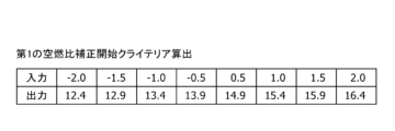
- FIG. FIG. 5 is a diagram for explaining calculation of a first air-fuel ratio correction start criterion in FIG. 4
- FIG. 5 is a diagram for explaining calculation of a second air-fuel ratio correction start criterion in FIG. 4
- FIG. 10 is a waveform chart showing a method of determining whether the air-fuel ratio is rich or lean, and is a waveform diagram in the case where the air-fuel ratio is not delayed due to the air-fuel ratio being deviated.
- FIG. 4 is a waveform diagram showing a method of determining whether the air-fuel ratio is rich or lean, and is a waveform diagram when the air-fuel ratio is deviated and there is a response delay in the air-fuel ratio.
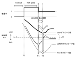
- FIG. 4 is a waveform diagram showing criteria for resuming air-fuel ratio feedback according to the state of air-fuel ratio deviation, and in the case where the air-fuel ratio is deviated and there is no air-fuel ratio response delay.
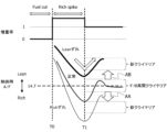
- FIG. 5 is a waveform diagram showing criteria for resuming air-fuel ratio feedback according to the state of air-fuel ratio deviation, and in the case where the air-fuel ratio is deviated and there is a response delay in the air-fuel ratio.
- FIG. 5 is a flow chart showing the operation of calculating the feedback correction amount, which is the control method continued from FIG. 4 .
- FIG. 11 is a diagram for explaining calculation of an air-fuel ratio correction start criterion in FIG.
- 4 is a timing chart for explaining calculation of A/F deviation
- 5 is a timing chart showing an air-fuel ratio, air-fuel ratio correction, and NOx generation in a conventional control method for an internal combustion engine
- 4 is a timing chart showing an air-fuel ratio, air-fuel ratio correction, and NOx generation in the internal combustion engine control method according to the embodiment of the present invention
- FIG. 1 is for explaining an internal combustion engine control system according to an embodiment of the present invention, and shows a schematic configuration of an internal combustion engine 11 and its control system 51 .
- intake air passes through an air flow meter 12, an electronically controlled throttle valve 13, and a collector 14 in that order, and is drawn into a combustion chamber 17 via an intake pipe 15 and an intake valve 16 provided in each cylinder.
- the fuel injection valve 21 is installed in the intake pipe 15 of each cylinder and injects fuel into the intake pipe 15 .
- the internal combustion engine 11 may be an in-cylinder direct injection internal combustion engine in which the fuel injection valve 21 directly injects fuel into the combustion chamber 17 .
- the internal combustion engine 11 also includes an ignition device 24 having an ignition coil 22 and an ignition plug 23 for each cylinder.
- the air-fuel mixture in the combustion chamber 17 is ignited and combusted by the spark generated by the spark plug 23, and the exhaust gas generated in the combustion chamber 17 by the combustion is discharged to the exhaust pipe 26 provided in each cylinder through the exhaust valve 25. Ejected.
- the exhaust system of the internal combustion engine 11 has a first exhaust purification catalyst 31 and a second exhaust purification catalyst 33 .
- the first exhaust purification catalyst 31 and the second exhaust purification catalyst 33 are exhaust purification devices that purify exhaust gas from the internal combustion engine 11 by the action of catalysts (for example, three-way catalysts) having oxygen storage capability.
- the first exhaust purification catalyst 31 is arranged directly below the collecting portion of the exhaust pipe 26
- the second exhaust purification catalyst 33 is arranged in the exhaust duct 32 downstream of the first exhaust purification catalyst 31 .
- the internal combustion engine 11 also includes an air-fuel ratio sensor 34 and an oxygen sensor 35 as exhaust sensors that detect the air-fuel ratio of exhaust gas from the internal combustion engine 11 .
- the air-fuel ratio sensor 34 is a wide range air-fuel ratio sensor that obtains a linear output signal RABF corresponding to the air-fuel ratio of the exhaust gas, and is provided upstream of the first exhaust purification catalyst 31 .
- the oxygen sensor 35 generates an electromotive force corresponding to the concentration of oxygen in the exhaust gas, and the output signal VO2R (output voltage) changes abruptly with the stoichiometric air-fuel ratio as a boundary.
- the oxygen sensor 35 outputs a voltage of about 1 V when the exhaust air-fuel ratio is richer than the stoichiometric air-fuel ratio, and outputs a voltage close to 0 V when the exhaust air-fuel ratio is leaner than the stoichiometric air-fuel ratio. Output.
- the internal combustion engine 11 also includes an exhaust gas recirculation device 43 .
- the exhaust gas recirculation device 43 has an exhaust gas recirculation pipe 41 that communicates the exhaust pipe 26 with the collector 14 , and an exhaust gas recirculation control valve 42 that controls the exhaust gas recirculation amount by adjusting the opening area of the exhaust gas recirculation pipe 41 .
- the control device 51 is an electronic control device for controlling the operation of the internal combustion engine 11 and includes a microcomputer 51A.
- the microcomputer 51A has a microprocessor 51A1, a nonvolatile memory 51A2, a volatile memory (not shown), and the like.
- the control device 51 acquires detection signals from various sensors, and performs arithmetic processing based on these detection signals to perform fuel injection by the fuel injection valve 21, the opening of the electronically controlled throttle valve 13, ignition by the spark plug 23,
- the operation of the internal combustion engine 11 is controlled by obtaining and outputting an operation signal for controlling the opening degree of the exhaust gas recirculation control valve 42 and the like.
- the control device 51 obtains the output signal RABF of the air-fuel ratio sensor 34 and the output signal VO2R of the oxygen sensor 35, and the intake air flow rate signal QA related to the intake air flow rate of the internal combustion engine 11 output by the air flow meter 12, and the crank angle sensor.
- 52 outputs a rotation signal POS relating to the rotational angular position of the crankshaft 53
- a water temperature sensor 54 outputs a water temperature signal TW relating to the cooling water temperature of the internal combustion engine 11
- an accelerator opening sensor 55 outputs a speed signal relating to the opening of the accelerator pedal 56. Acquire the opening signal ACC and the like.
- the control device 51 calculates the target ignition timing and the target exhaust gas recirculation amount according to the engine operating conditions (more specifically, the engine speed, the engine load, the engine temperature, etc.) detected based on the acquired various signals, and determines the target ignition timing. , an ignition control signal is output to the ignition coil 22, and an opening degree control signal is output to the exhaust gas recirculation control valve 42, according to the target exhaust gas recirculation amount. Further, the control device 51 calculates a target opening degree TA of the electronically controlled throttle valve 13 from the accelerator opening signal ACC and the like, and controls the throttle motor of the electronically controlled throttle valve 13 according to the target opening degree TA.
- control device 51 calculates a fuel injection pulse width TI [ms] proportional to the amount of fuel injected from the fuel injection valve 21 in one combustion cycle based on the engine operating conditions. Then, the control device 51 outputs an injection pulse signal having a fuel injection pulse width TI to the fuel injection valve 21 at a predetermined injection timing for each cylinder, and controls the amount of fuel supplied to the internal combustion engine 11. Control the air-fuel ratio.
- control device 51 controls the output signal RABF of the air-fuel ratio sensor 34 and the output signal VO2R of the oxygen sensor 35 in the operating region where the air-fuel ratio feedback control condition is established, that is, the output signal VO2R of the exhaust upstream of the first exhaust purification catalyst 31.
- the air-fuel ratio of the internal combustion engine 11 is automatically adjusted by correcting the fuel injection pulse width TI based on the air-fuel ratio and the air-fuel ratio of the exhaust downstream of the first exhaust purification catalyst 31 .
- control device 51 sets the air-fuel ratio criteria according to the rich-side peak value of the air-fuel ratio after the start of the fuel increase, and when the air-fuel ratio feedback is restarted, the preset reference value of the air-fuel ratio criterion is set to It has a function to change according to the rich side peak value of the air-fuel ratio.
- FIG. 2 is a functional block diagram extracting the essential parts of the control device 51 shown in FIG.
- the control device 51 has functions of an air-fuel ratio control section 511, a measurement section 512, a control determination section 513, a criteria calculation section 514, and a feedback correction amount calculation section 515 as software.
- the air-fuel ratio control unit 511 performs active air-fuel ratio control that adjusts the fuel injection amount so that the air-fuel ratio of the exhaust downstream of the first exhaust purification catalyst 31 alternately switches between rich and lean. For example, when controlling the fuel injection valve 21 to reverse the air-fuel ratio of the exhaust downstream of the first exhaust purification catalyst 31 from rich to lean, the air-fuel ratio control unit 511 gradually decreases the fuel injection amount by PI control to Make the fuel ratio lean. Then, when the air-fuel ratio of the exhaust downstream of the first exhaust purification catalyst 31 reverses to lean, the fuel injection amount is gradually increased by PI control to enrich the air-fuel ratio.
- the measurement unit 512 acquires detection signals from the air flow meter 12 , the air-fuel ratio sensor 34 , the oxygen sensor 35 , the crank angle sensor 52 , the water temperature sensor 54 and the accelerator opening sensor 55 .
- the control determination unit 513 performs arithmetic processing based on these detection signals to execute a control determination operation. Specifically, the air-fuel ratio peak value after the start of fuel cut recovery is detected, and the air-fuel ratio shift amount is detected from the rich-side peak value of the air-fuel ratio.
- the peak value is the value at which the amount of change in the air-fuel ratio (change point from rich to lean) is maximum.
- Detection and determination of the peak value is executed by detecting when the sign of the parameter change amount of the actual air-fuel ratio is reversed (for example, from positive to negative) after the start of fuel increase after fuel cut.
- the calculation of the peak value of the air-fuel ratio is performed by calculating the value at which the peak on the rich side is first detected after the fuel amount is increased after the fuel cut.
- the deviation amount of the air-fuel ratio is calculated based on the detected peak value of the rich side of the air-fuel ratio.
- Criteria calculation unit 514 calculates appropriate criteria (criteria different from normal control) corresponding to the deviation amount of the air-fuel ratio based on the arithmetic processing result of control determination unit 513 .
- the criteria calculated by the criteria calculator 514 are the criteria for resuming the air-fuel ratio feedback.
- a feedback correction amount calculation section 515 calculates a feedback correction amount, and air-fuel ratio correction is executed based on this feedback correction amount.
- control determination unit 513 performs a control determination operation as shown in the flowchart of FIG. First, whether or not the vehicle in which the internal combustion engine 11 is mounted is running, a vehicle speed signal input from a vehicle speed sensor (not shown), an accelerator opening signal ACC input from an accelerator opening sensor 55, and a water temperature sensor 54 are input. It is determined based on information such as the water temperature signal TW and the rotation signal POS input from the crank angle sensor 52 (step ST1). When it is determined that the vehicle is running, it is determined whether or not the accelerator is off (step ST2).
- step ST3 the fuel injection valve 21 is controlled to cut the fuel
- step ST4 the air-fuel ratio correction is stopped. If it is determined in step ST1 that the vehicle is not running, and if it is determined in step ST2 that the accelerator is not off, the control determination is terminated and another control operation is performed.
- step ST5 it is determined whether or not the vehicle has recovered from a fuel cut.
- Recovery from a fuel cut is performed, for example, by the driver depressing the accelerator pedal 56 . If it is determined that the fuel cut recovery has occurred, the amount of fuel to be injected is increased (step ST6), and monitoring of the air-fuel ratio is started by the air-fuel ratio sensor 34 and the oxygen sensor 35 (step ST7). Subsequently, the amount of change in the air-fuel ratio ( ⁇ air-fuel ratio) is calculated (step ST8).
- ⁇ air-fuel ratio is "air-fuel ratio - previous air-fuel ratio value (50 msec before)".
- step ST9 the previous amount of change in the air-fuel ratio ( ⁇ air-fuel ratio previous value) and the current amount of change in the air-fuel ratio ( ⁇ air-fuel ratio) are compared (step ST9), and the ⁇ air-fuel ratio previous value is smaller than the ⁇ air-fuel ratio.
- the air-fuel ratio peak value is saved (for example, stored in the memory 51A2) (step ST10).
- the extracted air-fuel ratio peak value is compared with a reference value to determine whether or not "reference value>extracted peak value" (step ST11). If it is determined that the reference value is smaller than or equal to the extracted peak value, it is determined whether or not "reference value ⁇ extracted peak value" (step ST12). Then, when it is determined that the reference value is greater than or equal to the extracted peak value, normal control is performed and the process ends (step ST13).
- step ST11 if it is determined in step ST11 that the reference value is greater than the extracted peak value, and if it is determined in step ST12 that the reference value is smaller than the extracted peak value, the criterion calculation unit 514 calculates the criteria.
- step ST11 the amount of deviation of the air-fuel ratio rich is detected, and in step ST12, the amount of deviation of the air-fuel ratio lean is detected. Then, the air-fuel ratio criterion is changed according to the amount of deviation of the air-fuel ratio between rich and lean.
- the criteria calculation unit 514 performs a criteria calculation operation as shown in the flowchart of FIG.
- the calculation of "air-fuel ratio peak reference value - air-fuel ratio peak value” is executed to obtain the air-fuel ratio peak deviation value (step ST15).
- a first air-fuel ratio correction start criterion is calculated (step ST16).
- the first air-fuel ratio correction start criterion is the amount of correction on the rich shift side.
- a second air-fuel ratio correction start criterion is calculated (step ST17).
- the second air-fuel ratio correction start criterion is a correction amount on the lean deviation side.
- FIG. 5A shows the relationship between the input and the output when the criteria calculation section 514 calculates the first air-fuel ratio correction start criteria in step ST16.
- the input (on the rich deviation side) is “-2.0", “-1.5”, “-1.0”, “-0.5”, “0.5”, “1.0”, “1. 5" and “2.0”, the outputs are respectively "12.4", “12.9”, “13.4", “13.9”, “14.9” and “15.4". , 15.9, and 16.4.
- FIG. 5B shows the relationship between the input and the output when the criteria calculation section 514 calculates the second air-fuel ratio correction start criteria in step ST17.
- step ST18 it is determined whether or not the increase in the amount of fuel has ended (step ST18), and if it is determined to have ended, the timer starts counting (step ST19).
- step ST20 the count value of the timer and the criteria are compared.
- step ST21 it is determined whether or not "air-fuel ratio ⁇ first criteria” (step ST21). If the air-fuel ratio is greater than or equal to the first criterion, it is determined whether or not "air-fuel ratio ⁇ second criteria" (step ST22).
- step ST20 when the air-fuel ratio is smaller than or equal to the second criterion, and when the count value of the timer is greater than or equal to the criterion in step ST20, the feedback correction amount is calculated. If the fuel increase has not ended in step ST18, if the air-fuel ratio is smaller than the first criterion in step ST21, and if the air-fuel ratio is larger than the second criterion in step ST22, the process returns to step ST14 and step ST22. Repeat the operation up to
- FIG. 5 is a waveform diagram when there is a response delay of the fuel ratio; 8 and 9 respectively show criteria for resuming the air-fuel ratio feedback depending on the state of the air-fuel ratio deviation.
- 9 is a waveform diagram when the air-fuel ratio deviates and there is a response delay of the air-fuel ratio.
- the normal rich side peak value temporarily deviates from the predetermined range ⁇ P centered on the ideal air-fuel ratio (14.7), but converges in a short period of time.
- the rich deviation or lean deviation of the air-fuel ratio is determined by the size of the gap from the rich-side peak of the air-fuel ratio.
- This rich side peak is a value when the direction of change in the air-fuel ratio is reversed from the rich direction to the lean direction.
- FIG. 7 there is an ATF response delay period between times T1 and T2 compared to FIG. 6, but after time T2, it is the same as in FIG. Since it is between times T1 and T2, the influence on the exhaust is small.
- the air-fuel ratio may deviate to the rich side or deviate to the lean side from the normal value. Therefore, when the air-fuel ratio deviates to the rich side from the normal value, the restart criteria for the feedback control, which are set around the ideal air-fuel ratio (14.7), are indicated by the arrow AA. change (shift) to Further, when the air-fuel ratio deviates from the normal value to the lean side, it is changed (shifted) as indicated by arrow AB.
- FIG. 9 has an ATF response delay period between times T1 and T2 as compared to FIG. Generally, it is between times T1 and T2, and has little effect on the exhaust gas.
- FIG. 10 shows the feedback correction amount calculation operation performed by the feedback correction amount calculation unit 515 .
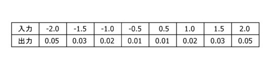
- FIG. 11 is a diagram for explaining the calculation of the air-fuel ratio correction start criteria in FIG. It shows the relationship between the input and the output when calculating the feedback correction amount in step ST24.
- Input air-fuel ratio deviation value
- Input is "-2.0", “-1.5”, “-1.0”, “-0.5”, “0.5”, “1.0”, “1 5” and “2.0”
- the outputs are respectively “0.05”, “0.03”, “0.02”, “0.01”, “0.01”, “0. 02", “0.03", and "0.05”.
- the deviation of the rich side peak value of the air-fuel ratio is large, it is preferable to reduce the feedback gain change amount.
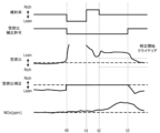
- FIG. 12 is a timing chart for explaining calculation of the A/F deviation.
- the fuel cut of the internal combustion engine 11 is performed, the correction of the air-fuel ratio is prohibited, and the air-fuel ratio correction is stopped.
- the accelerator opening signal ACC detects that the accelerator is turned on at the next time t1
- fuel cut recovery is performed and combustion of the internal combustion engine 11 is started again.
- fuel is increased (rich spike) and supplied while the air-fuel ratio feedback is stopped.
- the measured air-fuel ratio deviates from the target air-fuel ratio indicated by the dashed line from the rich spike to the resumption of the air-fuel ratio feedback control, as indicated by the solid line.
- the difference between the air-fuel ratio peak reference value and the measured value is the air-fuel ratio peak deviation value.
- FIG. 13 and 14 respectively show the air-fuel ratio, air-fuel ratio correction, and NOx generation status in the conventional control method and the internal combustion engine control method according to the embodiment of the present invention in comparison.
- FIG. 13 conventionally, between times t2 and t3, since the air-fuel ratio deviates from the target air-fuel ratio from the rich spike until the air-fuel ratio feedback control is restarted, NOx deteriorates. have a bad influence.
- the air-fuel ratio feedback control after fuel cut recovery is performed in a predetermined manner. can be resumed at an appropriate early timing without waiting for the timeout period to elapse.
- an internal combustion engine control apparatus and control method capable of suppressing deterioration of emissions during fuel cut recovery.
Landscapes
- Engineering & Computer Science (AREA)
- Chemical & Material Sciences (AREA)
- Combustion & Propulsion (AREA)
- Mechanical Engineering (AREA)
- General Engineering & Computer Science (AREA)
- Electrical Control Of Air Or Fuel Supplied To Internal-Combustion Engine (AREA)
Abstract
Description
従って、本発明によれば、燃料カットリカバー時におけるエミッションの悪化を抑制できる内燃機関の制御装置及びその制御方法を提供できる。
図1は、本発明の実施形態に係る内燃機関の制御装置について説明するためのもので、内燃機関11とその制御装置51の概略構成を示している。
内燃機関11において、吸気は、空気流量計12、電制スロットル弁13、コレクタ14の順に通過し、その後、各気筒に備わる吸気管15、吸気弁16を介して燃焼室17に吸引される。
なお、内燃機関11は、燃料噴射弁21が燃焼室17内に燃料を直接噴射する筒内直接噴射式内燃機関であってもよい。
そして、燃焼室17内の混合気は、点火プラグ23が発生する火花により着火燃焼し、燃焼により燃焼室17内で生じた排気ガスは、排気弁25を介して各気筒に備わる排気管26に排出される。
第1排気浄化触媒31及び第2排気浄化触媒33は、内燃機関11の排気を、酸素ストレージ能力を有する触媒(例えば、3元触媒)の作用で浄化する排気浄化装置である。
そして、第1排気浄化触媒31は、排気管26の集合部の直下に配置され、第2排気浄化触媒33は、第1排気浄化触媒31の下流の排気ダクト32に配置される。
空燃比センサ34は、排気の空燃比に応じたリニアな出力信号RABFを得る全域空燃比センサであり、第1排気浄化触媒31の上流に設けられる。
酸素センサ35は、排気中の酸素濃度に応じた起電力を発生し、理論空燃比を境に出力信号VO2R(出力電圧)が急変する。
例えば、酸素センサ35は、排気の空燃比が理論空燃比よりもリッチであるときに1V程度の電圧を出力し、排気の空燃比が理論空燃比よりもリーンであるときに0Vに近い電圧を出力する。
排気還流装置43は、排気管26とコレクタ14とを連通させる排気還流管41と、排気還流管41の開口面積の調整を通じて排気還流量を制御する排気還流制御弁42とを有する。
マイクロコンピュータ51Aは、マイクロプロセッサ51A1、不揮発性メモリ51A2、図示を省略した揮発性メモリなどを有する。
また、制御装置51は、アクセル開度信号ACCなどから電制スロットル弁13の目標開度TAを算出し、目標開度TAに応じて電制スロットル弁13のスロットルモータを制御する。
そして、制御装置51は、気筒別に、所定の噴射タイミングにおいて燃料噴射パルス幅TIの噴射パルス信号を燃料噴射弁21に出力し、内燃機関11に供給する燃料量を制御することで内燃機関11の空燃比を制御する。
また、制御装置51は、燃料の増量開始後における空燃比のリッチ側ピーク値に応じて、空燃比クライテリアを設定し、空燃比フィードバックの再開時に、予め設定された空燃比クライテリアの基準値を、空燃比のリッチ側ピーク値に応じて変更する機能を備える。
制御装置51は、空燃比制御部511、計測部512、制御判定部513、クライテリア算出部514及びフィードバック補正量算出部515の各機能をソフトウェアとして備える。
空燃比制御部511は、例えば、燃料噴射弁21を制御して第1排気浄化触媒31の下流の排気の空燃比をリッチからリーンに反転させる場合、燃料噴射量をPI制御によって漸減させて空燃比をリーン化させる。そして、第1排気浄化触媒31の下流の排気の空燃比がリーンに反転すると、燃料噴射量をPI制御によって漸増させて空燃比をリッチ化させる。
制御判定部513では、これらの検出信号に基づく演算処理を行って、制御判定動作を実行する。具体的には、燃料カットリカバー開始後の空燃比ピーク値を検知し、この空燃比のリッチ側ピーク値から空燃比のずれ量を検知する。ここで、ピーク値とは、空燃比の変化量(リッチからリーンへの変化点)が最大となる値である。ピーク値の検知判定は、燃料カット後の燃料増量開始後、実空燃比のパラメータ変化量の符号が反転(例えばプラスからマイナス)するところを検知することで実行する。この空燃比のピーク値の算出は、燃料カット後の燃料増量開始後、最初にリッチ側のピークを検知した値を算出することで行う。
ステップST1で車両が走行中でないと判定された場合、ステップST2でアクセルオフでないと判定された場合には、制御判定を終了して他の制御動作に戻る。
次のステップST20では、タイマのカウント値とクライテリアの比較を行う。「タイマのカウント値<クライテリア」のときには、「空燃比≧第1クライテリア」か否か判定する(ステップST21)。空燃比が第1クライテリアより大きいか等しいときには、「空燃比≦第2クライテリア」か否か判定する(ステップST22)。
また、ステップST18で燃料増量が終了していない場合、ステップST21で空燃比が第1クライテリアより小さい場合、及びステップST22で空燃比が第2クライテリアより大きい場合には、ステップST14に戻ってステップST22までの動作を繰り返す。
図7は、図6に対して時刻T1,T2間のATF応答遅れ期間があるが、時刻T2以降は図6と同様であり、空燃比の応答遅れがあってもエミッションの悪化は実質的に時刻T1,T2間であり排気への影響は少ない。
なお、図9は、図8に対して時刻T1,T2間のATF応答遅れ期間があるが、時刻T2以降は図8と同様であり、空燃比の応答遅れがあってもエミッションの悪化は実質的に時刻T1,T2間であり排気への影響は少ない。
その後、所定時間経過した時刻t3に空燃比の補正が許可されると、空燃比フィードバック制御が再開され、空燃比のずれ量は徐々に小さくなって目標空燃比に近付いていく。
これによって、燃料カットリカバー時におけるエミッションの悪化を抑制できる内燃機関の制御装置及びその制御方法を提供できる。
従って、燃料カットリカバー時におけるエミッションの悪化を抑制できる内燃機関の制御装置及びその制御方法が得られる。
Claims (11)
- 内燃機関の空燃比をフィードバック制御する内燃機関の制御装置であって、前記制御装置は、
前記内燃機関の燃料カット後に再度燃焼を開始するときに、空燃比フィードバックを停止した状態で燃料を増量して供給し、
前記燃料の増量開始後における空燃比のリッチ側ピーク値に応じて、空燃比クライテリアを設定し、
前記燃料の増量後に、前記設定された空燃比クライテリアとなったときに、前記空燃比フィードバックを開始する、
ように構成されている、ことを特徴とする内燃機関の制御装置。 - 前記制御装置による前記空燃比クライテリアの設定は、前記空燃比フィードバックの再開時に、予め設定された空燃比クライテリアの基準値を、前記空燃比のリッチ側ピーク値に応じて変更するものである、請求項1に記載の内燃機関の制御装置。
- 前記制御装置は、前記空燃比が前記設定された空燃比クライテリアに達しない場合、所定のタイムアウト時間により空燃比フィードバック制御を開始するように構成されている、請求項1に記載の内燃機関の制御装置。
- 前記空燃比のリッチ側ピーク値は、空燃比がリッチ側からリーン側へ反転したときの値である、請求項1に記載の内燃機関の制御装置。
- 前記制御装置は、前記空燃比のリッチ側ピークが燃料の増量期間中に生じた場合、増量が終了したときに前記リッチ側ピーク値に応じて空燃比フィードバック制御を開始するように構成されている、請求項1に記載の内燃機関の制御装置。
- 前記制御装置は、前記空燃比のリッチ側ピーク値の基準値を設定し、前記空燃比クライテリアは当該基準値と実際の空燃比のリッチ側ピーク値との偏差に応じて算出されるように構成されている、請求項1に記載の内燃機関の制御装置。
- 前記制御装置は、前記偏差がリッチ側のときは、前記空燃比クライテリアをリッチ側に設定し、前記偏差がリーン側のときは前記空燃比クライテリアをリーン側に設定するように構成されている、請求項6に記載の内燃機関の制御装置。
- 前記設定された空燃比クライテリアは、前記空燃比のリッチ側ピーク値よりもリーン側である、請求項1に記載の内燃機関の制御装置。
- 前記制御装置は、前記設定された空燃比クライテリアに応じて、空燃比制御のフィードバックゲイン変化量を変更するように構成されている、請求項1に記載の内燃機関の制御装置。
- 前記制御装置は、前記空燃比のリッチ側ピーク値の偏差が大きい場合は、前記フィードバックゲイン変化量を小さくするように構成されている、請求項9に記載の内燃機関の制御装置。
- 内燃機関の空燃比をフィードバック制御する内燃機関の制御方法であって、前記制御方法は、
前記内燃機関への燃料の供給をカットすることと、
前記燃料の供給のカット後に、再度前記内燃機関の燃焼を開始するとき、空燃比フィードバックを停止した状態で燃料の増量を行って内燃機関に供給することと、
前記燃料の増量開始後の空燃比のリッチ側ピーク値に応じて空燃比クライテリアを設定することと、
前記燃料の増量後に、前記設定された空燃比クライテリアとなったときに、前記空燃比フィードバックによる前記内燃機関の制御を開始することと、
を備えることを特徴とする内燃機関の制御方法。
Priority Applications (4)
| Application Number | Priority Date | Filing Date | Title |
|---|---|---|---|
| EP23752829.4A EP4481183A4 (en) | 2022-02-14 | 2023-02-06 | CONTROL DEVICE FOR INTERNAL COMBUSTION ENGINE AND ITS CONTROL METHOD |
| JP2023580240A JP7850185B2 (ja) | 2022-02-14 | 2023-02-06 | 内燃機関の制御装置及びその制御方法 |
| US18/838,017 US12378925B2 (en) | 2022-02-14 | 2023-02-06 | Apparatus and method for controlling internal combustion engine |
| CN202380016495.4A CN118525140A (zh) | 2022-02-14 | 2023-02-06 | 内燃机的控制装置及其控制方法 |
Applications Claiming Priority (2)
| Application Number | Priority Date | Filing Date | Title |
|---|---|---|---|
| JP2022020538 | 2022-02-14 | ||
| JP2022-020538 | 2022-02-14 |
Publications (1)
| Publication Number | Publication Date |
|---|---|
| WO2023153365A1 true WO2023153365A1 (ja) | 2023-08-17 |
Family
ID=87564327
Family Applications (1)
| Application Number | Title | Priority Date | Filing Date |
|---|---|---|---|
| PCT/JP2023/003800 Ceased WO2023153365A1 (ja) | 2022-02-14 | 2023-02-06 | 内燃機関の制御装置及びその制御方法 |
Country Status (5)
| Country | Link |
|---|---|
| US (1) | US12378925B2 (ja) |
| EP (1) | EP4481183A4 (ja) |
| JP (1) | JP7850185B2 (ja) |
| CN (1) | CN118525140A (ja) |
| WO (1) | WO2023153365A1 (ja) |
Citations (12)
| Publication number | Priority date | Publication date | Assignee | Title |
|---|---|---|---|---|
| JPH08303279A (ja) * | 1995-05-10 | 1996-11-19 | Daihatsu Motor Co Ltd | 減速時燃料カット制御方法 |
| JP2003013777A (ja) * | 2001-06-28 | 2003-01-15 | Mitsubishi Electric Corp | 内燃機関の空燃比制御装置 |
| JP2003172176A (ja) * | 2001-12-06 | 2003-06-20 | Toyota Motor Corp | 内燃機関の燃料供給制御方法及び装置 |
| JP2004346778A (ja) * | 2003-05-20 | 2004-12-09 | Fuji Heavy Ind Ltd | エンジンの燃料噴射制御装置 |
| JP2005337059A (ja) * | 2004-05-25 | 2005-12-08 | Mitsubishi Electric Corp | 内燃機関の制御装置 |
| JP2008121530A (ja) * | 2006-11-10 | 2008-05-29 | Nissan Motor Co Ltd | エンジンの空燃比制御装置 |
| JP2008138628A (ja) * | 2006-12-04 | 2008-06-19 | Toyota Motor Corp | 内燃機関の制御装置および内燃機関の制御方法 |
| JP2009133204A (ja) * | 2007-11-28 | 2009-06-18 | Toyota Motor Corp | 内燃機関の制御装置 |
| JP2009250163A (ja) * | 2008-04-09 | 2009-10-29 | Toyota Motor Corp | 可変圧縮比内燃機関の制御装置 |
| JP2013036439A (ja) * | 2011-08-10 | 2013-02-21 | Toyota Motor Corp | 内燃機関の空燃比制御装置 |
| JP2019074028A (ja) * | 2017-10-17 | 2019-05-16 | 三菱自動車工業株式会社 | 空燃比制御装置 |
| WO2019135276A1 (ja) | 2018-01-05 | 2019-07-11 | 日産自動車株式会社 | 内燃機関の空燃比制御方法および空燃比制御装置 |
Family Cites Families (6)
| Publication number | Priority date | Publication date | Assignee | Title |
|---|---|---|---|---|
| JP3824983B2 (ja) * | 2002-09-04 | 2006-09-20 | 本田技研工業株式会社 | リーン運転の際に同定器の演算を停止する内燃機関の空燃比制御装置 |
| JP4726541B2 (ja) * | 2004-12-06 | 2011-07-20 | 日立オートモティブシステムズ株式会社 | 内燃機関の空燃比制御装置 |
| JP4244237B2 (ja) * | 2007-06-04 | 2009-03-25 | 三菱電機株式会社 | 内燃機関の空燃比制御装置 |
| JP6256240B2 (ja) * | 2014-07-28 | 2018-01-10 | トヨタ自動車株式会社 | 内燃機関の制御装置 |
| JP2019002388A (ja) * | 2017-06-20 | 2019-01-10 | 株式会社デンソー | 空燃比制御装置 |
| US10975753B2 (en) * | 2019-07-30 | 2021-04-13 | GM Global Technology Operations LLC | Exhaust gas recirculation wide range air fuel sensor for rich equivalence ratio target rationality diagnostic |
-
2023
- 2023-02-06 WO PCT/JP2023/003800 patent/WO2023153365A1/ja not_active Ceased
- 2023-02-06 JP JP2023580240A patent/JP7850185B2/ja active Active
- 2023-02-06 US US18/838,017 patent/US12378925B2/en active Active
- 2023-02-06 CN CN202380016495.4A patent/CN118525140A/zh active Pending
- 2023-02-06 EP EP23752829.4A patent/EP4481183A4/en active Pending
Patent Citations (12)
| Publication number | Priority date | Publication date | Assignee | Title |
|---|---|---|---|---|
| JPH08303279A (ja) * | 1995-05-10 | 1996-11-19 | Daihatsu Motor Co Ltd | 減速時燃料カット制御方法 |
| JP2003013777A (ja) * | 2001-06-28 | 2003-01-15 | Mitsubishi Electric Corp | 内燃機関の空燃比制御装置 |
| JP2003172176A (ja) * | 2001-12-06 | 2003-06-20 | Toyota Motor Corp | 内燃機関の燃料供給制御方法及び装置 |
| JP2004346778A (ja) * | 2003-05-20 | 2004-12-09 | Fuji Heavy Ind Ltd | エンジンの燃料噴射制御装置 |
| JP2005337059A (ja) * | 2004-05-25 | 2005-12-08 | Mitsubishi Electric Corp | 内燃機関の制御装置 |
| JP2008121530A (ja) * | 2006-11-10 | 2008-05-29 | Nissan Motor Co Ltd | エンジンの空燃比制御装置 |
| JP2008138628A (ja) * | 2006-12-04 | 2008-06-19 | Toyota Motor Corp | 内燃機関の制御装置および内燃機関の制御方法 |
| JP2009133204A (ja) * | 2007-11-28 | 2009-06-18 | Toyota Motor Corp | 内燃機関の制御装置 |
| JP2009250163A (ja) * | 2008-04-09 | 2009-10-29 | Toyota Motor Corp | 可変圧縮比内燃機関の制御装置 |
| JP2013036439A (ja) * | 2011-08-10 | 2013-02-21 | Toyota Motor Corp | 内燃機関の空燃比制御装置 |
| JP2019074028A (ja) * | 2017-10-17 | 2019-05-16 | 三菱自動車工業株式会社 | 空燃比制御装置 |
| WO2019135276A1 (ja) | 2018-01-05 | 2019-07-11 | 日産自動車株式会社 | 内燃機関の空燃比制御方法および空燃比制御装置 |
Non-Patent Citations (1)
| Title |
|---|
| See also references of EP4481183A4 |
Also Published As
| Publication number | Publication date |
|---|---|
| EP4481183A4 (en) | 2026-02-25 |
| CN118525140A (zh) | 2024-08-20 |
| US20250154916A1 (en) | 2025-05-15 |
| US12378925B2 (en) | 2025-08-05 |
| JP7850185B2 (ja) | 2026-04-22 |
| JPWO2023153365A1 (ja) | 2023-08-17 |
| EP4481183A1 (en) | 2024-12-25 |
Similar Documents
| Publication | Publication Date | Title |
|---|---|---|
| JP5001183B2 (ja) | 内燃機関の空燃比制御装置 | |
| JP3314294B2 (ja) | 内燃機関の制御装置 | |
| US6035839A (en) | Method and apparatus for controlling the air-fuel ratio of an internal combustion engine | |
| JP2011226490A (ja) | 内燃機関の空燃比制御装置 | |
| JP7850185B2 (ja) | 内燃機関の制御装置及びその制御方法 | |
| JP3622273B2 (ja) | 内燃機関の制御装置 | |
| JP2001342885A (ja) | 内燃機関の燃料噴射制御装置 | |
| JP2000130221A (ja) | 内燃機関の燃料噴射制御装置 | |
| JPH07151000A (ja) | 内燃機関の空燃比制御装置 | |
| JP3812301B2 (ja) | 直噴火花点火式内燃機関の制御装置 | |
| JP2002309995A (ja) | 内燃機関の燃料性状判定装置 | |
| JP2004197693A (ja) | 内燃機関の空燃比制御装置 | |
| JP3601101B2 (ja) | 内燃機関の空燃比制御装置 | |
| JP3123357B2 (ja) | 内燃機関の空燃比制御装置 | |
| JP3603490B2 (ja) | 内燃機関の空燃比制御装置 | |
| JP3489204B2 (ja) | 内燃機関の制御装置 | |
| JP4258733B2 (ja) | 内燃機関の空燃比制御装置 | |
| JP7204426B2 (ja) | 内燃機関の燃料噴射制御装置 | |
| JP2019074028A (ja) | 空燃比制御装置 | |
| JP3678578B2 (ja) | 内燃機関のアイドル制御装置 | |
| JP4254520B2 (ja) | エンジンの空燃比制御装置 | |
| JP3591046B2 (ja) | 内燃機関の燃料噴射量制御装置 | |
| JP6056452B2 (ja) | 内燃機関の制御装置 | |
| JP3667520B2 (ja) | 内燃エンジンの空燃比制御装置 | |
| JPH08105342A (ja) | 内燃機関の空燃比制御装置 |
Legal Events
| Date | Code | Title | Description |
|---|---|---|---|
| 121 | Ep: the epo has been informed by wipo that ep was designated in this application |
Ref document number: 23752829 Country of ref document: EP Kind code of ref document: A1 |
|
| WWE | Wipo information: entry into national phase |
Ref document number: 202380016495.4 Country of ref document: CN |
|
| ENP | Entry into the national phase |
Ref document number: 2023580240 Country of ref document: JP Kind code of ref document: A |
|
| WWE | Wipo information: entry into national phase |
Ref document number: 18838017 Country of ref document: US |
|
| WWE | Wipo information: entry into national phase |
Ref document number: 2023752829 Country of ref document: EP |
|
| NENP | Non-entry into the national phase |
Ref country code: DE |
|
| ENP | Entry into the national phase |
Ref document number: 2023752829 Country of ref document: EP Effective date: 20240916 |
|
| WWP | Wipo information: published in national office |
Ref document number: 18838017 Country of ref document: US |
|
| WWG | Wipo information: grant in national office |
Ref document number: 18838017 Country of ref document: US |