WO2023157162A1 - 自立系統向け電源システム - Google Patents
自立系統向け電源システム Download PDFInfo
- Publication number
- WO2023157162A1 WO2023157162A1 PCT/JP2022/006335 JP2022006335W WO2023157162A1 WO 2023157162 A1 WO2023157162 A1 WO 2023157162A1 JP 2022006335 W JP2022006335 W JP 2022006335W WO 2023157162 A1 WO2023157162 A1 WO 2023157162A1
- Authority
- WO
- WIPO (PCT)
- Prior art keywords
- power
- output
- power supply
- voltage
- active
- Prior art date
- Legal status (The legal status is an assumption and is not a legal conclusion. Google has not performed a legal analysis and makes no representation as to the accuracy of the status listed.)
- Ceased
Links
Images


Classifications
-
- H—ELECTRICITY
- H02—GENERATION; CONVERSION OR DISTRIBUTION OF ELECTRIC POWER
- H02J—ELECTRIC POWER NETWORKS; CIRCUIT ARRANGEMENTS OR SYSTEMS FOR SUPPLYING OR DISTRIBUTING ELECTRIC POWER; SYSTEMS FOR STORING ELECTRIC ENERGY
- H02J3/00—Circuit arrangements for AC mains or AC distribution networks
- H02J3/38—Arrangements for feeding a single network from two or more generators or sources in parallel; Arrangements for feeding already energised networks from additional generators or sources in parallel
- H02J3/46—Controlling the sharing of generated power between the generators, sources or networks
-
- H—ELECTRICITY
- H02—GENERATION; CONVERSION OR DISTRIBUTION OF ELECTRIC POWER
- H02J—ELECTRIC POWER NETWORKS; CIRCUIT ARRANGEMENTS OR SYSTEMS FOR SUPPLYING OR DISTRIBUTING ELECTRIC POWER; SYSTEMS FOR STORING ELECTRIC ENERGY
- H02J3/00—Circuit arrangements for AC mains or AC distribution networks
- H02J3/38—Arrangements for feeding a single network from two or more generators or sources in parallel; Arrangements for feeding already energised networks from additional generators or sources in parallel
- H02J3/46—Controlling the sharing of generated power between the generators, sources or networks
- H02J3/48—Controlling the sharing of active power
-
- H—ELECTRICITY
- H02—GENERATION; CONVERSION OR DISTRIBUTION OF ELECTRIC POWER
- H02J—ELECTRIC POWER NETWORKS; CIRCUIT ARRANGEMENTS OR SYSTEMS FOR SUPPLYING OR DISTRIBUTING ELECTRIC POWER; SYSTEMS FOR STORING ELECTRIC ENERGY
- H02J3/00—Circuit arrangements for AC mains or AC distribution networks
- H02J3/38—Arrangements for feeding a single network from two or more generators or sources in parallel; Arrangements for feeding already energised networks from additional generators or sources in parallel
- H02J3/46—Controlling the sharing of generated power between the generators, sources or networks
- H02J3/50—Controlling the sharing of reactive power
-
- H—ELECTRICITY
- H02—GENERATION; CONVERSION OR DISTRIBUTION OF ELECTRIC POWER
- H02M—APPARATUS FOR CONVERSION BETWEEN AC AND AC, BETWEEN AC AND DC, OR BETWEEN DC AND DC, AND FOR USE WITH MAINS OR SIMILAR POWER SUPPLY SYSTEMS; CONVERSION OF DC OR AC INPUT POWER INTO SURGE OUTPUT POWER; CONTROL OR REGULATION THEREOF
- H02M1/00—Details of apparatus for conversion
- H02M1/0003—Details of control, feedback or regulation circuits
- H02M1/0038—Circuits or arrangements for suppressing, e.g. by masking incorrect turn-on or turn-off signals, e.g. due to current spikes in current mode control
-
- H—ELECTRICITY
- H02—GENERATION; CONVERSION OR DISTRIBUTION OF ELECTRIC POWER
- H02M—APPARATUS FOR CONVERSION BETWEEN AC AND AC, BETWEEN AC AND DC, OR BETWEEN DC AND DC, AND FOR USE WITH MAINS OR SIMILAR POWER SUPPLY SYSTEMS; CONVERSION OF DC OR AC INPUT POWER INTO SURGE OUTPUT POWER; CONTROL OR REGULATION THEREOF
- H02M7/00—Conversion of AC power input into DC power output; Conversion of DC power input into AC power output
- H02M7/42—Conversion of DC power input into AC power output without possibility of reversal
- H02M7/44—Conversion of DC power input into AC power output without possibility of reversal by static converters
- H02M7/48—Conversion of DC power input into AC power output without possibility of reversal by static converters using discharge tubes with control electrode or semiconductor devices with control electrode
- H02M7/493—Conversion of DC power input into AC power output without possibility of reversal by static converters using discharge tubes with control electrode or semiconductor devices with control electrode the static converters being arranged for operation in parallel
-
- H—ELECTRICITY
- H02—GENERATION; CONVERSION OR DISTRIBUTION OF ELECTRIC POWER
- H02J—ELECTRIC POWER NETWORKS; CIRCUIT ARRANGEMENTS OR SYSTEMS FOR SUPPLYING OR DISTRIBUTING ELECTRIC POWER; SYSTEMS FOR STORING ELECTRIC ENERGY
- H02J2105/00—Networks for supplying or distributing electric power characterised by their spatial reach or by the load
- H02J2105/10—Local stationary networks having a local or delimited stationary reach
-
- H—ELECTRICITY
- H02—GENERATION; CONVERSION OR DISTRIBUTION OF ELECTRIC POWER
- H02J—ELECTRIC POWER NETWORKS; CIRCUIT ARRANGEMENTS OR SYSTEMS FOR SUPPLYING OR DISTRIBUTING ELECTRIC POWER; SYSTEMS FOR STORING ELECTRIC ENERGY
- H02J3/00—Circuit arrangements for AC mains or AC distribution networks
- H02J3/28—Arrangements for balancing of the load in networks by storage of energy
- H02J3/32—Arrangements for balancing of the load in networks by storage of energy using batteries or super capacitors with converting means
-
- H—ELECTRICITY
- H02—GENERATION; CONVERSION OR DISTRIBUTION OF ELECTRIC POWER
- H02J—ELECTRIC POWER NETWORKS; CIRCUIT ARRANGEMENTS OR SYSTEMS FOR SUPPLYING OR DISTRIBUTING ELECTRIC POWER; SYSTEMS FOR STORING ELECTRIC ENERGY
- H02J3/00—Circuit arrangements for AC mains or AC distribution networks
- H02J3/38—Arrangements for feeding a single network from two or more generators or sources in parallel; Arrangements for feeding already energised networks from additional generators or sources in parallel
- H02J3/381—Dispersed generators
Definitions
- the embodiment of the present invention relates to a power supply system for an isolated system.
- Power supply systems for isolated grids that supply power to isolated grids that are not interconnected with large-scale power grids provided by electric power companies.
- Power supply systems for isolated grids are used, for example, in factories and predetermined areas, and are sometimes called microgrids.
- the power supply system includes a power supply device and a power conversion device that converts the power supplied from the power supply device into AC power suitable for the isolated grid and supplies the converted AC power to the isolated grid.
- Distributed power sources such as power storage devices, solar power generation devices, and wind power generation devices, are used as the power supply device.
- the embodiment of the present invention provides a power supply system for an isolated system that can stably supply power to an isolated system even when a plurality of voltage source voltage control type power converters are operated in parallel.
- a power supply system for an isolated system that supplies AC power to an isolated system, wherein a plurality of power supply devices are connected in parallel to the isolated system, and the plurality of power supply devices are connected in parallel to the isolated system.
- a plurality of voltage source voltage control type power conversion devices that convert the power supplied from the power source into AC power corresponding to the isolated system and supply the converted AC power to the isolated system; and the plurality of power conversion devices and a control device for controlling the power conversion operation of the power conversion device, wherein the control device calculates a plurality of active power command values of the plurality of power converters according to the active power required in the isolated system, and , calculating a plurality of reactive power command values of the plurality of power converters according to the reactive power required in the isolated system, and calculating the active power according to the active power command values for the plurality of power converters.
- a power supply system for an isolated grid that performs voltage control operation so as to output reactive power in accordance with the reactive power command value.
- a power supply system for an isolated system that can stably supply power to an isolated system even when a plurality of voltage source voltage control type power converters are operated in parallel. be done.
- BRIEF DESCRIPTION OF THE DRAWINGS It is a block diagram which represents typically the power supply system for isolated systems which concerns on embodiment. It is a block diagram which represents typically an example of the control apparatus which concerns on embodiment. BRIEF DESCRIPTION OF THE DRAWINGS It is a block diagram which represents typically an example of the power converter device which concerns on embodiment.
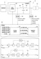
- FIG. 1 is a block diagram schematically showing a power supply system for an isolated grid according to an embodiment.
- a power supply system 2 for an isolated grid (hereinafter referred to as power supply system 2 ) includes a plurality of power supply devices 4 , a plurality of power conversion devices 6 , and a control device 10 .
- the power supply system 2 is connected to the isolated system IS.
- the isolated system IS is a system that is not interconnected with a large-scale power system provided by an electric power company or the like.
- the isolated system IS is an alternating current system.
- the AC power of the isolated system IS is, for example, three-phase AC power. However, the AC power of the isolated system IS may be single-phase AC power or the like.
- the power supply system 2 supplies AC power to the isolated grid IS.
- a plurality of power supply devices 4 are provided corresponding to a plurality of power conversion devices 6 .
- the number of power supply devices 4 is the same as the number of power conversion devices 6, for example.
- the plurality of power supply devices 4 are connected to each of the plurality of power electronics devices 6 .
- a plurality of power supply devices 4 may be connected to one power conversion device 6 .
- one power supply device 4 may be connected to a plurality of power electronics devices 6 .
- the number of power supply devices 4 does not necessarily have to be the same as the number of power electronics devices 6 .
- the plurality of power supply devices 4 supply power to each of the plurality of power conversion devices 6 .
- the plurality of power supply devices 4 are, for example, power storage devices using storage batteries.
- the plurality of power supply devices 4 supply DC power to each of the plurality of power conversion devices 6 .
- a plurality of power electronics devices 6 are provided corresponding to a plurality of power supply devices 4 .
- the plurality of power conversion devices 6 are connected to the plurality of power supply devices 4 and connected to the isolated grid IS.
- a plurality of power electronics devices 6 are connected in parallel to the isolated system IS.
- the plurality of power conversion devices 6 convert the power supplied from the plurality of power supply devices 4 into AC power corresponding to the isolated system IS, and supply the converted AC power to the isolated system IS.
- the plurality of power converters 6 are voltage source voltage control type power converters whose voltage is to be controlled. As a result, even when there is no other voltage source in the isolated system IS, power can be stably supplied to the isolated system IS. Also, the plurality of power converters 6 are operated in parallel. As a result, power can be stably supplied even to a relatively large isolated system IS.
- an AC load such as an induction motor is connected to the isolated system IS.
- the plurality of power electronics devices 6 power supply system 2 supply AC power to the AC load via the isolated grid IS.
- a synchronous generator may be connected to the isolated system IS.
- the isolated system IS may further be connected to, for example, a voltage source current control type power converter used in a storage battery system, a photovoltaic power generation system, or the like. In other words, the isolated system IS may be linked with another power source.
- the plurality of power conversion devices 6 When the plurality of power supply devices 4 are power storage devices, the plurality of power conversion devices 6 further have a function of charging the plurality of power supply devices 4 by converting the AC power of the isolated system IS into DC power.
- the plurality of power supply devices 4 are not limited to power storage devices, and may be, for example, solar battery panels.
- the plurality of power converters 6 may not have the function of converting AC power input from the isolated grid IS into DC power.
- the plurality of power supply devices 4 may be, for example, other power generators such as wind power generators and gas turbine power generators.
- the power input from the plurality of power supply devices 4 to the plurality of power conversion devices 6 is not limited to DC power, and may be AC power.
- the plurality of power conversion devices 6 may be configured to convert the AC power input from the plurality of power supply devices 4 into another AC power corresponding to the isolated grid IS.
- the conversion of electric power by the plurality of power converters 6 is not limited to conversion from DC to AC, but may be any conversion that converts the power of the plurality of power supply devices 4 into AC power corresponding to the isolated grid IS. good.
- the power supply system 2 further includes, for example, multiple transformers 12 and a measuring device 14 .
- a plurality of transformers 12 are provided corresponding to each of the plurality of power converters 6 .
- a plurality of power converters 6 are connected to the primary sides of a plurality of transformers 12 .
- the secondary sides of the plurality of transformers 12 are connected to the isolated system IS. In this way, the plurality of power converters 6 are connected to the isolated grid IS via the plurality of transformers 12 .
- a plurality of power converters 6 are connected in parallel via a plurality of transformers 12 to the isolated system IS.
- a circuit breaker or more transformers may be provided between the plurality of power converters 6 and the isolated system IS.
- the configuration between the plurality of power converters 6 and the isolated system IS may be any configuration that allows the plurality of power converters 6 to be connected to the isolated system IS.
- the measuring device 14 measures the active power and voltage at the control points of the plurality of power conversion devices 6 and inputs the active power measurement value and voltage measurement value to the control device 10 .
- the control points of the plurality of power converters 6 are, in other words, connection points (interconnection points) between the plurality of power converters 6 and the isolated grid IS.
- control points for active power control of the plurality of power converters 6 do not necessarily have to be the same as the control points for voltage control of the plurality of power converters 6 .
- the measuring device 14 may include, for example, a power measuring device that measures active power at the control point of active power control and a voltage measuring device that measures voltage at the control point of voltage control.
- the control device 10 controls power conversion operations of the plurality of power conversion devices 6 .
- the control device 10 communicates with the measurement device 14 and receives input from the measurement device 14 of control point active power measurement information and control point voltage measurement information.
- the control device 10 also communicates with, for example, each of the plurality of power supply devices 4 and receives input of information regarding the plurality of power supply devices 4 from each of the plurality of power supply devices 4 .
- the control device 10 controls the operations of the plurality of power converters 6 based on the input information.
- the information regarding the plurality of power source devices 4 is, for example, information regarding the chargeable/dischargeable amount of the plurality of power source devices 4 . More specifically, it is information on the remaining amount of charge (SOC: State Of Charge) of the power supply device 4 .
- the information on the remaining amount of stored electricity may be information representing the remaining amount of stored electricity itself, or the remaining amount of stored electricity (information on the chargeable/dischargeable amount) can be calculated in the control device 10, such as the voltage of the power supply device 4, for example.
- Information such as The information about the chargeable/dischargeable amount is not limited to the above, and may be any information that enables the control device 10 to grasp the chargeable/dischargeable amount of the power supply device 4 .
- the information regarding the plurality of power source devices 4 is, for example, information regarding the amount of power generated by the plurality of power source devices 4 .
- the information input to the control device 10 is not limited to the above.
- the control device 10 communicates with each of the plurality of power converters 6 to obtain information on the active power output value of each of the plurality of power converters 6 and the reactive power output of each of the plurality of power converters 6. Input such as value information may be received.
- the information input to the control device 10 may be arbitrary information required for controlling the plurality of power electronics devices 6 .
- each piece of information may be input to the control device 10 from, for example, a higher-level controller or the like.
- the control device 10 does not necessarily have to directly communicate with the measuring device 14, the plurality of power supply devices 4, and the like.
- a method of inputting each piece of information to the control device 10 may be any method that can appropriately input each piece of information to the control device 10 .
- FIG. 2 is a block diagram schematically showing an example of the control device according to the embodiment.
- the control device 10 has an active power command value calculator 20 , a reactive power total value calculator 22 , and a reactive power command value calculator 24 .
- the control device 10 calculates the active power command value and the reactive power command value of each of the plurality of power conversion devices 6 based on each input information, and divides the calculated active power command value and reactive power command value into a plurality of By inputting to each of the power converters 6, the power conversion operation of the plurality of power converters 6 is controlled.
- the active power command value calculation unit 20 receives an active power total value representing the magnitude of the active power to be output from the plurality of power converters 6 as a whole. In the case where the isolated system IS is not powered by any other source, the control point active power measurement can be taken as the amount of active power currently required in the isolated system IS. Therefore, the control device 10 inputs the active power measurement value input from the measuring device 14 to the active power command value calculation unit 20 as the active power total value.
- the active power measurement value at the control point is approximately the same as the sum of the active power output values of the plurality of power converters 6 . Therefore, the control device 10 acquires information on the active power output values of each of the plurality of power conversion devices 6, and inputs the total value of the active power output values to the active power command value calculation unit 20 as the total active power value. good too.
- the active power command value calculation unit 20 calculates a plurality of active power command values representing the magnitude of the active power to be individually output from each of the plurality of power converters 6 based on the input active power total value. .
- the active power command value calculation unit 20 performs proportional division processing of the multiple active power command values, for example, so that the magnitude of the active power is appropriate according to the respective states of the multiple power converters 6 .
- the active power command value calculation unit 20 determines that the power conversion device 6 corresponding to the power supply device 4 with a higher remaining power storage amount has a higher remaining power storage amount.
- the magnitude of the active power during discharge is greater than that of the power conversion device 6 corresponding to the power supply device 4 having a low amount of electricity, and the power conversion device 6 corresponding to the power supply device 4 having a large remaining amount of stored electricity has a larger amount of stored electricity.
- a plurality of active power command values are proportionally divided so that the magnitude of the active power during charging is smaller than that of the power conversion device 6 corresponding to the power supply device 4 with a low remaining amount.
- the active power command value calculation unit 20 performs proportional division processing based on information regarding the plurality of power supply devices 4, for example.
- the active power total value (unit: W) is P Total
- the active power command value (unit: W) of each of the plurality of power conversion devices 6 is P ref (i)
- each of the plurality of power supply devices 4 When the remaining amount of stored electricity (unit: %) is SOC(i) and the total value of the remaining amount of stored electricity (unit: %) of the plurality of power supply devices 4 is SOC Total , active power command value calculation unit 20 calculates the active power command value P ref (i) for each of the plurality of power converters 6 by the following equation (1) during discharging (P Total > 0).
- the ratio of the remaining amount of individual stored electricity to the total value of the remaining amount of stored electricity is calculated, and the ratio is multiplied by the total value of active power.
- the power conversion device 6 corresponding to the power supply device 4 with a high remaining amount of stored electricity is more likely to discharge than the power conversion device 6 corresponding to the power supply device 4 with a lower remaining amount of stored electricity.
- Proportional division processing can be performed so that the magnitude of the active power at is increased.
- the power command value calculation unit 20 calculates active power command values P ref (i) for each of the plurality of power converters 6 according to the following equation (2).
- Pref (i) PTotal *(BAU(i)/ BAUTotal ) (2)
- BAU Total is, in other words, the total value of a plurality of BAU(i).
- the power conversion device 6 corresponding to the power supply device 4 with a high remaining amount of stored electricity is faster than the power conversion device 6 corresponding to the power supply device 4 with a low remaining amount of stored electricity during charging.
- Proportional division processing can be performed so that the magnitude of the active power at is reduced.
- the active power command value calculation unit 20 determines that the power conversion device 6 corresponding to the power supply device 4 having a high power generation amount is the power supply device 4 having a low power generation amount.
- a plurality of active power command values are proportionally divided so that the magnitude of the active power is larger than that of the power conversion device 6 corresponding to .
- This proportional division process can be calculated by, for example, replacing the remaining amount SOC(i) of the amount of electricity stored in the above equation (1) with the amount of power generation.
- the active power command value calculation unit 20 does not necessarily have to perform the proportional division process as described above.
- the active power command value calculation unit 20 may calculate an average value obtained by dividing the active power total value by the number of the plurality of power converters 6 as the plurality of active power command values.
- the target voltage value of the control point and the measured voltage value of the control point input from the measuring device 14 are input to the reactive power total value calculation unit 22 .
- the voltage target value may be a preset constant value, or may be a variable input from a host controller or the like.
- the reactive power total value calculation unit 22 calculates a reactive power total value representing the magnitude of the reactive power to be output from the plurality of power converters 6 as a whole based on the input voltage target value and voltage measurement value. .
- the reactive power total value calculator 22 calculates the reactive power total value by, for example, calculating the difference between the voltage target value and the voltage measurement value and performing PI control on the calculated difference.
- the reactive power total value calculation unit 22 increases the reactive power total value when the voltage measurement value is lower than the voltage target value, and increases the reactive power total value when the voltage measurement value is higher than the voltage target value. Calculate the total reactive power value so as to make it smaller. As a result, the voltage measurement value can be brought closer to the voltage target value, and control can be performed to keep the voltage at the control point constant.
- the calculation of the reactive power total value by the reactive power total value calculation unit 22 is not limited to PI control, and may be proportional control, PID control, or the like.
- the calculation of the reactive power total value by the reactive power total value calculator 22 may be any calculation that can appropriately calculate the reactive power total value based on the voltage target value and the voltage measurement value.
- the reactive power total value calculation unit 22 inputs the calculated reactive power total value to the reactive power command value calculation unit 24 .
- the calculation of the reactive power total value may be performed by a host controller or the like and input to the control device 10 .
- the control device 10 does not necessarily have to have the reactive power total value calculator 22 .
- the reactive power command value calculation unit 24 calculates a plurality of reactive power command values representing the magnitude of reactive power to be individually output from each of the plurality of power converters 6 based on the input reactive power total value. .
- the reactive power command value calculation unit 24 performs proportional division processing of a plurality of reactive power command values so as to obtain an appropriate magnitude of reactive power in consideration of the respective reactive power output upper limits of the plurality of power converters 6.
- the reactive power command value calculation unit 24 calculates, for example, an average value obtained by dividing the total value of reactive power by the number of the plurality of power converters 6 . After that, the reactive power command value calculation unit 24 confirms whether or not the average value exceeds the reactive power output upper limit for each of the plurality of power converters 6 .
- the excess is allocated to the power conversion device 6 that has a surplus. That is, the excess is added to the reactive power command value of another power converter 6 that does not exceed the reactive power output upper limit, and the reactive power command value of the power converter 6 that exceeds the reactive power output upper limit is equal to the reactive power output upper limit. limit to
- the reactive power command value calculation unit 24 sets the total value of reactive power to the upper limit of the reactive power output. limited to the sum of
- the reactive power output upper limit of each of the plurality of power converters 6 may be a preset constant value, or may be a variable input from a higher-level controller or the like.
- the reactive power command value calculation unit 24 does not necessarily have to perform the proportional division process as described above.
- the reactive power command value calculation unit 24 may calculate an average value obtained by dividing the reactive power total value by the number of the plurality of power converters 6 as the plurality of reactive power command values.
- the control device 10 calculates the active power command values of the plurality of power conversion devices 6 calculated by the active power command value calculation unit 20 and the respective power conversion devices 6 calculated by the reactive power command value calculation unit 24. is input to each of the plurality of power converters 6. Thereby, the control device 10 controls the power conversion operation of the plurality of power conversion devices 6 .
- control device 10 is not limited to the above.
- the control device 10 may be configured to calculate the active power total value from the difference between the active power target value of the control point and the active power measurement value of the control point.
- the configuration of the control device 10 may be any configuration that can appropriately calculate a plurality of active power command values and a plurality of reactive power command values based on a plurality of input information.
- FIG. 3 is a block diagram schematically showing an example of the power converter according to the embodiment.
- the power conversion device 6 includes a main circuit section 30, a control section 32, and measuring instruments 34 and 36.
- the main circuit unit 30 converts electric power.
- the control unit 32 controls power conversion by the main circuit unit 30 . Since the configurations of the plurality of power electronics devices 6 are substantially the same, only the configuration of one power electronics device 6 will be described here.
- the main circuit section 30 is connected to the power supply device 4 and the isolated system IS.
- the main circuit unit 30 converts, for example, DC power input from the power supply device 4 into AC power corresponding to the isolated system IS, outputs the converted AC power to the isolated system IS, and receives input from the isolated system IS.
- the power supply device 4 is charged by converting the AC power into DC power.
- the main circuit section 30 connects the power supply device 4 with the isolated system IS.
- the conversion of power by the main circuit unit 30 is not limited to the conversion from DC to AC, and may be any conversion that converts the power of the power supply device 4 into AC power corresponding to the isolated grid IS.
- the main circuit section 30 has a power conversion section 40 and a filter circuit 42 .
- the power converter 40 converts power.
- the power converter 40 has, for example, a plurality of switching elements, and performs power conversion by switching the plurality of switching elements.
- the power converter 40 has, for example, a plurality of switching elements connected in a three-phase bridge.
- the configuration of the power conversion unit 40 may be any configuration that can convert input power into AC power compatible with the isolated grid IS by switching a plurality of switching elements or the like.
- the filter circuit 42 is provided on the AC side of the power converter 40 .
- the filter circuit 42 is provided between the power converter 40 and the isolated grid IS.
- the filter circuit 42 is provided between the power converter 40 and the transformer 12 .
- the filter circuit 42 makes the AC power output from the power converter 40 approximate a sine wave.
- the filter circuit 42 brings the AC power output from the power conversion unit 40 closer to a sine wave by, for example, suppressing high-frequency components contained in the AC power output from the power conversion unit 40 .
- the filter circuit 42 includes, for example, reactors 44 and 45 connected in series to the AC output point of the power conversion section 40, and a capacitor 46 connected in parallel to the AC output point of the power conversion section 40. have. Note that the reactors 44 and 45 and the capacitor 46 are provided for each phase of the AC power output from the power converter 40 .
- the reactor 45 is connected in series with the reactor 44 .
- reactor 45 is provided between reactor 44 and transformer 12 .
- the capacitor 46 is connected in parallel to the AC output point of the power converter 40 by being connected to the connection point of the reactors 44 and 45 .
- a plurality of power converters 6 are connected in parallel to the isolated system IS via transformers 12 and reactors 45 . Accordingly, the reactance components of the transformer 12 and the reactor 45 can more appropriately suppress the occurrence of cross currents between the plurality of power converters 6 .
- the configuration of the filter circuit 42 is not limited to the above, and may be any configuration that can make the AC power output from the power converter 40 approximate a sine wave.
- the reactor 45 of the filter circuit 42 may be omitted if the transformer 12 alone can appropriately suppress the generation of the cross current.
- the transformer 12 may be omitted. That is, the plurality of power converters 6 are connected in parallel to the isolated system IS via at least one of the transformer 12 and the reactor 45 . Accordingly, the reactance component of at least one of the transformer 12 and the reactor 45 can suppress the occurrence of cross currents between the plurality of power converters 6 .
- the measuring device 34 measures the phase voltages Va (INV), Vb (INV), Vc (INV) of each phase of the AC power output from the power converter 40, and the line currents Ia (INV), Ib (INV ) and Ic(INV), and input the measurement results to the control unit 32 .
- the measuring device 36 measures the phase voltages Va (PCS), Vb (PCS), and Vc (PCS) of each phase of the AC power output from the main circuit section 30 (filter circuit 42), and the line current Ia (PCS) of each phase. , Ib(PCS), Ic(PCS), the active power P(PCS) at the output terminal of the main circuit section 30, and the reactive power Q(PCS) at the output terminal of the main circuit section 30 are measured, and the measurement results are sent to the control section. 32.
- the control unit 32 controls power conversion by the main circuit unit 30 by controlling the operation of the power conversion unit 40 .
- the controller 32 controls switching of the plurality of switching elements of the power converter 40 .
- the measurement results of the measuring instruments 34 and 36 are input to the control unit 32 , and the active power command value and reactive power command value of the AC power output from the main circuit unit 30 are input from the control device 10 .
- the control unit 32 controls the operation of the power conversion unit 40 based on the measurement results input from the measuring instruments 34 and 36 and the active power command value and reactive power command value input from the control device 10. .
- the control unit 32 outputs an instantaneous value voltage output command for each phase of the AC power output from the power conversion unit 40.
- Values Va(ref), Vb(ref), and Vc(ref) are calculated, and voltages corresponding to the calculated instantaneous voltage output command values Va(ref), Vb(ref), and Vc(ref) are supplied to the power converter 40 The operation of the power conversion unit 40 is controlled so that the output is from.
- control unit 32 controls the output voltage of the main circuit unit 30.
- the control unit 32 performs voltage control operation of the main circuit unit 30 .
- each measurement result is not limited to being input directly from the measuring instruments 34 and 36 to the control unit 32, and may be input to the control unit 32 via, for example, a higher-level controller.
- the measured value of active power P (PCS) at the output terminal of main circuit section 30 and the measured value of reactive power Q (PCS) at the output terminal of main circuit section 30 are input from measuring instrument 36 to control section 32.
- phase voltages Va (PCS), Vb (PCS), and Vc (PCS) of each phase and line currents Ia (PCS), Ib (PCS), and Ic (PCS) of each phase are not limited to the configuration. It may be obtained by calculation within the control unit 32 based on the measured value.
- the measuring device 36 does not necessarily have to measure the active power P(PCS) and the reactive power Q(PCS).
- the control unit 32 has a command value calculation unit 50 and a control signal generation unit 52 .
- the active power command value and the reactive power command value input from the control device 10 are input to the command value calculation unit 50, and the active power P (PCS) and the reactive power Q (PCS) measured by the measuring device 36 are input. are entered.
- the measured value of the active power P(PCS) is, in other words, the current active power output value Output of the main circuit section 30 .
- the measured value of the reactive power Q (PCS) is, in other words, the current reactive power output value Qoutput of the main circuit section 30 .
- the command value calculation unit 50 outputs active power corresponding to the active power command value Pref and reactive power corresponding to the reactive power command value Qref from the main circuit unit 30, the input active power command value Pref and reactive power Based on the command value Qref, the active power output value Poutput, and the reactive power output value Qoutput, the output voltage phase ⁇ ref, the output voltage frequency fref, and the output voltage amplitude Vref of the AC power output from the main circuit section 30 are calculated.
- the command value calculation unit 50 performs the above calculations, for example, using a voltage source voltage control type control logic such as a generator oscillation equation and droop control.
- the command value calculator 50 calculates the output voltage phase ⁇ ref and the output voltage frequency fref based on the active power command value Pref and the active power output value Output, for example. Then, the command value calculation unit 50 calculates the output voltage amplitude Vref based on, for example, the reactive power command value Qref and the reactive power output value Qoutput.
- the command value calculator 50 inputs the calculated output voltage phase ⁇ ref, output voltage frequency fref, and output voltage amplitude Vref to the control signal generator 52 .
- a well-known calculation method may be used to calculate the output voltage phase ⁇ ref, the output voltage frequency fref, and the output voltage amplitude Vref.
- the information used for calculation by the command value calculator 50 is not limited to only the active power command value Pref, the reactive power command value Qref, the active power output value Output, and the reactive power output value Qoutput, and may include other information.
- the configuration of the command value calculation unit 50 is such that based on at least the active power command value Pref, the reactive power command value Qref, the active power output value Output, and the reactive power output value Qoutput, the output voltage phase ⁇ ref, the output voltage frequency fref, and the output Any configuration that can calculate the voltage amplitude Vref may be used.
- the control signal generation unit 52 Based on the input output voltage phase ⁇ ref, output voltage frequency fref, and output voltage amplitude Vref, the control signal generation unit 52 generates an instantaneous voltage output command value Va(ref) for each phase of the AC power of the power conversion unit 40. , Vb(ref) and Vc(ref).
- the control signal generation unit 52 generates, for example, control signals for outputting voltages corresponding to the instantaneous voltage output command values Va(ref), Vb(ref), and Vc(ref) of each phase from the power conversion unit 40. and inputs the generated control signal to the power conversion unit 40 .
- the control signal generation unit 52 causes the power conversion unit 40 to output voltages corresponding to the instantaneous voltage output command values Va(ref), Vb(ref), and Vc(ref) of each phase.
- the control signal generation unit 52 causes the power conversion unit 40 to output voltages corresponding to the instantaneous voltage output command values Va(ref), Vb(ref), and Vc(ref).
- the control signal generation unit 52 causes the power conversion unit 40 to output a voltage corresponding to the instantaneous voltage output command values Va(ref), Vb(ref), and Vc(ref), thereby generating a voltage corresponding to the active power command value Pref.
- Active power and reactive power according to the reactive power command value Qref are output from the main circuit section 30 .
- the control signal generation unit 52 performs sine wave pulse width modulation control based on, for example, the instantaneous voltage output command values Va (ref), Vb (ref), and Vc (ref) of each phase, so that the power conversion unit A control signal is generated for controlling the switching of each switching element of 40 .
- the configuration of the control signal generation unit 52 is not limited to this, and the voltage corresponding to the instantaneous voltage output command values Va (ref), Vb (ref), and Vc (ref) of each phase is generated from the power conversion unit 40. Any configuration capable of generating a control signal for output may be used.
- the function of performing sinusoidal pulse width modulation control may be provided on the power converter 40 side.
- the control signal generation unit 52 may input, for example, the instantaneous voltage output command values Va(ref), Vb(ref), and Vc(ref) of each phase to the power conversion unit 40 as control signals.
- control signal generator 52 receives, for example, the output voltage phase ⁇ ref, the output voltage frequency fref, and the output voltage amplitude Vref, and the phase voltages Va (INV), Vb (INV ), Vc (INV), line currents Ia (INV), Ib (INV), Ic (INV), and phase voltages Va (PCS), Vb (PCS), Vc (PCS) measured by measuring instrument 36, line Measured values of currents Ia (PCS), Ib (PCS), and Ic (PCS) are input.
- the control signal generator 52 uses the output voltage phase ⁇ ref, the output voltage frequency fref, and the output voltage amplitude Vref, and also generates phase voltages Va (INV), Vb (INV), Vc (INV), line current Ia (INV), At least each input information of Ib (INV), Ic (INV), phase voltages Va (PCS), Vb (PCS), Vc (PCS), and line currents Ia (PCS), Ib (PCS), Ic (PCS) By using any one of them, the instantaneous voltage output command values Va(ref), Vb(ref), and Vc(ref) are calculated so as to suppress overcurrent at the output terminal of the main circuit section 30 .
- the voltage control operation can be performed.
- the occurrence of overcurrent can also be suppressed. For example, when an instantaneous potential difference occurs due to a sudden change in the system voltage, etc., an overcurrent occurs in the main circuit unit 30, and parts inside the main circuit unit 30 such as the switching elements of the power conversion unit 40 malfunction. You can prevent it from happening.
- the control unit 32 controls the control unit 30 when the magnitude of the active power of the AC power output from the main circuit unit 30 has changed from the active power command value due to overcurrent suppression, or when the main circuit unit 30 has changed due to overcurrent suppression.
- the change in active power or the change in reactive power is notified to the control device 10 .
- the control device 10 receives a notification of a change in active power or a change in reactive power from the control device 10 of a predetermined power conversion device 6, the control device 10 controls the operation of the other power conversion device 6 so as to adjust the amount of change. do.
- the method of calculating the instantaneous voltage output command values Va (ref), Vb (ref), and Vc (ref) so as to suppress overcurrent using at least one of the above input information is, for example, PCT /JP2021/012721 and PCT/JP2021/012723.
- control signal generator 52 may not necessarily be configured to calculate the instantaneous voltage output command value so as to suppress overcurrent.
- the control signal generator 52 may be configured to be capable of calculating the instantaneous voltage output command value based on at least the output voltage phase, the output voltage frequency, and the output voltage amplitude.
- the configuration of the control unit 32 can calculate the output voltage phase, the output voltage frequency, and the output voltage amplitude based on the active power command value, the reactive power command value, the active power output value, and the reactive power output value. Based on the output voltage phase, the output voltage frequency, and the output voltage amplitude, the instantaneous voltage output command value can be calculated, and a voltage corresponding to the instantaneous voltage output command value is output from the power conversion unit 40. Any configuration that can control the operation of the power conversion unit 40 may be used.
- the control device 10 calculates the active power command value of each power conversion device 6 according to the active power required by the isolated grid IS, and each power conversion device 6 Voltage control operation is performed so as to output active power according to the power command value. As a result, even when a plurality of voltage source voltage control type power converters 6 are operated in parallel, fluctuations in the frequency of the isolated system IS can be suppressed. Further, in the power supply system 2 according to the present embodiment, the control device 10 calculates the reactive power command value of each power conversion device 6 according to the reactive power required in the isolated grid IS, and each power conversion device 6 , voltage control operation is performed so as to output reactive power according to the reactive power command value.
- the inventors of the present application have considered the active power and reactive power that can be output by a plurality of power converters 6, and set appropriate active power command values and reactive power command values to a plurality of power converters 6. , it is possible to supply power more stably to the isolated system even when a plurality of voltage source voltage control type power converters are operated in parallel.
- the control device 10 performs proportional division processing of the plurality of active power command values so that the magnitude of the active power is appropriate according to the state of each of the plurality of power converters 6.
- proportional division processing is performed on a plurality of reactive power command values so as to obtain an appropriate magnitude of reactive power in consideration of the upper limit of reactive power output of each of the plurality of power converters 6 .
- the inventors of the present application have found that by suppressing the occurrence of cross currents between the plurality of power converters 6, when a plurality of voltage source voltage control type power converters are operated in parallel, It was also found that more stable power supply to the isolated system can be performed.
- a plurality of power converters 6 are connected in parallel to the isolated system IS via at least one of the transformer 12 and the reactor 45 .
Landscapes
- Engineering & Computer Science (AREA)
- Power Engineering (AREA)
- Supply And Distribution Of Alternating Current (AREA)
- Inverter Devices (AREA)
Abstract
Description
なお、図面は模式的または概念的なものであり、各部分の厚みと幅との関係、部分間の大きさの比率などは、必ずしも現実のものと同一とは限らない。また、同じ部分を表す場合であっても、図面により互いの寸法や比率が異なって表される場合もある。
なお、本願明細書と各図において、既出の図に関して前述したものと同様の要素には同一の符号を付して詳細な説明は適宜省略する。
図1に表したように、自立系統向け電源システム2(以下、電源システム2と称す)は、複数の電源装置4と、複数の電力変換装置6と、制御装置10と、を備える。
図2に表したように、制御装置10は、有効電力指令値演算部20と、無効電力合計値演算部22と、無効電力指令値演算部24と、を有する。制御装置10は、入力された各情報を基に、複数の電力変換装置6のそれぞれの有効電力指令値及び無効電力指令値を演算し、演算した有効電力指令値及び無効電力指令値を複数の電力変換装置6のそれぞれに入力することにより、複数の電力変換装置6の電力の変換動作を制御する。
Pref(i)=PTotal×(SOC(i)/SOCTotal)・・・(1)
なお、(i)は、複数の電力変換装置6及び対応する電源装置4を個別に表す変数である。SOCTotalは、換言すれば、複数のSOC(i)の合計値である。
Pref(i)=PTotal×(BAU(i)/BAUTotal)・・・(2)
なお、BAU(i)は、BAU(i)=100-SOC(i)である。BAUTotalは、換言すれば、複数のBAU(i)の合計値である。
図3に表したように、電力変換装置6は、主回路部30と、制御部32と、測定器34、36と、を備える。主回路部30は、電力の変換を行う。制御部32は、主回路部30による電力の変換を制御する。なお、複数の電力変換装置6の構成は、実質的に同じであるから、ここでは、1つの電力変換装置6の構成についてのみ説明を行う。
Claims (6)
- 自立系統への交流電力の供給を行う自立系統向け電源システムであって、
複数の電源装置と、
前記自立系統に対して並列に接続され、前記複数の電源装置から供給された電力を前記自立系統に対応した交流電力に変換し、変換後の前記交流電力を前記自立系統に供給する電圧源電圧制御型の複数の電力変換装置と、
前記複数の電力変換装置の電力の変換動作を制御する制御装置と、
を備え、
前記制御装置は、前記自立系統で必要とされる有効電力に応じた前記複数の電力変換装置の複数の有効電力指令値を演算するとともに、前記自立系統で必要とされる無効電力に応じた前記複数の電力変換装置の複数の無効電力指令値を演算し、
前記複数の電力変換装置は、前記有効電力指令値に応じた有効電力を出力するとともに、前記無効電力指令値に応じた無効電力を出力するように電圧制御運転を行う自立系統向け電源システム。 - 前記制御装置は、前記複数の電力変換装置のそれぞれの状態に応じた有効電力の大きさとなるように、前記複数の有効電力指令値の按分処理を行うとともに、前記複数の電力変換装置のそれぞれの無効電力出力上限を考慮した無効電力の大きさとなるように、前記複数の無効電力指令値の按分処理を行う請求項1記載の自立系統向け電源システム。
- 前記複数の電源装置は、前記複数の電力変換装置に直流電力を供給する蓄電装置であり、
前記複数の電力変換装置は、前記複数の電源装置から供給された直流電力を前記自立系統に対応した交流電力に変換し、変換後の前記交流電力を前記自立系統に供給するとともに、前記自立系統の前記交流電力を直流電力に変換することにより、前記複数の電源装置を充電し、
前記制御装置は、蓄電量の残量の高い前記電源装置に対応する前記電力変換装置の方が、蓄電量の残量の低い前記電源装置に対応する前記電力変換装置よりも放電時における有効電力の大きさが大きくなり、蓄電量の残量の高い前記電源装置に対応する前記電力変換装置の方が、蓄電量の残量の低い前記電源装置に対応する前記電力変換装置よりも充電時における有効電力の大きさが小さくなるように、前記複数の有効電力指令値の按分処理を行う請求項2記載の自立系統向け電源システム。 - 前記複数の電力変換装置は、前記自立系統に対し、変圧器及びリアクトルの少なくとも一方を介して並列に接続される請求項1記載の自立系統向け電源システム。
- 前記複数の電力変換装置は、電力の変換を行う主回路部と、前記主回路部による電力の変換を制御する制御部と、を有し、
前記主回路部は、電力の変換を行う電力変換部と、前記電力変換部と前記自立系統との間に設けられたフィルタ回路と、を有し、
前記制御部は、
前記有効電力指令値、前記無効電力指令値、前記主回路部の現在の有効電力出力値、及び前記主回路部の現在の無効電力出力値を基に、前記主回路部から出力する交流電力の出力電圧位相、出力電圧周波数、及び出力電圧振幅を演算し、
前記出力電圧位相、前記出力電圧周波数、及び前記出力電圧振幅を基に、前記電力変換部の交流電力の瞬時値電圧出力指令値を演算し、
前記瞬時値電圧出力指令値に応じた電圧を前記電力変換部から出力させるように、前記電力変換部の動作を制御する請求項1記載の自立系統向け電源システム。 - 前記制御部は、前記出力電圧位相、前記出力電圧周波数、及び前記出力電圧振幅を用いるとともに、前記電力変換部から出力される交流電力の相電圧、前記電力変換部から出力される交流電力の線電流、前記主回路部から出力される交流電力の相電圧、及び前記主回路部から出力される交流電力の線電流の少なくともいずれかを用いることにより、前記主回路部の出力端での過電流を抑制するように、前記瞬時値電圧出力指令値を演算する請求項5記載の自立系統向け電源システム。
Priority Applications (4)
| Application Number | Priority Date | Filing Date | Title |
|---|---|---|---|
| JP2024500801A JP7523193B2 (ja) | 2022-02-17 | 2022-02-17 | 自立系統向け電源システム |
| US18/555,264 US20240128764A1 (en) | 2022-02-17 | 2022-02-17 | Power supply system for independent system |
| PCT/JP2022/006335 WO2023157162A1 (ja) | 2022-02-17 | 2022-02-17 | 自立系統向け電源システム |
| EP22927064.0A EP4482014A4 (en) | 2022-02-17 | 2022-02-17 | POWER SUPPLY SYSTEM FOR AUTONOMOUS SYSTEMS |
Applications Claiming Priority (1)
| Application Number | Priority Date | Filing Date | Title |
|---|---|---|---|
| PCT/JP2022/006335 WO2023157162A1 (ja) | 2022-02-17 | 2022-02-17 | 自立系統向け電源システム |
Publications (1)
| Publication Number | Publication Date |
|---|---|
| WO2023157162A1 true WO2023157162A1 (ja) | 2023-08-24 |
Family
ID=87577811
Family Applications (1)
| Application Number | Title | Priority Date | Filing Date |
|---|---|---|---|
| PCT/JP2022/006335 Ceased WO2023157162A1 (ja) | 2022-02-17 | 2022-02-17 | 自立系統向け電源システム |
Country Status (4)
| Country | Link |
|---|---|
| US (1) | US20240128764A1 (ja) |
| EP (1) | EP4482014A4 (ja) |
| JP (1) | JP7523193B2 (ja) |
| WO (1) | WO2023157162A1 (ja) |
Cited By (2)
| Publication number | Priority date | Publication date | Assignee | Title |
|---|---|---|---|---|
| JP7666770B1 (ja) * | 2025-02-04 | 2025-04-22 | 富士電機株式会社 | 電源システム、制御装置、制御方法 |
| WO2026062909A1 (ja) * | 2024-09-20 | 2026-03-26 | 株式会社Tmeic | 電力変換装置及び制御装置 |
Families Citing this family (2)
| Publication number | Priority date | Publication date | Assignee | Title |
|---|---|---|---|---|
| WO2022252208A1 (zh) * | 2021-06-04 | 2022-12-08 | 华为数字能源技术有限公司 | 一种电源系统和电源系统控制方法 |
| US20250079839A1 (en) * | 2023-04-12 | 2025-03-06 | DG Matrix, Inc. | Resilient on-site microgrid system |
Citations (5)
| Publication number | Priority date | Publication date | Assignee | Title |
|---|---|---|---|---|
| JP2016226279A (ja) * | 2015-05-29 | 2016-12-28 | 国立大学法人 東京大学 | 電力変換器、電力ネットワークシステムおよびその制御方法 |
| JP2017184607A (ja) * | 2016-03-29 | 2017-10-05 | パナソニックIpマネジメント株式会社 | 配電システム及び電力合成回路 |
| US20190123662A1 (en) * | 2015-12-23 | 2019-04-25 | Daming Zhang | Circuits of voltage source dc/ac converter with lccl or lcc filter and other modified forms, and operation of microgrid with such circuits |
| JP2019527024A (ja) | 2016-09-20 | 2019-09-19 | コリア エレクトリック パワー コーポレイション | 独立型マイクログリッドの周波数制御方法およびそれを制御するエネルギー貯蔵装置用電力変換装置 |
| JP2021065008A (ja) * | 2019-10-11 | 2021-04-22 | 住友電気工業株式会社 | 自立電源システム、電源装置、及び、自立電源システムの制御方法 |
Family Cites Families (5)
| Publication number | Priority date | Publication date | Assignee | Title |
|---|---|---|---|---|
| CN103683324B (zh) * | 2013-12-04 | 2016-08-24 | 浙江大学 | 一种微型电网系统中用于分布式电源并联运行模式的基于通信网络的改进的下垂控制方法 |
| KR101673057B1 (ko) * | 2014-11-20 | 2016-11-07 | 주식회사 포스코아이씨티 | 다수의 에너지 저장 장치로 구성된 전력 제어 시스템 및 그 운영 방법 |
| CN107005056B (zh) * | 2014-12-17 | 2020-04-21 | 东芝三菱电机产业系统株式会社 | 光伏发电站的控制系统 |
| US10536001B2 (en) * | 2016-11-11 | 2020-01-14 | Toshiba Mitsubishi-Electric Industrial Systems Corporation | Photovoltaic system |
| CN111756262B (zh) * | 2020-06-19 | 2022-06-07 | 华侨大学 | 一种基于功率交互的并联逆变器下垂控制方法 |
-
2022
- 2022-02-17 JP JP2024500801A patent/JP7523193B2/ja active Active
- 2022-02-17 EP EP22927064.0A patent/EP4482014A4/en active Pending
- 2022-02-17 WO PCT/JP2022/006335 patent/WO2023157162A1/ja not_active Ceased
- 2022-02-17 US US18/555,264 patent/US20240128764A1/en active Pending
Patent Citations (5)
| Publication number | Priority date | Publication date | Assignee | Title |
|---|---|---|---|---|
| JP2016226279A (ja) * | 2015-05-29 | 2016-12-28 | 国立大学法人 東京大学 | 電力変換器、電力ネットワークシステムおよびその制御方法 |
| US20190123662A1 (en) * | 2015-12-23 | 2019-04-25 | Daming Zhang | Circuits of voltage source dc/ac converter with lccl or lcc filter and other modified forms, and operation of microgrid with such circuits |
| JP2017184607A (ja) * | 2016-03-29 | 2017-10-05 | パナソニックIpマネジメント株式会社 | 配電システム及び電力合成回路 |
| JP2019527024A (ja) | 2016-09-20 | 2019-09-19 | コリア エレクトリック パワー コーポレイション | 独立型マイクログリッドの周波数制御方法およびそれを制御するエネルギー貯蔵装置用電力変換装置 |
| JP2021065008A (ja) * | 2019-10-11 | 2021-04-22 | 住友電気工業株式会社 | 自立電源システム、電源装置、及び、自立電源システムの制御方法 |
Non-Patent Citations (1)
| Title |
|---|
| See also references of EP4482014A4 |
Cited By (2)
| Publication number | Priority date | Publication date | Assignee | Title |
|---|---|---|---|---|
| WO2026062909A1 (ja) * | 2024-09-20 | 2026-03-26 | 株式会社Tmeic | 電力変換装置及び制御装置 |
| JP7666770B1 (ja) * | 2025-02-04 | 2025-04-22 | 富士電機株式会社 | 電源システム、制御装置、制御方法 |
Also Published As
| Publication number | Publication date |
|---|---|
| JPWO2023157162A1 (ja) | 2023-08-24 |
| JP7523193B2 (ja) | 2024-07-26 |
| EP4482014A4 (en) | 2025-12-24 |
| US20240128764A1 (en) | 2024-04-18 |
| EP4482014A1 (en) | 2024-12-25 |
Similar Documents
| Publication | Publication Date | Title |
|---|---|---|
| JP7523193B2 (ja) | 自立系統向け電源システム | |
| US11239663B2 (en) | Energy storage device and power system and control method thereof | |
| JP6398414B2 (ja) | 電力貯蔵システム、電力変換装置、自立運転システム、及び電力貯蔵システムの制御方法 | |
| JP6455661B2 (ja) | 自立運転システム | |
| JP4680102B2 (ja) | 電力変換装置 | |
| KR20130099022A (ko) | 에너지 저장 시스템용 전력 변환 시스템 및 이의 제어방법 | |
| WO2020084688A1 (ja) | 系統システム、制御装置及び系統システムの制御方法 | |
| WO2017072991A1 (ja) | 電力変換システム及び制御装置 | |
| JP2009033840A (ja) | 給電システムおよび給電システムの制御方法 | |
| Irmak et al. | A modified droop control method for PV systems in island mode DC microgrid | |
| JP7558675B2 (ja) | 電力変換装置 | |
| JP7218453B1 (ja) | 無停電電源装置 | |
| JP2020171102A (ja) | 電力管理装置及び電力管理方法 | |
| JP7252878B2 (ja) | 電源装置 | |
| Gao et al. | Analysis, design, and experimental evaluation of power calculation in digital droop-controlled parallel microgrid inverters | |
| WO2021205700A1 (ja) | 電力変換装置 | |
| Adiche et al. | Optimizing voltage control in AC microgrid systems with fuzzy logic strategies and performance assessment | |
| US20190312527A1 (en) | Dc-ac converter and method of dc-ac conversion | |
| TWI505597B (zh) | 智慧型微電網電力品質管理的操作系統 | |
| JP7178923B2 (ja) | 分散型電源システム | |
| JP7495654B1 (ja) | 電力変換器制御装置、電力変換器の制御方法及び電力変換器の制御プログラム | |
| Zhang et al. | Voltage Profile Improvement in Autonomous AC Microgrid Operated at Constant Frequency and Equivalent Parallel Operation of Inverters | |
| JP7835977B2 (ja) | 制御装置および制御方法 | |
| Rahman et al. | Line-Interactive Transformerless Bidirectional Buck-Boost Uninterruptable Power Supply System With Battery Control Algorithm | |
| Khan et al. | Power Sharing Control And Voltage Compensation Using Virtual Impedance Loop Control For Islanded Microgrid |
Legal Events
| Date | Code | Title | Description |
|---|---|---|---|
| 121 | Ep: the epo has been informed by wipo that ep was designated in this application |
Ref document number: 22927064 Country of ref document: EP Kind code of ref document: A1 |
|
| WWE | Wipo information: entry into national phase |
Ref document number: 2024500801 Country of ref document: JP |
|
| WWE | Wipo information: entry into national phase |
Ref document number: 18555264 Country of ref document: US |
|
| WWE | Wipo information: entry into national phase |
Ref document number: 2022927064 Country of ref document: EP |
|
| NENP | Non-entry into the national phase |
Ref country code: DE |
|
| ENP | Entry into the national phase |
Ref document number: 2022927064 Country of ref document: EP Effective date: 20240917 |