WO2023157565A1 - 空調システム - Google Patents
空調システム Download PDFInfo
- Publication number
- WO2023157565A1 WO2023157565A1 PCT/JP2023/001832 JP2023001832W WO2023157565A1 WO 2023157565 A1 WO2023157565 A1 WO 2023157565A1 JP 2023001832 W JP2023001832 W JP 2023001832W WO 2023157565 A1 WO2023157565 A1 WO 2023157565A1
- Authority
- WO
- WIPO (PCT)
- Prior art keywords
- refrigerant
- conditioning system
- annunciator
- air conditioning
- identification information
- Prior art date
- Legal status (The legal status is an assumption and is not a legal conclusion. Google has not performed a legal analysis and makes no representation as to the accuracy of the status listed.)
- Ceased
Links
Images




Classifications
-
- F—MECHANICAL ENGINEERING; LIGHTING; HEATING; WEAPONS; BLASTING
- F24—HEATING; RANGES; VENTILATING
- F24F—AIR-CONDITIONING; AIR-HUMIDIFICATION; VENTILATION; USE OF AIR CURRENTS FOR SCREENING
- F24F11/00—Control or safety arrangements
- F24F11/30—Control or safety arrangements for purposes related to the operation of the system, e.g. for safety or monitoring
- F24F11/32—Responding to malfunctions or emergencies
- F24F11/36—Responding to malfunctions or emergencies to leakage of heat-exchange fluid
-
- F—MECHANICAL ENGINEERING; LIGHTING; HEATING; WEAPONS; BLASTING
- F24—HEATING; RANGES; VENTILATING
- F24F—AIR-CONDITIONING; AIR-HUMIDIFICATION; VENTILATION; USE OF AIR CURRENTS FOR SCREENING
- F24F11/00—Control or safety arrangements
- F24F11/50—Control or safety arrangements characterised by user interfaces or communication
- F24F11/52—Indication arrangements, e.g. displays
-
- F—MECHANICAL ENGINEERING; LIGHTING; HEATING; WEAPONS; BLASTING
- F24—HEATING; RANGES; VENTILATING
- F24F—AIR-CONDITIONING; AIR-HUMIDIFICATION; VENTILATION; USE OF AIR CURRENTS FOR SCREENING
- F24F11/00—Control or safety arrangements
- F24F11/50—Control or safety arrangements characterised by user interfaces or communication
- F24F11/54—Control or safety arrangements characterised by user interfaces or communication using one central controller connected to several sub-controllers
-
- F—MECHANICAL ENGINEERING; LIGHTING; HEATING; WEAPONS; BLASTING
- F24—HEATING; RANGES; VENTILATING
- F24F—AIR-CONDITIONING; AIR-HUMIDIFICATION; VENTILATION; USE OF AIR CURRENTS FOR SCREENING
- F24F11/00—Control or safety arrangements
- F24F11/62—Control or safety arrangements characterised by the type of control or by internal processing, e.g. using fuzzy logic, adaptive control or estimation of values
- F24F11/63—Electronic processing
-
- F—MECHANICAL ENGINEERING; LIGHTING; HEATING; WEAPONS; BLASTING
- F24—HEATING; RANGES; VENTILATING
- F24F—AIR-CONDITIONING; AIR-HUMIDIFICATION; VENTILATION; USE OF AIR CURRENTS FOR SCREENING
- F24F11/00—Control or safety arrangements
- F24F11/70—Control systems characterised by their outputs; Constructional details thereof
-
- F—MECHANICAL ENGINEERING; LIGHTING; HEATING; WEAPONS; BLASTING
- F24—HEATING; RANGES; VENTILATING
- F24F—AIR-CONDITIONING; AIR-HUMIDIFICATION; VENTILATION; USE OF AIR CURRENTS FOR SCREENING
- F24F11/00—Control or safety arrangements
- F24F11/89—Arrangement or mounting of control or safety devices
Definitions
- This disclosure relates to an air conditioning system.
- Patent Document 1 discloses an air conditioner in which an outdoor unit and a plurality of indoor units are connected via refrigerant pipes. A coolant leakage detection sensor and a remote controller are connected to each of the indoor units.
- refrigerant leakage detection information is transmitted to the remote controller in the next room via the indoor unit, the outdoor unit, and the indoor unit in the next room. do.
- the remote controller in the next room receives the detection information and issues an alarm.
- Patent Document 1 discloses that a refrigerant leakage alarm is issued by a remote controller connected to an indoor unit that detects a refrigerant leakage and a remote controller in an adjacent room. It is not always the case that there is a person in the room who can respond to the leak after it occurs.
- An object of the present disclosure is to provide an air conditioning system that can appropriately notify a manager or the like that a refrigerant leak has occurred.
- the air conditioning system of the present disclosure is a first device and a second device that are communicatively connected to each other and through which a refrigerant flows; a first refrigerant sensor that is provided in the first device and detects the refrigerant; a first annunciator that is communicatively connected to the first device and that notifies refrigerant leakage based on detection of refrigerant by the first refrigerant sensor; A control device that controls the first device and the second device, The first annunciator can set authority to notify refrigerant leakage based on detection of refrigerant received from a sensor other than the first refrigerant sensor.
- the device and the alarm installed in the management room are set as the first device and the first alarm, respectively, so that the refrigerant leakage is prevented at locations other than the location where the first device is installed.
- the first annunciator can be used to inform the administrator of the leakage of the refrigerant.
- the control device permits the operation of the first device and the second device in conjunction with the setting of the authority to the first annunciator.
- the first and second devices since the operation of the first and second devices is permitted in conjunction with the setting of the authority to the first annunciator, until the authority is set to the first annunciator, the first , the second device cannot be operated. Therefore, it is possible to suppress the operation of the air conditioning system in a state in which the authority is not set.
- a second refrigerant sensor that is provided in the second device and detects the refrigerant; a second annunciator that is communicatively connected to the second device and that notifies refrigerant leakage based on detection of refrigerant by the second refrigerant sensor;
- the second annunciator can set authority to notify refrigerant leakage based on detection of refrigerant received from a sensor other than the second refrigerant sensor.
- the authority can be selectively set for all or one of the first annunciator and the second annunciator. Therefore, it is not necessary to set the authority for all of the first and second annunciators, and refrigerant leakage can be notified within a necessary range.
- the control device permits the operation of the first device and the second device in conjunction with the setting of the authority to the first annunciator or the second annunciator. According to this configuration, if the authority is set for only one of the first alarm and the second alarm, the administrator can be notified of the refrigerant leakage, so that the operation of the first device and the second device is prohibited. can be allowed.
- (5) preferably further comprising a third device connected to the first device and having a compressor;
- the control device is provided in the third device.
- the control device can know that, and the control device can permit the operation of the first device and the second device other than the third device.
- the control device since the control device is provided in the third device, when a communication failure occurs between the first device and the third device, the control device sets the notification authority to the first annunciator. can't know Therefore, it is possible to keep the operation of all the first to third devices stopped.
- the first device and the second device share identification information that identifies a group including the first annunciator and the first device; the second device transmits leakage detection information and the identification information to the first device based on detection of the refrigerant by the second refrigerant sensor; The first device instructs the first annunciator to report refrigerant leakage based on the reception of the leakage detection information and the identification information of the group to which the first device belongs.
- the first device receives the leakage detection information and the identification information transmitted by the second device, instructs the first annunciator to notify the refrigerant leakage, and the first annunciator sends the second Refrigerant leakage from equipment can be reported.
- the identification information is information indicating a model name or a device number of the first device.
- the identification information can be set using the model name or the device number originally assigned to the first device.
- the first device and the second device are communicably connected by a communication method capable of simultaneous communication. According to this configuration, refrigerant leakage information and identification information can be quickly transmitted from the second device to the first device, and early notification can be realized.
- the first annunciator is a remote controller for operating the first device.
- the first device and the second device are indoor units of an air conditioner.
- FIG. 1 is an overall configuration diagram of an air conditioning system according to an embodiment of the present disclosure
- FIG. 1 is a schematic configuration diagram showing a refrigerant circuit of an air conditioner
- FIG. 1 is a block diagram of a control system of an air conditioner
- FIG. 4 is a block diagram for explaining a mechanism for notifying refrigerant leakage
- 7 is a flowchart showing a processing procedure for sharing identification information of each group among a plurality of indoor units
- 7 is a flowchart showing a processing procedure for sharing management group identification information among a plurality of indoor units. It is a flowchart which shows the control procedure of an indoor unit.
- FIG. 1 is an overall configuration diagram of an air conditioning system according to an embodiment of the present disclosure.
- the air conditioning system 10 of this embodiment is installed in a building or the like, for example.
- the air conditioning system 10 includes an air conditioner 11 having an indoor unit 21 installed inside a building and an outdoor unit 22 installed outdoors.
- FIG. 1 shows an air conditioner 11A that operates with the first refrigerant system and an air conditioner 11B that operates with the second refrigerant system.
- the outdoor unit 22 of the air conditioner 11 and the plurality of indoor units 21 are communicably connected by a first communication line L1.
- the outdoor unit 22 of the first refrigerant system and the outdoor unit 22 of the second refrigerant system are also communicably connected by the first communication line L1.
- Communication by the first communication line L1 enables individual communication between the outdoor unit 22 and the indoor unit 21 in each refrigerant system, and in the entire refrigerant system, either the indoor unit 21 or the outdoor unit 22
- a communication method (first communication method) is adopted that enables simultaneous transmission (so-called broadcast) of information from one device to another device.
- a remote controller 42 is connected to one of the indoor units 21 in each refrigerant system.
- the remote controller 42 is used to turn on/off the operation of the indoor unit 21 and the outdoor unit 22 and to perform input operations such as setting temperature.
- one remote controller 42 and the indoor unit 21 connected thereto constitute one group, as shown surrounded by a dotted frame in FIG. It is possible to control the operation of the indoor unit 21 every time.
- Each group has one representative indoor unit 21, generally called a "master unit".
- the indoor unit 21 and the remote controller 42 are communicably connected by the second communication line L2.
- the communication through the second communication line L2 employs a communication method (second communication method; so-called polling method) capable of sequential communication in which the plurality of indoor units 21 can communicate with the remote controller 42 in order. ing.
- FIG. 2 is a schematic configuration diagram showing a refrigerant circuit of an air conditioner.
- the air conditioner 11 performs vapor compression refrigeration cycle operation by circulating the refrigerant through the refrigerant circuit 23 .
- a refrigerant having properties such as flammability, low-flammability, toxicity, or a greenhouse effect, such as R32 refrigerant is used as the refrigerant.
- the refrigerant circuit 23 includes a compressor 30, a four-way switching valve 32, an outdoor heat exchanger (heat source heat exchanger) 31, an outdoor expansion valve 34, a liquid closing valve 36, an indoor expansion valve 24, an indoor heat exchanger (utilizing heat exchange 25, a gas shutoff valve 37, and refrigerant pipes 40L and 40G connecting them.
- the indoor unit 21 includes an indoor expansion valve 24 and an indoor heat exchanger 25 that form a refrigerant circuit 23 .
- the indoor expansion valve 24 is composed of an electric expansion valve capable of adjusting the refrigerant pressure and the refrigerant flow rate.
- the indoor heat exchanger 25 is a cross-fin tube type or microchannel type heat exchanger, and is used to exchange heat with indoor air.
- the indoor unit 21 further includes an indoor fan 26 and a refrigerant sensor 27.
- the indoor fan 26 is configured to take indoor air into the interior of the indoor unit 21, perform heat exchange between the taken air and the indoor heat exchanger 25, and then blow the air indoors.
- the indoor fan 26 has a motor whose operating speed can be adjusted by inverter control.
- the refrigerant sensor 27 detects refrigerant leaking from the refrigerant circuit 23 .
- the refrigerant sensor 27 is provided near the refrigerant pipe inside the indoor unit 21 .
- the refrigerant sensor 27 may be provided on a remote controller 42, which will be described later, or on the ceiling, wall, floor, or the like of the room.
- the outdoor unit 22 includes a compressor 30 , a four-way switching valve 32 , an outdoor heat exchanger 31 , an outdoor expansion valve 34 , a liquid closing valve 36 , and a gas closing valve 37 that form a refrigerant circuit 23 .
- the compressor 30 sucks low-pressure gas refrigerant and discharges high-pressure gas refrigerant.
- the compressor 30 has a motor whose operating speed can be adjusted by inverter control.
- the compressor 30 is of a variable capacity type (capacity variable type) whose capacity (capacity) can be changed by inverter-controlling the motor.
- the compressor 30 may be of a constant capacity type.
- a plurality of compressors 30 may be provided. In this case, a variable capacity compressor and a constant capacity compressor may be mixed.
- the four-way switching valve 32 reverses the flow of the refrigerant in the refrigerant pipe, switches the refrigerant discharged from the compressor 30 to either the outdoor heat exchanger 31 or the indoor heat exchanger 25, and supplies the refrigerant.
- the air conditioner 11 can switch between the cooling operation and the heating operation.
- the outdoor heat exchanger 31 is, for example, a cross-fin tube type or micro-channel type heat exchanger, and is used to exchange heat with a refrigerant using air as a heat source.
- the outdoor expansion valve 34 is composed of an electric expansion valve capable of adjusting the refrigerant pressure and the refrigerant flow rate.
- the liquid closing valve 36 is a manual opening/closing valve.
- the gas shutoff valve 37 is also a manual open/close valve.
- the outdoor unit 22 further includes an outdoor fan 33.
- the outdoor fan 33 has a motor whose operating speed can be adjusted by inverter control.
- the outdoor fan 33 takes in outdoor air into the outdoor unit 22, causes heat exchange between the taken in air and the outdoor heat exchanger 31, and then blows out the air to the outside of the outdoor unit 22. It is configured.
- the four-way switching valve 32 When the air conditioner 11 configured as described above performs cooling operation, the four-way switching valve 32 is held in the state indicated by the solid line in FIG.
- the high-temperature, high-pressure gaseous refrigerant discharged from the compressor 30 flows through the four-way switching valve 32 into the outdoor heat exchanger 31, where the outdoor fan 33 operates to exchange heat with the outdoor air to radiate heat.
- the heat-dissipated refrigerant flows into each indoor unit 21 through the fully open outdoor expansion valve 34 .
- the refrigerant In the indoor unit 21, the refrigerant is decompressed to a predetermined low pressure by the indoor expansion valve 24, and further heat-exchanged with the indoor air by the indoor heat exchanger 25 to evaporate.
- the indoor air cooled by the evaporation of the refrigerant is blown into the room by the indoor fan 26 to cool the room.
- the refrigerant evaporated in the indoor heat exchanger 25 returns to the outdoor unit 22 through the gas refrigerant pipe 40G and is sucked into the compressor 30 through the four-way switching valve 32 .
- the four-way switching valve 32 When the air conditioner 11 performs heating operation, the four-way switching valve 32 is held in the state indicated by the dashed line in FIG.
- the high-temperature, high-pressure gaseous refrigerant discharged from the compressor 30 flows into the indoor heat exchanger 25 of each indoor unit 21 through the four-way switching valve 32 .
- the refrigerant exchanges heat with the indoor air to radiate heat.
- the indoor air heated by heat radiation of the refrigerant is blown into the room by the indoor fan 26 to heat the room.
- the refrigerant liquefied in the indoor heat exchanger 25 returns to the outdoor unit 22 through the liquid refrigerant pipe 40L, is decompressed to a predetermined low pressure by the outdoor expansion valve 34, and is heat-exchanged with the outdoor air by the outdoor heat exchanger 31. Evaporate.
- the refrigerant evaporated and vaporized in the outdoor heat exchanger 31 is sucked into the compressor 30 through the four-way switching valve 32 .
- FIG. 3 is a block diagram of the control system of the air conditioner.
- the indoor unit 21 includes a control device 29 as a component of a control system.
- the control device 29 is composed of a microcomputer or the like having a control section 29a such as a CPU, and a storage section 29b such as RAM and ROM.
- the controller 29 may comprise an integrated circuit such as FPGA or ASIC.
- the control device 29 controls the operations of the indoor fan 26 and the indoor expansion valve 24 described above.
- Control device 29 receives the signal transmitted from refrigerant sensor 27 .
- the refrigerant sensor 27 transmits a detection signal of refrigerant leaking from the refrigerant circuit 23 to the control device 29 .
- the remote controller 42 is communicably connected to the controller 29 of the indoor unit 21 .
- the user can operate the remote controller 42 to turn on/off the air conditioner 11, input the set temperature, and the like.
- the remote controller 42 of the embodiment has a control device 42a and a display panel (display section) 42b.
- the control device 42a is composed of a microcomputer having a control section such as a CPU and a storage section such as RAM and ROM.
- the controller may comprise an integrated circuit such as FPGA or ASIC.
- the display panel 42b functions as a notification unit that notifies when the refrigerant sensor 27 detects the refrigerant as will be described later.
- the outdoor unit 22 includes a control device 39.
- the control device 39 is composed of a microcomputer or the like having a control section 39a such as a CPU, and a storage section 39b such as RAM and ROM.
- the controller 39 may comprise an integrated circuit such as FPGA or ASIC.
- a control device 39 controls operations of the compressor 30 , the outdoor fan 33 , and the outdoor expansion valve 34 .
- the controller 39 transmits control signals for controlling the operation of the indoor fans 26 and the indoor expansion valves 24 of the plurality of indoor units 21 to the controller 29 of the indoor units 21 .
- refrigerant leakage for example, R32 refrigerant having mild flammability is used as the refrigerant. Therefore, when the refrigerant leaks from the refrigerant circuit 23 of the indoor unit 21, it is desirable to notify the user or the like as soon as possible.
- the refrigerant sensor 27 detects the refrigerant, the information (leakage detection information) is transmitted from the controller 29 of the indoor unit 21 to the controller 42a of the remote controller 42, and the display panel 42b of the remote controller 42 is transmitted. Refrigerant leakage is reported by displaying an alarm on the . Therefore, a user who uses the room can recognize that the refrigerant has leaked.
- the air conditioning system 10 having a plurality of indoor units 21 and remote controllers 42 has the following potential problems with regard to notification of refrigerant leakage as described above.
- JRA standard Joint Refrigeration and Air Conditioning Industry Association standard
- JRA standard The standard for air conditioners in Japan (Japan Refrigeration and Air Conditioning Industry Association standard; JRA standard) requires that a building manager or the like be notified when a refrigerant leak occurs.
- JRA standard Joint Refrigeration and Air Conditioning Industry Association standard
- all air conditioners are often collectively managed by a centralized control device. Therefore, when a refrigerant leak occurs in any of the indoor units 21, the information is received by the centralized control device. , can be notified to the administrator.
- many small and medium-sized buildings are not equipped with such a centralized control device, it is difficult to notify the manager or the like of refrigerant leakage. Therefore, there is a possibility that the response to refrigerant leakage will be delayed.
- the indoor units 21 can communicate with the remote controller 42 immediately after detecting the refrigerant. Not necessarily, communication will be performed after the turn comes around. Therefore, the notification by the remote controller 42 may be delayed.
- the air conditioning system 10 of this embodiment is configured such that any one of the remote controllers 42 can be set for management.
- a contractor or service person can make administrative settings for a particular remote controller 42 when or after the air conditioning system 10 is installed.
- This management setting has the authority to notify a specific remote controller 42 of refrigerant leakage based on detection of refrigerant received from other than the refrigerant sensor 27 of the indoor unit 21 connected to the remote controller 42 ( hereinafter also referred to as "notification authority").
- the indoor unit 21 installed in the building manager's room and its remote controller 42 are respectively set for management, and the notification authority is given to the remote controller 42, other groups than the group to which the remote controller 42 belongs Refrigerant leakage detected by the indoor unit 21 can be notified by the remote controller 42 set for management, and the occurrence of the refrigerant leakage can be immediately notified to the manager in the management room.
- the indoor unit 21 that communicates with the remote controller 42 first in the group can instruct the remote controller 42 to report refrigerant leakage, without delay.
- the occurrence of refrigerant leakage can be reported by the remote controller 42, and the user in the room can be notified of the refrigerant leakage.
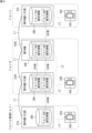
- FIG. 4 is a block diagram for explaining a mechanism for notifying refrigerant leakage.
- FIG. 4 extracts and shows some of the groups A, B, and C included in the air conditioning system 10 .
- Each group A, B, C includes one or more indoor units 21A, 21B1, 21B2, 21C and remote controllers 42A, 42B, 42C. Although only one indoor unit 21A, 21C is shown in group A and group C, a plurality of indoor units may be included.
- the indoor unit 21A and the remote controller 42A included in group A are set for management.
- the indoor unit 21A and the remote controller 42A included in this group A can be installed, for example, in a management room of a building.
- the storage units 29b of the indoor units 21A, 21B1, 21B2, and 21C included in each of the groups A, B, and C store identification information for specifying the groups A, B, and C to which they belong.
- group A identification information is stored in the group A indoor unit 21A.
- Group B identification information is stored in the group B indoor units 21B1 and 21B2.
- Group C identification information is stored in the group C indoor unit 21C.
- the indoor units 21B1 and 21B2 belonging to the same group B share the same identification information.
- the storage units 29b of the indoor units 21B1, 21B2, and 21C of the groups B and C belonging to the management group other than the management group A store the identification information of the group A set for management in addition to the identification information of the groups B and C themselves. is also remembered. Therefore, the identification information of management group A is shared by all the indoor units 21A, 21B1, 21B2, and 21C.
- the model names and device numbers of the indoor units included in each group A, B, and C are used as the identification information for each group A, B, and C. More specifically, in the air conditioning system 10 of the present embodiment, the model names and device numbers of the representative indoor units 21A, 21B1 and 21C are employed as identification information in each of the groups A, B and C.
- a representative indoor unit is an indoor unit generally called a “master unit”, and for example, an indoor unit that supplies power to the remote controller 42 is adopted.
- the device number is a unique number assigned to each indoor unit 21, and corresponds to, for example, a serial number, an address for communication, and the like.
- FIG. 5 is a flowchart showing a processing procedure for sharing identification information of each group among a plurality of indoor units.
- a procedure for sharing identification information among the plurality of indoor units 21B1 and 21B2 in group B in FIG. 4 will be described.
- the indoor unit 21B1 representing the group B transmits its own identification information (model name and device number) to the remote controller 42B (step S11). Transmission of this identification information is based on polling communication.
- the remote controller 42B Upon receiving the identification information, the remote controller 42B transmits the identification information of the representative indoor unit 21B1 to the other indoor units 21B2 in group B (step S12). The transmission of this identification information is also based on polling communication.
- the other indoor unit 21B2 that has received the identification information stores the identification information in the storage unit 29b and shares the identification information of the indoor unit 21B1 (step S13).
- FIG. 6 is a flow chart showing a processing procedure for sharing management group identification information among a plurality of indoor units.
- the notification authority is set for the remote controller 42A of group A.
- the remote controller 42A receives information indicating that the notification authority has been set (setting information) to the indoor unit 21A representing group A (step S22). This transmission is based on polling communication.
- the indoor unit 21A that has received the setting information transmits its own model name and device number, which are identification information of the group A, to the other indoor units 21B1, 21B2, and 21C as the representative of the management group A (step S23). ).
- This transmission is based on broadcast communication. Therefore, the identification information of the indoor unit 21 ⁇ /b>A set for management is also transmitted to the outdoor unit 22 . Handling of the identification information transmitted to the outdoor unit 22 will be described later.
- the other indoor units 21B1, 21B2, and C each store the received identification information of the management group A in the storage unit 29b, and all the indoor units 21A, 21B1, 21B2, and 21C share the identification information (step S24). .
- FIG. 7 is a flow chart showing the control procedure of the indoor unit.
- FIG. 7 shows control procedures for both the indoor unit 21 that has detected refrigerant leakage and the indoor unit 21 that has received information about refrigerant leakage from another indoor unit 21 . This control procedure is performed by the controller 29 of the indoor unit 21 .
- Each indoor unit 21 of the air conditioning system 10 determines whether the leaked refrigerant is detected by the refrigerant sensor 27 (step S31). If the determination in step S31 is affirmative (Yes), the indoor unit 21 broadcasts refrigerant leakage information consisting of the following three pieces of information (a) to (c) to the other indoor units 21.
- Information (a) is a signal generated when refrigerant leaks from the indoor unit 21 and the refrigerant sensor 27 provided in the indoor unit 21 detects the refrigerant, and is also called a leakage flag.
- the indoor units 21 that have received this leakage detection information can recognize that the refrigerant is leaking from other indoor units 21 other than themselves.
- Information (b) is the identification information (model name and device number) of the representative indoor unit 21 shared within the group by the procedure shown in FIG. 5, as described above.
- Information (c) is the identification information (model name and device number) of the representative indoor unit 21 in the management group shared by all the indoor units 21 by the procedure shown in FIG.
- the indoor unit 21 that has detected refrigerant leakage receives an opportunity to communicate with the remote controller 42 by the polling method, it instructs the remote controller 42 to report the refrigerant leakage (step S33).
- each indoor unit 21 of the air conditioning system 10 determines whether or not refrigerant leakage information has been received from another indoor unit 21 (step S41). If the determination in step S41 is affirmative (Yes), the indoor unit 21 compares the identification information of the group to which it belongs and the two transmitted identification information (step S42). If the determination in step S42 is affirmative (Yes), the process proceeds to step S43, and if negative (No), the process returns to step S41.
- step S42 when the indoor unit 21 receives the identification information that matches the identification information of its own group among the refrigerant leakage information, the refrigerant leaks from other indoor units 21 in the same group as the indoor unit 21 concerned.
- the indoor unit 21B1 shown in FIG. 4 transmits refrigerant leakage information (leakage detection information and identification information of groups A and B), and the indoor unit 21B2 receives the information, the indoor unit 21B2 receives information from its own group. B's identification information is compared with the received group A and group B identification information. Since the indoor unit 21B2 receives the identification information that matches the identification information of its own group B, it can recognize that the other indoor unit 21B1 in the same group B is leaking refrigerant.
- step S43 of FIG. 7 the indoor unit 21 instructs the remote controller 42 to notify the refrigerant leakage when an opportunity to communicate with the remote controller 42 is given by the polling method.
- the remote controller 42 in the group can be instructed to notify the refrigerant leakage (step S33, S43). Therefore, after the refrigerant is detected, the indoor unit 21 that becomes able to communicate with the remote controller 42 first can instruct the remote controller 42 to notify the refrigerant leakage, and the notification of the refrigerant leakage by the remote controller 42 is delayed. can be suppressed.
- the indoor unit 21B1 shown in FIG. 4 transmits refrigerant leakage information (leakage detection information and group A and group B identification information) and the indoor unit 21A in the management group A receives it
- the indoor unit 21A compares its own group A identification information with the received group A and group B identification information (step S42). Since the indoor unit 21A has received the identification information that matches the identification information of its own group A, in step S43 of FIG. to notify of refrigerant leakage.
- the manager in the management room such as the building can grasp that the refrigerant is leaking from any of the indoor units 21 in the air conditioning system 10. Appropriate measures can be taken against refrigerant leakage.
- the indoor unit 21A when a plurality of indoor units 21A are included in the management group A, all the indoor units 21A receive identification information that matches the identification information of their own group A.
- the remote controller 42A in the management group A is instructed to report refrigerant leakage. Therefore, after the refrigerant is detected, the indoor unit 21A, which first communicates with the remote controller 42A, can issue a notification instruction, and delay in notification by the remote controller 42A can be suppressed.
- the air-conditioning system 10 of the present embodiment has an interlock function that permits operation of the indoor unit 21 in conjunction with setting notification authority to one of the plurality of remote controllers 42 .
- the outdoor unit 22 receives the identification information transmitted by the broadcast method from the indoor unit 21A representing the management group A in step S23 of FIG. By receiving this identification information, the outdoor unit 22 can recognize that the notification authority has been granted to any remote controller 42, and permits the operation of the indoor unit 21 based on the reception of this identification information. be able to.
- the operation of the indoor unit 21 is permitted in a state in which the notification authority is not set to any of the remote controllers 42, it becomes impossible to notify the manager when refrigerant leakage occurs. It becomes difficult to comply with the JRA standards mentioned above.
- the operation of the indoor unit 21 is not permitted unless the notification authority is set for one of the remote controllers 42. Therefore, the air-conditioning system 10 cannot operate without the notification authority. can be suppressed. Forgetting to set the notification authority can also be suppressed.
- the control device 39 of the outdoor unit 22 can permit operation of the indoor unit 21 by setting notification authority to at least one remote controller 42 in the air conditioning system 10 .
- the interlock function as described above may be provided in the control device 29 of the indoor unit 21.
- the control device 29 of the indoor unit 21 permits the operation of the indoor unit 21 .
- the controller 29 can recognize that the notification authority has been set to the remote controller 42.
- the control device 39 of the outdoor unit 22 has an interlock function, so such inconvenience does not occur.
- the indoor unit 21 of the air conditioner 11 is provided with the refrigerant sensor 27, and notification of refrigerant leakage in the indoor unit 21 has been explained.
- the air conditioning system 10 of the present disclosure detects refrigerant leakage in other equipment through which refrigerant flows, such as an outside air processor or a ventilation device, with a refrigerant sensor, and notifies it with a remote controller. can be anything.
- the display panel 42b of the remote controller 42 is used to notify the refrigerant leakage, but the present invention is not limited to this. , the refrigerant leakage may be notified.
- the alarm device for notifying refrigerant leakage is not limited to the remote controller 42, and may be configured by a device dedicated to notification.
- the identification information of each group A, B, C is not limited to the model name and device number of the representative indoor units 21A, 21B1, 21C, but may be the model name and device number of the indoor units other than the representative.
- the identification information may include only one of the model name and the device number.
- the setting of notification authority for management can be performed for all remote controllers 42 in the air conditioning system 10 . Therefore, it is possible to select one or a plurality of remote controllers 42 from among all the remote controllers 42 to set the notification authority for management. As a result, it is possible to notify only those who need it, such as administrators and people in a specific room, of the refrigerant leakage.
- the interlock function that permits the operation of the indoor unit 21 in conjunction with the setting of the notification authority may function when the notification authority is set for at least one remote controller 42 .
- the air conditioning system 10 of the present embodiment includes a first device (for example, the indoor unit 21A in FIG. 4) and a second device (for example, the indoor units 21B1 and 21B2 in FIG. 4) that are communicably connected to each other and through which refrigerant flows. , or 21C), a first refrigerant sensor 27 that is provided in the first device 21A and detects the refrigerant, and is communicably connected to the first device 21A.
- a first annunciator that notifies leakage for example, the remote controller 42A in FIG. 4) and a control device that controls the first device 21A and the second devices 21B1, 21B2, and 21C (for example, the control device 39 or the control device 29).
- the first annunciator 42A can set the authority to notify refrigerant leakage based on detection of refrigerant received from other than the first refrigerant sensor 27 .
- the device and the alarm installed in the management room are the first device 21A and the first alarm 42A, respectively, so that refrigerant leakage at locations other than the location where the first device 21A is installed Even if it is, it can be notified by the first notification device 42A and can be promptly notified to the administrator or the like.
- the control device 39 or 29 permits the operation of the first device 21A and the second devices 21B1, 21B2, 21C in conjunction with the setting of the authority to the first annunciator 42A. Therefore, since the operation of the first and second devices 21A, 21B1, 21B2, and 21C is permitted in conjunction with the setting of the authority to the first annunciator 42A, the notification authority is set to the first annunciator 42A. The first and second devices 21A, 21B1, 21B2, and 21C cannot be operated until Therefore, it is possible to suppress the operation of the air conditioning system in a state in which the notification authority is not set. Furthermore, forgetting to set the notification authority can be suppressed.
- the air conditioning system 10 includes the second refrigerant sensors (for example, the refrigerant sensors 27 of group B or group C in FIG. 4) provided in the second devices 21B1, 21B2, and 21C to detect the refrigerant,
- a second annunciator for example, the remote controller 42B or 42C in FIG. 4 that is communicatively connected to the second devices 21B1, 21B2, and 21C and notifies refrigerant leakage based on detection of refrigerant by the second refrigerant sensor 27;
- the second annunciators 42B and 42C can set the authority to notify refrigerant leakage based on detection of the refrigerant received from other than the second refrigerant sensor 27 .
- the authority can be selectively set to all or one of the first annunciator 42A and the second annunciators 42B and 42C. Therefore, it is not necessary to set the authority to all of the first and second annunciators 42A, 42B, and 42C, and refrigerant leakage can be notified within a necessary range.
- control devices 39, 29 interlock with the setting of the authority to the first annunciator 42A or the second annunciators 42B, 42C, and 21B2 and 21C are permitted to operate. Therefore, if the authority is set for only one of the first alarm device 42A and the second alarm devices 42B and 42C, the manager can be notified of the refrigerant leakage. 21B2 and 21C can be permitted to operate.
- the third device (for example, the outdoor unit 22 ) connected to the first device 21A and having the compressor 30 is further provided, and the control device 39 is provided in the third device 22 .
- the control device can know that the third device 22 has been changed, and the control device can permit the operation of the first device 21A and the second devices 21B1, 21B2, and 21C other than the third device 22.
- the control device 39 is provided in the third device 22.
- the control device 39 controls the first annunciator 42A. cannot know that notification authority has been set. Therefore, the operation of the first device 21A, the second devices 21B1, 21B2, 21C, and the third device 22 as a whole can be kept stopped.
- the first device 21A and the second devices 21B1, 21B2, and 21C are the first annunciator 42A and the first device 21A.
- the second devices 21B1, 21B2, and 21C transmit the leakage detection information and the identification information to the first device 21A based on detection of the refrigerant by the second refrigerant sensor 27
- the first device 21A instructs the first annunciator 42A to notify the refrigerant leakage based on the reception of the refrigerant detection information and the identification information of the group A to which the first device 21A belongs.
- the first device 21A receives the leakage detection information and the identification information transmitted by the second devices 21B1, 21B2, and 21C, and instructs the first annunciator 42A to notify the refrigerant leakage. Refrigerant leakage from the second device 21B1 can be notified by the device 42A.
- the identification information is information indicating the model name or device number of the first device 21A. According to this configuration, it is possible to set the identification information using the model name or the device number originally assigned to the first device 21A.
- the first device 21A and the second devices 21B1, 21B2, and 21C are communicably connected by a communication method capable of simultaneous communication. According to this configuration, the refrigerant leakage information and the identification information can be quickly transmitted from the second device 21B1 to the first device 21A, and early notification can be realized.
- the first annunciator 42A is a remote controller that operates the first device 21A. Thereby, refrigerant leakage can be notified using the remote controller 42A that operates the first device 21A.
- the interlock function of the air-conditioning system is not limited to the method of interlocking with the setting of the notification authority for the alarm device, and other methods can be adopted.
- the air conditioning system may be configured to permit operation of the indoor units when at least one alarm device is communicably connected.
- the notification authority may not be set for any notification device. Therefore, if the notification authority is not set for any of the alarms, all the alarms will notify the refrigerant leakage based on the reception of the leakage detection information when the refrigerant is detected by any of the refrigerant sensors. good too.
- the alarm device is not limited to a remote controller, and may be a centralized device that centrally controls the outdoor unit and the indoor unit of the air conditioning system.
- Air conditioning system 11 Air conditioner 21A: Indoor unit (first device) 21B1: Indoor unit (second device) 21B2: Indoor unit (second device) 21C: Indoor unit (second device) 22: Outdoor unit (third device) 27: Refrigerant sensor 29: Control device 30: Compressor 39: Control device 42A: Remote controller (first annunciator) 42B: Remote controller (second annunciator) 42C: Remote controller (second alarm)
Landscapes
- Engineering & Computer Science (AREA)
- Chemical & Material Sciences (AREA)
- Combustion & Propulsion (AREA)
- Mechanical Engineering (AREA)
- General Engineering & Computer Science (AREA)
- Human Computer Interaction (AREA)
- Signal Processing (AREA)
- Physics & Mathematics (AREA)
- Fuzzy Systems (AREA)
- Mathematical Physics (AREA)
- Air Conditioning Control Device (AREA)
Abstract
Description
互いに通信可能に接続され、冷媒が流れる第1機器及び第2機器と、
前記第1機器に設けられ冷媒を検出する第1冷媒センサと、
前記第1機器に通信可能に接続され、前記第1冷媒センサによる冷媒の検出に基づいて、冷媒漏洩を報知する第1報知機と、
前記第1機器及び前記第2機器を制御する制御装置と、を備え、
前記第1報知機は、前記第1冷媒センサ以外から受信した冷媒の検出に基づいて冷媒漏洩を報知する権限を設定可能である。
この構成によれば、第1報知機への前記権限の設定に連動して、第1、第2機器の運転が許可されるので、第1報知機に前記権限が設定されるまでは第1、第2機器を運転できなくなる。そのため、前記権限を設定していない状態で空調システムが稼働するのを抑制することができる。
前記第2機器に通信可能に接続され、前記第2冷媒センサによる冷媒の検出に基づいて、冷媒漏洩を報知する第2報知機と、を備え、
前記第2報知機は、前記第2冷媒センサ以外から受信した冷媒の検出に基づいて、冷媒漏洩を報知する権限を設定可能である。
この構成によれば、第1報知機及び第2報知機の全てに又はいずれかに対して選択的に前記権限を設定することができる。そのため、第1、第2報知機の全てに前記権限を設定しなくてもよく、必要な範囲内で冷媒漏洩を報知することができる。
この構成によれば、第1報知機及び第2報知機のうち一方のみに前記権限が設定されれば、管理者に冷媒漏洩を知らせることができるため、第1機器及び第2機器の運転を許可することができる。
前記制御装置が、前記第3機器に設けられる。
この構成によれば、仮に、制御装置が第1機器に設けられていると、第1機器と第3機器との間で通信不良が生じていても、第1報知機に報知権限が付与されたことを制御装置が知ることができ、制御装置は、第3機器以外の第1機器及び第2機器の運転を許可できる。本開示では、制御装置が第3機器に設けられているので、第1機器と第3機器との間で通信不良が生じた場合、制御装置は、第1報知機に報知権限が設定されたことを知ることができない。そのため、第1機器~第3機器全体の運転を停止した状態に維持することができる。
前記第1機器及び前記第2機器が、前記第1報知機と前記第1機器とを含むグループを特定する識別情報を共有しており、
前記第2機器が、前記第2冷媒センサによる冷媒の検出に基づき、漏洩検出情報と前記識別情報とを前記第1機器に送信し、
前記第1機器が、前記漏洩検出情報と、自身が所属するグループの識別情報との受信に基づいて、前記第1報知機に冷媒漏洩の報知を指示する。
この構成によれば、第1機器は、第2機器が送信した漏洩検出情報と識別情報とを受信することよって、第1報知機に冷媒漏洩の報知指示を行い、第1報知機で第2機器の冷媒漏洩を報知することができる。
この構成によれば、第1機器に元々付与されている機種名又は機器番号を利用して識別情報を設定することができる。
この構成によれば、第2機器から第1機器へ冷媒漏洩情報及び識別情報を迅速に伝え、早期の報知を実現することができる。
図1は、本開示の一実施形態に係る空調システムの全体構成図である。
本実施形態の空調システム10は、例えば、ビル等に設置される。空調システム10は、ビルの室内に設置される室内機21と、室外に設置される室外機22とを有する空気調和機11を含む。図1では、第1冷媒系統で動作する空気調和機11Aと、第2冷媒系統で動作する空気調和機11Bとが示されている。
空気調和機11は、冷媒回路23によって冷媒を循環させることにより蒸気圧縮式の冷凍サイクル運転を行う。本実施形態では、冷媒として、可燃性、微燃性、毒性、又は温室効果等の性質を持つ冷媒、例えばR32冷媒が用いられる。
圧縮機30は、低圧のガス冷媒を吸引し高圧のガス冷媒を吐出する。圧縮機30は、インバータ制御によって運転回転数を調整可能なモータを備えている。圧縮機30は、モータがインバータ制御されることによって容量(能力)を変更可能な可変容量型(能力可変型)である。ただし、圧縮機30は一定容量型であってもよい。圧縮機30は複数台設けられていてもよい。この場合、容量可変型の圧縮機と一定容量形の圧縮機とが混在していてもよい。
室内機21は、制御系の構成要素として、制御装置29を備えている。制御装置29は、CPU等の制御部29a、RAM、ROM等の記憶部29bを有するマイクロコンピュータ等により構成されている。制御装置29は、FPGAやASIC等の集積回路を備えたものであってもよい。制御装置29は、前述した室内ファン26及び室内膨張弁24の動作を制御する。制御装置29は、冷媒センサ27から送信された信号を受信する。冷媒センサ27は、冷媒回路23から漏洩した冷媒の検出信号を制御装置29に送信する。
本実施形態では、例えば、冷媒として微燃性を有するR32冷媒が用いられる。そのため、室内機21の冷媒回路23から冷媒が漏洩した場合、できるだけ早くユーザ等に報知することが望まれる。本実施形態では、冷媒センサ27が冷媒を検出したときに、その情報(漏洩検出情報)が室内機21の制御装置29からリモートコントローラ42の制御装置42aに送信され、リモートコントローラ42の表示パネル42bに警報を表示することによって冷媒漏洩が報知される。そのため、部屋を利用するユーザは、冷媒が漏洩したことを認識することができる。
(第1の課題)
日本国内の空気調和機の規格(日本冷凍空調工業会標準規格;JRA規格)では、冷媒漏洩が発生したときに建物の管理者等に報知することが求められている。大規模のビルでは、全ての空気調和機が集中管理装置で一括管理されていることが多いため、いずれかの室内機21で冷媒漏洩が生じた場合にはその情報を集中管理装置で受信し、管理者に報知することができる。しかしながら、中小規模のビル等ではそのような集中管理装置を備えていないことが多いため、冷媒漏洩を管理者等に報知することは困難である。そのため、冷媒漏洩に対する対応が遅くなる可能性がある。
本実施形態の空調システム10のように、複数の室内機21がリモートコントローラ42に対してポーリング方式で通信する場合、室内機21は、冷媒を検出した後すぐにリモートコントローラ42と通信できるとは限らず、順番が回ってきてから通信を行うことになる。そのため、リモートコントローラ42による報知が遅延する可能性がある。
まず、第1の課題に関して、本実施形態の空調システム10では、いずれかのリモートコントローラ42が管理用として設定可能に構成されている。施工業者やサービスマンは、空調システム10を据え付けたとき又は後に、特定のリモートコントローラ42に対して管理用の設定を行うことができる。この管理用の設定は、特定のリモートコントローラ42に対して、当該リモートコントローラ42に接続された室内機21の冷媒センサ27以外から受信した冷媒の検出に基づいて、冷媒漏洩の報知を行う権限(以下、「報知権限」ともいう)を与えるものである。
図4は、冷媒漏洩の報知の仕組みを説明するためのブロック図である。図4には、空調システム10に含まれる一部のグループA,B,Cが抽出して示されている。各グループA,B,Cには、1又は複数の室内機21A,21B1,21B2,21Cとリモートコントローラ42A,42B,42Cとが含まれている。なお、グループAとグループCには、1台の室内機21A,21Cしか示されていないが、複数台の室内機が含まれていてもよい。
図5では、一例として図4のグループBにおける複数台の室内機21B1,21B2で識別情報を共有する手順を説明する。
まず、グループB内において代表となる室内機21B1は、自身の識別情報(機種名および機器番号)をリモートコントローラ42Bに送信する(ステップS11)。この識別情報の送信はポーリング方式の通信による。
一例として、グループAのリモートコントローラ42Aに報知権限を設定する場合について説明する。
施工業者やサービスマンにより、グループAに含まれるリモートコントローラ42Aに対して報知権限を付与する設定が行われると(ステップS21)、リモートコントローラ42Aは、報知権限が設定されたことを示す情報(設定情報)をグループAの代表となる室内機21Aに送信する(ステップS22)。この送信は、ポーリング方式の通信による。
(b)自身のグループの識別情報
(c)管理グループの識別情報
本実施形態の空調システム10は、複数のリモートコントローラ42のいずれかに報知権限を設定した場合に、これに連動して室内機21の運転を許可するインターロック機能を備えている。例えば、室外機22は、図6のステップS23において、管理グループAの代表となる室内機21Aからブロードキャスト方式で送信された識別情報を受信する。室外機22は、この識別情報を受信することによっていずれかのリモートコントローラ42に報知権限が付与されたことを把握することができ、この識別情報の受信に基づいて室内機21の運転を許可することができる。
以上に説明した空調システム10では、空気調和機11の室内機21に冷媒センサ27が設けられ、この室内機21における冷媒漏洩を報知することについて説明した。しかしながら、本開示の空調システム10は、室内機21に加えて又は代えて、冷媒が流れる他の機器、例えば外気処理機又は換気装置における冷媒の漏洩を冷媒センサで検出し、リモートコントローラで報知するものであってもよい。
(1)本実施形態の空調システム10は、互いに通信可能に接続され、冷媒が流れる第1機器(例えば、図4における室内機21A)及び第2機器(例えば、図4における室内機21B1,21B2,又は21C)と、前記第1機器21Aに設けられ冷媒を検出する第1冷媒センサ27と、第1機器21Aに通信可能に接続され、第1冷媒センサ27による冷媒の検出に基づいて、冷媒漏洩を報知する第1報知機(例えば、図4におけるリモートコントローラ42A)と、第1機器21A及び第2機器21B1,21B2,21Cを制御する制御装置(例えば、図3における制御装置39又は制御装置29)を備える。第1報知機42Aは、第1冷媒センサ27以外から受信した冷媒の検出に基づいて冷媒漏洩を報知する権限を設定可能である。
例えば、空調システムのインターロック機能は、報知機に対する報知権限の設定に連動する方法に限らず、他の方法を採用することができる。例えば、空調システムは、少なくとも1つの報知機が通信可能に接続された場合に、室内機の運転を許可するように構成されていてもよい。ただしこの場合、どの報知機にも前記報知権限が設定されないこともあり得る。したがって、どの報知機にも前記報知権限が設定されない場合には、いずれかの冷媒センサで冷媒が検出されたときに、漏洩検出情報の受信に基づいて全ての報知機が冷媒漏洩を報知してもよい。報知機は、リモートコントローラに限らず、空調システムの室外機及び室内機を集中制御する集中機器であってもよい。
11 :空気調和機
21A :室内機(第1機器)
21B1 :室内機(第2機器)
21B2 :室内機(第2機器)
21C :室内機(第2機器)
22 :室外機(第3機器)
27 :冷媒センサ
29 :制御装置
30 :圧縮機
39 :制御装置
42A :リモートコントローラ(第1報知機)
42B :リモートコントローラ(第2報知機)
42C :リモートコントローラ(第2報知機)
Claims (10)
- 互いに通信可能に接続され、冷媒が流れる第1機器(21A)及び第2機器(21B1,21B2,21C)と、
前記第1機器(21A)に設けられ冷媒を検出する第1冷媒センサ(27)と、
前記第1機器(21A)に通信可能に接続され、前記第1冷媒センサ(27)による冷媒の検出に基づいて、冷媒漏洩を報知する第1報知機(42A)と、
前記第1機器(21A)及び前記第2機器(21B1,21B2,21C)を制御する制御装置(39,29)と、を備え、
前記第1報知機(42A)は、前記第1冷媒センサ(27)以外から受信した冷媒の検出に基づいて冷媒漏洩を報知する権限を設定可能である、空調システム。 - 前記制御装置(39,29)は、前記第1報知機(42A)への前記権限の設定に連動して、前記第1機器(21A)及び前記第2機器(21B1,21B2,21C)の運転を許可する、請求項1に記載の空調システム。
- 前記第2機器(21B1,21B2,21C)に設けられ冷媒を検出する第2冷媒センサ(27)と、
前記第2機器(21B1,21B2,21C)に通信可能に接続され、前記第2冷媒センサ(27)による冷媒の検出に基づいて、冷媒漏洩を報知する第2報知機(42B,42C)と、を備え、
前記第2報知機(42B,42C)は、前記第2冷媒センサ(27)以外から受信した冷媒の検出に基づいて、冷媒漏洩を報知する権限を設定可能である、請求項1に記載の空調システム。 - 前記制御装置(39,29)は、前記第1報知機(42A)又は前記第2報知機(42B,42C)への前記権限の設定に連動して、前記第1機器(21A)及び前記第2機器(21B1,21B2,21C)の運転を許可する、請求項3に記載の空調システム。
- 前記第1機器(21A)と接続され、前記冷媒を圧縮する圧縮機(30)を有する第3機器(22)をさらに備え、
前記制御装置(39)が、前記第3機器(22)に設けられる、請求項1~4のいずれか1項に記載の空調システム。 - 前記第1報知機(42A)に前記権限が設定されている場合、
前記第1機器(21A)及び前記第2機器(21B1,21B2,21C)が、前記第1報知機(42A)と前記第1機器(21A)とを含むグループ(A)を特定する識別情報を共有しており、
前記第2機器(21B1,21B2,21C)が、前記第2冷媒センサ(27)による冷媒の検出に基づき、漏洩検出情報と前記識別情報とを前記第1機器(21A)に送信し、
前記第1機器(21A)が、前記漏洩検出情報と、自身が所属するグループ(A)の識別情報との受信に基づいて、前記第1報知機(42A)に冷媒漏洩の報知を指示する、請求項3又は4に記載の空調システム。 - 前記識別情報が、前記第1機器(21A)の機種名又は機器番号を示す情報である、請求項6に記載の空調システム。
- 前記第1機器(21A)と前記第2機器(21B1,21B2,21C)とが一斉通信可能な通信方式で通信可能に接続される、請求項6又は7に記載の空調システム。
- 前記第1報知機(42A)が前記第1機器(21A)を操作するリモートコントローラである、請求項1~8のいずれか1項に記載の空調システム。
- 前記第1機器(21A)及び前記第2機器(21B1,21B2,21C)が、空気調和機の室内機である、請求項1~9のいずれか1項に記載の空調システム。
Priority Applications (3)
| Application Number | Priority Date | Filing Date | Title |
|---|---|---|---|
| EP23756093.3A EP4481287A4 (en) | 2022-02-16 | 2023-01-23 | Air-conditioning system |
| CN202380022114.3A CN118765362A (zh) | 2022-02-16 | 2023-01-23 | 空调系统 |
| US18/798,922 US20240401828A1 (en) | 2022-02-16 | 2024-08-09 | Air conditioning system |
Applications Claiming Priority (2)
| Application Number | Priority Date | Filing Date | Title |
|---|---|---|---|
| JP2022021725A JP7381944B2 (ja) | 2022-02-16 | 2022-02-16 | 空調システム |
| JP2022-021725 | 2022-02-16 |
Related Child Applications (1)
| Application Number | Title | Priority Date | Filing Date |
|---|---|---|---|
| US18/798,922 Continuation US20240401828A1 (en) | 2022-02-16 | 2024-08-09 | Air conditioning system |
Publications (1)
| Publication Number | Publication Date |
|---|---|
| WO2023157565A1 true WO2023157565A1 (ja) | 2023-08-24 |
Family
ID=87578378
Family Applications (1)
| Application Number | Title | Priority Date | Filing Date |
|---|---|---|---|
| PCT/JP2023/001832 Ceased WO2023157565A1 (ja) | 2022-02-16 | 2023-01-23 | 空調システム |
Country Status (5)
| Country | Link |
|---|---|
| US (1) | US20240401828A1 (ja) |
| EP (1) | EP4481287A4 (ja) |
| JP (1) | JP7381944B2 (ja) |
| CN (1) | CN118765362A (ja) |
| WO (1) | WO2023157565A1 (ja) |
Cited By (6)
| Publication number | Priority date | Publication date | Assignee | Title |
|---|---|---|---|---|
| US11927377B2 (en) | 2014-09-26 | 2024-03-12 | Waterfurnace International, Inc. | Air conditioning system with vapor injection compressor |
| US11953239B2 (en) | 2018-08-29 | 2024-04-09 | Waterfurnace International, Inc. | Integrated demand water heating using a capacity modulated heat pump with desuperheater |
| US12169085B2 (en) | 2019-07-15 | 2024-12-17 | Climate Master, Inc. | Air conditioning system with capacity control and controlled hot water generation |
| US12181179B2 (en) | 2016-11-09 | 2024-12-31 | Climate Master, Inc. | Hybrid heat pump with improved dehumidification |
| US12181194B2 (en) | 2016-07-08 | 2024-12-31 | Climate Master, Inc. | Heat pump and water heater |
| US12181189B2 (en) | 2021-11-10 | 2024-12-31 | Climate Master, Inc. | Ceiling-mountable heat pump system |
Citations (4)
| Publication number | Priority date | Publication date | Assignee | Title |
|---|---|---|---|---|
| JP2017036890A (ja) * | 2015-08-11 | 2017-02-16 | ダイキン工業株式会社 | 空調室内機 |
| JP2017053509A (ja) | 2015-09-08 | 2017-03-16 | ジョンソンコントロールズ ヒタチ エア コンディショニング テクノロジー(ホンコン)リミテッド | 空気調和システムおよび空気調和システムの警告報知方法 |
| JP2021129174A (ja) * | 2020-02-12 | 2021-09-02 | ダイキン工業株式会社 | 制御システム、制御方法及びプログラム |
| JP2022170278A (ja) * | 2021-04-28 | 2022-11-10 | ダイキン工業株式会社 | 空調システム |
Family Cites Families (4)
| Publication number | Priority date | Publication date | Assignee | Title |
|---|---|---|---|---|
| JP6613734B2 (ja) * | 2015-09-04 | 2019-12-04 | ダイキン工業株式会社 | 空調システム |
| JPWO2020105117A1 (ja) * | 2018-11-20 | 2021-09-02 | 三菱電機株式会社 | 空気調和装置 |
| JP6678283B1 (ja) * | 2018-11-30 | 2020-04-08 | 日立ジョンソンコントロールズ空調株式会社 | 漏洩検知装置及び漏洩検知システム |
| CN115667821A (zh) * | 2020-05-20 | 2023-01-31 | 大金工业株式会社 | 冷冻循环装置 |
-
2022
- 2022-02-16 JP JP2022021725A patent/JP7381944B2/ja active Active
-
2023
- 2023-01-23 WO PCT/JP2023/001832 patent/WO2023157565A1/ja not_active Ceased
- 2023-01-23 CN CN202380022114.3A patent/CN118765362A/zh active Pending
- 2023-01-23 EP EP23756093.3A patent/EP4481287A4/en active Pending
-
2024
- 2024-08-09 US US18/798,922 patent/US20240401828A1/en active Pending
Patent Citations (4)
| Publication number | Priority date | Publication date | Assignee | Title |
|---|---|---|---|---|
| JP2017036890A (ja) * | 2015-08-11 | 2017-02-16 | ダイキン工業株式会社 | 空調室内機 |
| JP2017053509A (ja) | 2015-09-08 | 2017-03-16 | ジョンソンコントロールズ ヒタチ エア コンディショニング テクノロジー(ホンコン)リミテッド | 空気調和システムおよび空気調和システムの警告報知方法 |
| JP2021129174A (ja) * | 2020-02-12 | 2021-09-02 | ダイキン工業株式会社 | 制御システム、制御方法及びプログラム |
| JP2022170278A (ja) * | 2021-04-28 | 2022-11-10 | ダイキン工業株式会社 | 空調システム |
Non-Patent Citations (1)
| Title |
|---|
| See also references of EP4481287A4 |
Cited By (8)
| Publication number | Priority date | Publication date | Assignee | Title |
|---|---|---|---|---|
| US11927377B2 (en) | 2014-09-26 | 2024-03-12 | Waterfurnace International, Inc. | Air conditioning system with vapor injection compressor |
| US12181194B2 (en) | 2016-07-08 | 2024-12-31 | Climate Master, Inc. | Heat pump and water heater |
| US12181179B2 (en) | 2016-11-09 | 2024-12-31 | Climate Master, Inc. | Hybrid heat pump with improved dehumidification |
| US11953239B2 (en) | 2018-08-29 | 2024-04-09 | Waterfurnace International, Inc. | Integrated demand water heating using a capacity modulated heat pump with desuperheater |
| US12578124B2 (en) | 2018-08-29 | 2026-03-17 | Waterfurnace International, Inc. | Integrated demand water heating using a capacity modulated heat pump with desuperheater |
| US12169085B2 (en) | 2019-07-15 | 2024-12-17 | Climate Master, Inc. | Air conditioning system with capacity control and controlled hot water generation |
| US12173940B2 (en) | 2019-07-15 | 2024-12-24 | Climate Master, Inc. | Air conditioning system with capacity control and controlled hot water generation |
| US12181189B2 (en) | 2021-11-10 | 2024-12-31 | Climate Master, Inc. | Ceiling-mountable heat pump system |
Also Published As
| Publication number | Publication date |
|---|---|
| EP4481287A4 (en) | 2025-06-11 |
| EP4481287A1 (en) | 2024-12-25 |
| JP7381944B2 (ja) | 2023-11-16 |
| CN118765362A (zh) | 2024-10-11 |
| JP2023119089A (ja) | 2023-08-28 |
| US20240401828A1 (en) | 2024-12-05 |
Similar Documents
| Publication | Publication Date | Title |
|---|---|---|
| JP7381944B2 (ja) | 空調システム | |
| JP7817534B2 (ja) | 空調システム | |
| US11927355B2 (en) | Air conditioning and ventilating system | |
| US12416439B2 (en) | Refrigerant cycle apparatus | |
| CN114127480A (zh) | 冷冻循环系统 | |
| WO2020105117A1 (ja) | 空気調和装置 | |
| US11719450B2 (en) | Air-conditioning system | |
| JP2017036890A (ja) | 空調室内機 | |
| JP2016151395A (ja) | 空気調和装置 | |
| US11959675B2 (en) | Air-conditioning apparatus | |
| JPWO2018220810A1 (ja) | 空気調和装置 | |
| JP7177366B2 (ja) | 空気調和装置の据え付け支援システム、据え付け支援装置、及び据え付け支援方法 | |
| JP2016211826A (ja) | 空調換気システム | |
| US11692725B2 (en) | Air-conditioning system with refrigerant leak detection and countermeasures | |
| JP7421131B2 (ja) | 空調システム | |
| JP2008057893A (ja) | 空気調和システム及び空気調和システムの制御装置 | |
| JP7518328B2 (ja) | 空気調和システム | |
| WO2020121514A1 (ja) | 空気調和システムおよびグルーピング設定方法 | |
| JP2019143943A (ja) | 低能力室内機 | |
| WO2022230324A1 (ja) | 空調システム、その運転制御方法、及び空調システムの運転制御装置 | |
| JP2022170267A (ja) | 空調システム | |
| KR20110046044A (ko) | 설비 제어 시스템 | |
| JP2009293824A (ja) | 連絡先報知システム | |
| KR20070058139A (ko) | 멀티 공기조화기 및 그 제어방법 |
Legal Events
| Date | Code | Title | Description |
|---|---|---|---|
| 121 | Ep: the epo has been informed by wipo that ep was designated in this application |
Ref document number: 23756093 Country of ref document: EP Kind code of ref document: A1 |
|
| WWE | Wipo information: entry into national phase |
Ref document number: 202380022114.3 Country of ref document: CN |
|
| WWE | Wipo information: entry into national phase |
Ref document number: 2023756093 Country of ref document: EP |
|
| NENP | Non-entry into the national phase |
Ref country code: DE |
|
| ENP | Entry into the national phase |
Ref document number: 2023756093 Country of ref document: EP Effective date: 20240916 |