WO2023157601A1 - 位置検出装置 - Google Patents
位置検出装置 Download PDFInfo
- Publication number
- WO2023157601A1 WO2023157601A1 PCT/JP2023/002507 JP2023002507W WO2023157601A1 WO 2023157601 A1 WO2023157601 A1 WO 2023157601A1 JP 2023002507 W JP2023002507 W JP 2023002507W WO 2023157601 A1 WO2023157601 A1 WO 2023157601A1
- Authority
- WO
- WIPO (PCT)
- Prior art keywords
- magnetic
- magnetic flux
- flux conducting
- wire
- conducting piece
- Prior art date
- Legal status (The legal status is an assumption and is not a legal conclusion. Google has not performed a legal analysis and makes no representation as to the accuracy of the status listed.)
- Ceased
Links
Images


Classifications
-
- G—PHYSICS
- G01—MEASURING; TESTING
- G01D—MEASURING NOT SPECIALLY ADAPTED FOR A SPECIFIC VARIABLE; ARRANGEMENTS FOR MEASURING TWO OR MORE VARIABLES NOT COVERED IN A SINGLE OTHER SUBCLASS; TARIFF METERING APPARATUS; MEASURING OR TESTING NOT OTHERWISE PROVIDED FOR
- G01D5/00—Mechanical means for transferring the output of a sensing member; Means for converting the output of a sensing member to another variable where the form or nature of the sensing member does not constrain the means for converting; Transducers not specially adapted for a specific variable
- G01D5/12—Mechanical means for transferring the output of a sensing member; Means for converting the output of a sensing member to another variable where the form or nature of the sensing member does not constrain the means for converting; Transducers not specially adapted for a specific variable using electric or magnetic means
- G01D5/244—Mechanical means for transferring the output of a sensing member; Means for converting the output of a sensing member to another variable where the form or nature of the sensing member does not constrain the means for converting; Transducers not specially adapted for a specific variable using electric or magnetic means influencing characteristics of pulses or pulse trains; generating pulses or pulse trains
- G01D5/245—Mechanical means for transferring the output of a sensing member; Means for converting the output of a sensing member to another variable where the form or nature of the sensing member does not constrain the means for converting; Transducers not specially adapted for a specific variable using electric or magnetic means influencing characteristics of pulses or pulse trains; generating pulses or pulse trains using a variable number of pulses in a train
-
- G—PHYSICS
- G01—MEASURING; TESTING
- G01B—MEASURING LENGTH, THICKNESS OR SIMILAR LINEAR DIMENSIONS; MEASURING ANGLES; MEASURING AREAS; MEASURING IRREGULARITIES OF SURFACES OR CONTOURS
- G01B7/00—Measuring arrangements characterised by the use of electric or magnetic techniques
- G01B7/003—Measuring arrangements characterised by the use of electric or magnetic techniques for measuring position, not involving coordinate determination
-
- G—PHYSICS
- G01—MEASURING; TESTING
- G01D—MEASURING NOT SPECIALLY ADAPTED FOR A SPECIFIC VARIABLE; ARRANGEMENTS FOR MEASURING TWO OR MORE VARIABLES NOT COVERED IN A SINGLE OTHER SUBCLASS; TARIFF METERING APPARATUS; MEASURING OR TESTING NOT OTHERWISE PROVIDED FOR
- G01D5/00—Mechanical means for transferring the output of a sensing member; Means for converting the output of a sensing member to another variable where the form or nature of the sensing member does not constrain the means for converting; Transducers not specially adapted for a specific variable
- G01D5/12—Mechanical means for transferring the output of a sensing member; Means for converting the output of a sensing member to another variable where the form or nature of the sensing member does not constrain the means for converting; Transducers not specially adapted for a specific variable using electric or magnetic means
- G01D5/244—Mechanical means for transferring the output of a sensing member; Means for converting the output of a sensing member to another variable where the form or nature of the sensing member does not constrain the means for converting; Transducers not specially adapted for a specific variable using electric or magnetic means influencing characteristics of pulses or pulse trains; generating pulses or pulse trains
- G01D5/245—Mechanical means for transferring the output of a sensing member; Means for converting the output of a sensing member to another variable where the form or nature of the sensing member does not constrain the means for converting; Transducers not specially adapted for a specific variable using electric or magnetic means influencing characteristics of pulses or pulse trains; generating pulses or pulse trains using a variable number of pulses in a train
- G01D5/2454—Encoders incorporating incremental and absolute signals
- G01D5/2455—Encoders incorporating incremental and absolute signals with incremental and absolute tracks on the same encoder
-
- G—PHYSICS
- G01—MEASURING; TESTING
- G01B—MEASURING LENGTH, THICKNESS OR SIMILAR LINEAR DIMENSIONS; MEASURING ANGLES; MEASURING AREAS; MEASURING IRREGULARITIES OF SURFACES OR CONTOURS
- G01B7/00—Measuring arrangements characterised by the use of electric or magnetic techniques
-
- G—PHYSICS
- G01—MEASURING; TESTING
- G01D—MEASURING NOT SPECIALLY ADAPTED FOR A SPECIFIC VARIABLE; ARRANGEMENTS FOR MEASURING TWO OR MORE VARIABLES NOT COVERED IN A SINGLE OTHER SUBCLASS; TARIFF METERING APPARATUS; MEASURING OR TESTING NOT OTHERWISE PROVIDED FOR
- G01D5/00—Mechanical means for transferring the output of a sensing member; Means for converting the output of a sensing member to another variable where the form or nature of the sensing member does not constrain the means for converting; Transducers not specially adapted for a specific variable
- G01D5/12—Mechanical means for transferring the output of a sensing member; Means for converting the output of a sensing member to another variable where the form or nature of the sensing member does not constrain the means for converting; Transducers not specially adapted for a specific variable using electric or magnetic means
- G01D5/14—Mechanical means for transferring the output of a sensing member; Means for converting the output of a sensing member to another variable where the form or nature of the sensing member does not constrain the means for converting; Transducers not specially adapted for a specific variable using electric or magnetic means influencing the magnitude of a current or voltage
- G01D5/142—Mechanical means for transferring the output of a sensing member; Means for converting the output of a sensing member to another variable where the form or nature of the sensing member does not constrain the means for converting; Transducers not specially adapted for a specific variable using electric or magnetic means influencing the magnitude of a current or voltage using Hall-effect devices
- G01D5/145—Mechanical means for transferring the output of a sensing member; Means for converting the output of a sensing member to another variable where the form or nature of the sensing member does not constrain the means for converting; Transducers not specially adapted for a specific variable using electric or magnetic means influencing the magnitude of a current or voltage using Hall-effect devices influenced by the relative movement between the Hall device and magnetic fields
-
- G—PHYSICS
- G01—MEASURING; TESTING
- G01D—MEASURING NOT SPECIALLY ADAPTED FOR A SPECIFIC VARIABLE; ARRANGEMENTS FOR MEASURING TWO OR MORE VARIABLES NOT COVERED IN A SINGLE OTHER SUBCLASS; TARIFF METERING APPARATUS; MEASURING OR TESTING NOT OTHERWISE PROVIDED FOR
- G01D5/00—Mechanical means for transferring the output of a sensing member; Means for converting the output of a sensing member to another variable where the form or nature of the sensing member does not constrain the means for converting; Transducers not specially adapted for a specific variable
- G01D5/12—Mechanical means for transferring the output of a sensing member; Means for converting the output of a sensing member to another variable where the form or nature of the sensing member does not constrain the means for converting; Transducers not specially adapted for a specific variable using electric or magnetic means
- G01D5/14—Mechanical means for transferring the output of a sensing member; Means for converting the output of a sensing member to another variable where the form or nature of the sensing member does not constrain the means for converting; Transducers not specially adapted for a specific variable using electric or magnetic means influencing the magnitude of a current or voltage
- G01D5/20—Mechanical means for transferring the output of a sensing member; Means for converting the output of a sensing member to another variable where the form or nature of the sensing member does not constrain the means for converting; Transducers not specially adapted for a specific variable using electric or magnetic means influencing the magnitude of a current or voltage by varying inductance, e.g. by a movable armature
- G01D5/2006—Mechanical means for transferring the output of a sensing member; Means for converting the output of a sensing member to another variable where the form or nature of the sensing member does not constrain the means for converting; Transducers not specially adapted for a specific variable using electric or magnetic means influencing the magnitude of a current or voltage by varying inductance, e.g. by a movable armature by influencing the self-induction of one or more coils
- G01D5/2033—Mechanical means for transferring the output of a sensing member; Means for converting the output of a sensing member to another variable where the form or nature of the sensing member does not constrain the means for converting; Transducers not specially adapted for a specific variable using electric or magnetic means influencing the magnitude of a current or voltage by varying inductance, e.g. by a movable armature by influencing the self-induction of one or more coils controlling the saturation of a magnetic circuit by means of a movable element, e.g. a magnet
-
- G—PHYSICS
- G01—MEASURING; TESTING
- G01D—MEASURING NOT SPECIALLY ADAPTED FOR A SPECIFIC VARIABLE; ARRANGEMENTS FOR MEASURING TWO OR MORE VARIABLES NOT COVERED IN A SINGLE OTHER SUBCLASS; TARIFF METERING APPARATUS; MEASURING OR TESTING NOT OTHERWISE PROVIDED FOR
- G01D2205/00—Indexing scheme relating to details of means for transferring or converting the output of a sensing member
- G01D2205/20—Detecting rotary movement
- G01D2205/24—Detecting rotary movement using magnetic means not otherwise provided for in this subclass
Definitions
- This invention relates to a position detection device using a power generation sensor.
- a magnetic wire with a large Barkhausen effect is known as a Wiegand wire or pulse wire.
- This magnetic wire has a core and a skin that surrounds the core.
- One of the core and skin is a soft (soft magnetic) layer in which the magnetization direction can be reversed even with a weak magnetic field, and the other of the core and skin is a hard (hard magnetic) layer that does not reverse the magnetization direction unless a strong magnetic field is applied. layer.
- a power generation sensor can be configured by winding a coil around such a magnetic wire.
- the soft layer When the hard layer and the soft layer are magnetized in the same direction along the axial direction of the wire, when the external magnetic field strength in the direction opposite to the magnetization direction increases and reaches a certain magnetic field strength, the soft layer The direction of magnetization is reversed. This reversal of magnetization direction starts at a portion of the magnetic wire and propagates through the wire, causing the magnetization direction of the soft layer to reverse all at once. At this time, the large Barkhausen effect appears and a pulse signal is induced in the coil wound on the magnetic wire. When the above-described external magnetic field strength further increases and reaches a certain magnetic field strength, the magnetization direction of the hard layer is reversed.
- the magnetic field intensity when the magnetization direction of the soft layer is reversed is called “operating magnetic field”
- the magnetic field intensity when the magnetization direction of the hard layer is reversed is called “stabilizing magnetic field”.
- the output voltage obtained from the coil is constant regardless of the change speed of the input magnetic field (external magnetic field), and has hysteresis characteristics for the input magnetic field, so it has the characteristics of no chattering. Therefore, pulse signals generated from the coils are used in position detection devices and the like. Since the output from the coil has electric power, it is possible to configure a power generation type sensor (power generation sensor) that does not require external power supply. That is, peripheral circuits can be operated by the output energy of the coil without supplying external power.
- a power generation type sensor power generation sensor
- the magnetization direction of only the soft layer is reversed from the state in which the magnetization directions of the hard layer and the soft layer match. Even if the magnetization direction of only the soft layer is reversed in a state in which the magnetization directions of the hard layer and the soft layer do not match, no pulse signal is generated or, if generated, the pulse signal is very small.
- a total of two pulse signals, one positive pulse signal and one negative pulse signal, are generated for one cycle.
- a magnet is used as a magnetic field source, and an alternating magnetic field is applied to the power generation sensor by relative motion between the magnet and the power generation sensor. By counting the generated pulse signals, the position can be detected.
- An embodiment of the present invention provides a small position detection device with high position detection resolution.
- a first support a second support that relatively moves with respect to the first support, a power generation sensor arranged on the first support, and the first support.
- a magnetic field generator fixed to the second support such that the relative movement of the two supports causes a plurality of magnetic poles of the same polarity to sequentially enter the detection area along a trajectory passing through the detection area of the power generation sensor. and a source.
- the power generation sensor includes a magnetic wire that exhibits a large Barkhausen effect, a coil wound around the magnetic wire, and magnetically coupled ends of the magnetic wire that face the detection region. and a first magnetic flux conducting piece and a second magnetic flux conducting piece having a.
- the coil of the power generation sensor generates a positive voltage pulse in a first state in which magnetic flux from the magnetic pole of the magnetic field source is conducted from the first magnetic flux conducting piece, and magnetic flux from the magnetic pole of the magnetic field source is generated. generates a negative voltage pulse in a second state conducted from the second magnetic flux conducting piece.
- the magnetic poles of the magnetic field generation source move along the trajectory passing through the detection area of the power generation sensor by moving the second support relative to the first support. Accordingly, when one magnetic pole of the magnetic field source approaches the magnetic flux conducting end of the first magnetic flux conducting piece, the magnetic flux from that magnetic pole enters the first state in which the magnetic flux is conducted from the first magnetic flux conducting piece and is wound around the magnetic wire. A positive voltage pulse is generated from the coil. Also, when the magnetic pole approaches the magnetic flux conducting end of the second magnetic flux conducting piece, a second state in which the magnetic flux from the magnetic pole is conducted from the second magnetic flux conducting piece causes a negative voltage from the coil wound around the flux wire. A pulse is generated.
- a plurality of magnetic poles (magnetic poles of the same polarity) of the magnetic field generation source are preferably arranged so that while one magnetic pole passes through the detection area, other magnetic poles do not enter the detection area.
- the plurality of magnetic poles may be arranged at intervals larger than the axial length of the magnetic wires (for example, intervals of 1.5 times or more the axial length of the magnetic wires) on the track. preferable.
- the magnetic poles of one polarity are arranged so as to face the magnetic flux conducting end and the magnetic poles of the other polarity do not face the magnetic flux conducting end in the detection area. preferably. That is, the magnetic poles facing the first magnetic flux conducting piece and the second magnetic flux conducting piece within the sensing area when the second support moves relative to the first support are all of one polarity (i.e., the same polarity). polarity).
- the sensor element is preferably a sensor other than a power generation sensor.
- a magnetic sensor such as a magnetoresistive element or Hall element can be used.
- the magnetic wire has a core and a skin surrounding it, one of the core and the skin is a soft layer (soft magnetic layer), and the core and the skin are The other is a hard layer (hard magnetic layer).
- said magnetic poles along said tracks in a first set state in which the magnetization directions of both said soft layer and said hard layer are aligned in a first axial direction, which is one of the axial directions of said magnetic wire; said positive voltage pulse is generated from said coil by reversing the magnetization direction of said soft layer in a second axial direction, which is the other axial direction of said magnetic wire, by approaching said magnetic flux conducting end of said first coil. 1 state.
- the magnetization direction of the hard layer is reversed in the second axial direction, and the soft layer and the hard layer are formed. are aligned in the second axial direction, resulting in a second set state.
- the magnetization direction of the soft layer is reversed in the first axial direction to the negative magnetic flux conducting end. voltage pulse is generated from the coil in the second state.
- the magnetic pole can produce a positive voltage pulse by approaching the magnetic flux conducting end of the first magnetic flux conducting piece along its trajectory, and the second set is ready to produce a negative voltage pulse.
- state can be and a first set state in which the magnetic pole can produce a negative voltage pulse by approaching the magnetic flux conducting end of the second magnetic flux conducting piece along its trajectory and is ready to produce a positive voltage pulse. can do.
- two voltage pulses are generated each time a magnetic pole passes near the magnetic flux conducting end of each magnetic flux conducting piece, enabling high-resolution position detection with a compact configuration that does not require a large number of magnetic poles. become.
- the first magnetic flux conducting piece and the second magnetic flux conducting piece are made of soft magnetic parts having substantially the same shape.
- a magnetic field of substantially equal magnitude can be applied to the wire.
- the soft magnetic parts forming the magnetic flux conducting pieces are formed in an I shape perpendicular to the axial direction of the magnetic wire, the magnetic flux conducting end can be arranged at a position distant from the magnetic wire.
- the magnetic poles of the magnetic field source can be arranged to travel along a trajectory remote from the magnetic wires, so that most of the magnetic flux from the magnetic poles is directed to the flux-conducting ends and through the magnetic wires through the magnetic wires.
- the length from the magnetic wire to the magnetic flux conducting end is longer than the length from the magnetic wire to the end opposite to the magnetic flux conducting end. Further, it is preferable that the length from the magnetic wire to the magnetic flux conducting end is 50% or more of the distance between the first magnetic flux conducting piece and the second magnetic flux conducting piece at the coupling position with the magnetic wire. .
- the I-shaped soft magnetic part is magnetically coupled to the magnetic wire at a position offset in one direction with respect to its longitudinal center.
- the distance between the magnetic wire and the magnetic flux conducting end can be increased while miniaturizing the I-shaped soft magnetic part. Therefore, while miniaturizing the power generation sensor (and thus miniaturizing the position detecting device), it is possible to suppress direct entry of the magnetic flux from the magnetic pole into the axial position of the magnetic wire.
- a voltage pulse can be obtained.
- the length of the soft magnetic part from the magnetic wire to the magnetic flux conducting end is set to 50% or more of the distance between the first magnetic flux conducting piece and the second magnetic flux conducting piece at the coupling position from the magnetic wire to the magnetic wire.
- the first magnetic flux conducting piece and the second magnetic flux conducting piece are made of soft magnetic parts having substantially the same shape.
- the soft magnetic parts constituting the first magnetic flux conducting piece and the second magnetic flux conducting piece are respectively connected to both ends of the magnetic wire, and extend from both ends of the magnetic wire in the axial direction of the magnetic wire.
- a pair of axially orthogonal portions extending parallel to each other in orthogonal directions; and extending from tip end portions of the axially orthogonal portions in directions approaching each other along the axial direction, the adjacent ends being opposed to each other with a gap in the axial direction. It is configured in an L-shape or T-shape with a pair of axially parallel portions, the magnetic flux conducting ends facing the sensing region being provided in the axially parallel portions.
- the axially parallel portion extending along the axial direction from the tip portion of the axially perpendicular portion is positioned between the detection region and the magnetic wire, and therefore has the effect of shielding the magnetic wire from the magnetic pole passing through the detection region. have. Therefore, it is possible to more reliably reduce the amount of magnetic flux that directly enters from the magnetic pole to the axially intermediate position of the magnetic wire. Therefore, substantially all of the magnetic flux from the magnetic poles can be conducted to the magnetic flux conducting end facing the detection area in the axially parallel portion, and the magnetic flux can be conducted to the end of the magnetic wire by the magnetic flux conducting piece.
- the size of the power generation sensor can be reduced in the direction orthogonal to the axial direction of the magnetic wire. Accordingly, the size of the position detection device can be reduced. Therefore, it is possible to provide a position detection device having a compact, high-output power generation sensor and high resolution.
- the axial distance of the spacing is 5% to 50% (more preferably 20%) of the axial distance between the pair of axial orthogonal portions at the coupling position with the magnetic wire. ⁇ 40%).
- An excellent magnetic shielding effect can be obtained by setting the distance between the adjacent ends of the axially parallel portions within the above range. Therefore, since the magnetic field in the axial direction of the magnetic wire can be applied over a wide range in the axial direction, the large Barkhausen effect can be sufficiently induced, and the power generation sensor can output a high-output signal.
- the magnetic flux conducting piece has a magnetic field compensating function for compensating the magnetic field from the magnetic field source located in the sensing region, thereby providing a magnetic field between the ends of the magnetic wire in its axial direction.
- the power generation sensor can sufficiently exploit the large Barkhausen effect to generate a high-output pulse signal.
- the magnetic field from the magnetic poles of the magnetic field source can be efficiently directed to the magnetic flux conducting pieces, and each time the magnetic poles approach the magnetic flux conducting ends of the first magnetic flux conducting piece and the second magnetic flux conducting piece, a voltage A pulse can be generated.
- the trajectory of the magnetic pole is a straight trajectory
- the tangent line coincides with the straight trajectory. Therefore, the axial direction of the magnetic wire is parallel to the linear track.
- the perpendicular line may be parallel to the axis of rotation or parallel to the radius of rotation (perpendicular to the axis of rotation).
- the second support rotates relative to the first support about a predetermined rotation axis, and the first support and the second support rotate in the
- the plurality of magnetic poles of the magnetic field generation source are spaced apart in a direction parallel to the rotation axis and are arranged on a circumferential orbit with the rotation axis as a central axis, and each The direction of magnetization of the magnetic poles is parallel to the axis of rotation or parallel to the radius of the circular orbit, and the power generation sensor is placed at a point of contact on a circumference centered on the axis of rotation and having a radius equal to that of the circular orbit.
- supported by the first support with the detection area facing the second support in an arrangement in which the center of the magnetic wire is positioned and the magnetic wire is along a tangent line at the contact point; there is
- the plurality of magnetic poles of the magnetic field generation source move along the circumferential orbit around the rotation axis and are arranged at equal intervals on the circumferential orbit. Therefore, the voltage pulse generated by the magnetic poles passing through the detection area of the power generation sensor can detect the relative rotational position of the second support with respect to the first support.
- the first support and the second support face each other in a direction parallel to the axis of rotation, and the power generation sensor supported by the first support has a detection area facing the second support. Because of the arrangement, it is possible to provide a rotational position detection device with a small size in the radial direction about the rotation axis.
- the magnetization direction of the magnetic poles may be parallel to the axis of rotation or parallel to the radial direction. If radially parallel, the power generation sensor may be positioned to respond to the radially outer magnetic pole or to the radially inner magnetic pole.
- FIGS. 2A and 2B are diagrams for explaining how the position detection device identifies the direction of movement (direction of rotation).
- FIG. 2C and FIG. 2D are diagrams for explaining how to identify the moving direction (rotational direction) in the position detection device.
- 3A and 3B are diagrams for explaining the configuration and operation of a comparative example.
- 3C and 3D are diagrams for explaining the configuration and operation of the comparative example.
- 3E and 3F are diagrams for explaining the configuration and operation of the comparative example.
- FIG. 8A is a diagram for explaining a configuration example of a position detection device according to an embodiment of the present invention, showing a rotary position detection device using a power generation sensor having an L-shaped magnetic flux conducting piece.
- FIG. 8B is a diagram for explaining a configuration example of the position detection device.
- FIG. 8C is a diagram for explaining a configuration example of the position detection device.
- 9A to 9C are diagrams for explaining in detail the operation of the power generation sensor having L-shaped magnetic flux conducting pieces.
- 9D to 9F are diagrams for explaining in detail the operation of the power generation sensor having L-shaped magnetic flux conducting pieces.
- FIG. 10A is a diagram for explaining a configuration example of a position detection device according to an embodiment of the present invention, showing a rotary position detection device using a power generation sensor having an I-shaped magnetic flux conducting piece.
- FIG. 10B is a diagram for explaining a configuration example of the position detection device;
- FIG. 10C is a diagram for explaining a configuration example of the position detection device;
- 11A and 11B are perspective views showing still another specific configuration example of the power generation sensor.
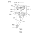
- This position detection device 100 includes a power generation sensor 10 and a magnetic field generation source 20 .
- the power generation sensor 10 is arranged on the first support 31 and supported by the first support 31 .
- the magnetic field source 20 is fixed to the second support 32 .
- the second support 32 moves relative to the first support 31 .
- the magnetic field generating source 20 moves relative to the first support 31 together with the second support 32 .
- the second support 32 rotates about a rotation axis 33 in this example.
- Magnetic field source 20 includes a plurality of magnets M 1 , M 2 positioned away from axis of rotation 33 .
- the plurality of magnets M1 and M2 move along the second support 32 so as to sequentially enter the detection region SR of the power generation sensor 10 by relative motion of the second support 32, specifically rotational motion about the rotation axis 33. 32 is fixed.
- the plurality of magnets M1 and M2 are magnetized so that the magnetic poles P1 and P2 of the same polarity face the power generation sensor 10 in the detection region SR.
- the power generation sensor 10 includes a magnetic wire FE, a coil SP (induction coil) wound around the magnetic wire FE, and a pair of magnetic flux conducting pieces, that is, a first magnetic flux conducting piece FL1 and a second magnetic flux conducting piece FL2.
- the magnetic wire FE is configured to exhibit the large Barkhausen effect.
- the magnetic wire FE has a core and a skin covering it.
- One of the core and skin is a soft layer (soft magnetic layer) in which the magnetization direction can be reversed even with a weak magnetic field, and the other of the core and skin does not reverse the magnetization direction unless a strong magnetic field is applied. It is a hard layer (hard magnetic layer).
- a pair of magnetic flux conducting pieces FL1 and FL2 are magnetically coupled to both ends of the magnetic wire FE.
- Each magnetic flux conducting piece FL1, FL2 has a magnetic flux conducting end 11, 12 facing the sensing area SR.
- the magnetic wire FE sets the axial direction x parallel to the tangent line at a point (contact point) on the circumferential track 21 between the pair of magnetic flux conducting ends 11 and 12, and the perpendicular line to the tangent line at the contact point.
- a center position 15 in the axial direction x (hereinafter referred to as "axis center position 15") is set in the coil SP. generates a positive voltage pulse in a first state conducted from the magnetic flux from the poles P1, P2 of the magnets M1, M2 generates a negative voltage pulse in a second state conducted from the second magnetic flux conducting piece FL2 .
- FIG. 1A shows the first set state, which is a preparatory state for outputting a positive voltage pulse. That is, the magnetization directions of both the soft layer and the hard layer of the magnetic wire FE are aligned in the second axial direction x2, which is one of the axial directions x of the magnetic wire FE.
- the second support member 32 rotates, and the magnetic pole P1 (N pole in the example shown) of the magnet M1 passes through the circumferential orbit 21 to the first magnetic flux conducting piece.
- the detection region SR is a spatial region in which an operating magnetic field and a stabilizing magnetic field are applied to the magnetic wire FE as the magnetic poles P1 and P2 pass.
- the position detection device 100 further includes a sensor element for identifying the direction of rotation.
- Sensor element HS may be a magnetic sensor that detects the magnetic field generated by magnets M1 and M2. Magnetic sensors can be exemplified by magnetoresistive elements and Hall elements.
- the sensor element HS provides an identification signal when the magnetic poles P1, P2 are located on the track 21 between the magnetic flux conducting end 11 of the first magnetic flux conducting piece FL1 and the magnetic flux conducting end 12 of the second magnetic flux conducting piece FL2. are arranged and configured to output. In the illustrated example, the sensor element HS is aligned with the magnetic poles P1, P2 when one of the magnetic poles P1, P2 is positioned on the track 21 between the first magnetic flux conducting piece FL1 and the second magnetic flux conducting piece FL2.
- a magnetic field from the other is detected to generate an identification signal.
- the two magnetic poles P1 and P2 are equally spaced on the circular orbit 21, and the distance between them is greater than the axial length of the magnetic wire FE, so that the two magnetic poles P1 and P2 are simultaneously positioned within the detection region SR. There is no case.
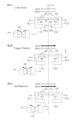
- FIG. 2A to 2D show four states in which pulse voltages are generated.
- FIG. 2A shows a state in which the second support 32 rotates about the rotation axis 33 in the forward rotation direction R1 and the magnetic pole P1 approaches the first magnetic flux conducting piece FL1. state, the coil SP produces a positive pulse.
- FIG. 2B shows a state in which the second support 32 rotates in the forward rotation direction R1 and the magnetic pole P1 approaches the second magnetic flux conducting piece FL2.
- Coil SP generates a negative pulse.
- FIG. 2C shows a state in which the second support 32 rotates in the reverse direction R2 and the magnetic pole P1 approaches the first magnetic flux conducting piece FL1. SP generates a positive pulse.
- FIG. 2D shows a state in which the second support 32 rotates in the reverse direction R2 and the magnetic pole P1 approaches the second magnetic flux conducting piece FL2. SP generates a negative pulse.
- the states of FIGS. 2A and 2C in which a positive pulse is generated are identified by the identification signal output by the sensor element HS. That is, in the state of FIG. 2A, since the magnetic pole P1 located within the detection region SR is not located between the first magnetic flux conducting piece FL1 and the second magnetic flux conducting piece FL2, the sensor element HS is identified. No signal output. On the other hand, in the state of FIG. 2C, since the magnetic pole P1 located within the detection region SR is located between the first magnetic flux conducting piece FL1 and the second magnetic flux conducting piece FL2, the sensor element HS is Outputs an identification signal.
- the states of FIGS. 2B and 2D in which negative pulses are generated are identified by the identification signal output by the sensor element HS. That is, in the state of FIG. 2B, since the magnetic pole P1 located within the detection region SR is located between the first magnetic flux conducting piece FL1 and the second magnetic flux conducting piece FL2, the sensor element HS outputs the identification signal to output In contrast, in the state of FIG. 2D, the magnetic pole P1 located within the detection region SR is not located between the first magnetic flux conducting piece FL1 and the second magnetic flux conducting piece FL2, so the sensor element HS is Does not output an identification signal.
- the rotation direction (forward rotation direction R1 or reverse rotation direction R2) of the second support 32 can be specified by a combination of the positive/negative of the pulse generated by the coil SP and the identification signal output by the sensor element HS. can be done. Therefore, even if the direction of rotation is reversed, the voltage pulse output by the power generation sensor 10 can be used to detect the relative rotational position of the second support 32 with respect to the first support 31 .
- the magnetic wire FE has a second axial direction As a stronger magnetic field is applied to x2, a stabilizing magnetic field is applied to magnetic wire FE and the magnetization direction of the hard layer is also reversed to the second axis direction x2. This sets the condition for generating a positive pulse.
- resin (not shown) for coupling and fixing the magnetic flux conducting pieces FL1, FL2 and the magnetic wire FE is arranged in the wire arrangement portion 13B.
- a coil SP is wound around the magnetic wire FE between the first magnetic flux conducting piece FL1 and the second magnetic flux conducting piece FL2.
- FIG. 6A is a diagram for explaining still another specific configuration example of the power generation sensor 10.
- the power generation sensor 10C includes a magnetic wire FE, and a first magnetic flux conducting piece FL1 and a second magnetic flux conducting piece FL2 magnetically coupled to both ends of the magnetic wire FE.
- a coil SP is wound around the magnetic wire FE between the first magnetic flux conducting piece FL1 and the second magnetic flux conducting piece FL2.
- the first magnetic flux conducting piece FL1 and the second magnetic flux conducting piece FL2 are made of soft magnetic parts having substantially the same shape and size. More specifically, the first magnetic flux conducting piece FL1 and the second magnetic flux conducting piece FL2 are arranged on a plane of symmetry 17 perpendicular to the axial direction x at the axial center position 15 of the magnetic wire FE. symmetrical with respect to the plane).
- the power generation sensor 10C is configured such that the side opposite to the magnetic wire FE with respect to the axially parallel portion 42 is a detection region SR for detecting a magnetic field.
- FIG. 6A magnetic flux conduction when the N pole of the magnet M is arranged near the power generation sensor 10C is represented by a vector. Specifically, the total length of the magnetic wire FE is 11 mm, and the length of the magnet M in the axial direction x of the magnetic wire FE is 10 mm.
- the magnet M (magnetic pole) is arranged such that the center position in the axial direction x is shifted from the axial center position 15 of the magnetic wire FE by 1 mm toward the first magnetic flux conducting piece FL1.
- FIG. 6B shows the magnetic flux density at each position (wire position) in the axial direction x of the magnetic wire FE at this time.
- the wire position is represented by the distance in the axial direction x from the origin, with the end of the magnetic wire FE on the first magnetic flux conducting piece FL1 side as the origin "0" and the end on the second magnetic flux conducting piece FL2 side as "11". be.
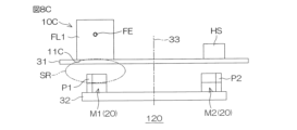
- the first support 31 is, for example, a printed wiring board.
- the magnetic flux conducting ends 11B and 12B (detection area facing surfaces) of the first magnetic flux conducting piece FL1 and the second magnetic flux conducting piece FL2 are joined to one main surface of the first support 31, thereby forming the power generation sensor 10B. are supported on the first support 31 .
- a sensor element HS composed of a magnetic sensor is mounted on the main surface of the first support 31 on which the power generation sensor 10B is mounted.
- the sensor element HS is arranged between the first magnetic flux conducting piece FL1 and the second magnetic flux conducting piece FL2, more specifically, the first magnetic flux conducting piece FL1 and the second magnetic flux conducting piece FL1 and the second magnetic flux conducting piece FL2 with respect to the axial direction x. It is arranged in the middle position of FL2.
- the sensor element HS is arranged in a space where the magnetic flux conducting pieces FL1 and FL2 face each other, and is contained within the width of the magnetic flux conducting pieces FL1 and FL2. As a result, the entire detection section including the power generation sensor 10B and the sensor element HS is substantially within the width of the power generation sensor 10B.
- the second support 32 is a long plate-like body whose longitudinal direction is aligned with the movement direction 50 .
- a plurality of magnets M1 to M5 are arranged at equal intervals in the movement direction 50 (that is, the longitudinal direction of the second support 32) on the main surface of the second support 32 facing the power generation sensor 10B.
- the distance between adjacent magnets M1-M5 in the direction of motion 50 is preferably longer than the length of the magnetic wire FE, preferably about 1.5 times or more the length of the magnetic wire FE.
- the plurality of magnets M1 to M5 are fixed to the second support 32 so that magnetic poles of the same polarity (one of N pole and S pole, eg, N pole) face the power generation sensor 10B.
- each magnet M1 to M5 moves along the linear track 22 parallel to the movement direction 50 and passing through the detection area SR.
- Each magnet M1-M5 thereby faces the magnetic flux conducting end 11B of the first magnetic flux conducting piece FL1 and then the magnetic flux conducting end 12B of the second magnetic flux conducting piece FL2.
- the coil SP of the power generation sensor 10B sequentially generates one positive pulse and one negative pulse according to the principle of operation described with reference to FIGS. 1A to 1E.
- each magnet M1-M5 faces the magnetic flux conducting end 12B of the second magnetic flux conducting piece FL2 and then the second magnetic flux conducting end 12B. It faces the magnetic flux conducting end 11B of one magnetic flux conducting piece FL1.
- the coil SP of the power generation sensor 10B sequentially generates one negative pulse and one positive pulse. Therefore, two voltage pulses are generated each time one of the magnets M1 to M5 passes through the detection region SR of the power generation sensor 10B.
- a sensor element HS consisting of a magnetic sensor generates an identification signal when each of the magnets M1 to M5 faces the power generation sensor 10B on the straight track 22 between the first magnetic flux conducting piece FL1 and the second magnetic flux conducting piece FL2. Generate. Therefore, it has substantially the same function as the sensor element HS described with reference to FIGS. 2A to 2D.
- a power generation sensor 10C including L-shaped magnetic flux conducting pieces FL1 and FL2 shown in FIG. 6A may be used instead of the power generation sensor 10B.
- a sensor element HS consisting of a magnetic sensor may be arranged between the adjacent ends 42a of the axial parallel portions 42 of the pair of magnetic flux conducting pieces FL1 and FL2.
- FIG. 7 shows an example in which the sensor element HS is mounted on the main surface of the first support 31 on the power generation sensor 10B side.
- a sensor element HS may be mounted on the surface.
- the sensor element HS which is a magnetic sensor, does not have to be arranged between the first magnetic flux conducting piece FL1 and the second magnetic flux conducting piece FL2 with respect to the movement direction 50, but may be arranged as illustrated by the two-dot chain line in FIG. can. That is, when a certain magnet (magnet M3 in FIG. 7) is positioned on the linear track 22 between the first magnetic flux conducting piece FL1 and the second magnetic flux conducting piece FL2, it faces another magnet (magnet M4 in FIG. 7).
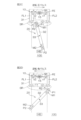
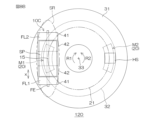
- FIGS. 8A to 8C are diagrams for explaining a configuration example of a position detection device according to an embodiment of the present invention, and show a position detector using a power generation sensor 10C (see FIG. 6A) having an L-shaped magnetic flux conducting piece.
- a detection device 120 is shown.
- This position detection device 120 is a device that detects a rotational position around the rotation axis 33 .
- 8A is a perspective view of the position detection device 120
- FIG. 8B is a plan view of the position detection device 120 viewed along the rotation axis 33
- FIG. 8C is a view of the position detection device 120 viewed from the rotation radial direction parallel to the axial direction x of the magnetic wire FE. It is a side view.
- the position detection device 120 includes a power generation sensor 10C and a magnetic field generation source 20.
- the power generation sensor 10 ⁇ /b>C is arranged on and supported by the first support 31 .
- the magnetic field source 20 is fixed to the second support 32 .
- the second support 32 makes a relative rotational movement about the rotation axis 33 with respect to the first support 31.
- the first support 31 is specifically a printed wiring board and arranged along a plane orthogonal to the rotation axis 33 .
- a power generation sensor 10C is mounted on one main surface of the first support 31 (printed wiring board). More specifically, the wiring in which the axis-parallel portions 42 of the first magnetic flux conducting piece FL1 and the second magnetic flux conducting piece FL2 of the power generation sensor 10C are formed on one main surface of the first support 31 (printed wiring board). It is joined to a pattern (not shown), whereby the power generation sensor 10C is surface-mounted on the first support 31 (printed wiring board).
- the power generation sensor 10C is arranged so that the axial direction x of the magnetic wire FE is aligned with the tangent line at one point (contact point) on the circumference having the rotation axis 33 as the central axis. is arranged to match the contact.
- a plurality of magnets M1 and M2 are fixed to the second support 32 so that the magnetic poles P1 and P2 (N pole in the illustrated example) of the same polarity face the first support 31 (printed wiring board). It is In this embodiment, the magnets M ⁇ b>1 and M ⁇ b>2 are formed in an arc shape along the circumference centered on the rotation axis 33 in plan view along the rotation axis 33 . The distance from the rotation axis 33 to the magnets M1 and M2 (more specifically, the centers of the magnetic poles P1 and P2 facing the first support 31) is the distance from the rotation axis 33 to the axial center position 15 of the magnetic wire FE. equal.
- the magnetic wire FE and the magnets M1 and M2 are positioned on a circle with an equal radius with the rotation axis 33 as the center axis. They have a positional relationship that allows them to face each other.
- the second support 32 is preferably a yoke made of soft magnetic material.
- the axial direction x of the magnetic wire FE is parallel to a tangent line passing through a certain point (contact point) on the circumferential track 21, and the axial center position 15 is a perpendicular line (in this example, a rotating perpendicular line parallel to the axis 33).
- the axial center position 15 of the magnetic wire FE is centered on the rotation axis 33 and is located at a certain point (contact point) on the circumference of the circle having the same radius as the circular orbit 21, and the magnetic wire FE is located at the contact point. along the tangent line at
- the distance in the direction along the rotation axis 33 of the first support 31 and the second support 32 is such that the rotation of the second support 32 allows the magnets M1 and M2 to enter the detection area SR of the power generation sensor 10C. Set to an appropriate value.
- a sensor element HS consisting of a magnetic sensor is further mounted on the main surface on which the power generation sensor 10C is mounted.
- the sensor element HS is positioned symmetrically to the center position of the magnetic wire FE in the axial direction x with respect to the rotation axis 33, that is, faces the axial center position 15 of the magnetic wire FE across the rotation axis 33. placed in position.
- the sensor element HS is positioned between the magnetic poles P1 and P2 when one of the magnetic poles P1 and P2 faces the power generation sensor 10C on the circumferential track 21 between the first magnetic flux conducting piece FL1 and the second magnetic flux conducting piece FL2. and outputs an identification signal.
- the magnetic poles P1 and P2 face the magnetic flux conducting ends 11 and 12 along the radial direction of rotation.
- the magnetic poles P1 and P2 face the magnetic flux conducting ends 11C and 12C along the direction parallel to the rotation axis 33 .
- the magnetic poles P1 and P2 of the magnets M1 and M2 are rotated along the circumferential orbit 21 by rotating in the forward rotation direction R1 about the rotation axis 33.
- One positive pulse and one negative pulse are generated in sequence each time the beam passes through the detection region SR.
- the direction of rotation can be identified by the sensor element HS that outputs an identification signal when the magnets M1 and M2 are on the circumferential track 21 between the first magnetic flux conducting piece FL1 and the second magnetic flux conducting piece FL2. can.
- a device 120 can be provided.
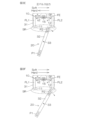
- FIG. 9A to 9F are diagrams for explaining in detail the action of the power generation sensor 10C having the L-shaped magnetic flux conducting pieces FL1 and FL2.
- FIG. 9A (Initial State) shows the first set state, which is a preparatory state for outputting a positive voltage pulse. That is, the magnetization directions of both the soft layer and the hard layer of the magnetic wire FE are aligned in the second axial direction x2.
- the magnetic pole P1 N pole in the illustrated example
- the magnet M1 is the magnetic flux conducting end 11C of the first magnetic flux conducting piece FL1 (detection of the axis-parallel portion 42).
- a second set state is a preparation state for generating a negative voltage pulse.
- the magnet M1 moves further, and the magnetic pole P1 moves toward the magnetic flux conducting end 12C of the second magnetic flux conducting piece FL2 (the surface facing the detection area of the axis-parallel portion 42).
- the magnetic flux from the magnetic pole P1 enters a second state in which the magnetic flux is conducted from the second magnetic flux conducting piece FL2, thereby applying an operating magnetic field in the second axial direction x2 to the magnetic wire FE.
- the large Barkhausen effect is exhibited, and the magnetization direction of the soft layer is reversed to the second axial direction x2. Accordingly, a negative voltage pulse is generated from the coil SP.
- the axially parallel portions 42 of the magnetic flux conducting pieces FL1 and FL2 are positioned between the magnetic wire FE and the axially parallel portions 42 of the magnetic wire FE. is magnetically shielded. Therefore, the magnetic flux from the magnetic pole P1 is attracted to the magnetic flux conducting ends 11C and 12C, which are the faces of the axis-parallel portion 42 facing the detection area, enter the magnetic flux conducting pieces FL1 and FL2 from there, and are guided to the ends of the magnetic wire FE. .
- a magnetic field in the axial direction x can be applied over substantially the entire axial length range of the magnetic wire FE.
- the magnetic flux conducting pieces FL1 and FL2 are configured to have a magnetic field correcting function of correcting the magnetic field formed by the magnetic pole P1 at the magnetic flux conducting ends 11C and 12C to a magnetic field in the axial direction x and applying the magnetic field to the magnetic wire FE. .
- the distance L in the axial direction x of the interval 43 between the proximal ends 42a of the pair of axis-parallel portions 42 is the distance L of the pair of axis-orthogonal portions 41 at the coupling position with the magnetic wire FE.
- this ratio is less than 5%, the large Barkhausen effect can be degraded due to the magnetic path formed through the narrow spacing 43 .
- the ratio is 50% or more, the areas of the magnetic flux conducting ends 11C and 12C (surfaces opposed to the detection regions) are reduced, which may reduce the large Barkhausen effect.
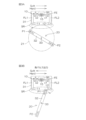
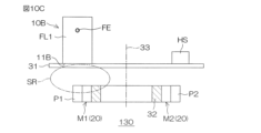
- FIGS. 10A to 10C are diagrams for explaining a configuration example of a position detection device according to an embodiment of the present invention.
- a detection device 130 is shown.
- This position detection device 130 is a device that detects a rotational position around the rotation axis 33 .
- FIG. 10A is a perspective view of the position detection device 130
- FIG. 10B is a plan view of the position detection device 130 as seen along the rotation axis 33
- FIG. It is a side view.
- parts corresponding to parts in FIGS. 8A to 8C are denoted by the same reference numerals.
- the power generation sensor 10B having the I-shaped magnetic flux conducting pieces FL1 and FL2 is used, and the magnetization directions of the magnets M1 and M2 and the shape of the second support 32 are the same as those shown in FIGS. 8A to 8C. different from the form.
- the magnetization direction of the magnets M1 and M2 is the radial direction of rotation about the rotation axis 33 (direction orthogonal to the rotation axis 33).
- Magnetic poles P1 and P2 of the same polarity are arranged outward in the radial direction of rotation.
- Each of the magnets M1 and M2 is formed in an arcuate shape along the circumference with the axis of rotation 33 as the center axis, with the north pole arranged outside and the south pole arranged inside.
- the second support 32 is a ring-shaped soft magnetic yoke, and its outer peripheral surface is coupled to the S poles of the magnets M1 and M2.
- the power generation sensor 10B is arranged with the magnetic wire FE along the tangential line at a point (contact point) on the circumference with the rotation axis 33 as the central axis.
- the axial center position 15 of the magnetic wire FE coincides with the contact.
- the axial center position 15 of the magnetic wire FE moves to one of the outer magnetic poles and the inner magnetic poles of the magnets M1 and M2 as the second support 32 rotates (example shown). It is in a position where it can face the center of the outer magnetic pole).
- the power generation sensor 10B responds to magnetic fields from its opposable magnetic poles P1 and P2.
- the axial direction x of the magnetic wire FE is parallel to a tangent line passing through a certain point (contact point) on the circumferential track 21, and the axial center position 15 is a perpendicular line (in this example, a rotating perpendicular line parallel to the axis 33).
- the axial center position 15 of the magnetic wire FE is centered on the rotation axis 33 and is located at a certain point (contact point) on the circumference of the circle having the same radius as the circular orbit 21, and the magnetic wire FE is located at the contact point. along the tangent line at
- the length H from the magnetic wire FE to the magnetic flux conducting ends 11B, 12B of the I-shaped soft magnetic material parts constituting the magnetic flux conducting pieces FL1, FL2 is , 12B to the end opposite to the length h. That is, the I-shaped soft magnetic part is magnetically coupled to the magnetic wire FE at a position offset in one direction with respect to its longitudinal center. As a result, the distance between the magnetic wire FE and the magnetic flux conducting ends 11B and 12B can be lengthened while miniaturizing the I-shaped soft magnetic part.
- the length H from the magnetic wire FE to the magnetic flux conducting ends 11B and 12B in the I-shaped soft magnetic part is the distance between the first magnetic flux conducting piece FL1 and the second magnetic flux conducting piece FL2 at the coupling position with the magnetic wire FE. It is preferably 50% or more of D. Thereby, most of the magnetic flux from the magnetic poles P1, P2 can be guided to the magnetic flux conducting pieces FL1, FL2 and conducted from the magnetic flux conducting pieces FL1, FL2 to the magnetic wire FE.
- the magnetic flux conducting pieces FL1 and FL2 correct the magnetic field generated by the magnetic pole P1 at the magnetic flux conducting ends 11B and 12B to a magnetic field in the axial direction x, thereby enhancing the magnetic field correction function applied to the magnetic wire FE. can be done. Therefore, it is possible to suppress direct entry of the magnetic flux from the magnetic poles P1 and P2 into the middle position of the magnetic wire FE in the axial direction while miniaturizing the power generation sensor 10B (and thus miniaturizing the position detecting device). A large voltage pulse can be obtained due to the Barkhausen effect. Therefore, it is possible to provide the position detection device 130 that includes the power generation sensor 10B that is compact and capable of high output and that has high resolution.
- the second support 32 is composed of a soft magnetic yoke. need not be a soft magnetic yoke.
- the magnetic field generation source has a plurality of magnets.
- the plurality of protrusions may be used as a plurality of magnetic poles. That is, the number of magnetic poles can be made larger than the number of magnets.
- the axis-perpendicular portion 41 and the axis-parallel portion 42 can be configured as separate parts.
- an L-shape or a T-shaped soft magnetic material component may be formed.
- FIGS. 11A and 11B show power generation sensors 10D and 10E as magnetic flux transmission pieces FL1 and FL2 formed of T-shaped (inverted T-shaped in FIG. 11A and horizontal T-shaped in FIG. 11B) soft magnetic parts as an example.
- an integrated soft magnetic component having the axially perpendicular portion 41 and the axially parallel portion 42 may be configured in a T shape.
- the magnetic field generation source 20 has five magnets M1 to M5, and five magnetic poles of the same polarity can face the power generation sensor 10B.
- three or more magnetic poles of the same polarity may be equally spaced circumferentially about the axis of rotation 33 .
- the arrangement of the sensor element HS (magnetic sensor) in this case is such that when one magnetic pole faces the power generation sensors 10C and 10B on the track between the pair of magnetic flux conducting pieces FL1 and FL2, It should be designed so that it can detect a magnetic field.
- the distance between the magnetic poles on the orbit is longer than the axial length of the magnetic wire FE, preferably 1.5 times or more of the axial length.
- the position detection device provided with one power generation sensor 10 (10A, 10B, 10C) was shown, but two or more power generation sensors may be used.
- the size of the position detection device can be reduced and the cost can be reduced, which is preferable. That is, typically, by adopting a configuration using one power generation sensor, it is possible to realize the most miniaturized high-resolution position detection device.
- the position detection device provided with one sensor element HS was shown in the above embodiment, it may be provided with two or more sensor elements. However, by adopting a configuration including one sensor element HS, it is possible to reduce the size and cost of the position detection device, which is preferable.
Landscapes
- Physics & Mathematics (AREA)
- General Physics & Mathematics (AREA)
- Transmission And Conversion Of Sensor Element Output (AREA)
Abstract
Description
11,11B,11C :磁束伝導端
12,12B,12C :磁束伝導端
13A :貫通孔
13B,13C :ワイヤ配置部
15 :軸中心位置
20 :磁界発生源
21 :円周軌道
22 :直線軌道
31 :第1の支持体
32 :第2の支持体
33 :回転軸線
41 :軸直交部
42 :軸平行部
42a :近接端
50 :運動方向
51 :第1方向
52 :第2方向
100,110,120,130 :位置検出装置
FE :磁性ワイヤ
SP :コイル
SR :検出領域
FL1 :第1磁束伝導片(軟磁性体部品)
FL2 :第2磁束伝導片(軟磁性体部品)
x :軸方向
x1 :第1軸方向
x2 :第2軸方向
HS :センサ要素
D :距離
L :距離
M,M1~M5 :磁石
P1,P2 :磁極
R1 :正転方向
R2 :逆転方向
Claims (10)
- 第1の支持体と、
前記第1の支持体に対して相対移動する第2の支持体と、
前記第1の支持体に配置された発電センサと、
前記第2の支持体の前記相対移動によって前記発電センサの検出領域を通る軌道に沿って前記検出領域に同極性の複数の磁極が順次に進入するように前記第2の支持体に固定された磁界発生源と、を含み、
前記発電センサは、大バルクハウゼン効果を発現する磁性ワイヤと、前記磁性ワイヤに巻回されたコイルと、前記磁性ワイヤの両端部にそれぞれ磁気的に結合され、前記検出領域に対向する磁束伝導端を有する第1磁束伝導片および第2磁束伝導片と、を含み、
前記発電センサの前記コイルは、前記磁界発生源の前記磁極からの磁束が前記第1磁束伝導片から伝導される第1状態で正の電圧パルスを生成し、前記磁界発生源の磁極からの磁束が前記第2磁束伝導片から伝導される第2状態で負の電圧パルスを生成する、位置検出装置。 - 前記第1磁束伝導片の前記磁束伝導端と前記第2磁束伝導片の前記磁束伝導端との間に前記磁界発生源の前記磁極が位置しているかどうかを表す識別信号を出力するセンサ要素をさらに含む、請求項1に記載の位置検出装置。
- 前記磁性ワイヤは、芯部とそれを取り囲む表皮部とを有し、前記芯部および表皮部の一方がソフト層であり、前記芯部および表皮部の他方がハード層であり、
前記ソフト層および前記ハード層の両方の磁化方向が前記磁性ワイヤの軸方向の一方である第1軸方向に揃っている第1セット状態で前記磁極が前記軌道に沿って前記第1磁束伝導片の前記磁束伝導端に接近することによって、前記ソフト層の磁化方向が前記磁性ワイヤの軸方向の他方である第2軸方向に反転して前記正の電圧パルスが前記コイルから生成される前記第1状態となり、
前記第1状態から前記磁極が前記軌道に沿って前記第1磁束伝導片にさらに接近することによって、前記ハード層の磁化方向が前記第2軸方向に反転して、前記ソフト層および前記ハード層の両方の磁化方向が前記第2軸方向に揃った第2セット状態となり、
前記第2セット状態で、前記磁極が前記軌道に沿って前記第2磁束伝導片の前記磁束伝導端に接近することによって、前記ソフト層の磁化方向が前記第1軸方向に反転して前記負の電圧パルスが前記コイルから生成される前記第2状態となり、
前記第2状態から前記磁極が前記軌道に沿って前記第2磁束伝導片の前記磁束伝導端にさらに接近することによって、前記ハード層の磁化方向が前記第1軸方向に反転して、前記ソフト層および前記ハード層の両方の磁化方向が前記第1軸方向に揃った前記第1セット状態となる、請求項1または2に記載の位置検出装置。 - 前記第1磁束伝導片および前記第2磁束伝導片は、実質的に同形状の軟磁性体部品からなり、
前記軟磁性体部品は、前記磁性ワイヤの端部が貫通するワイヤ配置部と、前記ワイヤ配置部から前記磁性ワイヤの軸方向に直交する所定方向に沿って前記磁束伝導端まで延びたI形に構成されている、請求項1~3のいずれか一項に記載の位置検出装置。 - 前記軟磁性体部品は、前記磁性ワイヤから前記磁束伝導端までの長さが、前記磁性ワイヤから前記磁束伝導端とは反対側の端部までの長さよりも長く、かつ前記磁性ワイヤとの結合位置における前記第1磁束伝導片および前記第2磁束伝導片の間の距離の50%以上であるように構成されている、請求項4に記載の位置検出装置。
- 前記第1磁束伝導片および前記第2磁束伝導片は、実質的に同形状の軟磁性体部品からなり、
前記第1磁束伝導片および前記第2磁束伝導片をそれぞれ構成する前記軟磁性体部品は、前記磁性ワイヤの両端部がそれぞれ結合され前記磁性ワイヤの両端部から前記磁性ワイヤの軸方向に直交する方向に互いに平行に延びる一対の軸直交部と、前記軸直交部の先端部から前記軸方向に沿って互いに接近する方向に延び、近接端同士が前記軸方向に間隔を空けて対向する一対の軸平行部とを備えたL形またはT形に構成されており、前記検出領域に対向する前記磁束伝導端を前記軸平行部に設けている、請求項1~3のいずれか一項に記載の位置検出装置。 - 前記間隔の前記軸方向の距離が、前記磁性ワイヤとの結合位置における前記一対の軸直交部の間の前記軸方向の距離の5%~50%である、請求項6に記載の位置検出装置。
- 前記第1磁束伝導片および前記第2磁束伝導片は、前記検出領域に配置される前記磁極が当該第1磁束伝導片および前記第2磁束伝導片の前記磁束伝導端に形成する磁界を前記磁性ワイヤの軸方向の磁界に補正して前記磁性ワイヤに印加するように構成されている、請求項1~7のいずれか一項に記載の位置検出装置。
- 前記第1の支持体に対する前記第2の支持体の相対移動に伴って前記磁界発生源の磁極が前記軌道に沿って前記発電センサの前記検出領域に進入し、
前記発電センサの前記磁性ワイヤの軸方向は、前記軌道上の或る接点を通る接線と平行であり、前記磁性ワイヤの前記軸方向の中心位置は、前記接点において前記接線に立てた垂線上にある、請求項1~8のいずれか一項に記載の位置検出装置。 - 前記第2の支持体は、前記第1の支持体に対して、所定の回転軸線まわりに相対回転し、
前記第1の支持体および前記第2の支持体は、前記回転軸線に平行な方向に間隔を空けて対向しており、
前記磁界発生源の前記複数の磁極は、前記回転軸線を中心軸とする円周軌道上に等間隔に配置されており、かつ各磁極の着磁方向は前記回転軸線と平行または前記円周軌道の半径と平行であり、
前記発電センサは、前記回転軸線を中心とし前記円周軌道と等しい半径の円周上の或る接点に前記磁性ワイヤの中心位置が位置し、かつ当該接点における接線に前記磁性ワイヤが沿う配置で、前記検出領域を前記第2の支持体の側に向けて、前記第1の支持体に支持されている、請求項1~9のいずれか一項に記載の位置検出装置。
Priority Applications (4)
| Application Number | Priority Date | Filing Date | Title |
|---|---|---|---|
| EP23756129.5A EP4481333A4 (en) | 2022-02-16 | 2023-01-26 | POSITION DETECTION DEVICE |
| KR1020247030429A KR20240145025A (ko) | 2022-02-16 | 2023-01-26 | 위치 검출 장치 |
| US18/839,112 US20250389553A1 (en) | 2022-02-16 | 2023-01-26 | Position detection device |
| CN202380021834.8A CN118696213A (zh) | 2022-02-16 | 2023-01-26 | 位置检测装置 |
Applications Claiming Priority (2)
| Application Number | Priority Date | Filing Date | Title |
|---|---|---|---|
| JP2022022294A JP7518112B2 (ja) | 2022-02-16 | 2022-02-16 | 位置検出装置 |
| JP2022-022294 | 2022-02-16 |
Publications (1)
| Publication Number | Publication Date |
|---|---|
| WO2023157601A1 true WO2023157601A1 (ja) | 2023-08-24 |
Family
ID=87578322
Family Applications (1)
| Application Number | Title | Priority Date | Filing Date |
|---|---|---|---|
| PCT/JP2023/002507 Ceased WO2023157601A1 (ja) | 2022-02-16 | 2023-01-26 | 位置検出装置 |
Country Status (7)
| Country | Link |
|---|---|
| US (1) | US20250389553A1 (ja) |
| EP (1) | EP4481333A4 (ja) |
| JP (1) | JP7518112B2 (ja) |
| KR (1) | KR20240145025A (ja) |
| CN (1) | CN118696213A (ja) |
| TW (1) | TW202346800A (ja) |
| WO (1) | WO2023157601A1 (ja) |
Cited By (6)
| Publication number | Priority date | Publication date | Assignee | Title |
|---|---|---|---|---|
| JP7494366B1 (ja) | 2023-09-07 | 2024-06-03 | デルタ電子株式会社 | ロータリーエンコーダ及びそれを含むサーボコントローラ |
| DE102023104327A1 (de) * | 2023-02-22 | 2024-08-22 | Fraba B.V. | Wiegandsensoranordnung |
| WO2024219243A1 (ja) * | 2023-04-17 | 2024-10-24 | オリエンタルモーター株式会社 | 発電センサ |
| WO2025046099A1 (de) * | 2023-09-01 | 2025-03-06 | Fraba B.V. | Wiegandsensor |
| JP7693876B1 (ja) | 2024-03-06 | 2025-06-17 | オリエンタルモーター株式会社 | 運動検出装置 |
| WO2025158490A1 (ja) * | 2024-01-22 | 2025-07-31 | 三菱電機株式会社 | 発電モジュール、発電装置、及び環境センサ |
Families Citing this family (2)
| Publication number | Priority date | Publication date | Assignee | Title |
|---|---|---|---|---|
| JP7791737B2 (ja) * | 2022-02-16 | 2025-12-24 | オリエンタルモーター株式会社 | 発電センサ |
| CN120174530B (zh) * | 2025-04-03 | 2026-02-17 | 浙江奇汇装备制造有限公司 | 一种电子提花机提针位置检测机构 |
Citations (4)
| Publication number | Priority date | Publication date | Assignee | Title |
|---|---|---|---|---|
| JP2000101401A (ja) * | 1998-09-18 | 2000-04-07 | Hirose Electric Co Ltd | パルス信号発生方法および装置 |
| JP2016504906A (ja) * | 2012-12-28 | 2016-02-12 | ラブリオーラ, ドナルド・ピィ, ザ・セカンドLabriola, Donald P., Ii | 多極カウントモータのための一体型多回転絶対位置センサ |
| JP2021021705A (ja) * | 2019-07-30 | 2021-02-18 | オリエンタルモーター株式会社 | 回転検出装置 |
| JP2021021706A (ja) * | 2019-07-30 | 2021-02-18 | オリエンタルモーター株式会社 | 回転検出装置 |
Family Cites Families (4)
| Publication number | Priority date | Publication date | Assignee | Title |
|---|---|---|---|---|
| DE10259223B3 (de) | 2002-11-20 | 2004-02-12 | Mehnert, Walter, Dr. | Positionsdetektor |
| WO2004046735A1 (de) * | 2002-11-20 | 2004-06-03 | Walter Mehnert | Positionsdetektor |
| EP2844955B1 (de) | 2012-04-30 | 2016-05-11 | Fritz Kübler GmbH Zähl-und Sensortechnik | Energieautarker multiturn-drehgeber und verfahren zur ermittlung einer eindeutigen position einer geberwelle mit dem multiturn-drehgeber |
| JP7247318B2 (ja) * | 2018-07-20 | 2023-03-28 | フラバ ベスローテン ヴェンノーツハップ | 回転角度測定システム |
-
2022
- 2022-02-16 JP JP2022022294A patent/JP7518112B2/ja active Active
-
2023
- 2023-01-26 WO PCT/JP2023/002507 patent/WO2023157601A1/ja not_active Ceased
- 2023-01-26 EP EP23756129.5A patent/EP4481333A4/en active Pending
- 2023-01-26 US US18/839,112 patent/US20250389553A1/en active Pending
- 2023-01-26 KR KR1020247030429A patent/KR20240145025A/ko active Pending
- 2023-01-26 CN CN202380021834.8A patent/CN118696213A/zh active Pending
- 2023-02-10 TW TW112104826A patent/TW202346800A/zh unknown
Patent Citations (4)
| Publication number | Priority date | Publication date | Assignee | Title |
|---|---|---|---|---|
| JP2000101401A (ja) * | 1998-09-18 | 2000-04-07 | Hirose Electric Co Ltd | パルス信号発生方法および装置 |
| JP2016504906A (ja) * | 2012-12-28 | 2016-02-12 | ラブリオーラ, ドナルド・ピィ, ザ・セカンドLabriola, Donald P., Ii | 多極カウントモータのための一体型多回転絶対位置センサ |
| JP2021021705A (ja) * | 2019-07-30 | 2021-02-18 | オリエンタルモーター株式会社 | 回転検出装置 |
| JP2021021706A (ja) * | 2019-07-30 | 2021-02-18 | オリエンタルモーター株式会社 | 回転検出装置 |
Non-Patent Citations (1)
| Title |
|---|
| See also references of EP4481333A4 * |
Cited By (9)
| Publication number | Priority date | Publication date | Assignee | Title |
|---|---|---|---|---|
| DE102023104327A1 (de) * | 2023-02-22 | 2024-08-22 | Fraba B.V. | Wiegandsensoranordnung |
| WO2024219243A1 (ja) * | 2023-04-17 | 2024-10-24 | オリエンタルモーター株式会社 | 発電センサ |
| WO2025046099A1 (de) * | 2023-09-01 | 2025-03-06 | Fraba B.V. | Wiegandsensor |
| JP7494366B1 (ja) | 2023-09-07 | 2024-06-03 | デルタ電子株式会社 | ロータリーエンコーダ及びそれを含むサーボコントローラ |
| JP2025038611A (ja) * | 2023-09-07 | 2025-03-19 | デルタ電子株式会社 | ロータリーエンコーダ及びそれを含むサーボコントローラ |
| WO2025158490A1 (ja) * | 2024-01-22 | 2025-07-31 | 三菱電機株式会社 | 発電モジュール、発電装置、及び環境センサ |
| JP7693876B1 (ja) | 2024-03-06 | 2025-06-17 | オリエンタルモーター株式会社 | 運動検出装置 |
| WO2025187643A1 (ja) * | 2024-03-06 | 2025-09-12 | オリエンタルモーター株式会社 | 運動検出装置 |
| JP2025135850A (ja) * | 2024-03-06 | 2025-09-19 | オリエンタルモーター株式会社 | 運動検出装置 |
Also Published As
| Publication number | Publication date |
|---|---|
| EP4481333A1 (en) | 2024-12-25 |
| JP7518112B2 (ja) | 2024-07-17 |
| CN118696213A (zh) | 2024-09-24 |
| US20250389553A1 (en) | 2025-12-25 |
| JP2023119404A (ja) | 2023-08-28 |
| EP4481333A4 (en) | 2026-02-25 |
| KR20240145025A (ko) | 2024-10-04 |
| TW202346800A (zh) | 2023-12-01 |
Similar Documents
| Publication | Publication Date | Title |
|---|---|---|
| WO2023157601A1 (ja) | 位置検出装置 | |
| JP7791737B2 (ja) | 発電センサ | |
| CN101999079B (zh) | 具有铁磁元件的线性分段或转数计数器 | |
| US6885187B2 (en) | Transmitter system for a ferraris motion transmitter | |
| US9052185B2 (en) | Rotation detecting device | |
| US10209096B2 (en) | Rotation detecting device | |
| US4335338A (en) | Linear motor | |
| EP4610600A1 (en) | Multi-rotation angle detection device | |
| WO2022260070A1 (ja) | 運動検出器 | |
| CN117480357A (zh) | 运动检测器 | |
| JP7642183B1 (ja) | 多回転角度検出装置 | |
| JP2022187942A (ja) | 運動検出器 | |
| WO2016031261A1 (ja) | 磁気式位置検出装置 | |
| EP4707747A1 (en) | Motion detection device | |
| TWI921548B (zh) | 運動檢測器 | |
| JP7717112B2 (ja) | 回転検出装置 | |
| WO2025127003A1 (ja) | 回転検出装置 | |
| JP2005121501A (ja) | タンデム型回転検出装置 | |
| JP2006352608A (ja) | 電気パルス発生装置 | |
| JP2022030905A (ja) | ハイブリッド型ステッピングモータ | |
| JPS63127512A (ja) | 着磁装置 |
Legal Events
| Date | Code | Title | Description |
|---|---|---|---|
| 121 | Ep: the epo has been informed by wipo that ep was designated in this application |
Ref document number: 23756129 Country of ref document: EP Kind code of ref document: A1 |
|
| WWE | Wipo information: entry into national phase |
Ref document number: 202380021834.8 Country of ref document: CN |
|
| ENP | Entry into the national phase |
Ref document number: 20247030429 Country of ref document: KR Kind code of ref document: A |
|
| WWE | Wipo information: entry into national phase |
Ref document number: 1020247030429 Country of ref document: KR |
|
| WWE | Wipo information: entry into national phase |
Ref document number: 2023756129 Country of ref document: EP |
|
| NENP | Non-entry into the national phase |
Ref country code: DE |
|
| ENP | Entry into the national phase |
Ref document number: 2023756129 Country of ref document: EP Effective date: 20240916 |