WO2023157616A1 - 位置決め装置、放射線治療装置及び位置決め方法 - Google Patents
位置決め装置、放射線治療装置及び位置決め方法 Download PDFInfo
- Publication number
- WO2023157616A1 WO2023157616A1 PCT/JP2023/002740 JP2023002740W WO2023157616A1 WO 2023157616 A1 WO2023157616 A1 WO 2023157616A1 JP 2023002740 W JP2023002740 W JP 2023002740W WO 2023157616 A1 WO2023157616 A1 WO 2023157616A1
- Authority
- WO
- WIPO (PCT)
- Prior art keywords
- image
- fluoroscopic
- bed
- pseudo
- imaging
- Prior art date
- Legal status (The legal status is an assumption and is not a legal conclusion. Google has not performed a legal analysis and makes no representation as to the accuracy of the status listed.)
- Ceased
Links
Images


Classifications
-
- A—HUMAN NECESSITIES
- A61—MEDICAL OR VETERINARY SCIENCE; HYGIENE
- A61N—ELECTROTHERAPY; MAGNETOTHERAPY; RADIATION THERAPY; ULTRASOUND THERAPY
- A61N5/00—Radiation therapy
- A61N5/10—X-ray therapy; Gamma-ray therapy; Particle-irradiation therapy
- A61N5/1048—Monitoring, verifying, controlling systems and methods
- A61N5/1064—Monitoring, verifying, controlling systems and methods for adjusting radiation treatment in response to monitoring
- A61N5/1069—Target adjustment, e.g. moving the patient support
-
- A—HUMAN NECESSITIES
- A61—MEDICAL OR VETERINARY SCIENCE; HYGIENE
- A61N—ELECTROTHERAPY; MAGNETOTHERAPY; RADIATION THERAPY; ULTRASOUND THERAPY
- A61N5/00—Radiation therapy
- A61N5/10—X-ray therapy; Gamma-ray therapy; Particle-irradiation therapy
-
- A—HUMAN NECESSITIES
- A61—MEDICAL OR VETERINARY SCIENCE; HYGIENE
- A61N—ELECTROTHERAPY; MAGNETOTHERAPY; RADIATION THERAPY; ULTRASOUND THERAPY
- A61N5/00—Radiation therapy
- A61N5/10—X-ray therapy; Gamma-ray therapy; Particle-irradiation therapy
- A61N5/1048—Monitoring, verifying, controlling systems and methods
- A61N5/1049—Monitoring, verifying, controlling systems and methods for verifying the position of the patient with respect to the radiation beam
-
- A—HUMAN NECESSITIES
- A61—MEDICAL OR VETERINARY SCIENCE; HYGIENE
- A61N—ELECTROTHERAPY; MAGNETOTHERAPY; RADIATION THERAPY; ULTRASOUND THERAPY
- A61N5/00—Radiation therapy
- A61N5/10—X-ray therapy; Gamma-ray therapy; Particle-irradiation therapy
- A61N5/1077—Beam delivery systems
- A61N5/1081—Rotating beam systems with a specific mechanical construction, e.g. gantries
-
- A—HUMAN NECESSITIES
- A61—MEDICAL OR VETERINARY SCIENCE; HYGIENE
- A61N—ELECTROTHERAPY; MAGNETOTHERAPY; RADIATION THERAPY; ULTRASOUND THERAPY
- A61N5/00—Radiation therapy
- A61N5/10—X-ray therapy; Gamma-ray therapy; Particle-irradiation therapy
- A61N5/1048—Monitoring, verifying, controlling systems and methods
- A61N5/1049—Monitoring, verifying, controlling systems and methods for verifying the position of the patient with respect to the radiation beam
- A61N2005/1056—Monitoring, verifying, controlling systems and methods for verifying the position of the patient with respect to the radiation beam by projecting a visible image of the treatment field
-
- A—HUMAN NECESSITIES
- A61—MEDICAL OR VETERINARY SCIENCE; HYGIENE
- A61N—ELECTROTHERAPY; MAGNETOTHERAPY; RADIATION THERAPY; ULTRASOUND THERAPY
- A61N5/00—Radiation therapy
- A61N5/10—X-ray therapy; Gamma-ray therapy; Particle-irradiation therapy
- A61N5/1048—Monitoring, verifying, controlling systems and methods
- A61N5/1049—Monitoring, verifying, controlling systems and methods for verifying the position of the patient with respect to the radiation beam
- A61N2005/1061—Monitoring, verifying, controlling systems and methods for verifying the position of the patient with respect to the radiation beam using an x-ray imaging system having a separate imaging source
-
- A—HUMAN NECESSITIES
- A61—MEDICAL OR VETERINARY SCIENCE; HYGIENE
- A61N—ELECTROTHERAPY; MAGNETOTHERAPY; RADIATION THERAPY; ULTRASOUND THERAPY
- A61N5/00—Radiation therapy
- A61N5/10—X-ray therapy; Gamma-ray therapy; Particle-irradiation therapy
- A61N5/1048—Monitoring, verifying, controlling systems and methods
- A61N5/1049—Monitoring, verifying, controlling systems and methods for verifying the position of the patient with respect to the radiation beam
- A61N2005/1061—Monitoring, verifying, controlling systems and methods for verifying the position of the patient with respect to the radiation beam using an x-ray imaging system having a separate imaging source
- A61N2005/1062—Monitoring, verifying, controlling systems and methods for verifying the position of the patient with respect to the radiation beam using an x-ray imaging system having a separate imaging source using virtual X-ray images, e.g. digitally reconstructed radiographs [DRR]
-
- A—HUMAN NECESSITIES
- A61—MEDICAL OR VETERINARY SCIENCE; HYGIENE
- A61N—ELECTROTHERAPY; MAGNETOTHERAPY; RADIATION THERAPY; ULTRASOUND THERAPY
- A61N5/00—Radiation therapy
- A61N5/10—X-ray therapy; Gamma-ray therapy; Particle-irradiation therapy
- A61N5/1048—Monitoring, verifying, controlling systems and methods
- A61N2005/1074—Details of the control system, e.g. user interfaces
-
- A—HUMAN NECESSITIES
- A61—MEDICAL OR VETERINARY SCIENCE; HYGIENE
- A61N—ELECTROTHERAPY; MAGNETOTHERAPY; RADIATION THERAPY; ULTRASOUND THERAPY
- A61N5/00—Radiation therapy
- A61N5/10—X-ray therapy; Gamma-ray therapy; Particle-irradiation therapy
- A61N2005/1085—X-ray therapy; Gamma-ray therapy; Particle-irradiation therapy characterised by the type of particles applied to the patient
- A61N2005/1087—Ions; Protons
-
- A—HUMAN NECESSITIES
- A61—MEDICAL OR VETERINARY SCIENCE; HYGIENE
- A61N—ELECTROTHERAPY; MAGNETOTHERAPY; RADIATION THERAPY; ULTRASOUND THERAPY
- A61N5/00—Radiation therapy
- A61N5/10—X-ray therapy; Gamma-ray therapy; Particle-irradiation therapy
- A61N5/1048—Monitoring, verifying, controlling systems and methods
- A61N5/1064—Monitoring, verifying, controlling systems and methods for adjusting radiation treatment in response to monitoring
Definitions
- the present disclosure relates to a positioning device, radiation therapy device and positioning method.
- Radiation therapy which irradiates patients with radiation, is known as one of the cancer treatment methods. Radiation used in radiotherapy is broadly classified into non-charged particle beams such as X-rays and gamma rays and charged particle beams such as proton beams and carbon beams. Radiation therapy using the latter charged particle beam is generally called particle beam therapy.
- a charged particle beam can form a dose distribution (black curve) having an energy loss peak at a specific depth. Therefore, by aligning the peak of the energy loss of the charged particle beam with the position of the tumor, it is possible to significantly reduce the dose of the charged particle beam irradiated to the normal tissue located deeper than the tumor.
- patient positioning In order to achieve accurate delivery of radiation to the tumor, it is necessary to align the patient with the same planned position determined by the previously created treatment plan. This positioning of the patient is referred to as patient positioning.
- a patient lying on a bed is captured from two different directions using two sets of X-ray tubes and a flat panel detector (FPD).
- FPD flat panel detector
- DR Digital Radiography
- a fluoroscopic X-ray image taken of the patient during radiotherapy is compared with a pseudo-fluoroscopic X-ray image created from the CT (Computed Tomography) image used to create the treatment plan, and a bone-like image is obtained.
- the patient is positioned so that the position of the structure to be positioned matches between the fluoroscopic X-ray image and the pseudo-fluoroscopic X-ray image.
- structures other than the structure to be positioned such as the patient's fixture and soft tissue
- the fluoroscopic X-ray image changes from the time of treatment planning.
- the structures imaged in the fluoroscopic and pseudo-fluoroscopic X-ray images do not match throughout the images.
- positioning of the patient is performed using a region of interest (ROI) set as a region in which the structure to be positioned exists on the fluoroscopic X-ray image.
- ROI region of interest
- the setting of the region of interest is usually performed by drawing the region of interest on the image by a user who is a medical professional.
- the three axes that define the amount of translation coincide with the movement axes of the bed for placing the patient in the planned position
- the x-axis is the direction from right to left when viewed from the patient lying supine on the bed (Right- Left direction: RL direction)
- the y-axis is in the direction from the feet to the head (Superior-Inferior direction: SI direction)
- the z-axis is in the direction from the back to the abdomen (Anterior-Posterior: AP direction).
- Patent Documents 1 and 2 disclose techniques for reaching the optimal value with a smaller number of iterations.
- a one-dimensional optimization process is added to the direction along the imaging axis along which the fluoroscopic X-ray image is captured. Reduction of the number of calculations to repeat the optimization process in the calculation is attempted.
- Patent Document 3 the optimization of the amount of translation in the direction along the imaging axis is evaluated only in one direction perpendicular to the fluoroscopic imaging axis, thereby reducing the number of fluoroscopic X-ray images, A technique for shortening the time required for positioning is disclosed.
- An object of the present disclosure is to provide a positioning device, a radiotherapy device, and a positioning method that can further reduce calculation time.
- a positioning device is a positioning device that controls the position of a bed on which a subject is mounted, and the positioning device transmits light from a light source to each of a plurality of imaging axes via the subject on a detection plane.
- an image acquisition unit that acquires a plurality of fluoroscopic images of the subject by detecting with a creation unit that creates, for each of the plurality of imaging axes, a pseudo perspective image obtained by projecting the three-dimensional perspective image of the subject onto a detection plane for the imaging axis;
- a correction axis obtained by correcting the imaging axis is obtained based on the amount of deviation between the fluoroscopic image and the pseudo-fluoroscopic image corresponding to the distance from the intersection of the plurality of imaging axes to the midpoint of the common perpendicular of each correction axis. as a bed movement amount for moving the bed.
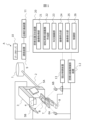
- FIG. 1 is a diagram showing the overall configuration of a particle beam therapy system according to an embodiment of the present disclosure
- FIG. 4 is a flowchart for explaining an example of patient positioning processing
- FIG. 10 is a diagram for explaining processing for obtaining a correction axis from a two-dimensional movement amount
- FIG. 10 is a diagram for explaining processing for obtaining a three-dimensional movement amount from a correction axis
- 5 is an enlarged view of the common perpendicular shown in FIG. 4;
- FIG. 10 is a diagram for explaining processing for obtaining a correction axis from a two-dimensional movement amount
- FIG. 10 is a diagram for explaining processing for obtaining a three-dimensional movement amount from a correction axis
- 5 is an enlarged view of the common perpendicular shown in FIG. 4;
- FIG. 4 is a flowchart for explaining an example of patient positioning processing
- FIG. 10 is a diagram for explaining processing for obtaining a correction axis from a two-dimensional movement amount
- FIG. 1 is a diagram showing the overall configuration of a particle beam therapy system according to one embodiment of the present disclosure.
- a particle beam therapy system A shown in FIG. 1 is a radiotherapy apparatus having a device group for irradiating a particle beam to a patient B who is a subject.
- the particle beam therapy system A includes an accelerator 1, a beam transport device 2, a gantry 3, an irradiation nozzle 4, FPDs 5A and 5B, X-ray tubes 6A and 6B, a bed 7, a robot arm 8, and a communication device. 9 , a data server 10 , a treatment planning device 11 , a fluoroscopic X-ray imaging device 12 , a bed control device 13 and a patient positioning device 20 .
- the accelerator 1 is a particle beam generator that generates a particle beam to irradiate patient B, and accelerates the particle beam until it reaches an energy suitable for treating patient B and outputs it.
- a beam transport device 2 transports the particle beam output from the accelerator 1 to the gantry 3 .
- the type of particle beam is not particularly limited, and examples thereof include proton beams and carbon beams.
- the gantry 3 and the irradiation nozzle 4 are irradiation devices that irradiate the patient B with the particle beam transported from the accelerator 1.
- Gantry 3 adjusts the irradiation angle at which patient B is irradiated with the particle beam transported from accelerator 1 .
- the gantry 3 has a rotating mechanism capable of rotating 360 degrees around the patient B, and adjusts the irradiation angle by rotating.
- the irradiation nozzle 4 is provided on the gantry 3 and irradiates the patient B with the particle beam transported to the gantry 3 .
- the irradiation nozzle 4 may incorporate a mechanism for adjusting the shape of the particle beam to match the shape of the affected area of the patient.
- the FPDs 5A and 5B and the X-ray tubes 6A and 6B constitute an imaging system for fluoroscopic imaging of the patient B.
- the FPDs 5A and 5B are flat panel detectors that image the patient B by detecting X-rays, which are light for imaging, on their detection surfaces.
- the X-ray tubes 6A and 6B are light sources that output X-rays.
- the FPD 5A and the X-ray tube 6A are arranged facing each other so that the X-rays output from the X-ray tube 6A are detected by the FPD 5A through the patient B, and the FPD 5B and the X-ray tube 6B are arranged opposite to each other so that the X-rays output from are transmitted through the patient B and detected by the FPD 5B.
- An axis connecting the center of the FPD 5A and the X-ray tube 6A and an axis connecting the center of the FPD 5B and the X-ray tube 6B are two imaging axes for imaging the patient B.
- the two imaging axes are preferably orthogonal to each other, but need not be orthogonal to each other.
- the particle beam therapy system A may include three or more FPDs and three or more X-ray tubes. In this case, there are three or more imaging axes.
- the bed 7 is a table on which the patient B is placed when the patient B is irradiated with the particle beam.
- a robot arm 8 is a device for moving the bed 7 . Specifically, the robot arm 8 translates the bed 7 in a plurality of translational directions along each of a plurality of movement axes and rotates in a plurality of rotational directions about a plurality of rotational axes. Move and do.
- the movement axis and the rotation axis are the same, and there are three movement axes (rotation axes).
- each movement axis is in the direction from right to left (RL direction) when viewed from the patient B lying face up on the bed 7, the direction from the feet to the head of the patient B (SI direction), and the direction from the back to the abdomen. (AP direction).
- the communication device 9 communicably connects the data server 10, the treatment planning device 11 and the patient positioning device 20 to each other.
- the data server 10 is a storage device that stores various information related to particle beam therapy for patient B.
- the data server 10 stores, for example, a three-dimensional fluoroscopic image of the patient B and treatment plan information indicating a treatment plan for the patient B.
- the 3D fluoroscopic image contains information that describes the shape and electron density of the patient in voxels.
- the three-dimensional fluoroscopic image is, for example, a computed tomography (CT) image, and is generated in advance (before creating treatment plan information for patient B).
- Treatment plan information is generated based on the three-dimensional fluoroscopic image.
- the treatment plan information also includes planned arrangement information indicating planned arrangement, which is the arrangement of the patient B during treatment.
- the placement of the patient B indicates the position and angle (orientation) of the patient B, and is determined by the position and angle of the bed 7 .
- the treatment planning device 11 creates a treatment plan for the patient B based on the three-dimensional fluoroscopic image stored in the data server 10, and stores treatment plan information indicating the treatment plan in the data server 10.
- the fluoroscopic X-ray imaging apparatus 12 controls the FPD 5A and the X-ray tube 6A, and the FPD 5B and the X-ray tube 6B, respectively, and acquires a plurality of fluoroscopic X-ray images of the patient B photographed from different angles as fluoroscopic images. and transmits the acquired fluoroscopic X-ray image to the patient positioning device 20 .
- the bed control device 13 adjusts the placement of the patient B by controlling the robot arm 8 to adjust the placement of the bed 7 .
- the patient positioning device 20 positions the patient B based on the three-dimensional fluoroscopic image and treatment plan information stored in the data server 10 and the fluoroscopic X-ray image acquired by the fluoroscopic X-ray imaging device 12. Execute.
- the patient B positioning process is a process of placing the patient B placed on the bed 7 in the same position as the planned position shown in the treatment plan information before starting particle beam therapy for the patient B.
- the patient positioning device 20 controls the robot arm 8 via the bed control device 13 to adjust the position and angle of the bed 7, thereby placing the patient B in the same placement as the planned placement.
- particle beam therapy will actually be performed on patient B.
- a particle beam accelerated by an accelerator 1 to an energy suitable for treatment is transported to a gantry 3 via a beam transporter 2 .
- the particle beam is deflected in an appropriate direction by the gantry 3, passes through the irradiation nozzle 4, and is irradiated to the patient B's affected area.
- the patient positioning device 20 will be described in more detail below.
- the patient positioning apparatus 20 includes an image acquisition unit 21, a pseudo-fluoroscopic X-ray image generation unit 22, an ROI drawing unit 23, an image matching unit 24, an image display unit 25, and a control unit 26. and
- the image acquisition unit 21 acquires a three-dimensional fluoroscopic image from the data server 10 via the communication device 9 and acquires a fluoroscopic X-ray image from the fluoroscopic X-ray imaging device 12 .
- the pseudo-fluoroscopic X-ray image creating unit 22 projects the three-dimensional fluoroscopic images acquired by the image acquiring unit 21 onto a plurality of planes corresponding to the respective imaging axes for capturing the fluoroscopic X-ray images, forming a plurality of pseudo-fluoroscopic images.
- a creation unit that creates a plurality of pseudo-fluoroscopic X-ray images, which are images.
- the pseudo-fluoroscopic X-ray image creating unit 22 creates a pseudo-fluoroscopic X-ray image by arranging and projecting the three-dimensional image of the patient B in the same virtual space as the imaging system that generated the fluoroscopic X-ray image. .
- the plane corresponding to the imaging axis is, for example, the detection plane of the FPD corresponding to the imaging axis, that is, the plane substantially perpendicular to the imaging axis.
- the ROI drawing unit 23 identifies the ROI, which is the region of interest used for patient positioning in the pseudo-fluoroscopic X-ray image. Specifically, the ROI drawing unit 23 specifies the ROI by displaying the pseudo-fluoroscopic X-ray image and allowing the user to draw the ROI on the pseudo-fluoroscopic X-ray image.
- the ROI is drawn to include the structure to be positioned, eg bone.
- the image matching unit 24 is a calculation processing unit that calculates the bed movement amount for moving the bed 7 based on the fluoroscopic X-ray image and the pseudo-fluoroscopic X-ray image.
- the image matching unit 24 may calculate the bed movement amount based on the fluoroscopic X-ray image and the pseudo-fluoroscopic X-ray image in the ROI.
- the bed movement amount includes movement amounts in each of a plurality of translational directions.
- the image display unit 25 is a display unit that displays various information and images.
- the image display unit 25 displays a fluoroscopic X-ray image, a pseudo-fluoroscopic X-ray image, an ROI image indicating an ROI area, and the like.
- the control unit 26 adjusts the placement of the patient B by controlling the bed control device 13 and moving the bed 7 based on the bed movement amount calculated by the image matching unit 24 .
- the patient positioning device 20 having the above functions can be realized by an information processing device capable of various information processing such as a computer device.
- An information processing device has, for example, an arithmetic element, a storage medium, and a communication interface, and, if necessary, an input unit such as a mouse and a keyboard, and a display unit such as a display.
- Arithmetic elements are, for example, processors such as CPUs (Central Processing Units) and FPGAs (Field-Programmable Gate Arrays).
- Storage media include, for example, magnetic storage media such as HDDs (Hard Disk Drives), semiconductor storage media such as RAMs (Random Access Memory), ROMs (Read Only Memory) and SSDs (Solid State Drives).
- magnetic storage media such as HDDs (Hard Disk Drives), semiconductor storage media such as RAMs (Random Access Memory), ROMs (Read Only Memory) and SSDs (Solid State Drives).
- RAMs Random Access Memory
- ROMs Read Only Memory
- SSDs Solid State Drives
- a combination of an optical disc such as a DVD (Digital Versatile Disk) and an optical disc drive may be used.
- other high cost storage media such as magnetic tape media may be used as storage media.
- Programs such as firmware are stored in the storage medium.
- the arithmetic element reads out the program from the storage medium and executes it, thereby implementing the units 21 to 27 of the patient positioning device 20 and performing the entire series of controls. executed.
- the storage medium stores data required for each process of the patient positioning device 20 and the like.
- the patient positioning device 20 of this embodiment may be configured by so-called cloud computing, in which a plurality of information processing devices are configured to be able to communicate via a communication network.
- FIG. 1 The patient positioning processing by the patient positioning device 20 will be described in more detail below using FIGS. 2 to 5.
- FIG. 1 is a diagrammatic representation of the patient positioning device 20.
- FIG. 2 is a flowchart for explaining an example of patient positioning processing.
- a set-up position is a position for placing the patient B in the same arrangement as the planned arrangement.
- the position of the body surface of the patient B on the bed 7 is measured using an infrared laser installed in the treatment room, and the patient B is placed in the set-up position on the bed 7 based on the position.
- the control unit 26 first acquires treatment plan information from the data server 10, and controls the robot arm 8 via the bed control device 13 based on the planned arrangement information included in the treatment plan information. Then, the bed 7 on which the patient B is placed is moved so that the placement of the patient B becomes the planned placement indicated by the planned placement information (step S100). At this time, the positioning target structure of the patient B placed on the bed 7 is included in the X-ray irradiation area formed by the FPDs 5A and 5B and the X-ray tubes 6A and 6B.
- the image acquiring unit 21 acquires a plurality of fluoroscopic X-ray images obtained by imaging the patient B from a plurality of mutually different directions via the fluoroscopic X-ray imaging device 12 (step S101).
- the image acquisition unit 21 acquires two fluoroscopic X-ray images taken from two directions along two imaging axes.
- the pseudo-fluoroscopic X-ray image creating unit 22 acquires a three-dimensional fluoroscopic image from the data server 10, and creates two pseudo-fluoroscopic X-ray images corresponding to the two imaging axes from the three-dimensional fluoroscopic image (step S102).
- the image matching unit 24 calculates the amount of deviation in the two-dimensional direction between the fluoroscopic X-ray image and the pseudo-fluoroscopic X-ray image corresponding to the imaging axis, on the detection plane of the FPD corresponding to the imaging axis. It is calculated as a movement amount (step S103).
- a calculation method for calculating the amount of image deviation is a method of scanning a pseudo-fluoroscopic X-ray image in the horizontal and vertical directions with respect to the fluoroscopic X-ray image and searching for the position where the similarity between these images is the highest.
- this method requires sequential calculation of the similarity, resulting in a large amount of calculation. Therefore, in this embodiment, a calculation method using a POC (Phase-Only Correlation method) method, which is known as a method capable of high-speed image matching, will be described.
- POC Phase-Only Correlation method
- the POC method is a method of matching (aligning) images using only the phase components obtained from the two-dimensional discrete Fourier transform of the images, and is characterized by being resistant to disturbances such as changes in image brightness.
- the POC method is different from the method of performing matching based on image feature points such as edges and corners, and can perform accurate alignment even for images that do not have clear features.
- the image matching unit 24 uses a POC function (phase-only correlation function) used as an evaluation index for matching by the POC method to determine the amount of deviation between the fluoroscopic X-ray image and the pseudo-fluoroscopic X-ray image. A two-dimensional movement amount is calculated.
- POC function phase-only correlation function
- Images f(n 1 , n 2 ) and g(n 1 , n 2 ) are both N 1 ⁇ N 2 pixel images.
- a two-dimensional discrete Fourier transform (DFT) of images f(n 1 , n 2 ) and g(n 1 , n 2 ) is represented by the following equations (1) and (2).
- a F (k 1 , k 2 ) and AG (k 1 , k 2 ) are amplitude spectra
- ⁇ F (k 1 , k 2 ) and ⁇ G (k 1 , k 2 ) are phase spectra.
- the normalized mutual power spectra of the images f(n 1 ,n 2 ) and g(n 1 ,n 2 ) are the functions F(k 1 ,k 2 ) and G(k 1 ,k 2 ) after the Fourier transform. ), it is represented by the following equation (3). here, denotes the complex conjugate of G(k 1 ,k 2 ). Also, ⁇ F (k 1 , k 2 ) ⁇ G (k 1 , k 2 ) ⁇ is the phase difference spectrum of images f(n 1 , n 2 ) and g(n 1 , n 2 ).
- the POC function r(n 1 , n 2 ) is defined by the following equation (4) as a two-dimensional Inverse Discrete Fourier Transform (IDFT) of the normalized mutual power spectrum.
- IDFT Inverse Discrete Fourier Transform
- the POC function has a sharp peak, called a correlation peak, when the images of interest f(n 1 ,n 2 ) and g(n 1 ,n 2 ) are similar to each other.
- the height of the correlation peak represents the linearity of the phase difference spectra of the images f(n 1 , n 2 ) and g(n 1 , n 2 ) with respect to frequency.
- the correlation peak has a height of 1.
- the height of the correlation peak is useful as a measure of image similarity, and is used in image matching and the like.
- the coordinates of the correlation peak represent the relative displacement amount of the images.
- the image collating unit 24 uses a fluoroscopic X-ray image and a pseudo-fluoroscopic X-ray image as images f(n 1 , n 2 ) and g(n 1 , n 2 ).
- a two-dimensional movement amount is calculated using an image obtained by multiplying an image by a window function.
- the window function is, for example, a two-dimensional Hanning window w(n 1 , n 2 ) represented by Equation (5).
- the image matching unit 24 uses the POC method as described above to determine, for each imaging axis, the position of the correlation peak of the phase-only correlation function calculated from the fluoroscopic X-ray image and the pseudo-fluoroscopic X-ray image, and the origin.
- a shift amount in a dimension direction is calculated as a two-dimensional movement amount.
- the image matching unit 24 executes a three-dimensional movement amount calculation process for calculating a three-dimensional movement amount as a bed movement amount for moving the bed 7 based on the two-dimensional movement amount of each imaging axis (step S104).
- the image matching unit 24 first calculates, for each imaging axis, based on the two-dimensional movement amount, which is the amount of deviation between the fluoroscopic X-ray image and the pseudo-fluoroscopic X-ray image corresponding to the imaging axis. , to obtain a corrected axis obtained by correcting the photographing axis. Then, the image matching unit 24 calculates the movement amount from the intersection of each imaging axis to the midpoint of the common perpendicular line of each correction axis as the three-dimensional movement amount, which is the bed movement amount.
- FIG. 3 to 5 are diagrams for explaining the three-dimensional movement amount calculation process in more detail.
- FIG. 3 is a diagram for explaining the process of obtaining the correction axis from the two-dimensional movement amount
- FIG. 4 is a diagram for explaining the process of obtaining the three-dimensional movement amount from the correction axis.
- 5 is an enlarged view of the common perpendicular shown in FIG. 4; FIG. It is assumed that the distortion of the fluoroscopic X-ray image due to the arrangement angles of the FPDs 5A and 5B has been removed in advance by distortion correction. Distortion correction may be performed, for example, by an imaging device that captures a fluoroscopic X-ray image, or may be performed by the patient positioning device 20 . Further, even if distortion correction is not performed, it is possible to perform the following three-dimensional movement amount calculation processing.
- the center point of the detection surface 5A1 of the FPD 5A is OA
- the center point of the detection surface 5B1 of the FPD 5B is OB
- the imaging axis is a line L 1 connecting the center point OA of the detection surface 5A1 and the X-ray tube 6A, and a line L 2 connecting the center point OB of the detection surface 5B1 and the X-ray tube 6B.
- the image matching unit 24 sets the intersection of the imaging axes L1 and L2 as a reference position IC (the origin of the coordinate system), and places the reference position IC on the detection surface 5A1 of the FPD 5A by a two-dimensional movement amount corresponding to the imaging axis L1 .
- l 2 and are the correction axes.
- the position of the X-ray tube 6A is A( xa , ya , za ), and the position of the matched center point on the detection surface 5A1 of the FPD 5A is B( xb , yb , z b ), the position of the X-ray tube 6B is C(x c , y c , z c ), and the position of the matched center point on the detection surface 5B1 of the FPD 5B is D(x d , y d , z d ).
- the coordinates of each position A to D are three-dimensional coordinates in a coordinate system (X, Y, Z) preset in the treatment room where the gantry 3 and the bed 7 are arranged, and the reference position IC is the origin of the coordinate system.
- the matched center points are the intersections of the correction axes l1 and l2 and the detection surfaces 5A1 and 5B1.
- the lines l1 and l2 which are the correction axes, ideally intersect each other, but in practice there is a small error in the position of the matched center point depending on the image resolution, FPDs 5A and 5B and X-ray tubes 6A and 6B. They may not intersect each other due to a slight deviation in mechanical arrangement.
- the image matching unit 24 determines points P and Q on the lines l1 and l2 where the distance between the lines l1 and l2 is the smallest. , and the position of the middle point of the line segment l3 connecting the points P and Q is calculated in three-dimensional coordinates.
- Line l3 is a common perpendicular perpendicular to both lines l1 and l2 , which are in a twisted relationship with each other.
- the length of line l3 will be referred to as the common perpendicular length.
- the points P and Q are the legs of the common perpendicular l3 .
- p is the position vector of point P (x p , y p , z p )
- q is the position vector of point Q (x q , y q , z q )
- a is the position vector of point A (x a , y a , z a )
- c is the position vector of point C (x c , y c , z c )
- u is the direction vector of line l 1
- v is the direction vector of line l 2 .
- the values of the parameters s and t can be obtained.
- (
- ⁇ 2p ⁇ q) 1/2 ⁇ (x q ⁇ x p ) 2 +(y q ⁇ y p ) 2 +(z q ⁇ z p ) 2 ⁇ 1/2 .
- the three-dimensional movement amount is the amount of movement from the intersection point of each imaging axis to the midpoint M of the line segment PQ.
- the value of the coordinates of the point M can be calculated as the three-dimensional movement amount, which is the movement amount of the bed.
- the image matching unit 24 calculates the three-dimensional movement amount and the common perpendicular length according to the above method. Note that when the lines l1 and l2 that are the correction axes intersect each other, the image matching unit 24 regards the intersection point of the lines l1 and l2 as the midpoint M of the line segment PQ, and calculates the three-dimensional movement amount. .
- the image matching section 24 determines whether the common perpendicular line length is less than a threshold value (for example, 1 mm) (step S105).
- a threshold value for example, 1 mm
- the common perpendicular length is ideally zero, ie the lines l 1 and l 2 intersect each other. The longer the common perpendicular length, the less consistent the two-dimensional movement amount and the three-dimensional movement amount of the pseudo-fluoroscopic X-ray image and the fluoroscopic X-ray image.
- the image matching unit 24 may determine whether or not the correlation peak of the POC function is less than the threshold instead of the common perpendicular length.
- step S105 If the common perpendicular length is equal to or greater than the threshold (step S105: No), the image matching unit 24 changes at least one of the fluoroscopic X-ray image and the pseudo-fluoroscopic X-ray image (step S106), and returns to the process of step S102. .
- An image is changed, for example, by executing predetermined image processing on an image to be changed, which is at least one of a fluoroscopic X-ray image and a pseudo-fluoroscopic X-ray image.
- Predetermined image processing includes, for example, filtering processing for emphasizing edges of the image to be changed, processing for extracting a specific partial image from the image to be changed, and the like.
- the partial image is, for example, an image representing the ROI, and may be executed by the ROI drawing section 23 . Also, when the processing of steps S103 and S104 is first executed, an image showing the ROI extracted from the fluoroscopic X-ray image and the pseudo-fluoroscopic X-ray image may be used.
- the image modification may be performed by returning the partial image showing the ROI to the original fluoroscopic X-ray image and pseudo-fluoroscopic X-ray image.
- the image is changed by acquiring another fluoroscopic X-ray image from the fluoroscopic X-ray imaging device 12 or creating another pseudo-fluoroscopic X-ray image from another three-dimensional fluoroscopic image. good too.
- step S105 if the common perpendicular length is less than the threshold (step S105: Yes), the control unit 26 moves the bed 7 via the bed control device 13 based on the three-dimensional movement amount calculated by the image matching unit 24. (step S107), and the patient positioning process ends. This allows the patient to be moved from the current configuration to the configuration at the time of treatment planning, after which the actual particle beam irradiation is performed.
- the image matching unit 24 calculates the similarity between each corrected pseudo fluoroscopic image obtained by correcting the pseudo fluoroscopic X-ray image based on the bed movement amount and each fluoroscopic image.
- a fine adjustment process for calculating the amount of translation and the amount of rotation of the bed 7 may be performed by optimization calculation.
- the control unit 26 moves the bed 7 via the bed control device 13 based on the three-dimensional movement amount calculated by the image matching unit 24 and the translation amount and rotation amount calculated in the fine adjustment process. .
- control unit 26 moves the bed 7 by the three-dimensional movement amount, and then translates and rotates the bed 7 by the translation amount and rotation amount calculated in the fine adjustment process.
- the amount of translation is calculated with respect to each of the plurality of movement axes of the bed 7
- the amount of rotation is calculated with respect to each of the plurality of rotation axes of the bed 7 .
- the image matching unit 24 may perform the processes described in Patent Documents 1 to 3, for example. Further, based on the similarity, the image matching unit 24 selects a plurality of translation directions along each of a plurality of optimization axes including a plurality of imaging axes and a plurality of rotation directions about a plurality of rotation axes. , a process of calculating the amount of movement of the bed 7 that best matches each fluoroscopic image and each pseudo fluoroscopic image may be performed.
- a particle beam therapy system is exemplified as a radiation therapy device, but the radiation therapy device is not limited to a particle beam therapy system, and may be a radiation therapy system using non-particle beams such as X-rays.
- the accelerator 1 is, for example, an electron beam accelerator that outputs X-rays.
- the image acquisition unit 21 acquires a plurality of fluoroscopic X-ray images of the subject.
- the pseudo-fluoroscopic X-ray image creating unit 22 creates a pseudo-fluoroscopic image by projecting a three-dimensional fluoroscopic image of the subject onto a detection plane for each imaging axis of the fluoroscopic X-ray image.
- the image matching unit 24 corrects the imaging axis based on the two-dimensional movement amount, which is the amount of deviation between the fluoroscopic X-ray image and the pseudo-fluoroscopic X-ray image corresponding to the imaging axis.
- the image matching unit 24 obtains, for each of a plurality of imaging axes, the axis connecting the X-ray tube and the position obtained by moving the intersection of the imaging axes by the two-dimensional movement amount as the correction axis.
- the image matching unit 24 since it is possible to calculate an appropriate correction axis according to the deviation between the fluoroscopic X-ray image and the pseudo-fluoroscopic X-ray image, it is possible to perform positioning with higher accuracy.
- the image matching unit 24 calculates the two-dimensional movement amount based on the peak position of the phase-only correlation function calculated from the fluoroscopic X-ray image and the pseudo-fluoroscopic X-ray image. In this case, since the two-dimensional movement amount can be calculated without performing sequential calculation such as optimization calculation, it is possible to further reduce the calculation time.
- the image matching unit 24 calculates a phase-only correlation function from ROIs set on the fluoroscopic X-ray image and the pseudo-fluoroscopic X-ray image. Therefore, it is possible to more appropriately calculate the two-dimensional movement amount.
- the image matching unit 24 changes at least one of the fluoroscopic X-ray image and the pseudo-fluoroscopic X-ray image, and resets the correction axis. demand.
- the image matching unit 24 since it is possible to obtain a correction axis in which the two-dimensional movement amount and the three-dimensional movement amount of the pseudo-fluoroscopic X-ray image and the fluoroscopic X-ray image are more matched, more accurate positioning becomes possible.
- the image is changed by performing predetermined image processing. Therefore, there is no need to re-capture a fluoroscopic X-ray image or recreate a pseudo-fluoroscopic X-ray image from a three-dimensional fluoroscopic image, so that the calculation time can be further reduced.
- the image matching unit 24 determines the translational direction of the bed 7 based on the degree of similarity between each corrected pseudo-fluoroscopic image obtained by correcting each pseudo-fluoroscopic X-ray image based on the amount of movement of the bed and each fluoroscopic image. And the amount of movement in the rotational direction is further calculated. In this case, positioning with better accuracy becomes possible. Even in this case, since each pseudo-fluoroscopy image is corrected based on the amount of bed movement, it is possible to suppress the patient's position from deviating greatly from the planned position at the start of fine adjustment. increase can be suppressed. Therefore, it is possible to further reduce the calculation time.
- A... Particle beam therapy system B... Patient, 1... Accelerator, 2... Beam transporter, 3... Gantry, 4... Irradiation nozzle, 5A... FPD, 5B... FPD, 6A... X-ray tube, 6B... X-ray tube, 7... Bed 8... Robot arm 9... Communication device patient 10... Data server 11... Treatment planning device 12... Fluoroscopic X-ray imaging device 13... Bed control device 20... Patient positioning device 21... Pseudo Fluorescent X-ray image creating unit 23 ROI drawing unit 24 image matching unit 25 image display unit 26 control unit
Landscapes
- Health & Medical Sciences (AREA)
- Engineering & Computer Science (AREA)
- Biomedical Technology (AREA)
- Pathology (AREA)
- Nuclear Medicine, Radiotherapy & Molecular Imaging (AREA)
- Radiology & Medical Imaging (AREA)
- Life Sciences & Earth Sciences (AREA)
- Animal Behavior & Ethology (AREA)
- General Health & Medical Sciences (AREA)
- Public Health (AREA)
- Veterinary Medicine (AREA)
- Radiation-Therapy Devices (AREA)
Abstract
Description
前記複数の撮影軸のそれぞれについて、前記被検者の3次元透視画像を当該撮影軸に対する検出面に投影した疑似透視画像を作成する作成部と、前記複数の撮影軸のそれぞれについて、当該撮影軸に応じた前記透視画像と前記疑似透視画像とのズレ量に基づいて当該撮影軸を補正した補正軸を求め、前記複数の撮影軸の交点から各補正軸の共通垂線における中点までの移動量を、前記寝台を移動させる寝台移動量として算出する計算処理部と、を有する。


p=a+su
q=c+tv
Claims (9)
- 被検者が搭載される寝台の位置を制御する位置決め装置であって、
複数の撮影軸のそれぞれについて光源からの光を前記被検者を介して検出面で検出することで前記被検者を撮影した複数の透視画像を取得する画像取得部と、
前記複数の撮影軸のそれぞれについて、前記被検者の3次元透視画像を当該撮影軸に対する検出面に投影した疑似透視画像を作成する作成部と、
前記複数の撮影軸のそれぞれについて、当該撮影軸に応じた前記透視画像と前記疑似透視画像とのズレ量に基づいて当該撮影軸を補正した補正軸を求め、前記複数の撮影軸の交点から各補正軸の共通垂線における中点までの移動量を、前記寝台を移動させる寝台移動量として算出する計算処理部と、を有する位置決め装置。 - 前記計算処理部は、前記複数の撮影軸のそれぞれについて、前記ズレ量だけ前記交点を移動させた位置と前記光源とを結ぶ軸を前記補正軸として求める、請求項1に記載の位置決め装置。
- 前記計算処理部は、前記透視画像及び前記疑似透視画像から算出される位相限定相関関数のピークの位置に基づいて、前記ズレ量を算出する、請求項1に記載の位置決め装置。
- 前記計算処理部は、前記透視画像及び疑似透視画像上に設定された関心領域から前記位相限定相関関数を算出する、請求項3に記載の位置決め装置。
- 前記計算処理部は、前記共通垂線の長さが閾値以上の場合、前記透視画像及び前記疑似透視画像の少なくとも一方を変更して、前記補正軸を再び求める、請求項1に記載の位置決め装置。
- 前記計算処理部は、前記透視画像及び前記疑似透視画像の少なくとも一方に対して所定の画像処理を行うことで、前記透視画像及び前記疑似透視画像の少なくとも一方を変更する、請求項5に記載の位置決め装置。
- 前記計算処理部は、各疑似透視画像を前記寝台移動量に基づいて補正した各補正疑似透視画像と各透視画像との類似度に基づいて、前記寝台の並進方向及び回転方向の移動量をさらに算出する、請求項1に記載の位置決め装置。
- 請求項1に記載の位置決め装置と、
前記位置決め装置にて算出された寝台移動量に基づいて前記寝台を移動させる寝台制御装置と、
前記移動された寝台に搭載された被検者に放射線を照射する照射装置と、を有する放射線治療装置。 - 被検者が搭載される寝台の位置を制御する位置決め装置による位置決め方法であって、
複数の撮影軸のそれぞれについて光源からの光を前記被検者を介して検出面で受光することで前記被検者を撮影した複数の透視画像を取得し、
前記複数の撮影軸のそれぞれについて、前記被検者の3次元透視画像を当該撮影軸に対する検出面に投影した疑似透視画像を作成し、
前記複数の撮影軸のそれぞれについて、当該撮影軸に応じた前記透視画像と前記疑似透視画像とのズレ量に基づいて当該撮影軸を補正した補正軸を求め、各補正軸の共通垂線における足から中点までの移動量を、前記寝台を移動させる寝台移動量として算出する、位置決め方法。
Priority Applications (3)
| Application Number | Priority Date | Filing Date | Title |
|---|---|---|---|
| EP23756144.4A EP4480536A4 (en) | 2022-02-18 | 2023-01-27 | POSITIONING DEVICE, RADIOTHERAPY DEVICE AND POSITIONING METHOD |
| CN202380013406.0A CN118302229A (zh) | 2022-02-18 | 2023-01-27 | 定位装置、放射线治疗装置以及定位方法 |
| US18/695,208 US20240390701A1 (en) | 2022-02-18 | 2023-01-27 | Positioning device, radiotherapy device, and positioning method |
Applications Claiming Priority (2)
| Application Number | Priority Date | Filing Date | Title |
|---|---|---|---|
| JP2022-023707 | 2022-02-18 | ||
| JP2022023707A JP7791002B2 (ja) | 2022-02-18 | 2022-02-18 | 位置決め装置、放射線治療装置及び位置決め方法 |
Publications (1)
| Publication Number | Publication Date |
|---|---|
| WO2023157616A1 true WO2023157616A1 (ja) | 2023-08-24 |
Family
ID=87578408
Family Applications (1)
| Application Number | Title | Priority Date | Filing Date |
|---|---|---|---|
| PCT/JP2023/002740 Ceased WO2023157616A1 (ja) | 2022-02-18 | 2023-01-27 | 位置決め装置、放射線治療装置及び位置決め方法 |
Country Status (5)
| Country | Link |
|---|---|
| US (1) | US20240390701A1 (ja) |
| EP (1) | EP4480536A4 (ja) |
| JP (1) | JP7791002B2 (ja) |
| CN (1) | CN118302229A (ja) |
| WO (1) | WO2023157616A1 (ja) |
Cited By (1)
| Publication number | Priority date | Publication date | Assignee | Title |
|---|---|---|---|---|
| WO2025050358A1 (zh) * | 2023-09-07 | 2025-03-13 | 华东医院 | 用于放射治疗的患者位置调整系统 |
Families Citing this family (1)
| Publication number | Priority date | Publication date | Assignee | Title |
|---|---|---|---|---|
| JP2024084030A (ja) * | 2022-12-12 | 2024-06-24 | 株式会社日立製作所 | ビーム輸送システムおよび方法、ビーム輸送システムを備える加速器および該加速器を有するイオン源 |
Citations (4)
| Publication number | Priority date | Publication date | Assignee | Title |
|---|---|---|---|---|
| JP2016059606A (ja) * | 2014-09-18 | 2016-04-25 | 株式会社島津製作所 | 位置決め装置及び位置決め方法 |
| JP2017209243A (ja) * | 2016-05-24 | 2017-11-30 | 株式会社日立製作所 | 放射線照射システムおよび動体追跡装置 |
| WO2018168766A1 (ja) * | 2017-03-14 | 2018-09-20 | 国立大学法人北海道大学 | 放射線治療装置 |
| JP6668902B2 (ja) | 2016-04-12 | 2020-03-18 | 株式会社島津製作所 | 位置決め装置および位置決め装置の作動方法 |
Family Cites Families (39)
| Publication number | Priority date | Publication date | Assignee | Title |
|---|---|---|---|---|
| AU3880397A (en) * | 1996-07-11 | 1998-02-09 | Board Of Trustees Of The Leland Stanford Junior University | High-speed inter-modality image registration via iterative feature matching |
| DE19953177A1 (de) * | 1999-11-04 | 2001-06-21 | Brainlab Ag | Exakte Patientenpositionierung durch Vergleich von rekonstruierten und Linac-Röntgenbildern |
| US6714810B2 (en) * | 2000-09-07 | 2004-03-30 | Cbyon, Inc. | Fluoroscopic registration system and method |
| US6907281B2 (en) * | 2000-09-07 | 2005-06-14 | Ge Medical Systems | Fast mapping of volumetric density data onto a two-dimensional screen |
| US6674833B2 (en) * | 2000-09-07 | 2004-01-06 | Cbyon, Inc. | Virtual fluoroscopic system and method |
| DE10051370A1 (de) * | 2000-10-17 | 2002-05-02 | Brainlab Ag | Verfahren und Vorrichtung zur exakten Patientenpositionierung in der Strahlentherapie und Radiochirurgie |
| US7260426B2 (en) * | 2002-11-12 | 2007-08-21 | Accuray Incorporated | Method and apparatus for tracking an internal target region without an implanted fiducial |
| DE10322738A1 (de) * | 2003-05-20 | 2004-12-16 | Siemens Ag | Verfahren zur markerlosen automatischen Fusion von 2D-Fluoro-C-Bogen-Bildern mit präoperativen 3D-Bildern unter Verwendung eines intraoperativ gewonnenen 3D-Datensatzes |
| US7204640B2 (en) * | 2003-08-29 | 2007-04-17 | Accuray, Inc. | Apparatus and method for registering 2D radiographic images with images reconstructed from 3D scan data |
| US7315636B2 (en) * | 2003-09-18 | 2008-01-01 | Accuray, Inc. | Generation of reconstructed images |
| US7327865B2 (en) * | 2004-06-30 | 2008-02-05 | Accuray, Inc. | Fiducial-less tracking with non-rigid image registration |
| US7426318B2 (en) * | 2004-06-30 | 2008-09-16 | Accuray, Inc. | Motion field generation for non-rigid image registration |
| US7366278B2 (en) * | 2004-06-30 | 2008-04-29 | Accuray, Inc. | DRR generation using a non-linear attenuation model |
| US7231076B2 (en) * | 2004-06-30 | 2007-06-12 | Accuray, Inc. | ROI selection in image registration |
| US7522779B2 (en) * | 2004-06-30 | 2009-04-21 | Accuray, Inc. | Image enhancement method and system for fiducial-less tracking of treatment targets |
| US7415095B2 (en) * | 2004-10-01 | 2008-08-19 | Siemens Aktiengesellschaft | System and method utilizing adaptive radiation therapy framework |
| US7330578B2 (en) * | 2005-06-23 | 2008-02-12 | Accuray Inc. | DRR generation and enhancement using a dedicated graphics device |
| US7302033B2 (en) * | 2005-06-29 | 2007-11-27 | Accuray Incorporated | Imaging geometry for image-guided radiosurgery |
| US7831073B2 (en) * | 2005-06-29 | 2010-11-09 | Accuray Incorporated | Precision registration of X-ray images to cone-beam CT scan for image-guided radiation treatment |
| US7684647B2 (en) * | 2005-11-16 | 2010-03-23 | Accuray Incorporated | Rigid body tracking for radiosurgery |
| US7835500B2 (en) * | 2005-11-16 | 2010-11-16 | Accuray Incorporated | Multi-phase registration of 2-D X-ray images to 3-D volume studies |
| US7453984B2 (en) * | 2006-01-19 | 2008-11-18 | Carestream Health, Inc. | Real-time target confirmation for radiation therapy |
| US7418079B2 (en) * | 2006-05-23 | 2008-08-26 | Carestream Health, Inc. | System for the real-time detection of targets for radiation therapy |
| JP4126318B2 (ja) * | 2006-06-23 | 2008-07-30 | 三菱重工業株式会社 | 放射線治療装置制御装置および放射線治療装置の制御方法 |
| US7620144B2 (en) * | 2006-06-28 | 2009-11-17 | Accuray Incorporated | Parallel stereovision geometry in image-guided radiosurgery |
| US7623623B2 (en) * | 2007-06-29 | 2009-11-24 | Accuray Incorporated | Non-collocated imaging and treatment in image-guided radiation treatment systems |
| JP2013099431A (ja) * | 2011-11-08 | 2013-05-23 | Natl Inst Of Radiological Sciences | 放射線治療における患者自動位置決め装置及び方法並びに患者自動位置決め用プログラム |
| JP6004464B2 (ja) * | 2012-03-19 | 2016-10-05 | 国立大学法人北海道大学 | 放射線治療制御装置および放射線治療制御プログラム |
| US9514538B2 (en) * | 2012-05-25 | 2016-12-06 | National University Corporation Shizuoka University | Pupil detection method, corneal reflex detection method, facial posture detection method, and pupil tracking method |
| JP6281849B2 (ja) * | 2016-04-22 | 2018-02-21 | 国立研究開発法人量子科学技術研究開発機構 | 放射線治療における患者自動位置決め装置及び方法並びに患者自動位置決め用プログラム |
| US20180193668A1 (en) * | 2017-01-06 | 2018-07-12 | Accuray Incorporated | Partial view interfraction treatment target motion management using volumetric imaging |
| WO2018225234A1 (ja) * | 2017-06-09 | 2018-12-13 | 株式会社島津製作所 | 位置決め装置および位置決め方法 |
| JP7057934B2 (ja) * | 2017-12-07 | 2022-04-21 | 株式会社日立製作所 | 放射線治療システム |
| JP6996711B2 (ja) * | 2018-03-20 | 2022-01-17 | 国立研究開発法人量子科学技術研究開発機構 | 医用画像処理装置、治療システム、および医用画像処理プログラム |
| US10918885B2 (en) * | 2018-09-27 | 2021-02-16 | Varian Medical Systems International Ag | Systems, methods and devices for automated target volume generation |
| JP7311109B2 (ja) * | 2019-05-14 | 2023-07-19 | 東芝エネルギーシステムズ株式会社 | 医用画像処理装置、医用画像処理プログラム、医用装置、および治療システム |
| JP7252847B2 (ja) * | 2019-07-08 | 2023-04-05 | 株式会社日立製作所 | 動体追跡装置および放射線治療システム、ならびに動体追跡装置の作動方法 |
| JP7444387B2 (ja) * | 2019-10-10 | 2024-03-06 | 東芝エネルギーシステムズ株式会社 | 医用画像処理装置、医用画像処理プログラム、医用装置、および治療システム |
| US12257455B2 (en) * | 2022-09-30 | 2025-03-25 | Siemens Healthineers International Ag | Virtual portal image for treatment setup in a radiation therapy system |
-
2022
- 2022-02-18 JP JP2022023707A patent/JP7791002B2/ja active Active
-
2023
- 2023-01-27 WO PCT/JP2023/002740 patent/WO2023157616A1/ja not_active Ceased
- 2023-01-27 CN CN202380013406.0A patent/CN118302229A/zh active Pending
- 2023-01-27 US US18/695,208 patent/US20240390701A1/en active Pending
- 2023-01-27 EP EP23756144.4A patent/EP4480536A4/en active Pending
Patent Citations (4)
| Publication number | Priority date | Publication date | Assignee | Title |
|---|---|---|---|---|
| JP2016059606A (ja) * | 2014-09-18 | 2016-04-25 | 株式会社島津製作所 | 位置決め装置及び位置決め方法 |
| JP6668902B2 (ja) | 2016-04-12 | 2020-03-18 | 株式会社島津製作所 | 位置決め装置および位置決め装置の作動方法 |
| JP2017209243A (ja) * | 2016-05-24 | 2017-11-30 | 株式会社日立製作所 | 放射線照射システムおよび動体追跡装置 |
| WO2018168766A1 (ja) * | 2017-03-14 | 2018-09-20 | 国立大学法人北海道大学 | 放射線治療装置 |
Non-Patent Citations (1)
| Title |
|---|
| See also references of EP4480536A4 |
Cited By (1)
| Publication number | Priority date | Publication date | Assignee | Title |
|---|---|---|---|---|
| WO2025050358A1 (zh) * | 2023-09-07 | 2025-03-13 | 华东医院 | 用于放射治疗的患者位置调整系统 |
Also Published As
| Publication number | Publication date |
|---|---|
| US20240390701A1 (en) | 2024-11-28 |
| CN118302229A (zh) | 2024-07-05 |
| EP4480536A4 (en) | 2026-01-14 |
| EP4480536A1 (en) | 2024-12-25 |
| JP2023120705A (ja) | 2023-08-30 |
| JP7791002B2 (ja) | 2025-12-23 |
Similar Documents
| Publication | Publication Date | Title |
|---|---|---|
| CN107281652B (zh) | 定位装置 | |
| US7844094B2 (en) | Systems and methods for determining geometric parameters of imaging devices | |
| US9830718B2 (en) | Image processor, image processing method, and treatment system | |
| US7480399B2 (en) | Apparatus and method for determining measure of similarity between images | |
| CN111615365B (zh) | 摆位方法、装置及放射治疗系统 | |
| JP6281849B2 (ja) | 放射線治療における患者自動位置決め装置及び方法並びに患者自動位置決め用プログラム | |
| WO2023157616A1 (ja) | 位置決め装置、放射線治療装置及び位置決め方法 | |
| KR102691188B1 (ko) | 혈관의 3차원 형상 복원 방법 및 장치 | |
| Conway et al. | CT virtual simulation | |
| JP6305250B2 (ja) | 画像処理装置、治療システム及び画像処理方法 | |
| US20240366963A1 (en) | Positioning device, radiotherapy device, and positioning method | |
| Munbodh et al. | 2D‐3D registration for prostate radiation therapy based on a statistical model of transmission images | |
| EP4346607B1 (en) | Calibration phantom, method and system | |
| CN112837358B (zh) | 一种多透视图耦合的台面物体定位方法 | |
| WO2024224790A1 (ja) | 位置決め装置、放射線治療装置及び位置決め方法 | |
| EP3338860A1 (en) | Registration of particle beam radiography data | |
| WO2022181663A1 (ja) | 放射線治療装置、医用画像処理装置、放射線治療方法、およびプログラム | |
| CN113587810A (zh) | 一种生成光源位置的方法和装置 | |
| WO2019012686A1 (ja) | 粒子線治療装置およびdrr画像作成方法 | |
| JP7553264B2 (ja) | 位置決め装置、放射線治療装置、位置決め方法及びコンピュータプログラム | |
| CN113592936B (zh) | 一种生成光源位置的方法和装置 | |
| CN111615413B (zh) | 摆位方法、装置及放射治疗系统 | |
| Lu et al. | Registration between MVCT reconstructed from EPID and kVCT | |
| JP2025081112A (ja) | 位置決め装置および位置決め装置を有する放射線治療システム、位置決め方法 | |
| JP2024151221A (ja) | 動き追跡装置、放射線治療システム、および動き追跡方法 |
Legal Events
| Date | Code | Title | Description |
|---|---|---|---|
| 121 | Ep: the epo has been informed by wipo that ep was designated in this application |
Ref document number: 23756144 Country of ref document: EP Kind code of ref document: A1 |
|
| WWE | Wipo information: entry into national phase |
Ref document number: 202380013406.0 Country of ref document: CN |
|
| WWE | Wipo information: entry into national phase |
Ref document number: 18695208 Country of ref document: US |
|
| WWE | Wipo information: entry into national phase |
Ref document number: 2023756144 Country of ref document: EP |
|
| NENP | Non-entry into the national phase |
Ref country code: DE |
|
| ENP | Entry into the national phase |
Ref document number: 2023756144 Country of ref document: EP Effective date: 20240918 |