WO2023157975A1 - 鋼管、車両用部品、鋼管の製造方法及び車両用部品の製造方法 - Google Patents
鋼管、車両用部品、鋼管の製造方法及び車両用部品の製造方法 Download PDFInfo
- Publication number
- WO2023157975A1 WO2023157975A1 PCT/JP2023/006173 JP2023006173W WO2023157975A1 WO 2023157975 A1 WO2023157975 A1 WO 2023157975A1 JP 2023006173 W JP2023006173 W JP 2023006173W WO 2023157975 A1 WO2023157975 A1 WO 2023157975A1
- Authority
- WO
- WIPO (PCT)
- Prior art keywords
- content
- steel pipe
- still
- less
- oxide film
- Prior art date
- Legal status (The legal status is an assumption and is not a legal conclusion. Google has not performed a legal analysis and makes no representation as to the accuracy of the status listed.)
- Ceased
Links
Images



Classifications
-
- C—CHEMISTRY; METALLURGY
- C22—METALLURGY; FERROUS OR NON-FERROUS ALLOYS; TREATMENT OF ALLOYS OR NON-FERROUS METALS
- C22C—ALLOYS
- C22C38/00—Ferrous alloys, e.g. steel alloys
- C22C38/04—Ferrous alloys, e.g. steel alloys containing manganese
-
- B—PERFORMING OPERATIONS; TRANSPORTING
- B21—MECHANICAL METAL-WORKING WITHOUT ESSENTIALLY REMOVING MATERIAL; PUNCHING METAL
- B21D—WORKING OR PROCESSING OF SHEET METAL OR METAL TUBES, RODS OR PROFILES WITHOUT ESSENTIALLY REMOVING MATERIAL; PUNCHING METAL
- B21D53/00—Making other particular articles
- B21D53/88—Making other particular articles other parts for vehicles, e.g. cowlings, mudguards
-
- C—CHEMISTRY; METALLURGY
- C21—METALLURGY OF IRON
- C21D—MODIFYING THE PHYSICAL STRUCTURE OF FERROUS METALS; GENERAL DEVICES FOR HEAT TREATMENT OF FERROUS OR NON-FERROUS METALS OR ALLOYS; MAKING METAL MALLEABLE, e.g. BY DECARBURISATION OR TEMPERING
- C21D1/00—General methods or devices for heat treatment, e.g. annealing, hardening, quenching or tempering
- C21D1/18—Hardening; Quenching with or without subsequent tempering
-
- C—CHEMISTRY; METALLURGY
- C21—METALLURGY OF IRON
- C21D—MODIFYING THE PHYSICAL STRUCTURE OF FERROUS METALS; GENERAL DEVICES FOR HEAT TREATMENT OF FERROUS OR NON-FERROUS METALS OR ALLOYS; MAKING METAL MALLEABLE, e.g. BY DECARBURISATION OR TEMPERING
- C21D1/00—General methods or devices for heat treatment, e.g. annealing, hardening, quenching or tempering
- C21D1/18—Hardening; Quenching with or without subsequent tempering
- C21D1/25—Hardening, combined with annealing between 300 degrees Celsius and 600 degrees Celsius, i.e. heat refining ("Vergüten")
-
- C—CHEMISTRY; METALLURGY
- C21—METALLURGY OF IRON
- C21D—MODIFYING THE PHYSICAL STRUCTURE OF FERROUS METALS; GENERAL DEVICES FOR HEAT TREATMENT OF FERROUS OR NON-FERROUS METALS OR ALLOYS; MAKING METAL MALLEABLE, e.g. BY DECARBURISATION OR TEMPERING
- C21D1/00—General methods or devices for heat treatment, e.g. annealing, hardening, quenching or tempering
- C21D1/26—Methods of annealing
-
- C—CHEMISTRY; METALLURGY
- C21—METALLURGY OF IRON
- C21D—MODIFYING THE PHYSICAL STRUCTURE OF FERROUS METALS; GENERAL DEVICES FOR HEAT TREATMENT OF FERROUS OR NON-FERROUS METALS OR ALLOYS; MAKING METAL MALLEABLE, e.g. BY DECARBURISATION OR TEMPERING
- C21D6/00—Heat treatment of ferrous alloys
- C21D6/005—Heat treatment of ferrous alloys containing Mn
-
- C—CHEMISTRY; METALLURGY
- C21—METALLURGY OF IRON
- C21D—MODIFYING THE PHYSICAL STRUCTURE OF FERROUS METALS; GENERAL DEVICES FOR HEAT TREATMENT OF FERROUS OR NON-FERROUS METALS OR ALLOYS; MAKING METAL MALLEABLE, e.g. BY DECARBURISATION OR TEMPERING
- C21D8/00—Modifying the physical properties of ferrous metals or ferrous alloys by deformation combined with, or followed by, heat treatment
- C21D8/10—Modifying the physical properties of ferrous metals or ferrous alloys by deformation combined with, or followed by, heat treatment during manufacturing of tubular bodies
-
- C—CHEMISTRY; METALLURGY
- C21—METALLURGY OF IRON
- C21D—MODIFYING THE PHYSICAL STRUCTURE OF FERROUS METALS; GENERAL DEVICES FOR HEAT TREATMENT OF FERROUS OR NON-FERROUS METALS OR ALLOYS; MAKING METAL MALLEABLE, e.g. BY DECARBURISATION OR TEMPERING
- C21D9/00—Heat treatment, e.g. annealing, hardening, quenching or tempering, adapted for particular articles; Furnaces therefor
- C21D9/08—Heat treatment, e.g. annealing, hardening, quenching or tempering, adapted for particular articles; Furnaces therefor for tubular bodies or pipes
-
- C—CHEMISTRY; METALLURGY
- C21—METALLURGY OF IRON
- C21D—MODIFYING THE PHYSICAL STRUCTURE OF FERROUS METALS; GENERAL DEVICES FOR HEAT TREATMENT OF FERROUS OR NON-FERROUS METALS OR ALLOYS; MAKING METAL MALLEABLE, e.g. BY DECARBURISATION OR TEMPERING
- C21D9/00—Heat treatment, e.g. annealing, hardening, quenching or tempering, adapted for particular articles; Furnaces therefor
- C21D9/08—Heat treatment, e.g. annealing, hardening, quenching or tempering, adapted for particular articles; Furnaces therefor for tubular bodies or pipes
- C21D9/085—Cooling or quenching
-
- C—CHEMISTRY; METALLURGY
- C21—METALLURGY OF IRON
- C21D—MODIFYING THE PHYSICAL STRUCTURE OF FERROUS METALS; GENERAL DEVICES FOR HEAT TREATMENT OF FERROUS OR NON-FERROUS METALS OR ALLOYS; MAKING METAL MALLEABLE, e.g. BY DECARBURISATION OR TEMPERING
- C21D9/00—Heat treatment, e.g. annealing, hardening, quenching or tempering, adapted for particular articles; Furnaces therefor
- C21D9/50—Heat treatment, e.g. annealing, hardening, quenching or tempering, adapted for particular articles; Furnaces therefor for welded joints
-
- C—CHEMISTRY; METALLURGY
- C21—METALLURGY OF IRON
- C21D—MODIFYING THE PHYSICAL STRUCTURE OF FERROUS METALS; GENERAL DEVICES FOR HEAT TREATMENT OF FERROUS OR NON-FERROUS METALS OR ALLOYS; MAKING METAL MALLEABLE, e.g. BY DECARBURISATION OR TEMPERING
- C21D9/00—Heat treatment, e.g. annealing, hardening, quenching or tempering, adapted for particular articles; Furnaces therefor
- C21D9/50—Heat treatment, e.g. annealing, hardening, quenching or tempering, adapted for particular articles; Furnaces therefor for welded joints
- C21D9/505—Cooling thereof
-
- C—CHEMISTRY; METALLURGY
- C22—METALLURGY; FERROUS OR NON-FERROUS ALLOYS; TREATMENT OF ALLOYS OR NON-FERROUS METALS
- C22C—ALLOYS
- C22C38/00—Ferrous alloys, e.g. steel alloys
- C22C38/02—Ferrous alloys, e.g. steel alloys containing silicon
-
- C—CHEMISTRY; METALLURGY
- C23—COATING METALLIC MATERIAL; COATING MATERIAL WITH METALLIC MATERIAL; CHEMICAL SURFACE TREATMENT; DIFFUSION TREATMENT OF METALLIC MATERIAL; COATING BY VACUUM EVAPORATION, BY SPUTTERING, BY ION IMPLANTATION OR BY CHEMICAL VAPOUR DEPOSITION, IN GENERAL; INHIBITING CORROSION OF METALLIC MATERIAL OR INCRUSTATION IN GENERAL
- C23C—COATING METALLIC MATERIAL; COATING MATERIAL WITH METALLIC MATERIAL; SURFACE TREATMENT OF METALLIC MATERIAL BY DIFFUSION INTO THE SURFACE, BY CHEMICAL CONVERSION OR SUBSTITUTION; COATING BY VACUUM EVAPORATION, BY SPUTTERING, BY ION IMPLANTATION OR BY CHEMICAL VAPOUR DEPOSITION, IN GENERAL
- C23C2/00—Hot-dipping or immersion processes for applying the coating material in the molten state without affecting the shape; Apparatus therefor
- C23C2/04—Hot-dipping or immersion processes for applying the coating material in the molten state without affecting the shape; Apparatus therefor characterised by the coating material
- C23C2/12—Aluminium or alloys based thereon
-
- C—CHEMISTRY; METALLURGY
- C23—COATING METALLIC MATERIAL; COATING MATERIAL WITH METALLIC MATERIAL; CHEMICAL SURFACE TREATMENT; DIFFUSION TREATMENT OF METALLIC MATERIAL; COATING BY VACUUM EVAPORATION, BY SPUTTERING, BY ION IMPLANTATION OR BY CHEMICAL VAPOUR DEPOSITION, IN GENERAL; INHIBITING CORROSION OF METALLIC MATERIAL OR INCRUSTATION IN GENERAL
- C23C—COATING METALLIC MATERIAL; COATING MATERIAL WITH METALLIC MATERIAL; SURFACE TREATMENT OF METALLIC MATERIAL BY DIFFUSION INTO THE SURFACE, BY CHEMICAL CONVERSION OR SUBSTITUTION; COATING BY VACUUM EVAPORATION, BY SPUTTERING, BY ION IMPLANTATION OR BY CHEMICAL VAPOUR DEPOSITION, IN GENERAL
- C23C8/00—Solid state diffusion of only non-metal elements into metallic material surfaces; Chemical surface treatment of metallic material by reaction of the surface with a reactive gas, leaving reaction products of surface material in the coating, e.g. conversion coatings, passivation of metals
- C23C8/06—Solid state diffusion of only non-metal elements into metallic material surfaces; Chemical surface treatment of metallic material by reaction of the surface with a reactive gas, leaving reaction products of surface material in the coating, e.g. conversion coatings, passivation of metals using gases
- C23C8/08—Solid state diffusion of only non-metal elements into metallic material surfaces; Chemical surface treatment of metallic material by reaction of the surface with a reactive gas, leaving reaction products of surface material in the coating, e.g. conversion coatings, passivation of metals using gases only one element being applied
- C23C8/10—Oxidising
-
- C—CHEMISTRY; METALLURGY
- C21—METALLURGY OF IRON
- C21D—MODIFYING THE PHYSICAL STRUCTURE OF FERROUS METALS; GENERAL DEVICES FOR HEAT TREATMENT OF FERROUS OR NON-FERROUS METALS OR ALLOYS; MAKING METAL MALLEABLE, e.g. BY DECARBURISATION OR TEMPERING
- C21D2211/00—Microstructure comprising significant phases
- C21D2211/005—Ferrite
-
- C—CHEMISTRY; METALLURGY
- C21—METALLURGY OF IRON
- C21D—MODIFYING THE PHYSICAL STRUCTURE OF FERROUS METALS; GENERAL DEVICES FOR HEAT TREATMENT OF FERROUS OR NON-FERROUS METALS OR ALLOYS; MAKING METAL MALLEABLE, e.g. BY DECARBURISATION OR TEMPERING
- C21D2211/00—Microstructure comprising significant phases
- C21D2211/009—Pearlite
-
- C—CHEMISTRY; METALLURGY
- C21—METALLURGY OF IRON
- C21D—MODIFYING THE PHYSICAL STRUCTURE OF FERROUS METALS; GENERAL DEVICES FOR HEAT TREATMENT OF FERROUS OR NON-FERROUS METALS OR ALLOYS; MAKING METAL MALLEABLE, e.g. BY DECARBURISATION OR TEMPERING
- C21D8/00—Modifying the physical properties of ferrous metals or ferrous alloys by deformation combined with, or followed by, heat treatment
- C21D8/02—Modifying the physical properties of ferrous metals or ferrous alloys by deformation combined with, or followed by, heat treatment during manufacturing of plates or strips
- C21D8/0247—Modifying the physical properties of ferrous metals or ferrous alloys by deformation combined with, or followed by, heat treatment during manufacturing of plates or strips characterised by the heat treatment
- C21D8/0257—Modifying the physical properties of ferrous metals or ferrous alloys by deformation combined with, or followed by, heat treatment during manufacturing of plates or strips characterised by the heat treatment with diffusion of elements, e.g. decarburising, nitriding
-
- C—CHEMISTRY; METALLURGY
- C21—METALLURGY OF IRON
- C21D—MODIFYING THE PHYSICAL STRUCTURE OF FERROUS METALS; GENERAL DEVICES FOR HEAT TREATMENT OF FERROUS OR NON-FERROUS METALS OR ALLOYS; MAKING METAL MALLEABLE, e.g. BY DECARBURISATION OR TEMPERING
- C21D9/00—Heat treatment, e.g. annealing, hardening, quenching or tempering, adapted for particular articles; Furnaces therefor
- C21D9/46—Heat treatment, e.g. annealing, hardening, quenching or tempering, adapted for particular articles; Furnaces therefor for sheet metals
-
- C—CHEMISTRY; METALLURGY
- C22—METALLURGY; FERROUS OR NON-FERROUS ALLOYS; TREATMENT OF ALLOYS OR NON-FERROUS METALS
- C22C—ALLOYS
- C22C38/00—Ferrous alloys, e.g. steel alloys
- C22C38/002—Ferrous alloys, e.g. steel alloys containing In, Mg, or other elements not provided for in one single group C22C38/001 - C22C38/60
-
- C—CHEMISTRY; METALLURGY
- C22—METALLURGY; FERROUS OR NON-FERROUS ALLOYS; TREATMENT OF ALLOYS OR NON-FERROUS METALS
- C22C—ALLOYS
- C22C38/00—Ferrous alloys, e.g. steel alloys
- C22C38/08—Ferrous alloys, e.g. steel alloys containing nickel
-
- C—CHEMISTRY; METALLURGY
- C22—METALLURGY; FERROUS OR NON-FERROUS ALLOYS; TREATMENT OF ALLOYS OR NON-FERROUS METALS
- C22C—ALLOYS
- C22C38/00—Ferrous alloys, e.g. steel alloys
- C22C38/12—Ferrous alloys, e.g. steel alloys containing tungsten, tantalum, molybdenum, vanadium, or niobium
-
- C—CHEMISTRY; METALLURGY
- C22—METALLURGY; FERROUS OR NON-FERROUS ALLOYS; TREATMENT OF ALLOYS OR NON-FERROUS METALS
- C22C—ALLOYS
- C22C38/00—Ferrous alloys, e.g. steel alloys
- C22C38/14—Ferrous alloys, e.g. steel alloys containing titanium or zirconium
-
- C—CHEMISTRY; METALLURGY
- C22—METALLURGY; FERROUS OR NON-FERROUS ALLOYS; TREATMENT OF ALLOYS OR NON-FERROUS METALS
- C22C—ALLOYS
- C22C38/00—Ferrous alloys, e.g. steel alloys
- C22C38/16—Ferrous alloys, e.g. steel alloys containing copper
-
- C—CHEMISTRY; METALLURGY
- C22—METALLURGY; FERROUS OR NON-FERROUS ALLOYS; TREATMENT OF ALLOYS OR NON-FERROUS METALS
- C22C—ALLOYS
- C22C38/00—Ferrous alloys, e.g. steel alloys
- C22C38/18—Ferrous alloys, e.g. steel alloys containing chromium
Definitions
- the present disclosure relates to steel pipes, vehicle parts, methods of manufacturing steel pipes, and methods of manufacturing vehicle parts.
- Vehicles such as automobiles are equipped with vehicle parts.
- Vehicle parts are, for example, stabilizers, inner tie rods, drive shafts and upper arms. Vehicle components are subjected to repetitive stress due to vibrations that occur during vehicle travel. Therefore, vehicle parts are required to have excellent fatigue strength.
- stabilizers include solid stabilizers made from steel bars and the like, and hollow stabilizers made from steel pipes and the like.
- the use of hollow stabilizers has increased.
- Patent Document 1 International Publication No. 2020/230795
- Patent Document 2 International Publication No. 2013/175821
- the electric resistance welded steel pipe for a hollow stabilizer disclosed in Patent Document 1 has C: 0.20 to 0.40%, Si: 0.1 to 1.0%, and Mn: 0.1 to 2.0% by mass. %, P: 0.1% or less, S: 0.01% or less, Al: 0.01 to 0.10%, Cr: 0.01 to 0.50%, Ti: 0.010 to 0.050% , B: 0.0005 to 0.0050%, Ca: 0.0001 to 0.0050%, N: 0.0050% or less, and Sn: 0.010 to 0.050%, the balance being Fe and unavoidable It has a chemical composition consisting of organic impurities, and the total decarburized layer depth on the inner and outer surfaces is 100 ⁇ m or less.
- Patent Document 1 0.010% or more Sn is contained in an electric resistance welded steel pipe for a hollow stabilizer. This suppresses the formation of a decarburized layer and increases the fatigue strength.
- the hollow stabilizer disclosed in Patent Document 2 has, as chemical components, C: 0.26 to 0.30%, Si: 0.05 to 0.35%, and Mn: 0.5 to 1.0% by mass. %, Cr: 0.05 to 1.0%, Ti: 0.005 to 0.05%, B: 0.0005 to 0.005%, Ca: 0.0005 to 0.005%, Al : 0.08% or less, P: 0.05% or less, S: less than 0.0030%, N: 0.006% or less, O: 0.004% or less, the balance being Fe and unavoidable impurities, Mn It has a component composition in which the product of the content and the S content is 0.0025 or less, and the critical cooling rate Vc90 represented by (Equation 1) is 40° C./s or less.
- the metallographic structure of the hollow stabilizer consists of tempered martensite.
- the length of the stretched MnS present in the thickness central portion of the hollow stabilizer is 150 ⁇ m or less.
- the hollow stabilizer has a Rockwell C scale hardness (HRC) of 40 to 50, a wall thickness/outer diameter ratio of 0.14 or more, and a decarburized layer depth of 20 ⁇ m or less from the inner surface.
- HRC Rockwell C scale hardness
- Patent Document 2 the formation of stretched MnS is suppressed to control the Rockwell C scale hardness, the thickness/outer diameter ratio, and the depth of the decarburized layer on the inner surface. This increases the fatigue strength of the hollow stabilizer.
- Patent Documents 1 and 2 can increase the fatigue strength of vehicle parts.
- a vehicle component having excellent fatigue strength may be obtained by means different from those disclosed in Patent Documents 1 and 2.
- An object of the present disclosure is to provide a vehicle part with excellent fatigue strength, a steel pipe from which the vehicle part with excellent fatigue strength can be manufactured, a method for manufacturing the steel pipe, and a method for manufacturing the vehicle component.
- the steel pipe of the present disclosure in mass %, C: 0.23 to 0.50%, Si: 0.01 to 0.50%, Mn: 0.50-2.50%, P: 0.050% or less, S: 0.0100% or less, N: 0.0100% or less, O: 0.0100% or less, Sol.
- the vehicle component of the present disclosure in mass %, C: 0.23 to 0.50%, Si: 0.01 to 0.50%, Mn: 0.50-2.50%, P: 0.050% or less, S: 0.0100% or less, N: 0.0100% or less, O: 0.0100% or less, Sol.
- Al 0 to 0.080%, Cr: 0 to 1.50%, Mo: 0 to 1.00%, Ni: 0 to 1.00%, Cu: 0 to 1.00%, Ti: 0 to 0.100%, Nb: 0 to 0.100%, V: 0 to 0.100%, B: 0 to 0.0050%, Ca: 0 to 0.0050%, and a chemical composition with the balance being Fe and impurities; and a microstructure composed of tempered martensite, A hollow base material having a Vickers hardness of 400 to 550 HV in accordance with JIS Z 2244:2020; on the base material, When the sum of the X-ray diffraction peak intensities of Fe 3 O 4 , FeO, and Fe 2 O 3 is taken as 100%, the peak intensity ratio of the X-ray diffraction is 80% or more , and 15% FeO below, Fe 2 O 3 below 5%, and the balance consisting of impurities, and an oxide film having a thickness of 3.50 ⁇ m or less.
- the steel pipe manufacturing method of the present disclosure includes: in % by mass, C: 0.23 to 0.50%, Si: 0.01 to 0.50%, Mn: 0.50-2.50%, P: 0.050% or less, S: 0.0100% or less, N: 0.0100% or less, O: 0.0100% or less, Sol.
- a method for manufacturing a vehicle component of the present disclosure includes: a step of preparing the steel pipe as described above; a step of bending the steel pipe; a step of holding the bent steel pipe at Ac 3 +50° C. or higher and 1150° C. or lower for 10 seconds or more and then rapidly cooling the steel pipe; and tempering the steel pipe after the quenching by holding it at 150 to 350° C. for 10 minutes or more.
- the vehicle component of the present disclosure has excellent fatigue strength.
- the steel pipe of the present disclosure can be used to manufacture vehicle parts with excellent fatigue strength.
- the vehicle component manufacturing method of the present disclosure can manufacture a vehicle component having excellent fatigue strength.
- the method for manufacturing a steel pipe according to the present disclosure can manufacture a steel pipe from which vehicle parts having excellent fatigue strength can be manufactured.
- FIG. 1 is a perspective view of the end of the steel pipe of this embodiment.
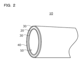
- FIG. 2 is a perspective view of an end portion of the vehicle component of this embodiment.
- FIG. 3 is a front view of a torsional fatigue test piece.
- FIG. 4 is a longitudinal side view of the torsional fatigue test piece.
- the inventors have studied vehicle parts with excellent fatigue strength, and steel pipes from which vehicle parts with excellent fatigue strength can be manufactured. As a result, the following findings were obtained.
- hollow vehicle parts are manufactured by cold bending a steel pipe and then quenching and tempering it.
- Patent Document 1 "In particular, surface decarburization is considered to be an important factor among surface properties. If surface decarburization occurs during the heating stage of quenching, it is possible to improve the surface hardness even if quenching is performed. As a result, sufficient fatigue properties cannot be obtained” (paragraph [0005] of Patent Document 1).
- Patent Literature 2 states, “Fatigue fracture may occur from the inner surface of the hollow stabilizer, which does not exist in the solid stabilizer. This is because even if the fatigue strength of the outer surface is improved by increasing the strength of the steel pipe, This is because the decarburized layer becomes the starting point of fatigue fracture" (paragraph [0005] of Patent Document 2). It is known that the formation of a decarburized layer in this way lowers the fatigue strength of a vehicle component including a hollow stabilizer.
- Patent Document 1 "The surface decarburization reaction when steel is heated progresses by outward diffusion of carbon atoms in the steel toward the surface and reaction with oxygen. This outward diffusion of carbon It is effective to increase the lattice constant of iron to suppress the "(paragraph [0017] of Patent Document 1). Therefore, in Patent Document 1, 0.010% or more of Sn, which is effective for increasing the lattice constant of iron, is contained to suppress the formation of a decarburized layer.
- Patent Document 2 states that "a decarburized layer is likely to be formed on the inner surface of the hollow stabilizer steel pipe when it is cooled from a high temperature at which the metal structure becomes an austenitic single phase and passes through a two-phase temperature range.” (Paragraph [0053] of Patent Document 2). Patent Document 2 describes that the formation of a decarburized layer can be suppressed by increasing the cooling rate when passing through the two-phase temperature (paragraph [0054] of Patent Document 2).
- the inventors have studied means for suppressing the formation of decarburized layers other than the means disclosed in Patent Documents 1 and 2.
- the decarburized layer is formed by quenching during manufacturing of vehicle parts. During heating and/or cooling for quenching, carbon in the steel out-diffuses to the surface and reacts with oxygen. This forms a decarburized layer.
- the present inventors paid attention to the behavior of oxygen during quenching. The present inventors thought that the formation of a decarburized layer could be suppressed by suppressing contact between the surface of a steel pipe for manufacturing vehicle parts and oxygen during quenching.
- the present inventors paid attention to the oxide film before quenching.
- An oxide film that suppresses contact between the steel pipe surface and oxygen is formed before quenching. It is believed that this suppresses contact between the surface of the steel pipe and oxygen during quenching, thereby suppressing the formation of a decarburized layer.
- the X-ray diffraction peak intensity ratio is 70% or more.
- Fe 3 O 4 , 20% or more Fe 2 O 3 , 10% or less FeO, and the balance consisting of impurities, the thickness is 0.80 to 2.50 ⁇ m, and the standard deviation of the thickness is 0.90 ⁇ m or less It has been found that the formation of an oxide film extends the rupture life of steel pipes after quenching.
- Heating during quenching thermally expands steel pipes for manufacturing vehicle parts. If the difference between the coefficient of linear expansion of the steel pipe and the coefficient of linear expansion of the oxide film on the surface of the steel pipe is small, the difference between the amount of change in the surface area of the steel pipe due to heating during quenching and the amount of change in volume of the oxide film is small. In this case, the oxide film is less likely to separate from the steel pipe surface, and the oxide film tends to remain on the steel pipe surface until just before quenching. In this case, contact between the steel pipe surface and oxygen is suppressed. It is conceivable that the coefficient of linear expansion of the oxide film having the composition described above is close to the coefficient of linear expansion of the steel pipe.
- the oxide film remains on the steel pipe surface until just before quenching, contact between the steel pipe surface and oxygen is suppressed. Therefore, formation of a decarburized layer is suppressed. As a result, the fatigue strength of the steel pipe is increased and the rupture life is extended.
- the oxide film in order to obtain the effect of suppressing contact between the steel pipe surface and oxygen, the oxide film must have a certain thickness or more. On the other hand, if the oxide film is too thick, the oxide film tends to peel off. Therefore, it is necessary to control the thickness of the oxide film within a certain range.
- the inventors have found the following matter.
- a vehicle part is manufactured by quenching the steel pipe provided with the oxide film described above, when the sum of the X-ray diffraction peak intensities of Fe 3 O 4 , FeO, and Fe 2 O 3 is taken as 100%, the X-ray Formation of an oxide film having a diffraction peak intensity ratio of 80% or more , FeO of 15% or less, Fe 2 O 3 of 5 % or less, and the balance being impurities, and having a thickness of 3.50 ⁇ m or less. It turns out that it will be.
- This vehicle component has a long rupture life and excellent fatigue strength.
- the steel pipe, steel pipe manufacturing method, vehicle component, and vehicle component manufacturing method of the present embodiment completed based on the above findings have the following configurations.
- Al 0 to 0.080%, Cr: 0 to 1.50%, Mo: 0 to 1.00%, Ni: 0 to 1.00%, Cu: 0 to 1.00%, Ti: 0 to 0.100%, Nb: 0 to 0.100%, V: 0 to 0.100%, B: 0 to 0.0050%, Ca: 0 to 0.0050%, and a chemical composition with the balance being Fe and impurities; and a microstructure composed of tempered martensite, A hollow base material having a Vickers hardness of 400 to 550 HV in accordance with JIS Z 2244:2020; on the base material, When the sum of the X-ray diffraction peak intensities of Fe 3 O 4 , FeO, and Fe 2 O 3 is taken as 100%, the peak intensity ratio of the X-ray diffraction is 80% or more , and 15% FeO below, Fe 2 O 3 below 5%, and the balance consisting of impurities, an oxide film having a thickness of 3.50 ⁇ m or less, vehicle parts.
- the vehicle component according to [3], The chemical composition, in mass %, Sol. Al: 0.001 to 0.080%, Cr: 0.01 to 1.50%, Mo: 0.01 to 1.00%, Ni: 0.01 to 1.00%, Cu: 0.01 to 1.00%, Ti: 0.001 to 0.100%, Nb: 0.001 to 0.100%, V: 0.001 to 0.100%, B: 0.0001 to 0.0050%, and Ca: 0.0001 to 0.0050%, containing one or more elements selected from the group consisting of vehicle parts.
- a method for manufacturing a vehicle part comprising: A step of preparing the steel pipe according to [1] or [2]; a step of bending the steel pipe; a step of holding the bent steel pipe at a temperature of Ac 3 +50° C. or higher and 1150° C. or lower for 10 seconds or longer and then quenching; a step of holding and tempering the steel pipe after the quenching at 150 to 350° C. for 10 minutes or longer; A method for manufacturing vehicle parts.
- FIG. 1 is a perspective view of the end of the steel pipe of this embodiment.
- steel pipe 1 includes base material 2 and oxide film 3 on base material 2 .
- Steel pipe 1 includes an outer surface 4 and an inner surface 5 .
- the oxide film 3 may be formed only on the outer surface 4 of the steel pipe 1, may be formed only on the inner surface 5, or may be formed on both the outer surface 4 and the inner surface 5. good.
- the decarburized layer on the outer surface of the vehicle component can be removed by shot peening, for example. On the other hand, the decarburized layer on the inner surface of the vehicle component may be difficult to remove.
- Steel pipe 1 is therefore preferably provided with an oxide layer 3 on at least the inner surface 5 .
- the steel pipe 1 may be a seamless steel pipe or an electric resistance welded steel pipe.
- the steel pipe 1 is an electric resistance welded steel pipe.
- the outer diameter of the steel pipe 1 is not particularly limited, it is, for example, 10 to 100 mm.
- the thickness of the steel pipe 1 is not particularly limited, it is, for example, 2 to 10 mm.
- the steel pipe 1 of this embodiment has the following features.
- the chemical composition of the base material 2 is, in mass %, C: 0.23 to 0.50%, Si: 0.01 to 0.50%, Mn: 0.50 to 2.50%, P: 0.050. % or less, S: 0.0100% or less, N: 0.0100% or less, O: 0.0100% or less, Sol.
- the microstructure of the base material 2 consists of 20% to 60% ferrite and 40% to 80% pearlite in area ratio.
- Fe 3 O 4 having an X-ray diffraction peak intensity ratio of 70% or more on the base material 2 when the sum of the X-ray diffraction peak intensities of Fe 3 O 4 , Fe 2 O 3 and FeO is 100%.
- the oxide film 3 has a thickness of 0.80 to 2.50 ⁇ m.
- the standard deviation of the thickness of oxide film 3 is 0.90 ⁇ m or less.
- C 0.23-0.50% Carbon (C) enhances the hardenability of steel. C further dissolves in steel. Thereby, C increases the strength of steel. If the C content is less than 0.23%, the above effect cannot be sufficiently obtained even if the content of other elements is within the range of the present embodiment. On the other hand, if the C content exceeds 0.50%, the hot workability of the steel deteriorates even if the content of other elements is within the range of the present embodiment. If the C content exceeds 0.50%, the toughness of the vehicle component after quenching is further reduced even if the content of other elements is within the range of the present embodiment. Therefore, the C content is 0.23-0.50%.
- the lower limit of the C content is preferably 0.25%, more preferably 0.27%, still more preferably 0.30%, still more preferably 0.33%, still more preferably 0.33%. It is 35%, more preferably 0.38%, and still more preferably 0.40%.
- the upper limit of the C content is preferably 0.48%, more preferably 0.46%, still more preferably 0.44%, still more preferably 0.42%, still more preferably 0.42%. 40%, more preferably 0.38%.
- Si 0.01-0.50% Silicon (Si) deoxidizes steel. Si also forms a solid solution in steel to increase the strength of the steel. If the Si content is less than 0.01%, the above effect cannot be sufficiently obtained even if the content of other elements is within the range of the present embodiment. On the other hand, if the Si content exceeds 0.50%, the ductility and toughness of the steel pipe 1 are lowered even if the content of other elements is within the range of the present embodiment. Therefore, the Si content is 0.01-0.50%.
- the lower limit of the Si content is preferably 0.05%, more preferably 0.10%, still more preferably 0.15%, still more preferably 0.20%, still more preferably 0 .25%.
- the upper limit of the Si content is preferably 0.45%, more preferably 0.40%, still more preferably 0.35%, still more preferably 0.30%.
- Mn 0.50-2.50%
- Manganese (Mn) increases the hardenability of steel. Mn further dissolves in steel. Thereby, Mn increases the strength of steel. If the Mn content is less than 0.50%, the above effect cannot be sufficiently obtained even if the content of other elements is within the range of the present embodiment. On the other hand, if the Mn content exceeds 2.50%, the toughness and ductility of the vehicle component after quenching decrease even if the contents of other elements are within the ranges of the present embodiment. Therefore, the Mn content is 0.50-2.50%.
- the lower limit of the Mn content is preferably 0.60%, more preferably 0.70%, still more preferably 0.75%, still more preferably 0.80%, still more preferably 0.80%.
- the upper limit of the Mn content is preferably 2.40%, more preferably 2.30%, still more preferably 2.20%, still more preferably 2.10%, still more preferably 2.10%. 00%, more preferably 1.90%, more preferably 1.80%, still more preferably 1.70%, still more preferably 1.60%, still more preferably 1.0%. 50%.
- P 0.050% or less Phosphorus (P) is an impurity. Therefore, the P content is over 0%. If the P content exceeds 0.050%, P segregates at the grain boundaries and reduces the ductility of the steel even if the content of other elements is within the range of the present embodiment. Therefore, the P content is 0.050% or less. The lower the P content, the better. However, drastic reduction of the P content greatly increases manufacturing costs. Therefore, when considering industrial production, the lower limit of the P content is preferably 0.001%, more preferably 0.002%, still more preferably 0.003%, still more preferably 0.005 %. The upper limit of the P content is preferably 0.040%, more preferably 0.030%, still more preferably 0.020%, still more preferably 0.010%.
- S 0.0100% or less Sulfur (S) is an impurity. Therefore, the S content is over 0%. If the S content exceeds 0.0100%, the hot workability, toughness and fatigue strength of the steel are lowered even if the contents of other elements are within the range of the present embodiment. Therefore, the S content is 0.0100% or less. The lower the S content, the better. However, drastic reduction of the S content greatly increases manufacturing costs. Therefore, when considering industrial production, the lower limit of the S content is preferably 0.0001%, more preferably 0.0002%, still more preferably 0.0003%, still more preferably 0.0005 %. The upper limit of the S content is preferably 0.0080%, more preferably 0.0070%, still more preferably 0.0060%, still more preferably 0.0050%, still more preferably 0.0050%. 0040%.
- N 0.0100% or less Nitrogen (N) is an impurity. Therefore, the N content is over 0%. If the N content exceeds 0.0100%, the toughness of the steel is lowered even if the content of other elements is within the range of the present embodiment. Therefore, the N content is 0.0100% or less.
- N forms nitrides and/or carbonitrides to increase the strength of steel.
- the preferred lower limit of the N content is 0.0001%, more preferably 0.0002%, still more preferably 0.0003%, still more preferably 0.0005%, still more preferably 0.0010 %, more preferably 0.0020%, more preferably 0.0030%.
- the upper limit of the N content is preferably 0.0080%, more preferably 0.0070%, still more preferably 0.0060%, still more preferably 0.0050%, still more preferably 0.0050%. 0040%.
- Oxygen (O) is an impurity. Therefore, the O content is over 0%. If the O content exceeds 0.0100%, the toughness of the steel is lowered even if the content of other elements is within the range of the present embodiment. Therefore, the O content is 0.0100% or less. The lower the O content, the better. However, drastic reduction of O content greatly increases manufacturing cost. Therefore, when considering industrial production, the preferred lower limit of the O content is 0.0001%, more preferably 0.0002%, still more preferably 0.0003%, still more preferably 0.0005% is. The upper limit of the O content is preferably 0.0080%, more preferably 0.0070%, still more preferably 0.0060%, still more preferably 0.0050%, still more preferably 0.0050%. 0040%, more preferably 0.0030%.
- the rest of the chemical composition of the steel pipe 1 of this embodiment consists of Fe and impurities.
- the impurities in the chemical composition are those that are mixed from ore, scrap, or the manufacturing environment as raw materials when the steel pipe 1 is industrially manufactured, and are not intentionally included. , means a permissible range that does not adversely affect the steel pipe 1 of the present embodiment.
- the chemical composition of the base material 2 of the steel pipe 1 according to this embodiment may further contain Al instead of part of Fe.
- Al is an optional element and may not be contained. That is, the Al content may be 0%.
- Al deoxidizes the steel.
- Al further combines with nitrogen (N) to produce AlN.
- AlN suppresses coarsening of crystal grains during quenching. If even a small amount of Al is contained, the above effect can be obtained to some extent.
- Al content exceeds 0.080%, even if the content of other elements is within the range of the present embodiment, Al combines with oxygen (O) to excessively generate inclusions. This reduces the fatigue strength of the vehicle component. Therefore, the Al content is 0-0.080%.
- the lower limit of the Al content is preferably more than 0%, more preferably 0.001%, still more preferably 0.005%, still more preferably 0.010%, still more preferably 0.015 %.
- the upper limit of the Al content is preferably 0.070%, more preferably 0.060%, still more preferably 0.050%, still more preferably 0.040%, still more preferably 0.040%. 030%.
- the chemical composition of the base material 2 of the steel pipe 1 according to this embodiment may further contain one or more elements selected from the group consisting of Cr, Mo, Ni and Cu instead of part of Fe. All of these elements are optional elements and may not be contained. Both of these elements, when included, increase the strength of the steel.
- Chromium (Cr) is an optional element and may not be contained. That is, the Cr content may be 0%. When Cr is included, that is, when the Cr content is greater than 0%, Cr increases the strength of the steel. If even a little Cr is contained, the above effect can be obtained to some extent. On the other hand, if the Cr content exceeds 1.50%, the ductility of the steel is lowered even if the contents of other elements are within the range of the present embodiment. Therefore, the Cr content is 0-1.50%.
- the lower limit of the Cr content is preferably 0.01%, more preferably 0.05%, still more preferably 0.10%, still more preferably 0.20%, still more preferably 0.20%. 30%.
- the upper limit of the Cr content is preferably 1.20%, more preferably 1.00%, still more preferably 0.80%, still more preferably 0.60%, still more preferably 0.60%. 40%.
- Mo Molybdenum
- Mo is an optional element and may not be contained. That is, the Mo content may be 0%. When Mo is contained, that is, when the Mo content is over 0%, Mo enhances the strength of the steel. If even a little Mo is contained, the above effect can be obtained to some extent. On the other hand, if the Mo content exceeds 1.00%, the ductility of the steel is lowered even if the contents of other elements are within the range of the present embodiment. Therefore, the Mo content is 0-1.00%.
- the lower limit of the Mo content is preferably 0.01%, more preferably 0.02%, still more preferably 0.03%, still more preferably 0.04%, still more preferably 0.04%. 05%.
- the upper limit of the Mo content is preferably 0.80%, more preferably 0.60%, still more preferably 0.40%, still more preferably 0.20%, still more preferably 0.20%. 10%.
- Nickel (Ni) is an optional element and may not be contained. That is, the Ni content may be 0%. When Ni is contained, that is, when the Ni content is over 0%, Ni increases the strength of the steel. If Ni is contained even in a small amount, the above effect can be obtained to some extent. On the other hand, if the Ni content exceeds 1.00%, the ductility of the steel is lowered even if the content of other elements is within the range of the present embodiment. Therefore, the Ni content is 0-1.00%.
- the lower limit of the Ni content is preferably 0.01%, more preferably 0.02%, still more preferably 0.05%, still more preferably 0.10%, still more preferably 0.05%. 15%.
- the upper limit of the Ni content is preferably 0.80%, more preferably 0.60%, still more preferably 0.40%, still more preferably 0.20%.
- Cu Copper (Cu) is an optional element and may not be contained. That is, the Cu content may be 0%. When Cu is contained, that is, when the Cu content is greater than 0%, Cu increases the strength of the steel. If even a small amount of Cu is contained, the above effects can be obtained to some extent. On the other hand, if the Cu content exceeds 1.00%, the ductility of the steel is lowered even if the content of other elements is within the range of the present embodiment. Therefore, the Cu content is 0-1.00%.
- the lower limit of the Cu content is preferably 0.01%, more preferably 0.02%, still more preferably 0.03%, still more preferably 0.04%, still more preferably 0.04%. 05%.
- the upper limit of the Cu content is preferably 0.80%, more preferably 0.60%, still more preferably 0.40%, still more preferably 0.20%.
- the chemical composition of the base material 2 of the steel pipe 1 according to the present embodiment may further contain one or more elements selected from the group consisting of Ti, Nb and V instead of part of Fe. All of these elements are optional elements and may not be contained. Both of these elements, when included, increase the strength and workability of the steel.
- Titanium (Ti) is an optional element and may not be contained. That is, the Ti content may be 0%. When Ti is contained, ie when the Ti content is greater than 0%, Ti forms carbides, nitrides and/or carbonitrides. This increases the strength and workability of the steel. If even a small amount of Ti is contained, the above effect can be obtained to some extent. On the other hand, if the Ti content exceeds 0.100%, the ductility of the steel is lowered even if the contents of other elements are within the range of the present embodiment. Therefore, the Ti content is 0-0.100%.
- the lower limit of the Ti content is preferably 0.001%, more preferably 0.005%, still more preferably 0.010%, still more preferably 0.020%, still more preferably 0.020%. 030%.
- the upper limit of the Ti content is preferably 0.090%, more preferably 0.080%, still more preferably 0.070%, still more preferably 0.060%.
- Niobium (Nb) is an optional element and may not be contained. That is, the Nb content may be 0%. If Nb is included, ie if the Nb content is greater than 0%, Nb forms carbides, nitrides and/or carbonitrides. This increases the strength and workability of the steel. If even a small amount of Nb is contained, the above effect can be obtained to some extent. On the other hand, if the Nb content exceeds 0.100%, the ductility of the steel is lowered even if the content of other elements is within the range of the present embodiment. Therefore, the Nb content is 0-0.100%.
- the lower limit of the Nb content is preferably 0.001%, more preferably 0.002%, still more preferably 0.005%, still more preferably 0.010%, still more preferably 0.01%. 015%.
- the upper limit of the Nb content is preferably 0.090%, more preferably 0.070%, still more preferably 0.050%, still more preferably 0.030%, still more preferably 0.030%. 020%.
- V 0-0.100%
- Vanadium (V) is an optional element and may not be contained. That is, the V content may be 0%.
- V When V is included, ie when the V content is greater than 0%, V forms carbides, nitrides and/or carbonitrides. This increases the strength and workability of the steel. If even a small amount of V is contained, the above effect can be obtained to some extent. On the other hand, if the V content exceeds 0.100%, the ductility of the steel is lowered even if the content of other elements is within the range of the present embodiment. Therefore, the V content is 0-0.100%.
- the lower limit of the V content is preferably 0.001%, more preferably 0.005%, still more preferably 0.010%, still more preferably 0.015%, still more preferably 0.01%. 020%.
- the upper limit of the V content is preferably 0.090%, more preferably 0.080%, still more preferably 0.070%, still more preferably 0.060%, still more preferably 0.060%. 050%, more preferably 0.040%.
- the chemical composition of the base material 2 of the steel pipe 1 according to this embodiment may further contain B instead of part of Fe.
- B 0 to 0.0050% Boron (B) is an optional element and may not be contained. That is, the B content may be 0%. When B is contained, that is, when the B content is over 0%, B enhances the hardenability of the steel. If even a small amount of B is contained, the above effect can be obtained to some extent. On the other hand, if the B content exceeds 0.0050%, the steel tends to embrittle even if the content of other elements is within the range of the present embodiment. Therefore, the B content is 0-0.0050%.
- the lower limit of the B content is preferably 0.0001%, more preferably 0.0002%, still more preferably 0.0003%, still more preferably 0.0005%, still more preferably 0.0005%. 0010%.
- the upper limit of the B content is preferably 0.0040%, more preferably 0.0030%, still more preferably 0.0020%.
- the chemical composition of the base material 2 of the steel pipe 1 according to this embodiment may further contain Ca instead of part of Fe.
- Ca 0-0.0050% Calcium (Ca) is an optional element and may not be contained. That is, the Ca content may be 0%. When Ca is contained, that is, when the Ca content is over 0%, Ca enhances the hot workability of the steel. If even a little Ca is contained, the above effect can be obtained to some extent. On the other hand, if the Ca content exceeds 0.0050%, the toughness of the steel is lowered even if the content of other elements is within the range of the present embodiment. Therefore, the Ca content is 0-0.0050%.
- the lower limit of the Ca content is preferably 0.0001%, more preferably 0.0002%, still more preferably 0.0003%, still more preferably 0.0005%, still more preferably 0.0005%. 0010%, more preferably 0.0015%.
- the upper limit of the Ca content is preferably 0.0040%, more preferably 0.0030%, still more preferably 0.0025%.
- the chemical composition of the base material 2 of the steel pipe 1 of this embodiment can be measured by a known component analysis method.
- a steel pipe 1 is cut into lengths of 10 cm in the axial direction of the steel pipe 1 .
- the oxide film 3 on the outer surface 4 and the inner surface 5 of the cut steel pipe 1 is removed by cutting.
- the steel pipe 1 from which the oxide film 3 has been removed is finely pulverized and dissolved in acid to obtain a solution.
- ICP-AES Inductively Coupled Plasma Atomic Emission Spectrometry
- the C content and S content are obtained by a well-known high-frequency combustion method (combustion-infrared absorption method).
- the N content is determined using the well-known inert gas fusion-thermal conductivity method.
- the O content is determined using a well-known inert gas fusion-nondispersive infrared absorption method.
- each element content based on the significant digits defined in this embodiment, rounded off the measured numerical value, the numerical value up to the minimum digit of each element content defined in this embodiment do.
- the C content of the steel pipe 1 of the present embodiment is specified by a numerical value up to the second decimal place. Therefore, the C content is a numerical value to the second decimal place obtained by rounding the measured numerical value to the third decimal place.
- the contents of elements other than the C content of the steel pipe 1 of the present embodiment are obtained by rounding the measured values to the minimum digit specified in the present embodiment.
- the value is taken as the elemental content. Rounding means rounding down if the fraction is less than 5, and rounding up if the fraction is 5 or more.
- the base material 2 of the steel pipe 1 of this embodiment has a microstructure composed of 20% to 60% ferrite and 40% to 80% pearlite in area ratio.
- a vehicle component can be manufactured by quenching and tempering the steel pipe 1 after cold bending. Therefore, the steel pipe 1 is required to have excellent workability.
- the microstructure of the base material 2 consists of 20% to 60% ferrite and 40% to 80% pearlite in area ratio, the steel pipe 1 has excellent workability.
- the lower limit of the area ratio of ferrite is preferably 25%, more preferably 30%, still more preferably 35%, still more preferably 40%.
- the upper limit of the ferrite area ratio is preferably 55%, more preferably 50%, and still more preferably 45%.
- the lower limit of the area ratio of pearlite is preferably 45%, more preferably 50%, and still more preferably 55%.
- the upper limit of the area ratio of pearlite is preferably 75%, more preferably 70%, still more preferably 65%, still more preferably 60%.
- the area ratios of ferrite and pearlite in the base material 2 of the steel pipe 1 are obtained by the following method.
- a test piece having a length of 10 cm in the axial direction of the steel pipe 1 including the thickness central portion of the cross section perpendicular to the axial direction of the steel pipe 1 is taken at any three locations of the steel pipe 1 . That is, three specimens are taken.
- the surface corresponding to the cross section perpendicular to the axial direction of the steel pipe 1 is used as the observation surface.
- the viewing surface of each specimen is mirror-polished. Etching is performed on the mirror-polished observation surface using 3% nitric acid alcohol (nital etchant).
- Let the thickness center part of the steel pipe 1 be an observation field among the etched observation surfaces.
- the size of the observation field is 200 ⁇ m ⁇ 200 ⁇ m.
- the field of view is observed with a 500x optical microscope.
- each structure such as pearlite and ferrite can be easily distinguished by contrast.
- ferrite is observed as white areas.
- Pearlite is observed as a region with a lamellar texture that is less bright than ferrite. Identify each tissue in the field of view. Then, the area ratio (%) of ferrite is obtained based on the area of ferrite in the observation field of view and the total area of the observation field of view. Based on the pearlite area in the observation field of view and the total area of the observation field of view, the pearlite area ratio (%) is determined. The arithmetic mean value of the values obtained from the three test pieces is used as the area ratio of ferrite and the area ratio of pearlite.
- a steel pipe 1 of this embodiment has an oxide film 3 on a base material 2 .
- the oxide film 3 has an X-ray diffraction peak intensity ratio of 70% or more when the sum of the X-ray diffraction peak intensities of Fe 3 O 4 , Fe 2 O 3 and FeO is 100%. 20% or more of Fe 2 O 3 , 10% or less of FeO, and the balance consists of impurities.
- An oxide film 3 having the composition described above is formed on a steel pipe 1 before quenching. This increases the fatigue strength of the vehicle component.
- the lower limit of the peak intensity ratio of Fe 3 O 4 is preferably 72%, more preferably 74%, still more preferably 75%.
- the upper limit of the peak intensity ratio of Fe 3 O 4 is not particularly limited, it is, for example, 80%.
- the upper limit of the peak intensity ratio of Fe 3 O 4 is preferably 78%, more preferably 76%, still more preferably 75%.
- the lower limit of the peak intensity ratio of Fe 2 O 3 is preferably 21%, more preferably 22%, still more preferably 23%, still more preferably 25%.
- the upper limit of the peak intensity ratio of Fe 2 O 3 is not particularly limited, it is, for example, 30%.
- the upper limit of the peak intensity ratio of Fe 2 O 3 is preferably 29%, more preferably 28%, still more preferably 27%.
- the lower limit of the FeO peak intensity ratio is not particularly limited, and may be 0%.
- the upper limit of the peak intensity ratio of FeO is preferably 8%, more preferably 6%, still more preferably 4%, still more preferably 2%.
- composition of the oxide film 3 of the steel pipe 1 is obtained by the following method.
- X-ray diffraction measurement is performed on the surface of oxide film 3 to obtain an X-ray diffraction profile. Measurement is performed at three arbitrary points on the surface of oxide film 3 .
- the measurement conditions for the X-ray diffraction measurement are as follows.
- X-ray tube Cu-K ⁇ ray (assumed to be Cu-K ⁇ 1 ray by using a monochromator)
- Scan method Continuous scan Continuous scan speed: 2.0°/min
- the X-ray diffraction peak intensities of Fe 3 O 4 , Fe 2 O 3 and FeO are determined.
- the sum of the X-ray diffraction peak intensities of Fe 3 O 4 , Fe 2 O 3 and FeO is taken as 100%.
- the peak intensity ratio of Fe 3 O 4 , Fe 2 O 3 and FeO is determined from the sum of the peak intensities and the X-ray diffraction peak intensities of Fe 3 O 4 , Fe 2 O 3 and FeO.
- oxide film 3 has a thickness of 0.80 to 2.50 ⁇ m.
- the lower limit of the thickness of oxide film 3 is preferably 0.84 ⁇ m, more preferably 0.88 ⁇ m, still more preferably 1.00 ⁇ m, still more preferably 1.20 ⁇ m.
- the upper limit of the thickness of the oxide film 3 is preferably 2.40 ⁇ m, more preferably 2.30 ⁇ m, still more preferably 2.20 ⁇ m, still more preferably 2.00 ⁇ m, still more preferably 1.80 ⁇ m. is.
- the thickness of the oxide film 3 of the steel pipe 1 is obtained by the following method.
- a test piece is taken by cutting the steel pipe 1 perpendicularly to the axial direction.
- Three test pieces are taken in the axial direction of the steel pipe 1 at a pitch of 100 mm.
- the cut surface perpendicular to the axial direction of the steel pipe 1 is the observation surface. Fill with resin so that the observation surface can be observed. After filling with resin, the observation surface is polished.
- a scanning electron microscope (SEM)-energy dispersive X-ray spectrometer (EDS) is used on the observation surface after polishing to generate a secondary electron image of the observation field including the oxide film 3 of the observation surface. do.
- the size of the observation field is 50 ⁇ m ⁇ 40 ⁇ m.
- the observation field of view is 50 ⁇ m in the radial direction of the steel pipe 1 and 40 ⁇ m in the direction perpendicular to the radial direction (corresponding to the circumferential direction, hereinafter referred to as the C direction) on the observation surface.
- the base material 2 and the oxide film 3 can be easily distinguished by contrast.
- the base material 2 and the oxide film 3 may be distinguished from each other by performing elemental mapping of oxygen (O) in the observation field using an EDS device attached to the SEM.
- elemental mapping of oxygen (O) by EDS a region with a high oxygen concentration corresponds to the oxide film 3 and a region with a low oxygen concentration corresponds to the base material 2 . Since a region with a high oxygen concentration and a region with a low oxygen concentration are clearly separated, the oxide film 3 can be easily distinguished.
- the thickness of the identified oxide film 3 is measured at 10 locations in the C direction at a pitch of 3 ⁇ m.
- the arithmetic mean value of the thickness of the oxide film 3 at the measurement points (30 points in total) of the three test pieces is taken as the thickness of the oxide film 3 .
- the standard deviation of the thickness of the oxide film 3 exceeds 0.90 ⁇ m, the contact between the surfaces 4 and 5 of the steel pipe 1 and oxygen cannot be suppressed in the portion where the oxide film 3 is thin. In this case, intergranular oxidation occurs locally on the surfaces 4 and 5 of the steel pipe 1 . In the part where the grain boundary oxidation occurs, a dent occurs locally. The fatigue strength of the vehicle component decreases due to the concentration of stress on the recess. Therefore, the standard deviation of the thickness of oxide film 3 is 0.90 ⁇ m or less. The lower limit of the standard deviation of the thickness of oxide film 3 may be 0 ⁇ m.
- the lower limit of the standard deviation of the thickness of the oxide film 3 is preferably 0.01 ⁇ m, more preferably 0.03 ⁇ m, More preferably, it is 0.05 ⁇ m.
- the upper limit of the thickness of the oxide film 3 is preferably 0.80 ⁇ m, more preferably 0.70 ⁇ m, still more preferably 0.60 ⁇ m, still more preferably 0.50 ⁇ m.
- the method for measuring the standard deviation of the oxide film thickness of steel pipes is obtained by the following method.
- the thickness of the oxide film 3 is measured by the above-described [Method for measuring thickness of oxide film of steel pipe].
- standard deviation is sample standard deviation (JIS Z8101-1:2015).
- An example of the method for manufacturing the steel pipe 1 of this embodiment includes the following steps.
- (Step 1) Steel plate preparation step (Step 2) Low temperature heat treatment step (Step 3) Pipe making step
- Step 2) Steel plate preparation step (Step 2) Low temperature heat treatment step (Step 3) Pipe making step
- Step 1 Steel plate preparation step
- a steel plate for manufacturing the steel pipe 1 of the present embodiment is prepared.
- the steel plate may be obtained from a third party or manufactured.
- molten steel is produced in which the content of each element in the chemical composition is within the range of the present embodiment.
- a refining method is not particularly limited, and a well-known method may be used.
- molten steel a material is manufactured by a well-known casting method. For example, an ingot may be manufactured by an ingot casting method using molten steel. Moreover, you may manufacture a bloom by the continuous casting method using molten steel. A raw material (ingot or bloom) is manufactured by the above method.
- the raw material is heated and subjected to rough rolling and finish rolling by well-known methods.
- the coiling temperature of the steel sheet is, for example, over 600 to 700°C.
- Step 2 Low temperature heat treatment step
- the steel sheet is subjected to low-temperature heat treatment under the following conditions.
- (Manufacturing condition 1) Heat treatment temperature: 450-600°C (Manufacturing condition 2) Heat treatment time: 0.5 to 3.0 minutes
- the manufactured hot-rolled steel sheet is in a state of being wound into a coil.
- the steel sheet is unwound and subjected to low-temperature heat treatment while the surface of the steel sheet is exposed to the atmosphere.
- the low temperature heat treatment conditions are as described above.
- the surface of the steel sheet has an X-ray diffraction peak intensity ratio of 70% or more Fe 3 O 4 , 20% or more Fe 2 O 3 , 10% or less FeO, and the balance is impurities, and the thickness is An oxide film 3 having a thickness of 0.80 to 2.50 ⁇ m and a standard deviation of thickness of 0.90 ⁇ m or less is formed. Formation of the oxide film described above increases the fatigue strength of the vehicle component.
- the preferred lower limit of the heat treatment temperature is over 450°C, more preferably 460°C, and even more preferably 470°C.
- Step 3 Electric resistance welded steel pipes are manufactured using hot-rolled steel sheets subjected to low-temperature heat treatment.
- a forming roll is used to form a hot-rolled steel sheet into a cylindrical blank pipe (open pipe).
- the formed blank tube is formed so that the width direction of the hot-rolled steel sheet coincides with the circumferential direction of the blank tube.
- Electric resistance welding is performed on butt portions extending in the longitudinal direction of the tube.
- An electric resistance welded steel pipe is manufactured by the pipe manufacturing process described above.
- the steel pipe 1 of the present embodiment can be manufactured through the above steps.
- the method for manufacturing the steel pipe 1 of this embodiment may further include other steps.
- Another process is, for example, a diameter-reducing rolling process.
- diameter-reducing rolling step for example, diameter-reducing rolling may be performed under well-known conditions.
- the steel pipe 1 of the present disclosure is used as a material for vehicle parts.
- Vehicle parts are, for example, stabilizers, inner tie rods, drive shafts, upper arms, and the like.
- the steel pipe 1 is suitable for stabilizer applications.
- the steel pipe 1 of this embodiment has the following features.
- the chemical composition of the base material 2 is, in mass %, C: 0.23 to 0.50%, Si: 0.01 to 0.50%, Mn: 0.50 to 2.50%, P: 0.050. % or less, S: 0.0100% or less, N: 0.0100% or less, O: 0.0100% or less, Sol.
- the microstructure of the base material 2 consists of 20% to 60% ferrite and 40% to 80% pearlite in area ratio.
- Fe 3 O 4 having an X-ray diffraction peak intensity ratio of 70% or more on the base material 2 when the sum of the X-ray diffraction peak intensities of Fe 3 O 4 , Fe 2 O 3 and FeO is 100%.
- the steel pipe 1 of this embodiment having features 1 to 5 can be used to manufacture vehicle parts with excellent fatigue strength. That is, with the steel pipe 1 of the present embodiment, excellent fatigue strength can be obtained in a vehicle component manufactured using the steel pipe 1 as a raw material.
- FIG. 2 is a perspective view of an end portion of the vehicle component of this embodiment.
- vehicle component 10 includes hollow base material 20 and oxide film 30 on base material 20 .
- Vehicle component 10 includes an outer surface 40 and an inner surface 50 .
- the oxide film 30 may be formed only on the outer surface 40 of the vehicle component 10, may be formed only on the inner surface 50, or may be formed on both the outer surface 40 and the inner surface 50.
- the decarburized layer on the outer surface 40 of the vehicle component 10 can be removed by shot peening, for example. On the other hand, the decarburized layer on the inner surface 50 of the vehicle component 10 may be difficult to remove. Therefore, vehicle component 10 preferably comprises oxide layer 30 at least on inner surface 50 .
- the vehicle parts 10 are, for example, stabilizers, inner tie rods, drive shafts, upper arms, and the like.
- the vehicle component 10 of this embodiment has the following features.
- the chemical composition of the base material 20 is, in mass %, C: 0.23 to 0.50%, Si: 0.01 to 0.50%, Mn: 0.50 to 2.50%, P: 0.050. % or less, S: 0.0100% or less, N: 0.0100% or less, O: 0.0100% or less, Sol.
- the microstructure of the base material 20 consists of tempered martensite and has a Vickers hardness of 400 to 550 HV according to JIS Z 2244:2020.
- Fe 3 O 4 having an X-ray diffraction peak intensity ratio of 80% or more when the sum of the X-ray diffraction peak intensities of Fe 3 O 4 , FeO, and Fe 2 O 3 on the base material 20 is 100%. , 15% or less of FeO, 5% or less of Fe 2 O 3 , and the balance being impurities.
- the thickness of oxide film 30 is 3.50 ⁇ m or less. Characteristics 6 to 9 will be described below.
- C 0.23-0.50% Carbon (C) enhances the hardenability of steel. C further dissolves in steel. Thereby, C increases the strength of steel. If the C content is less than 0.23%, the above effect cannot be sufficiently obtained even if the content of other elements is within the range of the present embodiment. On the other hand, if the C content exceeds 0.50%, the hot workability of the steel deteriorates even if the content of other elements is within the range of the present embodiment. If the C content exceeds 0.50%, the toughness of the vehicle component 10 after quenching is further reduced even if the content of other elements is within the range of the present embodiment. Therefore, the C content is 0.23-0.50%.
- the lower limit of the C content is preferably 0.25%, more preferably 0.27%, still more preferably 0.30%, still more preferably 0.33%, still more preferably 0.33%. It is 35%, more preferably 0.38%, and still more preferably 0.40%.
- the upper limit of the C content is preferably 0.48%, more preferably 0.46%, still more preferably 0.44%, still more preferably 0.42%, still more preferably 0.42%. 40%, more preferably 0.38%.
- Si 0.01-0.50% Silicon (Si) deoxidizes steel. Si also forms a solid solution in steel to increase the strength of the steel. If the Si content is less than 0.01%, the above effect cannot be sufficiently obtained even if the content of other elements is within the range of the present embodiment. On the other hand, if the Si content exceeds 0.50%, the ductility and toughness of the vehicle component 10 are lowered even if the content of other elements is within the range of the present embodiment. Therefore, the Si content is 0.01-0.50%.
- the lower limit of the Si content is preferably 0.05%, more preferably 0.10%, still more preferably 0.15%, still more preferably 0.20%, still more preferably 0 .25%.
- the upper limit of the Si content is preferably 0.45%, more preferably 0.40%, still more preferably 0.35%, still more preferably 0.30%.
- Mn 0.50-2.50%
- Manganese (Mn) increases the hardenability of steel. Mn further dissolves in steel. Thereby, Mn increases the strength of steel. If the Mn content is less than 0.50%, the above effect cannot be sufficiently obtained even if the content of other elements is within the range of the present embodiment. On the other hand, if the Mn content exceeds 2.50%, the toughness and ductility of the vehicle component 10 after quenching decrease even if the contents of other elements are within the ranges of the present embodiment. Therefore, the Mn content is 0.50-2.50%.
- the lower limit of the Mn content is preferably 0.60%, more preferably 0.70%, still more preferably 0.75%, still more preferably 0.80%, still more preferably 0.80%.
- the upper limit of the Mn content is preferably 2.40%, more preferably 2.30%, still more preferably 2.20%, still more preferably 2.10%, still more preferably 2.10%. 00%, more preferably 1.90%, more preferably 1.80%, still more preferably 1.70%, still more preferably 1.60%, still more preferably 1.0%. 50%.
- P 0.050% or less Phosphorus (P) is an impurity. Therefore, the P content is over 0%. If the P content exceeds 0.050%, P segregates at the grain boundaries and reduces the ductility of the steel even if the content of other elements is within the range of the present embodiment. Therefore, the P content is 0.050% or less. The lower the P content, the better. However, drastic reduction of the P content greatly increases manufacturing costs. Therefore, when considering industrial production, the lower limit of the P content is preferably 0.001%, more preferably 0.002%, still more preferably 0.003%, still more preferably 0.005 %. The upper limit of the P content is preferably 0.040%, more preferably 0.030%, still more preferably 0.020%, still more preferably 0.010%.
- S 0.0100% or less Sulfur (S) is an impurity. Therefore, the S content is over 0%. If the S content exceeds 0.0100%, the hot workability, toughness and fatigue strength of the steel are lowered even if the contents of other elements are within the range of the present embodiment. Therefore, the S content is 0.0100% or less. The lower the S content, the better. However, drastic reduction of the S content greatly increases manufacturing costs. Therefore, when considering industrial production, the lower limit of the S content is preferably 0.0001%, more preferably 0.0002%, still more preferably 0.0003%, still more preferably 0.0005 %. The upper limit of the S content is preferably 0.0080%, more preferably 0.0070%, still more preferably 0.0060%, still more preferably 0.0050%, still more preferably 0.0050%. 0040%.
- N 0.0100% or less Nitrogen (N) is an impurity. Therefore, the N content is over 0%. If the N content exceeds 0.0100%, the toughness of the steel is lowered even if the content of other elements is within the range of the present embodiment. Therefore, the N content is 0.0100% or less.
- N forms nitrides and/or carbonitrides to increase the strength of steel.
- the preferred lower limit of the N content is 0.0001%, more preferably 0.0002%, still more preferably 0.0003%, still more preferably 0.0005%, still more preferably 0.0010 %, more preferably 0.0020%, more preferably 0.0030%.
- the upper limit of the N content is preferably 0.0080%, more preferably 0.0070%, still more preferably 0.0060%, still more preferably 0.0050%, still more preferably 0.0050%. 0040%.
- Oxygen (O) is an impurity. Therefore, the O content is over 0%. If the O content exceeds 0.0100%, the toughness of the steel is lowered even if the content of other elements is within the range of the present embodiment. Therefore, the O content is 0.0100% or less. The lower the O content, the better. However, drastic reduction of O content greatly increases manufacturing cost. Therefore, when considering industrial production, the preferred lower limit of the O content is 0.0001%, more preferably 0.0002%, still more preferably 0.0003%, still more preferably 0.0005% is. The upper limit of the O content is preferably 0.0080%, more preferably 0.0070%, still more preferably 0.0060%, still more preferably 0.0050%, still more preferably 0.0050%. 0040%, more preferably 0.0030%.
- the rest of the chemical composition of the base material 20 of the vehicle component 10 of the present embodiment consists of Fe and impurities.
- the impurities in the chemical composition are those that are mixed from ore, scrap, or the manufacturing environment as raw materials when the base material 20 of the vehicle component 10 is industrially manufactured. It does not mean that it is contained, but that it is permissible within a range that does not adversely affect the base material 20 of the vehicle component 10 of the present embodiment.
- the chemical composition of the base material 20 of the vehicle component 10 according to the present embodiment may further contain Al instead of part of Fe.
- Al is an optional element and may not be contained. That is, the Al content may be 0%.
- Al deoxidizes the steel.
- Al further combines with nitrogen (N) to produce AlN.
- AlN suppresses coarsening of crystal grains during quenching. If even a small amount of Al is contained, the above effect can be obtained to some extent.
- Al content exceeds 0.080%, even if the content of other elements is within the range of the present embodiment, Al combines with oxygen (O) to excessively generate inclusions. This reduces the fatigue strength of the vehicle component 10 . Therefore, the Al content is 0-0.080%.
- the lower limit of the Al content is preferably more than 0%, more preferably 0.001%, still more preferably 0.005%, still more preferably 0.010%, still more preferably 0.015 %.
- the upper limit of the Al content is preferably 0.070%, more preferably 0.060%, still more preferably 0.050%, still more preferably 0.040%, still more preferably 0.040%. 030%.
- the chemical composition of the base material 20 of the vehicle component 10 according to this embodiment may further contain one or more elements selected from the group consisting of Cr, Mo, Ni and Cu instead of part of Fe. All of these elements are optional elements and may not be contained. When included, both of these elements increase the strength of vehicle component 10 .
- Chromium (Cr) is an optional element and may not be contained. That is, the Cr content may be 0%. When Cr is contained, that is, when the Cr content is over 0%, Cr enhances the strength of the vehicle component 10 . If even a little Cr is contained, the above effect can be obtained to some extent. On the other hand, if the Cr content exceeds 1.50%, the ductility of the vehicle component 10 is lowered even if the content of other elements is within the range of the present embodiment. Therefore, the Cr content is 0-1.50%.
- the lower limit of the Cr content is preferably 0.01%, more preferably 0.05%, still more preferably 0.10%, still more preferably 0.20%, still more preferably 0.20%. 30%.
- the upper limit of the Cr content is preferably 1.20%, more preferably 1.00%, still more preferably 0.80%, still more preferably 0.60%, still more preferably 0.60%. 40%.
- Mo Molybdenum
- Mo is an optional element and may not be contained. That is, the Mo content may be 0%. When Mo is contained, that is, when the Mo content is over 0%, Mo enhances the strength of the vehicle component 10 . If even a little Mo is contained, the above effect can be obtained to some extent. On the other hand, if the Mo content exceeds 1.00%, the ductility of the vehicle component 10 is lowered even if the content of other elements is within the range of the present embodiment. Therefore, the Mo content is 0-1.00%.
- the lower limit of the Mo content is preferably 0.01%, more preferably 0.02%, still more preferably 0.03%, still more preferably 0.04%, still more preferably 0.04%. 05%.
- the upper limit of the Mo content is preferably 0.80%, more preferably 0.60%, still more preferably 0.40%, still more preferably 0.20%, still more preferably 0.20%. 10%.
- Nickel (Ni) is an optional element and may not be contained. That is, the Ni content may be 0%. When Ni is contained, that is, when the Ni content is over 0%, Ni enhances the strength of the vehicle component 10 . If Ni is contained even in a small amount, the above effect can be obtained to some extent. On the other hand, if the Ni content exceeds 1.00%, the ductility of the vehicle component 10 is lowered even if the content of other elements is within the range of the present embodiment. Therefore, the Ni content is 0-1.00%.
- the lower limit of the Ni content is preferably 0.01%, more preferably 0.02%, still more preferably 0.05%, still more preferably 0.10%, still more preferably 0.05%. 15%.
- the upper limit of the Ni content is preferably 0.80%, more preferably 0.60%, still more preferably 0.40%, still more preferably 0.20%.
- Cu Copper (Cu) is an optional element and may not be contained. That is, the Cu content may be 0%. When Cu is contained, that is, when the Cu content is over 0%, Cu enhances the strength of the vehicle component 10 . If even a small amount of Cu is contained, the above effects can be obtained to some extent. On the other hand, if the Cu content exceeds 1.00%, the ductility of the vehicle component 10 is lowered even if the content of other elements is within the range of the present embodiment. Therefore, the Cu content is 0-1.00%.
- the lower limit of the Cu content is preferably 0.01%, more preferably 0.02%, still more preferably 0.03%, still more preferably 0.04%, still more preferably 0.04%. 05%.
- the upper limit of the Cu content is preferably 0.80%, more preferably 0.60%, still more preferably 0.40%, still more preferably 0.20%.
- the chemical composition of the base material 20 of the vehicle component 10 according to this embodiment may further contain one or more elements selected from the group consisting of Ti, Nb and V instead of part of Fe. All of these elements are optional elements and may not be contained. When included, both of these elements enhance the strength and workability of the vehicle component 10 .
- Titanium (Ti) is an optional element and may not be contained. That is, the Ti content may be 0%. When Ti is contained, ie when the Ti content is greater than 0%, Ti forms carbides, nitrides and/or carbonitrides. This enhances the strength and workability of the vehicle component 10 . If even a small amount of Ti is contained, the above effect can be obtained to some extent. On the other hand, if the Ti content exceeds 0.100%, the ductility of the vehicle component 10 is lowered even if the content of other elements is within the range of the present embodiment. Therefore, the Ti content is 0-0.100%.
- the lower limit of the Ti content is preferably 0.001%, more preferably 0.005%, still more preferably 0.010%, still more preferably 0.020%, still more preferably 0.020%. 030%.
- the upper limit of the Ti content is preferably 0.090%, more preferably 0.080%, still more preferably 0.070%, still more preferably 0.060%.
- Niobium (Nb) is an optional element and may not be contained. That is, the Nb content may be 0%. If Nb is included, ie if the Nb content is greater than 0%, Nb forms carbides, nitrides and/or carbonitrides. This enhances the strength and workability of the vehicle component 10 . If even a small amount of Nb is contained, the above effect can be obtained to some extent. On the other hand, if the Nb content exceeds 0.100%, the ductility of the vehicle component 10 is lowered even if the content of other elements is within the range of the present embodiment. Therefore, the Nb content is 0-0.100%.
- the lower limit of the Nb content is preferably 0.001%, more preferably 0.002%, still more preferably 0.005%, still more preferably 0.010%, still more preferably 0.01%. 015%.
- the upper limit of the Nb content is preferably 0.090%, more preferably 0.070%, still more preferably 0.050%, still more preferably 0.030%, still more preferably 0.030%. 020%.
- V 0-0.100%
- Vanadium (V) is an optional element and may not be contained. That is, the V content may be 0%. When V is included, ie when the V content is greater than 0%, V forms carbides, nitrides and/or carbonitrides. This enhances the strength and workability of the vehicle component 10 . If even a small amount of V is contained, the above effect can be obtained to some extent. On the other hand, if the V content exceeds 0.100%, the ductility of the vehicle component 10 is lowered even if the content of other elements is within the range of the present embodiment. Therefore, the V content is 0-0.100%.
- the lower limit of the V content is preferably 0.001%, more preferably 0.005%, still more preferably 0.010%, still more preferably 0.015%, still more preferably 0.01%. 020%.
- the upper limit of the V content is preferably 0.090%, more preferably 0.080%, still more preferably 0.070%, still more preferably 0.060%, still more preferably 0.060%. 050%, more preferably 0.040%.
- the chemical composition of the base material 20 of the vehicle component 10 according to this embodiment may further contain B instead of part of Fe.
- B 0 to 0.0050% Boron (B) is an optional element and may not be contained. That is, the B content may be 0%. When B is contained, that is, when the B content is over 0%, B enhances the hardenability of the steel. If even a small amount of B is contained, the above effect can be obtained to some extent. On the other hand, if the B content exceeds 0.0050%, the vehicle component 10 tends to become embrittled even if the content of other elements is within the range of the present embodiment. Therefore, the B content is 0-0.0050%.
- the lower limit of the B content is preferably 0.0001%, more preferably 0.0002%, still more preferably 0.0003%, still more preferably 0.0005%, still more preferably 0.0005%. 0010%.
- the upper limit of the B content is preferably 0.0040%, more preferably 0.0030%, still more preferably 0.0020%.
- the chemical composition of the base material 20 of the vehicle component 10 according to this embodiment may further contain Ca instead of part of Fe.
- Ca 0-0.0050% Calcium (Ca) is an optional element and may not be contained. That is, the Ca content may be 0%. When Ca is contained, that is, when the Ca content is over 0%, Ca enhances the hot workability of the steel. If even a little Ca is contained, the above effect can be obtained to some extent. On the other hand, if the Ca content exceeds 0.0050%, the toughness of the vehicle component 10 is lowered even if the content of other elements is within the range of the present embodiment. Therefore, the Ca content is 0-0.0050%.
- the lower limit of the Ca content is preferably 0.0001%, more preferably 0.0002%, still more preferably 0.0003%, still more preferably 0.0005%, still more preferably 0.0005%. 0010%, more preferably 0.0015%.
- the upper limit of the Ca content is preferably 0.0040%, more preferably 0.0030%, still more preferably 0.0025%.
- the chemical composition of the base material 20 of the vehicle component 10 of this embodiment is determined by the same method as the chemical composition of the base material 2 of the steel pipe 1 .
- the vehicle component 10 is cut into lengths of 10 cm in the axial direction of the vehicle component 10 .
- the oxide film 30 on the outer surface 40 and the inner surface 50 of the cut vehicle component 10 is removed by cutting.
- the vehicle component 10 from which the oxide film 30 has been removed is finely pulverized and dissolved in acid to obtain a solution.
- ICP-AES is performed on the solution to perform elemental analysis for chemical composition.
- the C content and S content are obtained by a well-known high-frequency combustion method (combustion-infrared absorption method).
- the N content is determined using the well-known inert gas fusion-thermal conductivity method.
- the O content is determined using the well-known inert gas fusion-nondispersive infrared absorption method.
- the content of each element is defined in this embodiment by rounding off the fractions of the measured numerical values based on the significant digits defined in this embodiment. It is a numerical value to the lowest digit of each element content.
- the base material 20 of the vehicle component 10 of this embodiment has a microstructure composed of tempered martensite, and has a Vickers hardness of 400 to 550 HV according to JIS Z 2244:2020.
- the microstructure of the base material 20 of the vehicle component 10 of this embodiment consists of tempered martensite.
- the area ratio of phases other than tempered martensite is so small that it can be ignored.
- the area ratio of tempered martensite in the base material 20 of the vehicle component 10 is obtained by the following method.
- a test piece having a length of 10 cm in the longitudinal direction of the vehicle component 10 and including a thickness central portion of a cross section perpendicular to the longitudinal direction of the vehicle component 10 is sampled at any three locations of the vehicle component 10. . That is, three specimens are taken.
- the surface corresponding to the cross section perpendicular to the longitudinal direction of the vehicle component 10 is used as the observation surface.
- the viewing surface of each specimen is mirror-polished. Etching is performed on the mirror-polished observation surface using 3% nitric acid alcohol (nital etchant).
- the size of the observation field is 200 ⁇ m ⁇ 200 ⁇ m.
- the field of view is observed with a 500x optical microscope.
- tempered martensite and other structures can be easily distinguished by contrast.
- Tempered martensite is observed as gray with low brightness and fine structure. Ferrite is observed as a brighter white region than tempered martensite and pearlite. Pearlite is observed as a phase with a lamellar structure that is less bright than ferrite.
- the area ratio (%) of tempered martensite is determined. Let the arithmetic average value of the value obtained with three test pieces be the area ratio of tempered martensite.
- the base material 20 of the vehicle component 10 of this embodiment has a Vickers hardness of 400 to 550 HV according to JIS Z 2244:2020.
- a preferable lower limit of the Vickers hardness is 405HV, more preferably 410HV, still more preferably 415HV, still more preferably 420HV.
- a preferable upper limit of the Vickers hardness is 545HV, more preferably 540HV, still more preferably 535HV, still more preferably 530HV, still more preferably 525HV.
- the Vickers hardness of the base material 20 of the vehicle component 10 of this embodiment is measured by the following method.
- a test piece having a longitudinal section parallel to the longitudinal direction of the vehicle component 10 as a measurement surface is taken. Polish the measuring surface of the specimen.
- the test force at the time of measurement shall be 0.098N. Let the arithmetic mean value of the obtained value be Vickers hardness (HV).
- the determination of the oxide film 30 and the base material 20 is based on the difference in brightness with a microscope.
- the vehicle component 10 of this embodiment has an oxide film 30 on the base material 20 .
- the oxide film 30 is Fe 3 O 4 having an X-ray diffraction peak intensity ratio of 80% or more when the sum of the X-ray diffraction peak intensities of Fe 3 O 4 , FeO, and Fe 2 O 3 is 100%. , up to 15% FeO, up to 5% Fe 2 O 3 , and the balance consisting of impurities.
- the lower limit of the peak intensity ratio of Fe 3 O 4 is preferably 81%, more preferably 85%, still more preferably 90%.
- the upper limit of the peak intensity ratio of Fe 3 O 4 may be 100%.
- the upper limit of the peak intensity ratio of Fe 3 O 4 is preferably 99%, more preferably 98%, still more preferably 97%, still more preferably 96%.
- the lower limit of the FeO peak intensity ratio may be 0%.
- the lower limit of the FeO peak intensity ratio is preferably 1%, more preferably 2%, and still more preferably 3%.
- the upper limit of the peak intensity ratio of FeO is preferably 14%, more preferably 13%, still more preferably 12%, still more preferably 11%.
- the lower limit of the peak intensity ratio of Fe 2 O 3 may be 0%.
- the lower limit of the peak intensity ratio of Fe 2 O 3 is preferably 0.1%, more preferably 0.2%.
- the upper limit of the peak intensity ratio of Fe 2 O 3 is preferably 4%, more preferably 3%.
- composition of the oxide film 30 of the vehicle component 10 is obtained by the following method. X-ray diffraction measurement is performed on the surface of the oxide film 30 to obtain an X-ray diffraction profile. The measurement is performed at three arbitrary points on the surface of the oxide film 30 . The measurement conditions for the X-ray diffraction measurement are the same as those in the above-mentioned [Method for Measuring Composition of Oxide Film of Steel Pipe]. From the obtained X-ray diffraction profile, the X-ray diffraction peak intensities of Fe 3 O 4 , FeO and Fe 2 O 3 are obtained.
- the sum of X-ray diffraction peak intensities of Fe 3 O 4 , FeO and Fe 2 O 3 is taken as 100%.
- the peak intensity ratio of Fe 3 O 4 , FeO and Fe 2 O 3 is determined from the sum of the peak intensities and the X-ray diffraction peak intensities of Fe 3 O 4 , FeO and Fe 2 O 3 .
- oxide film 30 has a thickness of 3.50 ⁇ m or less.
- the lower limit of the thickness of the oxide film 30 is not particularly limited, it is, for example, 0.01 ⁇ m.
- the lower limit of the thickness of the oxide film 30 is preferably 0.50 ⁇ m, more preferably 1.00 ⁇ m, still more preferably 1.50 ⁇ m, still more preferably 2.00 ⁇ m.
- the upper limit of the thickness of the oxide film 30 is preferably 3.40 ⁇ m, more preferably 3.20 ⁇ m, still more preferably 3.00 ⁇ m, still more preferably 2.90 ⁇ m, still more preferably 2.80 ⁇ m. and more preferably 2.50 ⁇ m.
- a method for measuring the thickness of the oxide film 30 of the vehicle component 10 is obtained by the following method.
- a test piece is obtained by cutting the vehicle component 10 perpendicularly to the longitudinal direction. Three test pieces are sampled at a pitch of 100 mm in the longitudinal direction of the vehicle component 10 . Let the cut surface be the observation surface. Fill with resin so that the observation surface can be observed. After filling with resin, the observation surface is polished. Using the SEM-EDS, a secondary electron image of the observation field including the oxide film 3 is generated on the observation surface after polishing. The size of the observation field is 50 ⁇ m ⁇ 40 ⁇ m.
- the observation field of view is 50 ⁇ m in the radial direction of the vehicle component 10 and 40 ⁇ m in the direction perpendicular to the radial direction (corresponding to the circumferential direction, hereinafter referred to as the C direction) on the observation surface.
- the base material 20 and the oxide film 30 can be easily distinguished from each other by contrast.
- the base material 20 and the oxide film 30 may be distinguished from each other by performing elemental mapping of oxygen (O) in the observation field using an EDS device attached to the SEM.
- elemental mapping of oxygen (O) by EDS a region with a high oxygen concentration corresponds to the oxide film 30 and a region with a low oxygen concentration corresponds to the base material 2 . Since a region with a high oxygen concentration and a region with a low oxygen concentration are clearly separated, the oxide film 30 can be easily distinguished. Since the oxide film 30 is thicker than the oxide film 3, it may be peeled off during polishing. In this case, elemental mapping of oxygen (O) by SEM-EDS may not identify the oxide film. However, in this case, the gap between the resin and the base material 20 after the oxide film 30 is peeled off may be regarded as the oxide film 30 .
- the thickness of the identified oxide film 30 is measured at 10 locations in the C direction at a pitch of 3 ⁇ m.
- the thickness of the oxide film 30 is defined as the arithmetic mean value of the thicknesses of the oxide film 30 at the measurement points (30 points in total) of the three test pieces.
- An example of a method for manufacturing the vehicle component 10 of this embodiment includes the following steps.
- (Step 4) Steel pipe preparation step (Step 5) Bending step (Step 6) Quenching step (Step 7) Tempering step
- Step 4 Steel pipe preparation step
- Step 5 Bending step
- Step 6 Quenching step
- Step 7 Tempering step
- Step 4 Steel pipe preparation step
- the steel pipe 1 for manufacturing the vehicle component 10 of this embodiment is prepared.
- Step 6 Quenching Step
- the cooling method is a well-known cooling method.
- the A c3 point (° C.) is defined by the following formula.
- a c3 910 ⁇ 203 ⁇ ( ⁇ C) ⁇ 15.2 ⁇ Ni+44.7 ⁇ Si+104 ⁇ V+31.5 ⁇ Mo (A)
- the content of the corresponding element in mass % is substituted for each element symbol in the formula (A).
- Step 7) Tempering step In the tempering step, the quenched steel pipe 1 is tempered under the following conditions. (Manufacturing condition 4) Tempering temperature: 150-350°C (Manufacturing condition 5) Holding time: 10 minutes or longer
- the vehicle component 10 of the present embodiment can be manufactured through the above steps.
- the method for manufacturing the vehicle component 10 of this embodiment may further include other steps.
- Another process is, for example, a surface treatment process.
- the surface treatment step for example, shot peening may be performed on the outer surface 40 of the obtained vehicle component 10 .
- the outer surface 40 of the obtained vehicle component 10 may be subjected to dustproof treatment.
- the vehicle component 10 of the present disclosure is suitable as a stabilizer.
- the application of the vehicle component 10 of the present disclosure is not limited to stabilizers.
- the vehicle component 10 of the present disclosure can be used for inner tie rods, drive shafts, and upper arms, for example.
- the vehicle component 10 of this embodiment has the following features.
- the chemical composition of the base material 20 is, in mass %, C: 0.23 to 0.50%, Si: 0.01 to 0.50%, Mn: 0.50 to 2.50%, P: 0.050. % or less, S: 0.0100% or less, N: 0.0100% or less, O: 0.0100% or less, Sol.
- the microstructure of the base material 20 consists of tempered martensite and has a Vickers hardness of 400 to 550 HV according to JIS Z 2244:2020.
- Fe 3 O 4 having an X-ray diffraction peak intensity ratio of 80% or more when the sum of the X-ray diffraction peak intensities of Fe 3 O 4 , FeO, and Fe 2 O 3 on the base material 20 is 100%. , 15% or less of FeO, 5% or less of Fe 2 O 3 , and the balance being impurities.
- the thickness of oxide film 30 is 3.50 ⁇ m or less.
- the vehicle component 10 of this embodiment having features 6 to 9 is excellent in fatigue strength.
- the effects of the steel pipe 1 and the vehicle component 10 of this embodiment will be explained more specifically by way of examples.
- the conditions in the following examples are examples of conditions adopted for confirming the feasibility and effects of the steel pipe 1 and the vehicle component 10 of this embodiment. Therefore, the steel pipe 1 and the vehicle component 10 of this embodiment are not limited to this one condition example.
- Test materials (steel plates simulating steel pipes) having chemical compositions shown in Tables 1A and 1B were manufactured.
- a slab was prepared from the molten steel of each test number.
- the slab was subjected to rough rolling and finish rolling to prepare a steel plate having a length of 1000 cm, a width of 300 cm and a thickness of 4 mm.
- the steel sheets of each test number were subjected to low-temperature heat treatment at the heat treatment temperature and heat treatment time shown in Table 2 using a heat treatment furnace in an air atmosphere.
- a test material (steel plate) simulating a steel pipe was manufactured through the manufacturing process described above.
- the thickness of the oxide film formed on the base material (steel plate) of the test material and the standard deviation of the thickness are calculated according to the above [Method for measuring the thickness of the oxide film on the steel pipe] and [Measurement of the thickness of the oxide film on the steel pipe]. Standard deviation measurement method].
- three test pieces were collected at a pitch of 100 mm in the rolling direction of the steel plate as the test material.
- the Vickers hardness of the base material of the simulated part was measured according to the above [Method for measuring Vickers hardness]. Table 3 shows the results obtained.
- FIG. 3 is a front view of a torsional fatigue test piece.
- FIG. 4 is a longitudinal side view of the torsional fatigue test piece.
- the torsional fatigue test piece had a concave curved groove a with a bottom depth of 0.1 mm and a curvature radius of 8.7 mm, simulating the inner surface of a steel pipe, in the central portion of the surface in the width direction.
- a torsional fatigue test was performed in air at a set stress of 400 MPa.
- an electromagnetic force type torsional fatigue tester is used, test waveform: sine wave, test speed: 15 Hz, test environment: room temperature, in the atmosphere, stress ratio: -1 (double swing) Cycle fatigue test.
- the number of times until the torsional fatigue test piece fractured was measured. When the test piece did not break at 5.0 ⁇ 10 6 cycles, it was judged that excellent fatigue strength was obtained. Table 3 shows the results.
- test number 17 the oxide film of the test material was too thick. Therefore, the oxide film on the simulated part was too thick. As a result, excellent fatigue strength was not obtained.
- test number 18 the oxide film of the test material was too thin. Therefore, the oxide film on the simulated part was too thick. As a result, excellent fatigue strength was not obtained.
- test number 19 the standard deviation of the oxide film thickness of the test material was too large. Therefore, the oxide film on the simulated part was too thick. As a result, excellent fatigue strength was not obtained.
- test number 25 the C content of the base material was too low. Therefore, the Vickers hardness of the simulated parts was too low. As a result, excellent fatigue strength was not obtained.
Landscapes
- Chemical & Material Sciences (AREA)
- Engineering & Computer Science (AREA)
- Mechanical Engineering (AREA)
- Organic Chemistry (AREA)
- Materials Engineering (AREA)
- Metallurgy (AREA)
- Thermal Sciences (AREA)
- Crystallography & Structural Chemistry (AREA)
- Physics & Mathematics (AREA)
- Chemical Kinetics & Catalysis (AREA)
- Manufacturing & Machinery (AREA)
- Heat Treatment Of Articles (AREA)
- Heat Treatment Of Steel (AREA)
Abstract
Description
logVc90=2.94-0.75β・・・(式1)
ただし、β=2.7C+0.4Si+Mn+0.8Crである。
C:0.23~0.50%、
Si:0.01~0.50%、
Mn:0.50~2.50%、
P:0.050%以下、
S:0.0100%以下、
N:0.0100%以下、
O:0.0100%以下、
Sol.Al:0~0.080%、
Cr:0~1.50%、
Mo:0~1.00%、
Ni:0~1.00%、
Cu:0~1.00%、
Ti:0~0.100%、
Nb:0~0.100%、
V:0~0.100%、
B:0~0.0050%、
Ca:0~0.0050%、及び、
残部はFe及び不純物からなる化学組成と、
面積率で、20%~60%のフェライト及び40%~80%のパーライトからなるミクロ組織とを有する母材と、
前記母材上に、
Fe3O4、Fe2O3及びFeOのX線回折のピーク強度の合計を100%としたときに、前記X線回折の前記ピーク強度比で70%以上のFe3O4、20%以上のFe2O3、10%以下のFeO、及び残部は不純物からなり、
厚さが0.80~2.50μmであり、前記厚さの標準偏差が0.90μm以下である酸化被膜とを備える。
C:0.23~0.50%、
Si:0.01~0.50%、
Mn:0.50~2.50%、
P:0.050%以下、
S:0.0100%以下、
N:0.0100%以下、
O:0.0100%以下、
Sol.Al:0~0.080%、
Cr:0~1.50%、
Mo:0~1.00%、
Ni:0~1.00%、
Cu:0~1.00%、
Ti:0~0.100%、
Nb:0~0.100%、
V:0~0.100%、
B:0~0.0050%、
Ca:0~0.0050%、及び、
残部はFe及び不純物からなる化学組成と、
焼戻しマルテンサイトからなるミクロ組織とを有し、
JIS Z 2244:2020に準拠したビッカース硬さが400~550HVである中空の母材と、
前記母材上に、
Fe3O4、FeO、及びFe2O3のX線回折のピーク強度の合計を100%としたときに、前記X線回折の前記ピーク強度比で80%以上のFe3O4、15%以下のFeO、5%以下のFe2O3、及び残部は不純物からなり、
厚さが3.50μm以下である酸化被膜とを備える。
質量%で、
C:0.23~0.50%、
Si:0.01~0.50%、
Mn:0.50~2.50%、
P:0.050%以下、
S:0.0100%以下、
N:0.0100%以下、
O:0.0100%以下、
Sol.Al:0~0.080%、
Cr:0~1.50%、
Mo:0~1.00%、
Ni:0~1.00%、
Cu:0~1.00%、
Ti:0~0.100%、
Nb:0~0.100%、
V:0~0.100%、
B:0~0.0050%、
Ca:0~0.0050%、及び、
残部はFe及び不純物からなる化学組成と、
面積率で、20%~60%のフェライト及び40%~80%のパーライトからなるミクロ組織とを有する鋼板を準備する工程と、
前記鋼板を450~600℃で0.5~3.0分熱処理する工程と、
前記熱処理後の前記鋼板を電縫溶接して鋼管を製造する工程とを備える。
上述の鋼管を準備する工程と、
前記鋼管に対して曲げ加工する工程と、
前記曲げ加工後の鋼管を、Ac3+50℃以上1150℃以下で10秒以上保持した後、急冷する工程と、
前記急冷後の前記鋼管を150~350℃で、10分以上保持して焼戻しする工程とを備える。
質量%で、
C:0.23~0.50%、
Si:0.01~0.50%、
Mn:0.50~2.50%、
P:0.050%以下、
S:0.0100%以下、
N:0.0100%以下、
O:0.0100%以下、
Sol.Al:0~0.080%、
Cr:0~1.50%、
Mo:0~1.00%、
Ni:0~1.00%、
Cu:0~1.00%、
Ti:0~0.100%、
Nb:0~0.100%、
V:0~0.100%、
B:0~0.0050%、
Ca:0~0.0050%、及び、
残部はFe及び不純物からなる化学組成と、
面積率で、20%~60%のフェライト及び40%~80%のパーライトからなるミクロ組織とを有する母材と、
前記母材上に、
Fe3O4、Fe2O3及びFeOのX線回折のピーク強度の合計を100%としたときに、前記X線回折の前記ピーク強度比で70%以上のFe3O4、20%以上のFe2O3、10%以下のFeO、及び残部は不純物からなり、
厚さが0.80~2.50μmであり、前記厚さの標準偏差が0.90μm以下である酸化被膜とを備える、
鋼管。
[1]に記載の鋼管であって、
前記化学組成は、質量%で、
Sol.Al:0.001~0.080%、
Cr:0.01~1.50%、
Mo:0.01~1.00%、
Ni:0.01~1.00%、
Cu:0.01~1.00%、
Ti:0.001~0.100%、
Nb:0.001~0.100%、
V:0.001~0.100%、
B:0.0001~0.0050%、及び、
Ca:0.0001~0.0050%、
からなる群から選択される1元素以上を含有する、
鋼管。
質量%で、
C:0.23~0.50%、
Si:0.01~0.50%、
Mn:0.50~2.50%、
P:0.050%以下、
S:0.0100%以下、
N:0.0100%以下、
O:0.0100%以下、
Sol.Al:0~0.080%、
Cr:0~1.50%、
Mo:0~1.00%、
Ni:0~1.00%、
Cu:0~1.00%、
Ti:0~0.100%、
Nb:0~0.100%、
V:0~0.100%、
B:0~0.0050%、
Ca:0~0.0050%、及び、
残部はFe及び不純物からなる化学組成と、
焼戻しマルテンサイトからなるミクロ組織とを有し、
JIS Z 2244:2020に準拠したビッカース硬さが400~550HVである中空の母材と、
前記母材上に、
Fe3O4、FeO、及びFe2O3のX線回折のピーク強度の合計を100%としたときに、前記X線回折の前記ピーク強度比で80%以上のFe3O4、15%以下のFeO、5%以下のFe2O3、及び残部は不純物からなり、
厚さが3.50μm以下である酸化被膜とを備える、
車両用部品。
[3]に記載の車両用部品であって、
前記化学組成は、質量%で、
Sol.Al:0.001~0.080%、
Cr:0.01~1.50%、
Mo:0.01~1.00%、
Ni:0.01~1.00%、
Cu:0.01~1.00%、
Ti:0.001~0.100%、
Nb:0.001~0.100%、
V:0.001~0.100%、
B:0.0001~0.0050%、及び、
Ca:0.0001~0.0050%、
からなる群から選択される1元素以上を含有する、
車両用部品。
質量%で、
C:0.23~0.50%、
Si:0.01~0.50%、
Mn:0.50~2.50%、
P:0.050%以下、
S:0.0100%以下、
N:0.0100%以下、
O:0.0100%以下、
Sol.Al:0~0.080%、
Cr:0~1.50%、
Mo:0~1.00%、
Ni:0~1.00%、
Cu:0~1.00%、
Ti:0~0.100%、
Nb:0~0.100%、
V:0~0.100%、
B:0~0.0050%、
Ca:0~0.0050%、及び、
残部はFe及び不純物からなる化学組成と、
面積率で、20%~60%のフェライト及び40%~80%のパーライトからなるミクロ組織とを有する鋼板を準備する工程と、
前記鋼板を450~600℃で0.5~3.0分熱処理する工程と、
前記熱処理後の前記鋼板を電縫溶接して鋼管を製造する工程とを備える、
鋼管の製造方法。
車両用部品の製造方法であって、
[1]又は[2]に記載の鋼管を準備する工程と、
前記鋼管に対して曲げ加工する工程と、
前記曲げ加工後の鋼管を、Ac3+50℃以上1150℃以下で10秒以上保持した後、急冷する工程と、
前記急冷後の前記鋼管を150~350℃で、10分以上保持して焼戻しする工程とを備える、
車両用部品の製造方法。
図1は、本実施形態の鋼管の端部の斜視図である。図1を参照して、鋼管1は、母材2と、母材2上に酸化被膜3とを備える。鋼管1は、外表面4と、内表面5とを含む。酸化被膜3は、鋼管1の外表面4上のみに形成されてもよいし、内表面5上のみに形成されてもよいし、外表面4及び内表面5の両方の上に形成されてもよい。車両用部品の外表面の脱炭層は、例えばショットピーニングで除去可能である。一方、車両用部品の内表面の脱炭層は、除去が困難な場合がある。そのため、好ましくは、鋼管1は、少なくとも内表面5上に酸化被膜3を備える。
本実施形態の鋼管1は、次の特徴を有する。
(特徴1)
母材2の化学組成は、質量%で、C:0.23~0.50%、Si:0.01~0.50%、Mn:0.50~2.50%、P:0.050%以下、S:0.0100%以下、N:0.0100%以下、O:0.0100%以下、Sol.Al:0~0.080%、Cr:0~1.50%、Mo:0~1.00%、Ni:0~1.00%、Cu:0~1.00%、Ti:0~0.100%、Nb:0~0.100%、V:0~0.100%、B:0~0.0050%、Ca:0~0.0050%、及び、残部はFe及び不純物からなる。
(特徴2)
母材2のミクロ組織が、面積率で、20%~60%のフェライト及び40%~80%のパーライトからなる。
(特徴3)
母材2上に、Fe3O4、Fe2O3及びFeOのX線回折のピーク強度の合計を100%としたときに、X線回折のピーク強度比で70%以上のFe3O4、20%以上のFe2O3、10%以下のFeO、及び残部は不純物からなる酸化被膜3が配置されている。
(特徴4)
酸化被膜3の厚さが0.80~2.50μmである。
(特徴5)
酸化被膜3の厚さの標準偏差が0.90μm以下である。
以下、各特徴1~5について説明する。
本実施形態の鋼管1の母材2の化学組成は、次の元素を含有する。
炭素(C)は鋼の焼入れ性を高める。Cはさらに、鋼中に固溶する。これにより、Cは鋼の強度を高める。C含有量が0.23%未満では、他の元素含有量が本実施形態の範囲内であっても、上記効果を十分に得られない。一方、C含有量が0.50%を超えれば、他の元素含有量が本実施形態の範囲内であっても、鋼の熱間加工性が低下する。C含有量が0.50%を超えればさらに、他の元素含有量が本実施形態の範囲内であっても、焼入れ後の車両用部品の靭性が低下する。したがって、C含有量は0.23~0.50%である。
C含有量の下限は好ましくは0.25%であり、さらに好ましくは0.27%であり、さらに好ましくは0.30%であり、さらに好ましくは0.33%であり、さらに好ましくは0.35%であり、さらに好ましくは0.38%であり、さらに好ましくは0.40%である。
C含有量の上限は好ましくは0.48%であり、さらに好ましくは0.46%であり、さらに好ましくは0.44%であり、さらに好ましくは0.42%であり、さらに好ましくは0.40%であり、さらに好ましくは0.38%である。
ケイ素(Si)は鋼を脱酸する。Siはさらに、鋼中に固溶して鋼の強度を高める。Si含有量が0.01%未満では、他の元素含有量が本実施形態の範囲内であっても、上記効果を十分に得られない。一方、Si含有量が0.50%を超えれば、他の元素含有量が本実施形態の範囲内であっても、鋼管1の延性及び靭性が低下する。したがって、Si含有量は0.01~0.50%である。
Si含有量の下限は、好ましくは0.05%であり、さらに好ましくは0.10%であり、さらに好ましくは0.15%であり、さらに好ましくは0.20%であり、さらに好ましくは0.25%である。
Si含有量の上限は、好ましくは0.45%であり、さらに好ましくは0.40%であり、さらに好ましくは0.35%であり、さらに好ましくは0.30%である。
マンガン(Mn)は鋼の焼入れ性を高める。Mnはさらに、鋼中に固溶する。これにより、Mnは鋼の強度を高める。Mn含有量が0.50%未満では、他の元素含有量が本実施形態の範囲内であっても、上記効果を十分に得られない。一方、Mn含有量が2.50%を超えれば、他の元素含有量が本実施形態の範囲内であっても、焼入れ後の車両用部品の靭性及び延性が低下する。したがって、Mn含有量は0.50~2.50%である。
Mn含有量の下限は好ましくは0.60%であり、さらに好ましくは0.70%であり、さらに好ましくは0.75%であり、さらに好ましくは0.80%であり、さらに好ましくは0.90%であり、さらに好ましくは1.00%であり、さらに好ましくは1.10%である。
Mn含有量の上限は好ましくは2.40%であり、さらに好ましくは2.30%であり、さらに好ましくは2.20%であり、さらに好ましくは2.10%であり、さらに好ましくは2.00%であり、さらに好ましくは1.90%であり、さらに好ましくは1.80%であり、さらに好ましくは1.70%であり、さらに好ましくは1.60%であり、さらに好ましくは1.50%である。
リン(P)は不純物である。したがって、P含有量は0%超である。P含有量が0.050%を超えれば、他の元素含有量が本実施形態の範囲内であっても、Pが粒界に偏析して、鋼の延性を低下させる。したがって、P含有量は0.050%以下である。
P含有量は低い程好ましい。しかしながら、P含有量の極端な低減は、製造コストを大幅に高める。したがって、工業生産を考慮した場合、P含有量の下限は好ましくは0.001%であり、さらに好ましくは0.002%であり、さらに好ましくは0.003%であり、さらに好ましくは0.005%である。
P含有量の上限は好ましくは0.040%であり、さらに好ましくは0.030%であり、さらに好ましくは0.020%であり、さらに好ましくは0.010%である。
硫黄(S)は不純物である。したがって、S含有量は0%超である。S含有量が0.0100%を超えれば、他の元素含有量が本実施形態の範囲内であっても、鋼の熱間加工性、靭性及び疲労強度が低下する。したがって、S含有量は0.0100%以下である。
S含有量は低い程好ましい。しかしながら、S含有量の極端な低減は、製造コストを大幅に高める。したがって、工業生産を考慮した場合、S含有量の下限は好ましくは0.0001%であり、さらに好ましくは0.0002%であり、さらに好ましくは0.0003%であり、さらに好ましくは0.0005%である。
S含有量の上限は好ましくは0.0080%であり、さらに好ましくは0.0070%であり、さらに好ましくは0.0060%であり、さらに好ましくは0.0050%であり、さらに好ましくは0.0040%である。
窒素(N)は不純物である。したがって、N含有量は0%超である。N含有量が0.0100%を超えれば、他の元素含有量が本実施形態の範囲内であっても、鋼の靭性が低下する。したがって、N含有量は0.0100%以下である。一方で、Nは窒化物及び/又は炭窒化物を形成し、鋼の強度を高める。
N含有量の好ましい下限は0.0001%であり、さらに好ましくは0.0002%であり、さらに好ましくは0.0003%であり、さらに好ましくは0.0005%であり、さらに好ましくは0.0010%であり、さらに好ましくは0.0020%であり、さらに好ましくは0.0030%である。
N含有量の上限は好ましくは0.0080%であり、さらに好ましくは0.0070%であり、さらに好ましくは0.0060%であり、さらに好ましくは0.0050%であり、さらに好ましくは0.0040%である。
酸素(O)は不純物である。したがって、O含有量は0%超である。O含有量が0.0100%を超えれば、他の元素含有量が本実施形態の範囲内であっても、鋼の靭性が低下する。したがって、O含有量は0.0100%以下である。
O含有量は低い程好ましい。しかしながら、O含有量の極端な低減は、製造コストを大幅に高める。したがって、工業生産を考慮した場合、O含有量の好ましい下限は0.0001%であり、さらに好ましくは0.0002%であり、さらに好ましくは0.0003%であり、さらに好ましくは0.0005%である。
O含有量の上限は好ましくは0.0080%であり、さらに好ましくは0.0070%であり、さらに好ましくは0.0060%であり、さらに好ましくは0.0050%であり、さらに好ましくは0.0040%であり、さらに好ましくは0.0030%である。
本実施形態の鋼管1の母材2の化学組成はさらに、Feの一部に代えて、
Sol.Al:0~0.080%、
Cr:0~1.50%、
Mo:0~1.00%、
Ni:0~1.00%、
Cu:0~1.00%、
Ti:0~0.100%、
Nb:0~0.100%、
V:0~0.100%、
B:0~0.0050%、及び、
Ca:0~0.0050%、
からなる群から選択される1元素以上を含有してもよい。
以下、これらの任意元素について説明する。
本実施形態による鋼管1の母材2の化学組成はさらに、Feの一部に代えて、Alを含有してもよい。
アルミニウム(Al)は任意元素であり、含有されなくてもよい。つまり、Al含有量は0%であってもよい。Alが含有される場合、つまり、Al含有量が0%超である場合、Alは鋼を脱酸する。Alはさらに、窒素(N)と結合して、AlNを生成する。AlNは、焼入れ時の結晶粒の粗大化を抑制する。Alが少しでも含有されれば、上記効果がある程度得られる。一方、Al含有量が0.080%を超えれば、他の元素含有量が本実施形態の範囲内であっても、Alが酸素(O)と結合して介在物が過剰に生成される。これにより、車両用部品の疲労強度が低下する。したがって、Al含有量は0~0.080%である。
Al含有量の下限は好ましくは0%超であり、さらに好ましくは0.001%であり、さらに好ましくは0.005%であり、さらに好ましくは0.010%であり、さらに好ましくは0.015%である。
Al含有量の上限は好ましくは0.070%であり、さらに好ましくは0.060%であり、さらに好ましくは0.050%であり、さらに好ましくは0.040%であり、さらに好ましくは0.030%である。
本実施形態による鋼管1の母材2の化学組成はさらに、Feの一部に代えて、Cr、Mo、Ni及びCuからなる群から選択される1元素以上を含有してもよい。これらの元素はいずれも任意元素であり、含有されなくてもよい。含有される場合、これらの元素はいずれも、鋼の強度を高める。
クロム(Cr)は任意元素であり、含有されなくてもよい。つまり、Cr含有量は0%であってもよい。Crが含有される場合、つまり、Cr含有量が0%超である場合、Crは鋼の強度を高める。Crが少しでも含有されれば、上記効果がある程度得られる。一方、Cr含有量が1.50%を超えれば、他の元素含有量が本実施形態の範囲内であっても、鋼の延性が低下する。したがって、Cr含有量は0~1.50%である。
Cr含有量の下限は好ましくは0.01%であり、さらに好ましくは0.05%であり、さらに好ましくは0.10%であり、さらに好ましくは0.20%であり、さらに好ましくは0.30%である。
Cr含有量の上限は好ましくは1.20%であり、さらに好ましくは1.00%であり、さらに好ましくは0.80%であり、さらに好ましくは0.60%であり、さらに好ましくは0.40%である。
モリブデン(Mo)は任意元素であり、含有されなくてもよい。つまり、Mo含有量は0%であってもよい。Moが含有される場合、つまり、Mo含有量が0%超である場合、Moは鋼の強度を高める。Moが少しでも含有されれば、上記効果がある程度得られる。一方、Mo含有量が1.00%を超えれば、他の元素含有量が本実施形態の範囲内であっても、鋼の延性が低下する。したがって、Mo含有量は0~1.00%である。
Mo含有量の下限は好ましくは0.01%であり、さらに好ましくは0.02%であり、さらに好ましくは0.03%であり、さらに好ましくは0.04%であり、さらに好ましくは0.05%である。
Mo含有量の上限は好ましくは0.80%であり、さらに好ましくは0.60%であり、さらに好ましくは0.40%であり、さらに好ましくは0.20%であり、さらに好ましくは0.10%である。
ニッケル(Ni)は任意元素であり、含有されなくてもよい。つまり、Ni含有量は0%であってもよい。Niが含有される場合、つまり、Ni含有量が0%超である場合、Niは鋼の強度を高める。Niが少しでも含有されれば、上記効果がある程度得られる。一方、Ni含有量が1.00%を超えれば、他の元素含有量が本実施形態の範囲内であっても、鋼の延性が低下する。したがって、Ni含有量は0~1.00%である。
Ni含有量の下限は好ましくは0.01%であり、さらに好ましくは0.02%であり、さらに好ましくは0.05%であり、さらに好ましくは0.10%であり、さらに好ましくは0.15%である。
Ni含有量の上限は好ましくは0.80%であり、さらに好ましくは0.60%であり、さらに好ましくは0.40%であり、さらに好ましくは0.20%である。
銅(Cu)は任意元素であり、含有されなくてもよい。つまり、Cu含有量は0%であってもよい。Cuが含有される場合、つまり、Cu含有量が0%超である場合、Cuは鋼の強度を高める。Cuが少しでも含有されれば、上記効果がある程度得られる。一方、Cu含有量が1.00%を超えれば、他の元素含有量が本実施形態の範囲内であっても、鋼の延性が低下する。したがって、Cu含有量は0~1.00%である。
Cu含有量の下限は好ましくは0.01%であり、さらに好ましくは0.02%であり、さらに好ましくは0.03%であり、さらに好ましくは0.04%であり、さらに好ましくは0.05%である。
Cu含有量の上限は好ましくは0.80%であり、さらに好ましくは0.60%であり、さらに好ましくは0.40%であり、さらに好ましくは0.20%である。
本実施形態による鋼管1の母材2の化学組成はさらに、Feの一部に代えて、Ti、Nb及びVからなる群から選択される1元素以上を含有してもよい。これらの元素はいずれも任意元素であり、含有されなくてもよい。含有される場合、これらの元素はいずれも、鋼の強度及び加工性を高める。
チタン(Ti)は任意元素であり、含有されなくてもよい。つまり、Ti含有量は0%であってもよい。Tiが含有される場合、つまり、Ti含有量が0%超である場合、Tiは、炭化物、窒化物及び/又は炭窒化物を形成する。これにより、鋼の強度及び加工性を高める。Tiが少しでも含有されれば、上記効果がある程度得られる。一方、Ti含有量が0.100%を超えれば、他の元素含有量が本実施形態の範囲内であっても、鋼の延性が低下する。したがって、Ti含有量は0~0.100%である。
Ti含有量の下限は好ましくは0.001%であり、さらに好ましくは0.005%であり、さらに好ましくは0.010%であり、さらに好ましくは0.020%であり、さらに好ましくは0.030%である。
Ti含有量の上限は好ましくは0.090%であり、さらに好ましくは0.080%であり、さらに好ましくは0.070%であり、さらに好ましくは0.060%である。
ニオブ(Nb)は任意元素であり、含有されなくてもよい。つまり、Nb含有量は0%であってもよい。Nbが含有される場合、つまり、Nb含有量が0%超である場合、Nbは、炭化物、窒化物及び/又は炭窒化物を形成する。これにより、鋼の強度及び加工性を高める。Nbが少しでも含有されれば、上記効果がある程度得られる。一方、Nb含有量が0.100%を超えれば、他の元素含有量が本実施形態の範囲内であっても、鋼の延性が低下する。したがって、Nb含有量は0~0.100%である。
Nb含有量の下限は好ましくは0.001%であり、さらに好ましくは0.002%であり、さらに好ましくは0.005%であり、さらに好ましくは0.010%であり、さらに好ましくは0.015%である。
Nb含有量の上限は好ましくは0.090%であり、さらに好ましくは0.070%であり、さらに好ましくは0.050%であり、さらに好ましくは0.030%であり、さらに好ましくは0.020%である。
バナジウム(V)は任意元素であり、含有されなくてもよい。つまり、V含有量は0%であってもよい。Vが含有される場合、つまり、V含有量が0%超である場合、Vは、炭化物、窒化物及び/又は炭窒化物を形成する。これにより、鋼の強度及び加工性を高める。Vが少しでも含有されれば、上記効果がある程度得られる。一方、V含有量が0.100%を超えれば、他の元素含有量が本実施形態の範囲内であっても、鋼の延性が低下する。したがって、V含有量は0~0.100%である。
V含有量の下限は好ましくは0.001%であり、さらに好ましくは0.005%であり、さらに好ましくは0.010%であり、さらに好ましくは0.015%であり、さらに好ましくは0.020%である。
V含有量の上限は好ましくは0.090%であり、さらに好ましくは0.080%であり、さらに好ましくは0.070%であり、さらに好ましくは0.060%であり、さらに好ましくは0.050%であり、さらに好ましくは0.040%である。
本実施形態による鋼管1の母材2の化学組成はさらに、Feの一部に代えて、Bを含有してもよい。
ボロン(B)は任意元素であり、含有されなくてもよい。つまり、B含有量は0%であってもよい。Bが含有される場合、つまり、B含有量が0%超である場合、Bは鋼の焼入れ性を高める。Bが少しでも含有されれば、上記効果がある程度得られる。一方、B含有量が0.0050%を超えれば、他の元素含有量が本実施形態の範囲内であっても、鋼が脆化し易くなる。したがって、B含有量は0~0.0050%である。
B含有量の下限は好ましくは0.0001%であり、さらに好ましくは0.0002%であり、さらに好ましくは0.0003%であり、さらに好ましくは0.0005%であり、さらに好ましくは0.0010%である。
B含有量の上限は好ましくは0.0040%であり、さらに好ましくは0.0030%であり、さらに好ましくは0.0020%である。
本実施形態による鋼管1の母材2の化学組成はさらに、Feの一部に代えて、Caを含有してもよい。
カルシウム(Ca)は任意元素であり、含有されなくてもよい。つまり、Ca含有量は0%であってもよい。Caが含有される場合、つまり、Ca含有量が0%超である場合、Caは鋼の熱間加工性を高める。Caが少しでも含有されれば、上記効果がある程度得られる。一方、Ca含有量が0.0050%を超えれば、他の元素含有量が本実施形態の範囲内であっても、鋼の靭性が低下する。したがって、Ca含有量は0~0.0050%である。
Ca含有量の下限は好ましくは0.0001%であり、さらに好ましくは0.0002%であり、さらに好ましくは0.0003%であり、さらに好ましくは0.0005%であり、さらに好ましくは0.0010%であり、さらに好ましくは0.0015%である。
Ca含有量の上限は好ましくは0.0040%であり、さらに好ましくは0.0030%であり、さらに好ましくは0.0025%である。
本実施形態の鋼管1の母材2の化学組成は、周知の成分分析法で測定できる。鋼管1を、鋼管1の軸方向に10cmの長さに切断する。切断した鋼管1の外表面4及び内表面5の酸化被膜3を切削により除去する。酸化被膜3を除去した鋼管1を細かく粉砕して、酸に溶解させて溶液を得る。溶液に対して、ICP-AES(Inductively Coupled Plasma Atomic Emission Spectrometry)を実施して、化学組成の元素分析を実施する。C含有量及びS含有量については、周知の高周波燃焼法(燃焼-赤外線吸収法)により求める。N含有量については、周知の不活性ガス溶融-熱伝導度法を用いて求める。O含有量については、周知の不活性ガス融解-非分散型赤外線吸収法を用いて求める。
本実施形態の鋼管1の母材2は、面積率で、20%~60%のフェライト及び40%~80%のパーライトからなるミクロ組織を有する。上述のとおり、例えば、鋼管1を冷間で曲げ加工した後、焼入れ焼き戻しすることで車両用部品が製造できる。したがって、鋼管1は優れた加工性を有することが求められる。母材2のミクロ組織が、面積率で、20%~60%のフェライト及び40%~80%のパーライトからなる場合、鋼管1は優れた加工性を有する。
パーライトの面積率の下限は好ましくは45%であり、さらに好ましくは50%であり、さらに好ましくは55%である。パーライトの面積率の上限は好ましくは75%であり、さらに好ましくは70%であり、さらに好ましくは65%であり、さらに好ましくは60%である。
鋼管1の母材2のフェライト及びパーライトの面積率は、次の方法で求める。鋼管1の任意の3か所で、鋼管1の軸方向に垂直な断面の肉厚中央部を含み、鋼管1の軸方向に10cmの長さを有する試験片を採取する。つまり、試験片を3つ採取する。試験片の表面のうち、鋼管1の軸方向に垂直な断面に相当する表面を、観察面とする。各試験片の観察面を鏡面研磨する。鏡面研磨された観察面に対して、3%硝酸アルコール(ナイタール腐食液)を用いてエッチングを行う。エッチングされた観察面のうち、鋼管1の肉厚中央部を観察視野とする。観察視野のサイズは200μm×200μmとする。観察視野を500倍の光学顕微鏡で観察する。
本実施形態の鋼管1は、母材2上に酸化被膜3を備える。酸化被膜3は、Fe3O4、Fe2O3及びFeOのX線回折のピーク強度の合計を100%としたときに、X線回折のピーク強度比で70%以上のFe3O4、20%以上のFe2O3、10%以下のFeO、及び残部は不純物からなる。焼入れ前の鋼管1に、上述の組成の酸化被膜3を形成する。これにより、車両用部品の疲労強度が高まる。
鋼管1の酸化被膜3の組成は、次の方法で求める。酸化被膜3の表面に対して、X線回折測定を行い、X線回折プロファイルを得る。測定は、酸化被膜3の表面の任意の3箇所で行う。X線回折測定の測定条件は、次のとおりである。
X線管球:Cu-Kα線(モノクロメータの使用により、Cu-Kα1線とする)
X線出力:45kV
200mA測定範囲:2θ=10~120°
スキャン方法:連続スキャン
連続スキャン速度:2.0°/分
酸化被膜3の厚さが0.80μm未満では、鋼管1の表面4、5と、酸素との接触を抑制する効果が得られない。一方、酸化被膜3の厚さが2.50μm超であれば、酸化被膜3の密着力が低下し、酸化被膜3が鋼管1の表面4、5から剥離する。したがって、酸化被膜3の厚さは0.80~2.50μmである。
酸化被膜3の厚さの下限は好ましくは0.84μmであり、さらに好ましくは0.88μmであり、さらに好ましくは1.00μmであり、さらに好ましくは1.20μmである。
酸化被膜3の厚さの上限は好ましくは2.40μmであり、さらに好ましくは2.30μmであり、さらに好ましくは2.20μmであり、さらに好ましくは2.00μmであり、さらに好ましくは1.80μmである。
鋼管1の酸化被膜3の厚さは、次の方法で求める。鋼管1を軸方向に対して垂直に切断して試験片を採取する。試験片は、鋼管1の軸方向に100mmピッチで3つ採取する。各試験片において、鋼管1の軸方向に垂直な切断面を観察面とする。観察面を観察できるよう樹脂埋めする。樹脂埋め後、観察面を研磨する。研磨後の観察面に対して、走査型電子顕微鏡(SEM)-エネルギー分散型X線分析装置(EDS)を用いて、観察面のうち、酸化被膜3を含む観察視野の二次電子像を生成する。観察視野のサイズは、50μm×40μmとする。ここで、観察視野は、観察面において、鋼管1の径方向を50μmとし、径方向に垂直な方向(周方向に相当。以下C方向という)を40μmとする。
酸化被膜3の厚さの標準偏差が0.90μm超であれば、酸化被膜3が薄い部分において鋼管1の表面4、5と酸素との接触を抑制できない。この場合、鋼管1の表面4、5において、局所的に粒界酸化が生じる。粒界酸化が生じた部分では局所的に凹みが生じる。この凹みに応力が集中することで、車両用部品の疲労強度が低下する。したがって、酸化被膜3の厚さの標準偏差は0.90μm以下である。酸化被膜3の厚さの標準偏差の下限は0μmであってもよい。しかしながら、製造過程で酸化被膜3の厚さに偏りが発生する場合があるため、酸化被膜3の厚さの標準偏差の下限は好ましくは0.01μmであり、さらに好ましくは0.03μmであり、さらに好ましくは0.05μmである。酸化被膜3の厚さの上限は好ましくは0.80μmであり、さらに好ましくは0.70μmであり、さらに好ましくは0.60μmであり、さらに好ましくは0.50μmである。
鋼管の酸化被膜の厚さの標準偏差の測定方法は次の方法で求める。上述の[鋼管の酸化被膜の厚さの測定方法]により、酸化被膜3の厚さを測定する。30箇所の酸化被膜3の厚さの標準偏差を、酸化被膜3の厚さの標準偏差とする。本開示において、標準偏差とは、標本標準偏差である(JIS Z8101-1:2015)。
本実施形態の鋼管1の製造方法の一例を説明する。以下の例では、電縫鋼管を製造する方法について説明する。以降に説明する鋼管1の製造方法は、本実施形態の鋼管1を製造するための一例である。したがって、上述の構成を有する鋼管1は、以降に説明する製造方法以外の他の製造方法により製造されてもよい。しかしながら、以降に説明する製造方法は、本実施形態の鋼管1の製造方法の好ましい一例である。
(工程1)鋼板準備工程
(工程2)低温熱処理工程
(工程3)製管工程
以下、各工程について説明する。
鋼板準備工程では、本実施形態の鋼管1を製造するための鋼板を準備する。鋼板は、第三者から入手してもよいし、製造してもよい。製造する場合には、化学組成中の各元素含有量が本実施形態の範囲内である溶鋼を製造する。精錬方法は特に限定されず、周知の方法を用いればよい。溶鋼を用いて、周知の鋳造法により素材を製造する。例えば、溶鋼を用いて造塊法によりインゴットを製造してもよい。また、溶鋼を用いて連続鋳造法によりブルームを製造してもよい。以上の方法により、素材(インゴット又はブルーム)を製造する。素材を加熱して、周知の方法により粗圧延及び仕上げ圧延を行う。鋼板の巻取り温度は例えば600超~700℃である。以上の製造工程により、面積率で、20%~60%のフェライト及び40%~80%のパーライトからなるミクロ組織を有する鋼板を製造する。
低温熱処理工程では、鋼板を以下の条件で低温熱処理する。
(製造条件1)
熱処理温度:450~600℃
(製造条件2)
熱処理時間:0.5~3.0分
低温熱処理の熱延鋼板を用いて電縫鋼管を製造する。製管工程では、成形ロールを用いて熱延鋼板を円筒状の素管(オープンパイプ)に成形する。成形された素管では、熱延鋼板の板幅方向が、素管の周方向となるように成形されている。素管の長手方向に延びる突合せ部を電縫溶接する。以上の製管工程により、電縫鋼管を製造する。
本開示の鋼管1は車両用部品の素材として用いられる。車両用部品は例えば、スタビライザー、インナータイロッド、ドライブシャフト、及び、アッパーアーム等である。鋼管1は、スタビライザー用途に好適である。
本実施形態の鋼管1は、次の特徴を有する。
(特徴1)
母材2の化学組成は、質量%で、C:0.23~0.50%、Si:0.01~0.50%、Mn:0.50~2.50%、P:0.050%以下、S:0.0100%以下、N:0.0100%以下、O:0.0100%以下、Sol.Al:0~0.080%、Cr:0~1.50%、Mo:0~1.00%、Ni:0~1.00%、Cu:0~1.00%、Ti:0~0.100%、Nb:0~0.100%、V:0~0.100%、B:0~0.0050%、Ca:0~0.0050%、及び、残部はFe及び不純物からなる。
(特徴2)
母材2のミクロ組織が、面積率で、20%~60%のフェライト及び40%~80%のパーライトからなる。
(特徴3)
母材2上に、Fe3O4、Fe2O3及びFeOのX線回折のピーク強度の合計を100%としたときに、X線回折のピーク強度比で70%以上のFe3O4、20%以上のFe2O3、10%以下のFeO、及び残部は不純物からなる酸化被膜3が配置されている。
(特徴4)
酸化被膜3の厚さが0.80~2.50μmである。
(特徴5)
酸化被膜3の厚さの標準偏差が0.90μm以下である。
特徴1~5を有する本実施形態の鋼管1は、疲労強度に優れる車両用部品を製造可能である。つまり、本実施形態の鋼管1では、鋼管1を素材として製造される車両用部品において、優れた疲労強度が得られる。
図2は、本実施形態の車両用部品の端部の斜視図である。図2を参照して、車両用部品10は、中空の母材20と、母材20上に酸化被膜30とを備える。車両用部品10は、外表面40と、内表面50とを含む。酸化被膜30は、車両用部品10の外表面40上のみに形成されてもよいし、内表面50上のみに形成されてもよいし、外表面40及び内表面50の両方の上に形成されてもよい。車両用部品10の外表面40の脱炭層は、例えばショットピーニングで除去可能である。一方、車両用部品10の内表面50の脱炭層は、除去が困難な場合がある。そのため、好ましくは、車両用部品10は、少なくとも内表面50上に酸化被膜30を備える。
本実施形態の車両用部品10は、次の特徴を有する。
(特徴6)
母材20の化学組成は、質量%で、C:0.23~0.50%、Si:0.01~0.50%、Mn:0.50~2.50%、P:0.050%以下、S:0.0100%以下、N:0.0100%以下、O:0.0100%以下、Sol.Al:0~0.080%、Cr:0~1.50%、Mo:0~1.00%、Ni:0~1.00%、Cu:0~1.00%、Ti:0~0.100%、Nb:0~0.100%、V:0~0.100%、B:0~0.0050%、Ca:0~0.0050%、及び、残部はFe及び不純物からなる。
(特徴7)母材20のミクロ組織が、焼戻しマルテンサイトからなり、JIS Z 2244:2020に準拠したビッカース硬さが400~550HVである。
(特徴8)
母材20上にFe3O4、FeO、及びFe2O3のX線回折のピーク強度の合計を100%としたときに、X線回折のピーク強度比で80%以上のFe3O4、15%以下のFeO、5%以下のFe2O3、及び残部は不純物からなる酸化被膜30が配置されている。
(特徴9)
酸化被膜30の厚さが3.50μm以下である。
以下、特徴6~9について説明する。
本実施形態の車両用部品10の母材20の化学組成は、次の元素を含有する。
炭素(C)は鋼の焼入れ性を高める。Cはさらに、鋼中に固溶する。これにより、Cは鋼の強度を高める。C含有量が0.23%未満では、他の元素含有量が本実施形態の範囲内であっても、上記効果を十分に得られない。一方、C含有量が0.50%を超えれば、他の元素含有量が本実施形態の範囲内であっても、鋼の熱間加工性が低下する。C含有量が0.50%を超えればさらに、他の元素含有量が本実施形態の範囲内であっても、焼入れ後の車両用部品10の靭性が低下する。したがって、C含有量は0.23~0.50%である。
C含有量の下限は好ましくは0.25%であり、さらに好ましくは0.27%であり、さらに好ましくは0.30%であり、さらに好ましくは0.33%であり、さらに好ましくは0.35%であり、さらに好ましくは0.38%であり、さらに好ましくは0.40%である。
C含有量の上限は好ましくは0.48%であり、さらに好ましくは0.46%であり、さらに好ましくは0.44%であり、さらに好ましくは0.42%であり、さらに好ましくは0.40%であり、さらに好ましくは0.38%である。
ケイ素(Si)は鋼を脱酸する。Siはさらに、鋼中に固溶して鋼の強度を高める。Si含有量が0.01%未満では、他の元素含有量が本実施形態の範囲内であっても、上記効果を十分に得られない。一方、Si含有量が0.50%を超えれば、他の元素含有量が本実施形態の範囲内であっても、車両用部品10の延性及び靭性が低下する。したがって、Si含有量は0.01~0.50%である。
Si含有量の下限は、好ましくは0.05%であり、さらに好ましくは0.10%であり、さらに好ましくは0.15%であり、さらに好ましくは0.20%であり、さらに好ましくは0.25%である。
Si含有量の上限は、好ましくは0.45%であり、さらに好ましくは0.40%であり、さらに好ましくは0.35%であり、さらに好ましくは0.30%である。
マンガン(Mn)は鋼の焼入れ性を高める。Mnはさらに、鋼中に固溶する。これにより、Mnは鋼の強度を高める。Mn含有量が0.50%未満では、他の元素含有量が本実施形態の範囲内であっても、上記効果を十分に得られない。一方、Mn含有量が2.50%を超えれば、他の元素含有量が本実施形態の範囲内であっても、焼入れ後の車両用部品10の靭性及び延性が低下する。したがって、Mn含有量は0.50~2.50%である。
Mn含有量の下限は好ましくは0.60%であり、さらに好ましくは0.70%であり、さらに好ましくは0.75%であり、さらに好ましくは0.80%であり、さらに好ましくは0.90%であり、さらに好ましくは1.00%であり、さらに好ましくは1.10%である。
Mn含有量の上限は好ましくは2.40%であり、さらに好ましくは2.30%であり、さらに好ましくは2.20%であり、さらに好ましくは2.10%であり、さらに好ましくは2.00%であり、さらに好ましくは1.90%であり、さらに好ましくは1.80%であり、さらに好ましくは1.70%であり、さらに好ましくは1.60%であり、さらに好ましくは1.50%である。
リン(P)は不純物である。したがって、P含有量は0%超である。P含有量が0.050%を超えれば、他の元素含有量が本実施形態の範囲内であっても、Pが粒界に偏析して、鋼の延性を低下させる。したがって、P含有量は0.050%以下である。
P含有量は低い程好ましい。しかしながら、P含有量の極端な低減は、製造コストを大幅に高める。したがって、工業生産を考慮した場合、P含有量の下限は好ましくは0.001%であり、さらに好ましくは0.002%であり、さらに好ましくは0.003%であり、さらに好ましくは0.005%である。
P含有量の上限は好ましくは0.040%であり、さらに好ましくは0.030%であり、さらに好ましくは0.020%であり、さらに好ましくは0.010%である。
硫黄(S)は不純物である。したがって、S含有量は0%超である。S含有量が0.0100%を超えれば、他の元素含有量が本実施形態の範囲内であっても、鋼の熱間加工性、靭性及び疲労強度が低下する。したがって、S含有量は0.0100%以下である。
S含有量は低い程好ましい。しかしながら、S含有量の極端な低減は、製造コストを大幅に高める。したがって、工業生産を考慮した場合、S含有量の下限は好ましくは0.0001%であり、さらに好ましくは0.0002%であり、さらに好ましくは0.0003%であり、さらに好ましくは0.0005%である。
S含有量の上限は好ましくは0.0080%であり、さらに好ましくは0.0070%であり、さらに好ましくは0.0060%であり、さらに好ましくは0.0050%であり、さらに好ましくは0.0040%である。
窒素(N)は不純物である。したがって、N含有量は0%超である。N含有量が0.0100%を超えれば、他の元素含有量が本実施形態の範囲内であっても、鋼の靭性が低下する。したがって、N含有量は0.0100%以下である。一方で、Nは窒化物及び/又は炭窒化物を形成し、鋼の強度を高める。
N含有量の好ましい下限は0.0001%であり、さらに好ましくは0.0002%であり、さらに好ましくは0.0003%であり、さらに好ましくは0.0005%であり、さらに好ましくは0.0010%であり、さらに好ましくは0.0020%であり、さらに好ましくは0.0030%である。
N含有量の上限は好ましくは0.0080%であり、さらに好ましくは0.0070%であり、さらに好ましくは0.0060%であり、さらに好ましくは0.0050%であり、さらに好ましくは0.0040%である。
酸素(O)は不純物である。したがって、O含有量は0%超である。O含有量が0.0100%を超えれば、他の元素含有量が本実施形態の範囲内であっても、鋼の靭性が低下する。したがって、O含有量は0.0100%以下である。
O含有量は低い程好ましい。しかしながら、O含有量の極端な低減は、製造コストを大幅に高める。したがって、工業生産を考慮した場合、O含有量の好ましい下限は0.0001%であり、さらに好ましくは0.0002%であり、さらに好ましくは0.0003%であり、さらに好ましくは0.0005%である。
O含有量の上限は好ましくは0.0080%であり、さらに好ましくは0.0070%であり、さらに好ましくは0.0060%であり、さらに好ましくは0.0050%であり、さらに好ましくは0.0040%であり、さらに好ましくは0.0030%である。
本実施形態の車両用部品10の母材20の化学組成はさらに、Feの一部に代えて、
Sol.Al:0~0.080%、
Cr:0~1.50%、
Mo:0~1.00%、
Ni:0~1.00%、
Cu:0~1.00%、
Ti:0~0.100%、
Nb:0~0.100%、
V:0~0.100%、
B:0~0.0050%、及び、
Ca:0~0.0050%、
からなる群から選択される1元素以上を含有してもよい。
以下、これらの任意元素について説明する。
本実施形態による車両用部品10の母材20の化学組成はさらに、Feの一部に代えて、Alを含有してもよい。
アルミニウム(Al)は任意元素であり、含有されなくてもよい。つまり、Al含有量は0%であってもよい。Alが含有される場合、つまり、Al含有量が0%超である場合、Alは鋼を脱酸する。Alはさらに、窒素(N)と結合して、AlNを生成する。AlNは、焼入れ時の結晶粒の粗大化を抑制する。Alが少しでも含有されれば、上記効果がある程度得られる。一方、Al含有量が0.080%を超えれば、他の元素含有量が本実施形態の範囲内であっても、Alが酸素(O)と結合して介在物が過剰に生成される。これにより、車両用部品10の疲労強度が低下する。したがって、Al含有量は0~0.080%である。
Al含有量の下限は好ましくは0%超であり、さらに好ましくは0.001%であり、さらに好ましくは0.005%であり、さらに好ましくは0.010%であり、さらに好ましくは0.015%である。
Al含有量の上限は好ましくは0.070%であり、さらに好ましくは0.060%であり、さらに好ましくは0.050%であり、さらに好ましくは0.040%であり、さらに好ましくは0.030%である。
本実施形態による車両用部品10の母材20の化学組成はさらに、Feの一部に代えて、Cr、Mo、Ni及びCuからなる群から選択される1元素以上を含有してもよい。これらの元素はいずれも任意元素であり、含有されなくてもよい。含有される場合、これらの元素はいずれも、車両用部品10の強度を高める。
クロム(Cr)は任意元素であり、含有されなくてもよい。つまり、Cr含有量は0%であってもよい。Crが含有される場合、つまり、Cr含有量が0%超である場合、Crは車両用部品10の強度を高める。Crが少しでも含有されれば、上記効果がある程度得られる。一方、Cr含有量が1.50%を超えれば、他の元素含有量が本実施形態の範囲内であっても、車両用部品10の延性が低下する。したがって、Cr含有量は0~1.50%である。
Cr含有量の下限は好ましくは0.01%であり、さらに好ましくは0.05%であり、さらに好ましくは0.10%であり、さらに好ましくは0.20%であり、さらに好ましくは0.30%である。
Cr含有量の上限は好ましくは1.20%であり、さらに好ましくは1.00%であり、さらに好ましくは0.80%であり、さらに好ましくは0.60%であり、さらに好ましくは0.40%である。
モリブデン(Mo)は任意元素であり、含有されなくてもよい。つまり、Mo含有量は0%であってもよい。Moが含有される場合、つまり、Mo含有量が0%超である場合、Moは車両用部品10の強度を高める。Moが少しでも含有されれば、上記効果がある程度得られる。一方、Mo含有量が1.00%を超えれば、他の元素含有量が本実施形態の範囲内であっても、車両用部品10の延性が低下する。したがって、Mo含有量は0~1.00%である。
Mo含有量の下限は好ましくは0.01%であり、さらに好ましくは0.02%であり、さらに好ましくは0.03%であり、さらに好ましくは0.04%であり、さらに好ましくは0.05%である。
Mo含有量の上限は好ましくは0.80%であり、さらに好ましくは0.60%であり、さらに好ましくは0.40%であり、さらに好ましくは0.20%であり、さらに好ましくは0.10%である。
ニッケル(Ni)は任意元素であり、含有されなくてもよい。つまり、Ni含有量は0%であってもよい。Niが含有される場合、つまり、Ni含有量が0%超である場合、Niは車両用部品10の強度を高める。Niが少しでも含有されれば、上記効果がある程度得られる。一方、Ni含有量が1.00%を超えれば、他の元素含有量が本実施形態の範囲内であっても、車両用部品10の延性が低下する。したがって、Ni含有量は0~1.00%である。
Ni含有量の下限は好ましくは0.01%であり、さらに好ましくは0.02%であり、さらに好ましくは0.05%であり、さらに好ましくは0.10%であり、さらに好ましくは0.15%である。
Ni含有量の上限は好ましくは0.80%であり、さらに好ましくは0.60%であり、さらに好ましくは0.40%であり、さらに好ましくは0.20%である。
銅(Cu)は任意元素であり、含有されなくてもよい。つまり、Cu含有量は0%であってもよい。Cuが含有される場合、つまり、Cu含有量が0%超である場合、Cuは車両用部品10の強度を高める。Cuが少しでも含有されれば、上記効果がある程度得られる。一方、Cu含有量が1.00%を超えれば、他の元素含有量が本実施形態の範囲内であっても、車両用部品10の延性が低下する。したがって、Cu含有量は0~1.00%である。
Cu含有量の下限は好ましくは0.01%であり、さらに好ましくは0.02%であり、さらに好ましくは0.03%であり、さらに好ましくは0.04%であり、さらに好ましくは0.05%である。
Cu含有量の上限は好ましくは0.80%であり、さらに好ましくは0.60%であり、さらに好ましくは0.40%であり、さらに好ましくは0.20%である。
本実施形態による車両用部品10の母材20の化学組成はさらに、Feの一部に代えて、Ti、Nb及びVからなる群から選択される1元素以上を含有してもよい。これらの元素はいずれも任意元素であり、含有されなくてもよい。含有される場合、これらの元素はいずれも、車両用部品10の強度及び加工性を高める。
チタン(Ti)は任意元素であり、含有されなくてもよい。つまり、Ti含有量は0%であってもよい。Tiが含有される場合、つまり、Ti含有量が0%超である場合、Tiは、炭化物、窒化物及び/又は炭窒化物を形成する。これにより、車両用部品10の強度及び加工性を高める。Tiが少しでも含有されれば、上記効果がある程度得られる。一方、Ti含有量が0.100%を超えれば、他の元素含有量が本実施形態の範囲内であっても、車両用部品10の延性が低下する。したがって、Ti含有量は0~0.100%である。
Ti含有量の下限は好ましくは0.001%であり、さらに好ましくは0.005%であり、さらに好ましくは0.010%であり、さらに好ましくは0.020%であり、さらに好ましくは0.030%である。
Ti含有量の上限は好ましくは0.090%であり、さらに好ましくは0.080%であり、さらに好ましくは0.070%であり、さらに好ましくは0.060%である。
ニオブ(Nb)は任意元素であり、含有されなくてもよい。つまり、Nb含有量は0%であってもよい。Nbが含有される場合、つまり、Nb含有量が0%超である場合、Nbは、炭化物、窒化物及び/又は炭窒化物を形成する。これにより、車両用部品10の強度及び加工性を高める。Nbが少しでも含有されれば、上記効果がある程度得られる。一方、Nb含有量が0.100%を超えれば、他の元素含有量が本実施形態の範囲内であっても、車両用部品10の延性が低下する。したがって、Nb含有量は0~0.100%である。
Nb含有量の下限は好ましくは0.001%であり、さらに好ましくは0.002%であり、さらに好ましくは0.005%であり、さらに好ましくは0.010%であり、さらに好ましくは0.015%である。
Nb含有量の上限は好ましくは0.090%であり、さらに好ましくは0.070%であり、さらに好ましくは0.050%であり、さらに好ましくは0.030%であり、さらに好ましくは0.020%である。
バナジウム(V)は任意元素であり、含有されなくてもよい。つまり、V含有量は0%であってもよい。Vが含有される場合、つまり、V含有量が0%超である場合、Vは、炭化物、窒化物及び/又は炭窒化物を形成する。これにより、車両用部品10の強度及び加工性を高める。Vが少しでも含有されれば、上記効果がある程度得られる。一方、V含有量が0.100%を超えれば、他の元素含有量が本実施形態の範囲内であっても、車両用部品10の延性が低下する。したがって、V含有量は0~0.100%である。
V含有量の下限は好ましくは0.001%であり、さらに好ましくは0.005%であり、さらに好ましくは0.010%であり、さらに好ましくは0.015%であり、さらに好ましくは0.020%である。
V含有量の上限は好ましくは0.090%であり、さらに好ましくは0.080%であり、さらに好ましくは0.070%であり、さらに好ましくは0.060%であり、さらに好ましくは0.050%であり、さらに好ましくは0.040%である。
本実施形態による車両用部品10の母材20の化学組成はさらに、Feの一部に代えて、Bを含有してもよい。
ボロン(B)は任意元素であり、含有されなくてもよい。つまり、B含有量は0%であってもよい。Bが含有される場合、つまり、B含有量が0%超である場合、Bは鋼の焼入れ性を高める。Bが少しでも含有されれば、上記効果がある程度得られる。一方、B含有量が0.0050%を超えれば、他の元素含有量が本実施形態の範囲内であっても、車両用部品10が脆化し易くなる。したがって、B含有量は0~0.0050%である。
B含有量の下限は好ましくは0.0001%であり、さらに好ましくは0.0002%であり、さらに好ましくは0.0003%であり、さらに好ましくは0.0005%であり、さらに好ましくは0.0010%である。
B含有量の上限は好ましくは0.0040%であり、さらに好ましくは0.0030%であり、さらに好ましくは0.0020%である。
本実施形態による車両用部品10の母材20の化学組成はさらに、Feの一部に代えて、Caを含有してもよい。
カルシウム(Ca)は任意元素であり、含有されなくてもよい。つまり、Ca含有量は0%であってもよい。Caが含有される場合、つまり、Ca含有量が0%超である場合、Caは鋼の熱間加工性を高める。Caが少しでも含有されれば、上記効果がある程度得られる。一方、Ca含有量が0.0050%を超えれば、他の元素含有量が本実施形態の範囲内であっても、車両用部品10の靭性が低下する。したがって、Ca含有量は0~0.0050%である。
Ca含有量の下限は好ましくは0.0001%であり、さらに好ましくは0.0002%であり、さらに好ましくは0.0003%であり、さらに好ましくは0.0005%であり、さらに好ましくは0.0010%であり、さらに好ましくは0.0015%である。
Ca含有量の上限は好ましくは0.0040%であり、さらに好ましくは0.0030%であり、さらに好ましくは0.0025%である。
本実施形態の車両用部品10の母材20の化学組成は、鋼管1の母材2の化学組成と同じ方法で求める。車両用部品10を、車両用部品10の軸方向に10cmの長さに切断する。切断した車両用部品10の外表面40及び内表面50の酸化被膜30を切削により除去する。酸化被膜30を除去した車両用部品10を細かく粉砕して、酸に溶解させて溶液を得る。溶液に対して、ICP-AESを実施して、化学組成の元素分析を実施する。C含有量及びS含有量については、周知の高周波燃焼法(燃焼-赤外線吸収法)により求める。N含有量については、周知の不活性ガス溶融-熱伝導度法を用いて求める。O含有量については、周知の不活性ガス融解-非分散型赤外線吸収法を用いて求める。
本実施形態の車両用部品10の母材20は、焼戻しマルテンサイトからなるミクロ組織を有し、JIS Z 2244:2020に準拠したビッカース硬さが400~550HVである。
本実施形態の車両用部品10の母材20のミクロ組織は、焼戻しマルテンサイトからなる。車両用部品10の母材20のミクロ組織において、焼戻しマルテンサイト以外の相の面積率は、無視できるほど小さい。
車両用部品10の母材20の焼戻しマルテンサイトの面積率は、次の方法で求める。車両用部品10の任意の3か所で、車両用部品10の長手方向に垂直な断面の肉厚中央部を含み、車両用部品10の長手方向に10cmの長さを有する試験片を採取する。つまり、試験片を3つ採取する。試験片の表面のうち、車両用部品10の長手方向に垂直な断面に相当する表面を、観察面とする。各試験片の観察面を鏡面研磨する。鏡面研磨された観察面に対して、3%硝酸アルコール(ナイタール腐食液)を用いてエッチングを行う。エッチングされた観察面のうち、車両用部品10の肉厚中央部を観察視野とする。観察視野のサイズは200μm×200μmとする。観察視野を500倍の光学顕微鏡で観察する。
本実施形態の車両用部品10の母材20では、JIS Z 2244:2020に準拠したビッカース硬さが400~550HVである。
ビッカース硬さの好ましい下限は405HVであり、さらに好ましくは410HVであり、さらに好ましくは415HVであり、さらに好ましくは420HVである。
ビッカース硬さの好ましい上限は545HVであり、さらに好ましくは540HVであり、さらに好ましくは535HVであり、さらに好ましくは530HVであり、さらに好ましくは525HVである。
本実施形態の車両用部品10の母材20のビッカース硬さは次の方法で測定する。
車両用部品10の長手方向に平行な縦断面を測定面とする試験片を採取する。試験片の測定面を研磨する。研磨した後の測定面において、酸化被膜30と母材20との境界(界面)から母材20の内部に20μm深さ位置となる、母材20の任意の3箇所で、JIS Z 2244:2020に準拠したビッカース硬さ(HV)を測定する。測定時の試験力は0.098Nとする。得られた値の算術平均値を、ビッカース硬さ(HV)とする。酸化被膜30及び母材20の判定は、マイクロスコープによる明度差より判別する。
本実施形態の車両用部品10は、母材20上に酸化被膜30を備える。酸化被膜30は、Fe3O4、FeO、及びFe2O3のX線回折のピーク強度の合計を100%としたときに、X線回折のピーク強度比で80%以上のFe3O4、15%以下のFeO、5%以下のFe2O3、及び残部は不純物からなる。
車両用部品10の酸化被膜30の組成は、次の方法で求める。酸化被膜30の表面に対して、X線回折測定を行い、X線回折プロファイルを得る。測定は、酸化被膜30の表面の任意の3箇所で行う。X線回折測定の測定条件は、上述の[鋼管の酸化被膜の組成の測定方法]での測定条件と同じである。得られたX線回折プロファイルから、Fe3O4、FeO及びFe2O3のX線回折のピーク強度を求める。Fe3O4、FeO及びFe2O3のX線回折のピーク強度の合計を100%とする。ピーク強度の合計と、Fe3O4、FeO及びFe2O3のX線回折のピーク強度とから、Fe3O4、FeO及びFe2O3のピーク強度比を求める。3箇所の数値の算術平均値を、各ピーク強度比とする。なお、各ピークの強度比と、各ピークの面積比又は定量分析により求めた質量%とは必ずしも一致しない。
酸化被膜30の厚さが3.50μm超であれば、酸化被膜30の密着力が低下する。したがって、酸化被膜30の厚さは3.50μm以下である。
酸化被膜30の厚さの下限は特に限定されないが、例えば0.01μmである。酸化被膜30の厚さの下限は好ましくは0.50μmであり、さらに好ましくは1.00μmであり、さらに好ましくは1.50μmであり、さらに好ましくは2.00μmである。
酸化被膜30の厚さの上限は好ましくは3.40μmであり、さらに好ましくは3.20μmであり、さらに好ましくは3.00μmであり、さらに好ましくは2.90μmであり、さらに好ましくは2.80μmであり、さらに好ましくは2.50μmである。
車両用部品10の酸化被膜30の厚さの測定方法は、次の方法で求める。車両用部品10を長手方向に対して垂直に切断して試験片を採取する。試験片は、車両用部品10の長手方向に100mmピッチで3つ採取する。切断面を観察面とする。観察面を観察できるよう樹脂埋めする。樹脂埋め後、観察面を研磨する。研磨後の観察面に対して、SEM-EDSを用いて、観察面のうち、酸化被膜3を含む観察視野の二次電子像を生成する。観察視野のサイズは、50μm×40μmとする。ここで、観察視野は、観察面において、車両用部品10の径方向を50μmとし、径方向に垂直な方向(周方向に相当。以下C方向という)を40μmとする。
なお、酸化被膜30は酸化被膜3よりも厚いため、研磨時に剥離する場合がある。この場合、SEM-EDSによる酸素(O)の元素マッピングで、酸化被膜を特定できない場合がある。しかしながらこの場合、酸化被膜30が剥離した後の、樹脂と母材20との隙間を、酸化被膜30とみなしてもよい。
本実施形態の車両用部品10の製造方法の一例を説明する。以下の例では、スタビライザーの製造方法について説明する。以降に説明する車両用部品10の製造方法は、本実施形態の車両用部品10を製造するための一例である。したがって、上述の構成を有する車両用部品10は、以降に説明する製造方法以外の他の製造方法により製造されてもよい。しかしながら、以降に説明する製造方法は、本実施形態の車両用部品10の製造方法の好ましい一例である。
(工程4)鋼管準備工程
(工程5)曲げ加工工程
(工程6)焼入れ工程
(工程7)焼戻し工程
以下、各工程について説明する。
鋼管準備工程では、本実施形態の車両用部品10を製造するための鋼管1を準備する。
曲げ加工工程では、鋼管1を所定の長さに切断する。切断された鋼管1を、所定の形状に冷間で曲げ加工する。
焼入れ工程では、曲げ加工された鋼管1を、以下の条件で加熱した後急冷する。冷却方法は、周知の冷却方法である。
(製造条件3)
焼入れ温度:Ac3+50℃以上1150℃以下
なお、Ac3点(℃)は次の式で定義される。
Ac3=910-203×(√C)-15.2×Ni+44.7×Si+104×V+31.5×Mo (A)
式(A)中の各元素記号には、対応する元素の質量%での含有量が代入される。
焼戻し工程では、焼入れ後の鋼管1を、以下の条件で焼戻しする。
(製造条件4)
焼戻し温度:150~350℃
(製造条件5)
保持時間:10分以上
本開示の車両用部品10は、スタビライザーとして好適である。しかしながら、本開示の車両用部品10の用途は、スタビライザーに限定されない。本開示の車両用部品10は例えば、インナータイロッド、ドライブシャフト、及び、アッパーアームに使用できる。
本実施形態の車両用部品10は、次の特徴を有する。
(特徴6)
母材20の化学組成は、質量%で、C:0.23~0.50%、Si:0.01~0.50%、Mn:0.50~2.50%、P:0.050%以下、S:0.0100%以下、N:0.0100%以下、O:0.0100%以下、Sol.Al:0~0.080%、Cr:0~1.50%、Mo:0~1.00%、Ni:0~1.00%、Cu:0~1.00%、Ti:0~0.100%、Nb:0~0.100%、V:0~0.100%、B:0~0.0050%、Ca:0~0.0050%、及び、残部はFe及び不純物からなる。
(特徴7)母材20のミクロ組織が、焼戻しマルテンサイトからなり、JIS Z 2244:2020に準拠したビッカース硬さが400~550HVである。
(特徴8)
母材20上にFe3O4、FeO、及びFe2O3のX線回折のピーク強度の合計を100%としたときに、X線回折のピーク強度比で80%以上のFe3O4、15%以下のFeO、5%以下のFe2O3、及び残部は不純物からなる酸化被膜30が配置されている。
(特徴9)
酸化被膜30の厚さが3.50μm以下である。
特徴6~9を有する本実施形態の車両用部品10は、疲労強度に優れる。


供試材の母材(鋼板)に形成された酸化被膜の組成を、上述の[鋼管の酸化被膜の組成の測定方法]に基づいて測定した。なお、測定では、鋼板の表面に形成された酸化被膜の表面に対して、X線回折測定を実施して、X線回折プロファイルを得た。結果を表2に示す。
供試材の母材(鋼板)に形成された酸化被膜の厚さ及び厚さの標準偏差を、上述の[鋼管の酸化被膜の厚さの測定方法]及び[鋼管の酸化被膜の厚さの標準偏差の測定方法]に基づいて測定した。なお、測定では、試験片を、供試材である鋼板の圧延方向に100mmピッチで3つ採取した。
供試材の母材(鋼板)のフェライト及びパーライトの面積率を、上述の[フェライト及びパーライトの面積率の測定方法]に基づいて測定した。試験片の表面のうち、供試材である鋼板の圧延方向に垂直な断面に相当する表面を、観察面とした。その結果、いずれの試験番号の供試材の母材(鋼板)も、面積率で、20%~60%のフェライト及び40%~80%のパーライトからなるミクロ組織を有した。
各試験番号の供試材に対して、表3に示す焼入れ温度で焼入れを行った。焼入れ後、焼戻し温度200℃で60分保持する焼戻しを行った。以上の製造工程により、車両用部品を模擬した模擬部品を製造した。
模擬部品の母材の焼戻しマルテンサイトの面積率を、上述の[焼戻しマルテンサイトの面積率の測定方法]に基づいて求めた。試験片の表面のうち、模擬部品の長手方向に垂直な断面に相当する表面を、観察面とした。測定の結果、いずれの試験番号の鋼板の母材のミクロ組織も、焼戻しマルテンサイトからなる組織であった。
模擬部品の酸化被膜の組成を、上述の[車両用部品の酸化被膜の組成の測定方法]に基づいて測定した。結果を表3に示す。

焼入れ後の鋼板上に形成された酸化被膜の厚さを、上述の[車両用部品の酸化被膜の厚さの測定方法]に基づいて測定した。観察及び測定は、各試験番号につき3枚の鋼板に対して行った。3枚の鋼板の酸化被膜の厚さの算術平均値を、各試験番号の酸化被膜の厚さとした。結果を表3に示す。
模擬部品の破断寿命を測定した。各試験番号の模擬部品(鋼板)から、厚さ2mm、幅8mm、長さ60mm、平行部の長さ9.5mmの板状のねじり疲労試験片を得た。図3は、ねじり疲労試験片の正面図である。図4は、ねじり疲労試験片を長手方向から見た側面図である。ねじり疲労試験片は、その表面の幅方向中央部に鋼管内表面を模擬した、凹に湾曲し、底の深さ0.1mm、曲率半径8.7mmの溝aを有した。設定応力400MPaで、大気中でねじり疲労試験を実施した。ねじり疲労試験では、電磁力式ねじり疲労試験機を用い、試験波形:正弦波形、試験速度:15Hz、試験環境:室温、大気中、応力比:-1(両振り)の条件でサイクル疲労試験を実施し、ねじり疲労試験片が破断するまでの回数を測定した。5.0×10⁶回で試験片が破断しない場合、優れた疲労強度が得られたと判断した。結果を表3に示す。
表1~表3を参照して、試験番号1~16では、供試材の酸化被膜の組成、厚さ及び厚さの標準偏差が適切であった。さらに、これらの試験番号の模擬部品の酸化被膜の組成及び厚さが適切であった。その結果、これらの試験番号では、優れた疲労強度が得られた。
2 母材
3 酸化被膜
10 車両用部品
20 母材
30 酸化被膜
Claims (6)
- 質量%で、
C:0.23~0.50%、
Si:0.01~0.50%、
Mn:0.50~2.50%、
P:0.050%以下、
S:0.0100%以下、
N:0.0100%以下、
O:0.0100%以下、
Sol.Al:0~0.080%、
Cr:0~1.50%、
Mo:0~1.00%、
Ni:0~1.00%、
Cu:0~1.00%、
Ti:0~0.100%、
Nb:0~0.100%、
V:0~0.100%、
B:0~0.0050%、
Ca:0~0.0050%、及び、
残部はFe及び不純物からなる化学組成と、
面積率で、20%~60%のフェライト及び40%~80%のパーライトからなるミクロ組織とを有する母材と、
前記母材上に、
Fe3O4、Fe2O3及びFeOのX線回折のピーク強度の合計を100%としたときに、前記X線回折の前記ピーク強度比で70%以上のFe3O4、20%以上のFe2O3、10%以下のFeO、及び残部は不純物からなり、
厚さが0.80~2.50μmであり、前記厚さの標準偏差が0.90μm以下である酸化被膜とを備える、
鋼管。 - 請求項1に記載の鋼管であって、
前記化学組成は、質量%で、
Sol.Al:0.001~0.080%、
Cr:0.01~1.50%、
Mo:0.01~1.00%、
Ni:0.01~1.00%、
Cu:0.01~1.00%、
Ti:0.001~0.100%、
Nb:0.001~0.100%、
V:0.001~0.100%、
B:0.0001~0.0050%、及び、
Ca:0.0001~0.0050%、
からなる群から選択される1元素以上を含有する、
鋼管。 - 質量%で、
C:0.23~0.50%、
Si:0.01~0.50%、
Mn:0.50~2.50%、
P:0.050%以下、
S:0.0100%以下、
N:0.0100%以下、
O:0.0100%以下、
Sol.Al:0~0.080%、
Cr:0~1.50%、
Mo:0~1.00%、
Ni:0~1.00%、
Cu:0~1.00%、
Ti:0~0.100%、
Nb:0~0.100%、
V:0~0.100%、
B:0~0.0050%、
Ca:0~0.0050%、及び、
残部はFe及び不純物からなる化学組成と、
焼戻しマルテンサイトからなるミクロ組織とを有し、
JIS Z 2244:2020に準拠したビッカース硬さが400~550HVである中空の母材と、
前記母材上に、
Fe3O4、FeO、及びFe2O3のX線回折のピーク強度の合計を100%としたときに、前記X線回折の前記ピーク強度比で80%以上のFe3O4、15%以下のFeO、5%以下のFe2O3、及び残部は不純物からなり、
厚さが3.50μm以下である酸化被膜とを備える、
車両用部品。 - 請求項3に記載の車両用部品であって、
前記化学組成は、質量%で、
Sol.Al:0.001~0.080%、
Cr:0.01~1.50%、
Mo:0.01~1.00%、
Ni:0.01~1.00%、
Cu:0.01~1.00%、
Ti:0.001~0.100%、
Nb:0.001~0.100%、
V:0.001~0.100%、
B:0.0001~0.0050%、及び、
Ca:0.0001~0.0050%、
からなる群から選択される1元素以上を含有する、
車両用部品。 - 質量%で、
C:0.23~0.50%、
Si:0.01~0.50%、
Mn:0.50~2.50%、
P:0.050%以下、
S:0.0100%以下、
N:0.0100%以下、
O:0.0100%以下、
Sol.Al:0~0.080%、
Cr:0~1.50%、
Mo:0~1.00%、
Ni:0~1.00%、
Cu:0~1.00%、
Ti:0~0.100%、
Nb:0~0.100%、
V:0~0.100%、
B:0~0.0050%、
Ca:0~0.0050%、及び、
残部はFe及び不純物からなる化学組成と、
面積率で、20%~60%のフェライト及び40%~80%のパーライトからなるミクロ組織とを有する鋼板を準備する工程と、
前記鋼板を450~600℃で0.5~3.0分熱処理する工程と、
前記熱処理後の前記鋼板を電縫溶接して鋼管を製造する工程とを備える、
鋼管の製造方法。 - 車両用部品の製造方法であって、
請求項1又は請求項2に記載の鋼管を準備する工程と、
前記鋼管に対して曲げ加工する工程と、
前記曲げ加工後の鋼管を、Ac3+50℃以上1150℃以下で10秒以上保持した後、急冷する工程と、
前記急冷後の前記鋼管を150~350℃で、10分以上保持して焼戻しする工程とを備える、
車両用部品の製造方法。
Priority Applications (5)
| Application Number | Priority Date | Filing Date | Title |
|---|---|---|---|
| CN202380021944.4A CN118696143A (zh) | 2022-02-21 | 2023-02-21 | 钢管、车辆用部件、钢管的制造方法和车辆用部件的制造方法 |
| EP23756499.2A EP4484587A4 (en) | 2022-02-21 | 2023-02-21 | STEEL PIPE, COMPONENT FOR VEHICLES, METHOD FOR PRODUCING A STEEL PIPE AND METHOD FOR PRODUCING A COMPONENT FOR VEHICLES |
| JP2024501469A JP7839426B2 (ja) | 2022-02-21 | 2023-02-21 | 鋼管、車両用部品、鋼管の製造方法及び車両用部品の製造方法 |
| US18/835,275 US20250215539A1 (en) | 2022-02-21 | 2023-02-21 | Steel tube, vehicle component, method for producing steel tube, and method for producing vehicle component |
| MX2024010168A MX2024010168A (es) | 2022-02-21 | 2024-08-19 | Tubo de acero, componente de vehiculo, metodo para producir tubo de acero y metodo para producir componente de vehiculo |
Applications Claiming Priority (2)
| Application Number | Priority Date | Filing Date | Title |
|---|---|---|---|
| PCT/JP2022/006953 WO2023157297A1 (ja) | 2022-02-21 | 2022-02-21 | 鋼管、車両用部品、及び、鋼管及び車両用部品の製造方法 |
| JPPCT/JP2022/006953 | 2022-02-21 |
Publications (1)
| Publication Number | Publication Date |
|---|---|
| WO2023157975A1 true WO2023157975A1 (ja) | 2023-08-24 |
Family
ID=87578171
Family Applications (2)
| Application Number | Title | Priority Date | Filing Date |
|---|---|---|---|
| PCT/JP2022/006953 Ceased WO2023157297A1 (ja) | 2022-02-21 | 2022-02-21 | 鋼管、車両用部品、及び、鋼管及び車両用部品の製造方法 |
| PCT/JP2023/006173 Ceased WO2023157975A1 (ja) | 2022-02-21 | 2023-02-21 | 鋼管、車両用部品、鋼管の製造方法及び車両用部品の製造方法 |
Family Applications Before (1)
| Application Number | Title | Priority Date | Filing Date |
|---|---|---|---|
| PCT/JP2022/006953 Ceased WO2023157297A1 (ja) | 2022-02-21 | 2022-02-21 | 鋼管、車両用部品、及び、鋼管及び車両用部品の製造方法 |
Country Status (6)
| Country | Link |
|---|---|
| US (1) | US20250215539A1 (ja) |
| EP (1) | EP4484587A4 (ja) |
| JP (1) | JP7839426B2 (ja) |
| CN (1) | CN118696143A (ja) |
| MX (1) | MX2024010168A (ja) |
| WO (2) | WO2023157297A1 (ja) |
Citations (9)
| Publication number | Priority date | Publication date | Assignee | Title |
|---|---|---|---|---|
| JP2005105341A (ja) * | 2003-09-30 | 2005-04-21 | Nisshin Steel Co Ltd | 高温強度に優れたカラー受像管フレーム用角形電縫鋼管素材の製造方法 |
| JP2013007105A (ja) * | 2011-06-24 | 2013-01-10 | Kobe Steel Ltd | 条鋼の製造方法 |
| WO2013175821A1 (ja) | 2012-05-25 | 2013-11-28 | 新日鐵住金株式会社 | 中空スタビライザ並びに中空スタビライザ用鋼管及びその製造方法 |
| JP2018506642A (ja) * | 2014-12-24 | 2018-03-08 | ポスコPosco | 熱処理鋼材、耐久性に優れた超高強度成形品及びその製造方法 |
| WO2018079398A1 (ja) * | 2016-10-24 | 2018-05-03 | Jfeスチール株式会社 | 高強度薄肉中空スタビライザー用電縫鋼管およびその製造方法 |
| JP2019183267A (ja) * | 2018-04-03 | 2019-10-24 | Jfeスチール株式会社 | スケール密着性に優れた熱延鋼板およびその製造方法 |
| WO2020129337A1 (ja) * | 2018-12-19 | 2020-06-25 | Jfeスチール株式会社 | 電縫鋼管 |
| KR20200076797A (ko) * | 2018-12-19 | 2020-06-30 | 주식회사 포스코 | 강도 편차가 적은 열연 소둔 강판, 부재 및 이들의 제조방법 |
| WO2020230795A1 (ja) | 2019-05-13 | 2020-11-19 | Jfeスチール株式会社 | 中空スタビライザー用電縫鋼管 |
Family Cites Families (3)
| Publication number | Priority date | Publication date | Assignee | Title |
|---|---|---|---|---|
| JPH04268016A (ja) * | 1991-02-20 | 1992-09-24 | Kobe Steel Ltd | 圧壊特性に優れたドアガードバー用高張力鋼板の製造方法 |
| KR102043524B1 (ko) * | 2017-12-26 | 2019-11-12 | 주식회사 포스코 | 초고강도 열연 강판, 강관, 부재 및 그 제조 방법 |
| DE112021002011T5 (de) * | 2020-03-31 | 2023-01-26 | Jtekt Corporation | Stahl |
-
2022
- 2022-02-21 WO PCT/JP2022/006953 patent/WO2023157297A1/ja not_active Ceased
-
2023
- 2023-02-21 CN CN202380021944.4A patent/CN118696143A/zh active Pending
- 2023-02-21 US US18/835,275 patent/US20250215539A1/en active Pending
- 2023-02-21 EP EP23756499.2A patent/EP4484587A4/en active Pending
- 2023-02-21 WO PCT/JP2023/006173 patent/WO2023157975A1/ja not_active Ceased
- 2023-02-21 JP JP2024501469A patent/JP7839426B2/ja active Active
-
2024
- 2024-08-19 MX MX2024010168A patent/MX2024010168A/es unknown
Patent Citations (9)
| Publication number | Priority date | Publication date | Assignee | Title |
|---|---|---|---|---|
| JP2005105341A (ja) * | 2003-09-30 | 2005-04-21 | Nisshin Steel Co Ltd | 高温強度に優れたカラー受像管フレーム用角形電縫鋼管素材の製造方法 |
| JP2013007105A (ja) * | 2011-06-24 | 2013-01-10 | Kobe Steel Ltd | 条鋼の製造方法 |
| WO2013175821A1 (ja) | 2012-05-25 | 2013-11-28 | 新日鐵住金株式会社 | 中空スタビライザ並びに中空スタビライザ用鋼管及びその製造方法 |
| JP2018506642A (ja) * | 2014-12-24 | 2018-03-08 | ポスコPosco | 熱処理鋼材、耐久性に優れた超高強度成形品及びその製造方法 |
| WO2018079398A1 (ja) * | 2016-10-24 | 2018-05-03 | Jfeスチール株式会社 | 高強度薄肉中空スタビライザー用電縫鋼管およびその製造方法 |
| JP2019183267A (ja) * | 2018-04-03 | 2019-10-24 | Jfeスチール株式会社 | スケール密着性に優れた熱延鋼板およびその製造方法 |
| WO2020129337A1 (ja) * | 2018-12-19 | 2020-06-25 | Jfeスチール株式会社 | 電縫鋼管 |
| KR20200076797A (ko) * | 2018-12-19 | 2020-06-30 | 주식회사 포스코 | 강도 편차가 적은 열연 소둔 강판, 부재 및 이들의 제조방법 |
| WO2020230795A1 (ja) | 2019-05-13 | 2020-11-19 | Jfeスチール株式会社 | 中空スタビライザー用電縫鋼管 |
Non-Patent Citations (1)
| Title |
|---|
| See also references of EP4484587A4 |
Also Published As
| Publication number | Publication date |
|---|---|
| CN118696143A (zh) | 2024-09-24 |
| JP7839426B2 (ja) | 2026-04-02 |
| EP4484587A4 (en) | 2025-06-11 |
| JPWO2023157975A1 (ja) | 2023-08-24 |
| US20250215539A1 (en) | 2025-07-03 |
| EP4484587A1 (en) | 2025-01-01 |
| WO2023157297A1 (ja) | 2023-08-24 |
| MX2024010168A (es) | 2024-11-08 |
Similar Documents
| Publication | Publication Date | Title |
|---|---|---|
| JP6583588B2 (ja) | 浸炭用鋼板、及び、浸炭用鋼板の製造方法 | |
| CN113748224A (zh) | 线材 | |
| JP6628014B1 (ja) | 浸炭処理が行われる部品用の鋼材 | |
| WO2019044971A1 (ja) | 浸炭用鋼板、及び、浸炭用鋼板の製造方法 | |
| JP7695582B2 (ja) | 鋼板、鋼部材及び被覆鋼部材 | |
| WO2024058278A1 (ja) | オーステナイト系合金材 | |
| JP2024031942A (ja) | 鋼部品およびその製造方法 | |
| JP7846365B2 (ja) | 鋼材 | |
| JP7417180B1 (ja) | 鋼材 | |
| WO2023157975A1 (ja) | 鋼管、車両用部品、鋼管の製造方法及び車両用部品の製造方法 | |
| JP7799189B2 (ja) | 継目無鋼管 | |
| JP7799188B2 (ja) | 継目無鋼管 | |
| WO2024128284A1 (ja) | 鋼板 | |
| JP2024543182A (ja) | 延伸率に優れた超高強度冷延鋼板及びその製造方法 | |
| WO2023189175A1 (ja) | ホットスタンプ用鋼板及びホットスタンプ成形体 | |
| WO2021075509A1 (ja) | 鋼線 | |
| JP2007302937A (ja) | 焼入れ部材用鋼板、焼入れ部材及びその製造方法 | |
| JP7417181B1 (ja) | 鋼材 | |
| JP7733348B1 (ja) | 中空鋼部品 | |
| JP7799187B2 (ja) | 継目無鋼管 | |
| JP7828013B2 (ja) | ホットスタンプ成形体 | |
| JP7799191B2 (ja) | 肌焼鋼 | |
| JP7012195B2 (ja) | 弁ばね | |
| WO2026053668A1 (ja) | 鋼材 | |
| WO2025187706A1 (ja) | 中空鋼部品 |
Legal Events
| Date | Code | Title | Description |
|---|---|---|---|
| 121 | Ep: the epo has been informed by wipo that ep was designated in this application |
Ref document number: 23756499 Country of ref document: EP Kind code of ref document: A1 |
|
| ENP | Entry into the national phase |
Ref document number: 2024501469 Country of ref document: JP Kind code of ref document: A |
|
| WWE | Wipo information: entry into national phase |
Ref document number: 18835275 Country of ref document: US |
|
| WWE | Wipo information: entry into national phase |
Ref document number: 202380021944.4 Country of ref document: CN |
|
| WWE | Wipo information: entry into national phase |
Ref document number: MX/A/2024/010168 Country of ref document: MX Ref document number: 2401005320 Country of ref document: TH |
|
| WWE | Wipo information: entry into national phase |
Ref document number: 202417067911 Country of ref document: IN |
|
| WWE | Wipo information: entry into national phase |
Ref document number: 2023756499 Country of ref document: EP |
|
| NENP | Non-entry into the national phase |
Ref country code: DE |
|
| ENP | Entry into the national phase |
Ref document number: 2023756499 Country of ref document: EP Effective date: 20240923 |
|
| WWP | Wipo information: published in national office |
Ref document number: 18835275 Country of ref document: US |