WO2023162193A1 - 情報処理装置及び情報処理システム - Google Patents
情報処理装置及び情報処理システム Download PDFInfo
- Publication number
- WO2023162193A1 WO2023162193A1 PCT/JP2022/008174 JP2022008174W WO2023162193A1 WO 2023162193 A1 WO2023162193 A1 WO 2023162193A1 JP 2022008174 W JP2022008174 W JP 2022008174W WO 2023162193 A1 WO2023162193 A1 WO 2023162193A1
- Authority
- WO
- WIPO (PCT)
- Prior art keywords
- imaging
- image
- target person
- iris
- information processing
- Prior art date
- Legal status (The legal status is an assumption and is not a legal conclusion. Google has not performed a legal analysis and makes no representation as to the accuracy of the status listed.)
- Ceased
Links
Images










Classifications
-
- G—PHYSICS
- G06—COMPUTING OR CALCULATING; COUNTING
- G06V—IMAGE OR VIDEO RECOGNITION OR UNDERSTANDING
- G06V10/00—Arrangements for image or video recognition or understanding
- G06V10/10—Image acquisition
- G06V10/12—Details of acquisition arrangements; Constructional details thereof
- G06V10/14—Optical characteristics of the device performing the acquisition or on the illumination arrangements
- G06V10/145—Illumination specially adapted for pattern recognition, e.g. using gratings
-
- A—HUMAN NECESSITIES
- A61—MEDICAL OR VETERINARY SCIENCE; HYGIENE
- A61B—DIAGNOSIS; SURGERY; IDENTIFICATION
- A61B5/00—Measuring for diagnostic purposes; Identification of persons
- A61B5/117—Identification of persons
- A61B5/1171—Identification of persons based on the shapes or appearances of their bodies or parts thereof
-
- G—PHYSICS
- G06—COMPUTING OR CALCULATING; COUNTING
- G06V—IMAGE OR VIDEO RECOGNITION OR UNDERSTANDING
- G06V10/00—Arrangements for image or video recognition or understanding
- G06V10/10—Image acquisition
- G06V10/12—Details of acquisition arrangements; Constructional details thereof
- G06V10/14—Optical characteristics of the device performing the acquisition or on the illumination arrangements
- G06V10/141—Control of illumination
-
- G—PHYSICS
- G06—COMPUTING OR CALCULATING; COUNTING
- G06V—IMAGE OR VIDEO RECOGNITION OR UNDERSTANDING
- G06V10/00—Arrangements for image or video recognition or understanding
- G06V10/10—Image acquisition
- G06V10/12—Details of acquisition arrangements; Constructional details thereof
- G06V10/14—Optical characteristics of the device performing the acquisition or on the illumination arrangements
- G06V10/147—Details of sensors, e.g. sensor lenses
-
- G—PHYSICS
- G06—COMPUTING OR CALCULATING; COUNTING
- G06V—IMAGE OR VIDEO RECOGNITION OR UNDERSTANDING
- G06V40/00—Recognition of biometric, human-related or animal-related patterns in image or video data
- G06V40/10—Human or animal bodies, e.g. vehicle occupants or pedestrians; Body parts, e.g. hands
- G06V40/12—Fingerprints or palmprints
- G06V40/13—Sensors therefor
-
- G—PHYSICS
- G06—COMPUTING OR CALCULATING; COUNTING
- G06V—IMAGE OR VIDEO RECOGNITION OR UNDERSTANDING
- G06V40/00—Recognition of biometric, human-related or animal-related patterns in image or video data
- G06V40/10—Human or animal bodies, e.g. vehicle occupants or pedestrians; Body parts, e.g. hands
- G06V40/12—Fingerprints or palmprints
- G06V40/13—Sensors therefor
- G06V40/1318—Sensors therefor using electro-optical elements or layers, e.g. electroluminescent sensing
-
- G—PHYSICS
- G06—COMPUTING OR CALCULATING; COUNTING
- G06V—IMAGE OR VIDEO RECOGNITION OR UNDERSTANDING
- G06V40/00—Recognition of biometric, human-related or animal-related patterns in image or video data
- G06V40/10—Human or animal bodies, e.g. vehicle occupants or pedestrians; Body parts, e.g. hands
- G06V40/16—Human faces, e.g. facial parts, sketches or expressions
-
- G—PHYSICS
- G06—COMPUTING OR CALCULATING; COUNTING
- G06V—IMAGE OR VIDEO RECOGNITION OR UNDERSTANDING
- G06V40/00—Recognition of biometric, human-related or animal-related patterns in image or video data
- G06V40/10—Human or animal bodies, e.g. vehicle occupants or pedestrians; Body parts, e.g. hands
- G06V40/16—Human faces, e.g. facial parts, sketches or expressions
- G06V40/161—Detection; Localisation; Normalisation
- G06V40/166—Detection; Localisation; Normalisation using acquisition arrangements
-
- G—PHYSICS
- G06—COMPUTING OR CALCULATING; COUNTING
- G06V—IMAGE OR VIDEO RECOGNITION OR UNDERSTANDING
- G06V40/00—Recognition of biometric, human-related or animal-related patterns in image or video data
- G06V40/10—Human or animal bodies, e.g. vehicle occupants or pedestrians; Body parts, e.g. hands
- G06V40/18—Eye characteristics, e.g. of the iris
- G06V40/19—Sensors therefor
-
- G—PHYSICS
- G06—COMPUTING OR CALCULATING; COUNTING
- G06V—IMAGE OR VIDEO RECOGNITION OR UNDERSTANDING
- G06V40/00—Recognition of biometric, human-related or animal-related patterns in image or video data
- G06V40/70—Multimodal biometrics, e.g. combining information from different biometric modalities
-
- H—ELECTRICITY
- H04—ELECTRIC COMMUNICATION TECHNIQUE
- H04N—PICTORIAL COMMUNICATION, e.g. TELEVISION
- H04N23/00—Cameras or camera modules comprising electronic image sensors; Control thereof
- H04N23/60—Control of cameras or camera modules
- H04N23/695—Control of camera direction for changing a field of view, e.g. pan, tilt or based on tracking of objects
-
- H—ELECTRICITY
- H04—ELECTRIC COMMUNICATION TECHNIQUE
- H04N—PICTORIAL COMMUNICATION, e.g. TELEVISION
- H04N23/00—Cameras or camera modules comprising electronic image sensors; Control thereof
- H04N23/70—Circuitry for compensating brightness variation in the scene
- H04N23/74—Circuitry for compensating brightness variation in the scene by influencing the scene brightness using illuminating means
-
- H—ELECTRICITY
- H04—ELECTRIC COMMUNICATION TECHNIQUE
- H04N—PICTORIAL COMMUNICATION, e.g. TELEVISION
- H04N23/00—Cameras or camera modules comprising electronic image sensors; Control thereof
- H04N23/50—Constructional details
- H04N23/52—Elements optimising image sensor operation, e.g. for electromagnetic interference [EMI] protection or temperature control by heat transfer or cooling elements
Definitions
- This disclosure for example, relates to the technical field of an information processing system capable of authenticating an object and an information processing apparatus that can be used in the information processing system.
- Patent Document 1 describes an example of an information processing system capable of authenticating an object using the iris of the object and an information processing apparatus that can be used in the information processing system.
- Patent Documents 2 to 9 are listed as prior art documents related to this disclosure.
- the object of this disclosure is to provide an information processing device and an information processing system aimed at improving the technology described in the prior art document.
- One aspect of the information processing apparatus includes first imaging means capable of imaging an object, second imaging means capable of imaging the object, illumination means capable of emitting illumination light, and the illumination emitted by the illumination means. a reflection means for reflecting light toward the object and a position different from the position where the illumination means is arranged, and each of the first imaging means, the second imaging means, and the reflection means is arranged and driving means for driving.
- One aspect of an information processing system includes an information processing device and an authentication device, wherein the information processing device includes first image capturing means capable of generating a first image by capturing an image of a target, and capturing an image of the target. illuminating means capable of emitting illumination light; reflecting means for reflecting the illumination light emitted by the illuminating means toward the object; and the illuminating means. and driving means for driving each of the first imaging means, the second imaging means, and the reflecting means, wherein the authentication device is provided with the first image and authentication means for authenticating the object using at least one of the second image.
- FIG. 1 is a block diagram showing the configuration of an information processing system according to the first embodiment.
- FIG. 2 is a block diagram showing the overall configuration of an information processing system according to the second embodiment.
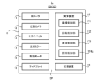
- FIG. 3 is a block diagram showing the configuration of an imaging unit included in the information processing system according to the second embodiment.
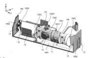
- FIG. 4 is a perspective view showing the appearance of an imaging unit according to the second embodiment.
- FIG. 5 is a perspective view showing the appearance of an imaging unit according to the second embodiment.
- FIG. 6 is a cross-sectional view showing the layout of the face camera, iris camera, LED units, reflecting mirrors, and drive motors in the second embodiment.
- FIG. 1 is a block diagram showing the configuration of an information processing system according to the first embodiment.
- FIG. 2 is a block diagram showing the overall configuration of an information processing system according to the second embodiment.
- FIG. 3 is a block diagram showing the configuration of an imaging unit included in the information processing system according to the second embodiment.
- FIG. 4 is a perspective view showing the appearance
- FIG. 7 is a cross section showing the layout of the face camera, iris camera, LED unit, reflection mirror, and drive motor in the second embodiment, with the face camera, iris camera, LED unit, reflection mirror, and drive motor separated from each other. It is a diagram.
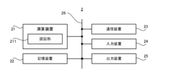
- FIG. 8 is a block diagram showing the configuration of an authentication server according to the second embodiment.
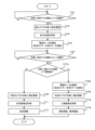
- FIG. 9 is a flow chart showing the flow of the imaging operation performed by the imaging unit and the authentication operation performed by the authentication server.
- FIG. 10 is a block diagram showing the configuration of an imaging unit according to the third embodiment.
- FIG. 11 is a flow chart showing the flow of operations for changing the intensity of illumination light in the third embodiment.
- FIG. 12 is a cross-sectional view showing the rotation angle of the camera cover.
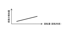
- FIG. 13 is a graph showing the relationship between the rotation angle and the intensity of illumination light.
- FIG. 14 is a cross-sectional view showing illumination light passing through the optical member filling the opening of the housing.
- FIG. 15 is a block diagram showing the configuration of an imaging unit according to the fourth embodiment.
- FIG. 16 is a flow chart showing the flow of operations for changing the brightness of the iris image in the fourth embodiment.
- FIG. 17 is a graph showing the relationship between the rotation angle and the luminance change amount of the iris image.
- FIG. 18 is a block diagram showing the configuration of an imaging unit according to the fifth embodiment.
- FIG. 19 is a cross-sectional view showing the respective rotation angles of the face camera, iris camera and reflection mirror.
- FIG. 20 is a block diagram showing the configuration of an imaging unit according to the sixth embodiment.
- FIG. 21 is a flow chart showing the flow of body temperature determination operation in the sixth embodiment.
- FIG. 22 is a flow chart showing the flow of imaging operation and authentication operation in the seventh embodiment.
- FIG. 1 is a block diagram showing the configuration of an information processing system SYS1 according to the first embodiment.
- the information processing system SYS1 includes an information processing device 1010 and an authentication device 1020.
- the information processing apparatus 1010 includes a first imaging unit 1011, which is a specific example of "first imaging means” described in the appendix to be described later, and a specific example of "second imaging means” described in the appendix to be described later.
- a driving unit 1015 which is a specific example of the “driving means” described in the appendix to be described later.
- the authentication device 1020 includes an authentication unit 1021, which is a specific example of "authentication means” described in the appendix to be described later.
- the information processing device 1010 may also be called an imaging device.
- the first imaging unit 1011 can image an object.
- the first imaging unit 1011 may be capable of generating the first image by imaging the target.
- the second imaging unit 1012 is also capable of imaging the target.
- the second imaging unit 1012 may be capable of generating the second image by imaging the target.
- the first imaging unit 1011 may image the first part of the target, and the second imaging unit 1012 may image the second part of the target.
- the first part of the object imaged by the first imaging unit 1011 may typically be different from the second part of the object imaged by the second imaging unit 1012 .
- the first part of the target imaged by the first imaging unit 1011 may include the second part of the target imaged by the second imaging unit 1012 .
- the second part of the target imaged by the second imaging unit 1012 may be a part included in the first part of the target imaged by the first imaging unit 1011 .
- the first region of the target imaged by the first imaging unit 1011 may be the same as the second region of the target imaged by the second imaging unit 1012 .
- the target is typically a person. However, the target is not limited to a person.
- the illumination unit 1013 emits illumination light.
- the reflecting unit 1014 reflects the illumination light emitted from the illumination unit 1013 toward the target.
- the object is irradiated with the illumination light reflected by the reflecting part 1014 . That is, the illumination unit 1013 illuminates the target with illumination light through the reflection unit 1014 .
- the illumination unit 1013 may illuminate the target with illumination light during at least part of the period in which the first imaging unit 1011 captures the image of the target.
- the first imaging unit 1011 may capture an image of an object illuminated with illumination light.
- return light for example, at least one of reflected light and scattered light
- the first imaging unit 1011 may capture an image of the target by receiving return light of illumination light from the target.
- the illumination unit 1013 may illuminate the target with illumination light during at least part of the period in which the second imaging unit 1012 images the target.
- the second imaging unit 1012 may capture an image of an object illuminated with illumination light.
- return light for example, at least one of reflected light and scattered light
- the second imaging unit 1012 may capture an image of the target by receiving return light of illumination light from the target.
- the drive unit 1015 is arranged at a position different from the position where the illumination unit 1013 is arranged.
- the drive unit 1015 drives the first imaging unit 1011, the second imaging unit 1012, and the reflection unit 1014, respectively.
- the driving unit 1015 moves the first imaging unit 1011, the second imaging unit 1012, and the reflecting unit 1014, respectively.
- driving section 1015 does not have to drive lighting section 1013 .
- the drive unit 1015 does not have to move the lighting unit 1013 .
- illumination unit 1013 may be fixed.
- the authentication unit 1021 authenticates the target. Therefore, each of the first imaging unit 1011 and the second imaging unit 1012 captures an image of the target to be authenticated by the authentication unit 1021 .
- the authentication unit 1021 uses at least one of a first image generated by imaging the target by the first imaging unit 1011 and a second image generated by imaging the target by the second imaging unit 1012 to identify the target. to authenticate.
- the authentication unit 1021 may perform face authentication for authenticating the target using the face image. good.
- the second imaging unit 1012 captures the iris of the target and generates the iris image as the second image
- the authentication unit 1021 performs iris authentication for authenticating the target using the iris image. may
- the drive unit 1015 drives the first imaging unit 1011, the second imaging unit 1012, and the reflection unit 1014, but does not drive the illumination unit 1013. good too.
- the wiring connected to the illumination unit 1013 is reduced.
- the first imaging unit 1011, the second imaging unit 1012, and the reflection unit 1014 are less likely to be disconnected. Therefore, the information processing apparatus 1010 of the first embodiment can solve the first technical problem that the wiring connected to the lighting unit 1013 may be disconnected.
- the illumination unit 1013 does not have to be driven together with the first imaging unit 1011, the second imaging unit 1012, and the reflection unit 1014 driven by the driving unit 1015. . Therefore, in the first embodiment, the lighting unit 1013 can be arranged at a position distant from each of the first imaging unit 1011, the second imaging unit 1012, and the reflecting unit 1014, as compared with the first comparative example. As a result, in the first embodiment, as compared with the first comparative example, the heat generated in the illumination unit 1013 due to the emission of the illumination light is distributed to the first imaging unit 1011, the second imaging unit 1012, and the reflection unit 1014. difficult to communicate to each other.
- the heat of the illumination unit 1013 affects each of the first imaging unit 1011, the second imaging unit 1012, and the reflection unit 1014 less than in the first comparative example. Therefore, in the information processing apparatus 1010 of the first embodiment, there is a possibility that each of the first imaging unit 1011, the second imaging unit 1012, and the reflecting unit 1014 will not operate normally due to the influence of the heat of the illumination unit 1013. It is possible to solve the second technical problem that there is.
- the information processing device 1010 may include another drive unit that drives the illumination unit 1013.
- another drive unit may drive the lighting unit 1013 in accordance with the driving of the reflection unit 1014 by the drive unit 1015 .
- another drive unit may drive the illumination unit 1013 in the same direction as the drive unit 1015 drives the reflection unit 1014 .
- another drive unit may drive the illumination unit 1013 upward when the drive unit 1015 drives the reflection unit 1014 upward.
- FIG. 2 is a block diagram showing the overall configuration of an information processing system SYS2 according to the second embodiment.
- the information processing system SYS2 includes an imaging unit 1 and an authentication server 2.
- the imaging unit 1 may be regarded as a specific example of the "information processing apparatus" described in the appendix to be described later.
- the imaging unit 1 may also be called an information processing device or an information processing unit.
- the authentication server 2 may be regarded as a specific example of the "authentication device” described in the appendix to be described later.
- the information processing system SYS2 may be called an authentication system.
- the imaging unit 1 performs an imaging operation of imaging at least part of the object.
- An object may include, for example, a person.
- the target may include animals other than humans (for example, at least one of mammals such as dogs and cats, birds such as sparrows, reptiles such as snakes, amphibians such as frogs, and fish such as goldfish).
- Objects may include inanimate objects. Inanimate objects may include robots that resemble humans or animals. In the following description, an example in which the target is a person will be described. For this reason, the target is hereinafter referred to as a “target person P”.
- the imaging unit 1 can generate a person image IMG in which at least part of the target person P is captured. Specifically, the imaging unit 1 captures the face of the target person P using a face camera 11 (see FIG. 3), which will be described later. It can be generated as an IMG. Furthermore, the imaging unit 1 uses an iris camera 12 (see FIG. 3), which will be described later, to image the eyes (especially the iris) of the target person P, so that the eyes (especially the iris) of the target person P are captured.
- the iris image IMG_I can be generated as a person image IMG.
- the iris image IMG_I may include a part of the target person P that is different from the iris. Even in this case, since the target person P is authenticated using the iris of the target person P reflected in the iris image IMG_I, as will be described in detail later, the part of the target person P that is different from the iris is displayed in the iris image. Even if it is reflected in IMG_I, no problem will occur. Alternatively, when a part of the target person P different from the iris is captured in the iris image IMG_I, but the iris of the target person P is not captured, the imaging unit 1 uses an iris camera as will be described in detail later.
- the imaging unit 1 rotates the iris camera 12 in the tilt direction (that is, rotationally moves) so that the iris of the target person P is included in the imaging range of the iris camera 12, thereby capturing the image of the target person P.
- An iris image IMG_I in which the iris is reflected may be generated.
- the face image IMG_F may include parts of the target person P that are different from the face. Even in this case, as will be described later, the position of the eyes of the target person P is identified using the face of the target person P reflected in the face image IMG_F. Even if the part is reflected in the face image IMG_F, no problem occurs.
- the imaging unit 1 uses the face camera as will be described in detail later. 11 may be moved (that is, driven) to generate a face image IMG_F in which the face of the target person P is captured.
- the imaging unit 1 rotates the face camera 11 in the tilt direction (that is, rotationally moves) so that the face of the target person P is included in the imaging range of the face camera 11, thereby capturing the image of the target person P.
- a face image IMG_F in which the face is captured may be generated.
- the authentication server 2 acquires the person image IMG from the imaging unit 1 and performs an authentication operation for authenticating the target person P using the person image IMG.
- the authentication server 2 acquires the iris image IMG_I from the imaging unit 1 and uses the iris image IMG_I to perform an authentication operation for authenticating the target person P. That is, the authentication server 2 performs an authentication operation related to iris authentication. Specifically, based on the iris pattern of the target person P appearing in the acquired iris image IMG_I, the authentication server 2 determines whether the target person P appearing in the acquired iris image IMG_I is registered in advance. It is determined whether or not it is the same as a person (hereinafter referred to as "registered person").
- the target person P appearing in the iris image IMG_I is the same as the registered person, it is determined that the target person P has been successfully authenticated. On the other hand, if it is determined that the target person P appearing in the iris image IMG_I is not the same as the registered person, it is determined that the authentication of the target person P has failed.
- Such an information processing system SYS2 is, for example, an object to an entry-restricted area in which a target person P who satisfies a predetermined entry condition is permitted to enter, while a target person P who does not satisfy the predetermined admission condition is not permitted to enter. It may be used to manage the entrance of person P.
- the imaging unit 1 may be arranged at the entrance of the entry restricted area.
- the iris camera 12 may take an image of the target person P who is about to enter the entry restricted area.
- the authentication server 2 may determine, based on the iris image IMG_I, whether or not the target person P is the same as a registered person who satisfies the entry conditions.
- the target person P may be permitted to enter the restricted entry area.
- the authentication server 2 may set the state of the gate device installed at the entrance of the entry-restricted area to an open state in which the gate device does not prevent the target person P from passing through.
- the target person P may be prohibited from entering the restricted entry area.
- the authentication server 2 may set the state of the gate device installed at the entrance of the entry-restricted area to a closed state in which the gate device prevents the target person P from passing through.
- Such an information processing system SYS2 may be used, for example, to manage payment for goods or services by the target person P.
- the imaging unit 1 may be arranged at a place (for example, a checkout counter) where the target person P settles the payment for the product or service.
- the iris camera 12 may image the target person P for whom the consideration is to be paid.
- the authentication server 2 may determine whether or not the target person P is the same as the registered person whose settlement method is associated in advance, based on the iris image IMG_I. If the target person P is the same as the registered person, the authentication server 2 may complete the settlement of the consideration using the associated settlement method. On the other hand, if the target person P is not the same as the registered person, the authentication server 2 does not have to complete the settlement of the consideration using the associated settlement method.
- FIG. 3 is a block diagram showing the configuration of the imaging unit 1. As shown in FIG.
- the imaging unit 1 includes a face camera 11, an iris camera 12, an LED (Light Emitting Diode) unit 13, a reflecting mirror 14, a drive motor 15, a display 16, and an arithmetic device 17. , and a storage device 18 .
- the face camera 11 is a specific example of the "first imaging means” described in the appendix to be described later.
- the iris camera 12 is a specific example of the “second imaging means” described in the appendix to be described later.
- the LED unit 13 is a specific example of the "illumination means” described in the appendix to be described later.
- the reflecting mirror 14 is a specific example of the "reflecting means” described in the appendix to be described later.
- the drive motor 15 is a specific example of the "driving means” described in the appendix to be described later.
- the face camera 11 is an information processing device capable of imaging the face of the target person P.
- the face camera 11 can typically capture at least part of the target person P including the target person's P face.
- the face camera 11 can generate a face image IMG_F in which the face of the target person P is captured by capturing an image of the target person P's face.
- the iris camera 12 is an information processing device capable of capturing at least the eyes (especially the iris) of the target person P.
- the iris camera 12 can typically capture at least part of the target person P including the target person's P eyes.
- the iris camera 12 can generate an iris image IMG_I in which the eyes (especially the iris) of the target person P are captured by capturing the eye of the target person P.
- the LED unit 13 emits illumination light.
- the illumination light is light for illuminating the target person P.
- the illumination light may include light for illuminating the target person P's face.
- the face camera 11 may capture the face of the target person P illuminated by the illumination light from the LED unit 13 .
- the illumination light may include light for illuminating the target person P's eyes (particularly, the iris).
- the iris camera 12 may image the eyes of the target person P illuminated by the illumination light from the LED unit 13 .
- the illumination light includes light for illuminating the eyes of the target person P. That is, in the following description, an example in which the LED unit 13 emits illumination light for illuminating the eyes of the target person P will be described.
- Near-infrared light is typically used as illumination light for illuminating the eyes. This is because there is a possibility that the target person P will feel glare if the target person P's eyes are irradiated with the visible light as the illumination light.
- the near-infrared light may include light whose wavelength is included in the near-infrared wavelength band. However, light different from near-infrared light (for example, visible light) may be used as illumination light.
- the reflecting mirror 14 is an optical element that reflects the illumination light emitted by the LED unit 13 toward the target person P. Therefore, in the second embodiment, the LED unit 13 illuminates the target person P with illumination light via the reflecting mirror 14 . Since the LED unit 13 illuminates the eyes of the target person P with illumination light as described above, the reflection mirror 14 reflects the illumination light emitted by the LED unit 13 toward the eyes of the target person P.
- the returned light may include reflected light of illumination light (that is, light reflected by the eyes of the target person P).
- the returned light may include scattered light of illumination light (that is, light scattered by the eyes of the target person P).
- the iris camera 12 captures an image of the eyes of the target person P by receiving return light. Therefore, the iris camera 12 may include an imaging device that receives the returned light.
- An example of the imaging device is a CCD (Charge Coupled Device) or a CMOS (Complementary Metal Oxide Semiconductor).
- the driving motor 15 is a driving device for driving (that is, moving) the face camera 11, the iris camera 12 and the reflecting mirror 14 under the control of the computing device 17.
- the drive motor 15 rotates (that is, rotates) the face camera 11, the iris camera 12, and the reflection mirror 14 around a predetermined rotation axis.
- the drive motor 15 may rotate the face camera 11 so that the face camera 11 can appropriately image the face of the target person P.
- the drive motor 15 rotates the iris camera 12
- the imaging range of the iris camera 12 moves. Therefore, the drive motor 15 may rotate the iris camera 12 so that the iris camera 12 can properly image the eyes of the target person P.
- the driving motor 15 rotates the reflecting mirror 14, the irradiation position of the illumination light via the reflecting mirror 14 changes. Therefore, the driving motor 15 may rotate the reflecting mirror 14 so that the eye of the target person P is irradiated with the illumination light.
- the display 16 is a display device capable of displaying desired information.
- the display 16 may be able to display information regarding authentication of the target person P using the iris image IMG_I.
- the information on authentication of the target person P may include information on the authentication result of the target person P.
- Information related to the authentication of the target person P is information to be notified to the target person P who has been successfully authenticated (for example, information to notify the target person P that he/she has been permitted to enter the entrance-restricted area described above). may contain
- the information about the authentication of the target person P includes information to be notified to the target person P whose authentication has failed (for example, information to notify the next action that the target person P should perform because the authentication has failed). You can
- the imaging unit 1 may include any output device capable of outputting desired information.
- the imaging unit 1 may include an audio output device (for example, a speaker) capable of outputting desired information as audio.
- the imaging unit 1 may include a paper output device (for example, a printer) capable of outputting paper on which desired information is written.
- the computing device 17 includes, for example, at least one of a CPU (Central Processing Unit), a GPU (Graphics Processing Unit), and an FPGA (Field Programmable Gate Array). Arithmetic device 17 reads a computer program. For example, arithmetic device 17 may read a computer program stored in storage device 18 . For example, the computing device 17 may read a computer program stored in a computer-readable non-temporary recording medium using a recording medium reading device (not shown) included in the imaging unit 1 . The computing device 17 may acquire (that is, download or read) a computer program from a device (not shown) arranged outside the imaging unit 1 via a communication device (not shown). Arithmetic device 17 executes the read computer program.
- a CPU Central Processing Unit
- GPU Graphics Processing Unit
- FPGA Field Programmable Gate Array
- logical functional blocks for executing the operations (for example, the above-described imaging operation) that should be performed by the imaging unit 1 are realized in the arithmetic unit 17 .
- the arithmetic device 17 can function as a controller for realizing logical functional blocks for executing the operations (in other words, processing) that the imaging unit 1 should perform.
- FIG. 3 shows an example of logical functional blocks implemented within the arithmetic device 17 to perform imaging operations.
- an imaging control section 171 controls the face camera 11 and the iris camera 12 so that the face camera 11 and the iris camera 12 respectively take an image of the target person P.
- the rotation control unit 172 controls the drive motor 15 to rotate the face camera 11, the iris camera 12, and the reflection mirror 14.
- FIG. The rotation control unit 172 is a specific example of "drive control means" described in the appendix to be described later.
- the display control unit 173 controls the display 16 to display desired information.
- the storage device 18 can store desired data.
- the storage device 18 may temporarily store computer programs executed by the arithmetic device 17 .
- the storage device 18 may temporarily store data that is temporarily used by the arithmetic device 17 while the arithmetic device 17 is executing a computer program.
- the storage device 18 may store data that the imaging unit 1 saves over a long period of time.
- the storage device 18 may include at least one of RAM (Random Access Memory), ROM (Read Only Memory), hard disk device, magneto-optical disk device, SSD (Solid State Drive), and disk array device. good. That is, storage device 18 may include non-transitory recording media.
- the face camera 11, the iris camera 12, the LED unit 13, the reflecting mirror 14, the drive motor 15, the display 16, the computing device 17 and the storage device 18 are arranged inside the housing 19. That is, the face camera 11 , iris camera 12 , LED unit 13 , reflecting mirror 14 , drive motor 15 , display 16 , computing device 17 and storage device 18 are housed in housing space SP inside housing 19 . However, at least one of the face camera 11, the iris camera 12, the LED unit 13, the reflecting mirror 14, the drive motor 15, the display 16, the arithmetic device 17, and the storage device 18 may not be arranged inside the housing 19. .
- the housing 19 may include a front housing 191 and a rear housing 192, as shown in FIG.
- the housing space SP may be formed between the front housing 191 and the rear housing 192 by combining the front housing 191 and the rear housing 192 twice this amount.
- the face camera 11, iris camera 12, LED unit 13, reflecting mirror 14, driving motor 15, display 16, computing device 17 and storage device 18 may be arranged in this accommodation space SP.
- the display 16 is housed in the housing 19 so that a display surface 161 capable of displaying information is exposed to the outside of the housing 19.
- the display 16 is mounted on the housing 19 so that the display surface 161 of the display 16 is exposed to the outside of the housing 19 through an opening 193 formed in the housing 19 (for example, the front housing 191). are housed in That is, the display 16 is housed in the housing 19 so that the display surface 161 can be viewed from the outside of the housing 19 through the opening 193 .
- the face camera 11, the iris camera 12, the LED unit 13, the reflecting mirror 14, the driving motor 15, the computing device 17, and the storage device 18 are accommodated in the housing 19 so as to be visible from the outside of the housing 19. It does not have to be.
- the face camera 11, the iris camera 12, the LED unit 13, the reflecting mirror 14, the driving motor 15, the arithmetic device 17, and the storage device 18 are housed in the housing 19 so as not to be visible from the outside of the housing 19. good.
- the housing 19 may be formed with an opening 194 that can be used by the face camera 11 to capture an image of the target person P's face.
- light for example, visible light
- the face camera 11 may capture the face of the target person P by receiving light incident on the face camera 11 through the opening 194 .
- the LED unit 13 illuminates the eyes of the target person P with illumination light
- the iris camera 12 receives return light from the target person P illuminated with the illumination light
- the housing 19 is formed with an opening 195 for the LED unit 13 to illuminate the eyes of the target person P with illumination light and for the iris camera 12 to receive return light from the eyes of the target person P.
- the LED unit 13 may emit illumination light toward the eyes of the target person P through the opening 195 .
- the iris camera 12 may capture the eye of the target person P by receiving light incident on the iris camera 12 through the aperture 195 .
- the aperture 195 is filled with an optical member 1951 that allows near-infrared light to pass through but absorbs or reflects part of visible light. may have been
- the aperture 195 may be filled with an optical member 1951 that allows near-infrared light to pass through and presents a desired color to visible light.
- the design of the exterior of the housing 19 that is, the design of the exterior of the imaging unit 1 is improved.
- the line of sight of the target person P can be easily guided to the display 16 exposed to the outside of the imaging unit 1 .
- the face camera 11, the iris camera 12, the LED unit 13, the reflecting mirror 14, and the drive motor 15 are connected via a common unit base 190 (see FIGS. 6 to 7).
- the face camera 11, the iris camera 12, the LED unit 13, the reflecting mirror 14, and the drive motor 15 may be arranged inside the housing 19 in the form of an integrated unit IU1.
- the integrated unit IU1 may be arranged near the openings 194 and 195 inside the housing space SP inside the housing 19 .
- the arithmetic device 17 and the storage device 18 are arranged inside the housing 19 in the form of an integrated unit IU2 in which the arithmetic device 17 and the storage device 18 are integrated via a common unit base (not shown).
- the integrated unit IU2 may be arranged behind the display 16 within the accommodation space SP inside the housing 19 .
- the arrangement method of the face camera 11, the iris camera 12, the LED unit 13, the reflecting mirror 14, the drive motor 15, the display 16, the arithmetic device 17 and the storage device 18 is not limited to the example shown in FIG.
- the imaging unit 1 may include a heat dissipation member capable of dissipating heat from the housing space SP inside the housing 19 to the outside of the housing 19 .
- a heat dissipation member capable of dissipating heat from the housing space SP inside the housing 19 to the outside of the housing 19 .
- the imaging unit 1 may include a heat dissipation member that promotes heat dissipation from at least one of the integrated unit IU1 and the integrated unit IU2.
- heat is generated from at least one of the face camera 11, the iris camera 12, the LED unit 13, the reflecting mirror 14, the drive motor 15, the display 16, the arithmetic device 17, and the storage device 18 housed in the housing space SP. may occur.
- the imaging unit 1 includes a heat dissipation member that promotes heat dissipation from at least one of the face camera 11, the iris camera 12, the LED unit 13, the reflecting mirror 14, the drive motor 15, the display 16, the arithmetic device 17, and the storage device 18.
- part of the housing 19 may be used as a heat dissipation member.
- the vicinity portion 196 positioned in the vicinity of the integrated unit IU1 in the housing 19 is used as a heat radiation member for promoting heat radiation from the integrated unit IU1.
- a member different from the housing 19 may be used as the heat dissipation member.
- a heat sink HS attached in the vicinity of the integrated unit IU2 in the housing 19 may be used as a heat radiating member for promoting heat radiation from the integrated unit IU2.
- FIGS. An example of arrangement of the face camera 11, the iris camera 12, the LED unit 13, the reflecting mirror 14, and the driving motor 15 (that is, the configuration of the integrated unit IU1) will be described.
- FIG. 6 is a perspective view showing an example of arrangement of the face camera 11, the iris camera 12, the LED unit 13, the reflecting mirror 14, and the drive motor 15.
- FIG. 7 shows an example of arrangement of the face camera 11, the iris camera 12, the LED unit 13, the reflecting mirror 14, and the drive motor 15.
- Fig. 3 is a perspective view, shown separated from each other;
- the layout of the face camera 11, the iris camera 12, the LED unit 13, the reflecting mirror 14, and the drive motor 15 shown in FIGS. 6 and 7 is merely an example. Therefore, the layout of the face camera 11, the iris camera 12, the LED unit 13, the reflecting mirror 14, and the drive motor 15 is not limited to the examples shown in FIGS.
- the unit base 190 includes a plate-like bottom member 1901 along the XY plane, and a pair of plate-like side wall members 1902 extending upward from both ends of the bottom member 1901 along the Z-axis direction.
- the X-axis and Y-axis in FIGS. 6 and 7 may be horizontal axes orthogonal to each other.
- the Z-axis in FIGS. 6 and 7 may be a vertical axis orthogonal to the X-axis and Y-axis.
- a drive motor 15 is attached to the bottom member 1901 .
- a camera base 151 is attached to the rotary shaft 150 of the drive motor 15 . Therefore, the camera base 151 is rotatable around the rotation shaft 150 of the drive motor 15 by the drive motor 15 . That is, the camera base 151 is rotatable around a predetermined rotation axis that defines the center of rotation of the rotation shaft 150 of the drive motor 15 .
- the rotation axis of the camera base 151 extends along the direction in which the rotation shaft 150 of the drive motor 15 extends. 6 and 7, the rotating shaft of the drive motor 15 (that is, the rotating shaft of the camera base 151) is parallel to the X-axis.
- a face camera 11 and an iris camera 12 are attached to the camera base 151 .
- the face camera 11 and the iris camera 12 are attached to the camera base 151 so that the face camera 11 and the iris camera 12 are aligned along the rotation axis. Therefore, each of the face camera 11 and the iris camera 12 can be rotated around the rotation axis of the camera base 151 by the drive motor 15 .
- the face camera 11 is attached to the camera base 151 so that the optical axis of the face camera 11 (for example, the optical axis of an optical system such as a lens) intersects the rotation axis of the camera base 151 .
- the iris camera 12 is attached to the camera base 151 so that the optical axis of the iris camera 12 (for example, the optical axis of an optical system such as a lens) intersects the rotation axis of the camera base 151 . Therefore, the drive motor 15 can rotate each of the face camera 11 and the iris camera 12 in the tilt direction. In other words, the drive motor 15 can rotate the face camera 11 and the iris camera 12 so that the respective imaging ranges of the face camera 11 and the iris camera 12 move in the vertical direction.
- the face camera 11 moves the imaging range in the vertical direction to capture the face of the target person P. It can be imaged properly.
- the iris camera 12 moves the imaging range in the vertical direction so that the eyes of the target person P ( In particular, the iris) can be appropriately imaged.
- a camera cover 152 is further attached to the camera base 151 .
- Camera cover 152 is a member for partially covering face camera 11 and iris camera 12 .
- the camera cover 152 includes a cover member 1521 that partially covers the face camera 11 and a cover member 1522 that partially covers the iris camera 12 .
- the cover member 1521 may be formed with an opening 15211 through which light incident on the face camera 11 from the target person P can pass.
- the cover member 1522 may be formed with an opening 15221 through which return light incident on the iris camera 12 from the target person P can pass.
- Camera cover 152 may further include a cover member 1523 for partially covering drive motor 15 .
- a reflecting mirror 14 is attached to the camera cover 152 . Therefore, the reflecting mirror 14 can be rotated around the rotation axis of the camera base 151 by the drive motor 15 .
- each of both ends of the camera cover 152 functions as a mirror mounting member 1524 to which the reflecting mirror 14 can be mounted. Therefore, in the second embodiment, the imaging unit 1 has a pair of reflecting mirrors 14 attached to both ends of the camera cover 152, respectively.
- Reflecting mirror 14 is attached to camera cover 152 (especially mirror mounting member 1524 ) so that reflecting mirror 14 intersects the rotational axis of camera base 151 .
- the reflecting mirror 14 is attached to the camera cover 152 (particularly, the mirror mounting member 1524 ) so that the rotation axis of the camera base 151 becomes an axis that can pass through the reflecting mirror 14 .
- the side wall member 1902 is attached with the LED unit 13 . That is, the LED unit 13 is attached to a member different from the bottom member 1901 to which the face camera 11, iris camera 12, reflection mirror 14 and drive motor 15 are attached. The LED unit 13 is arranged at a position different from the positions where the face camera 11, the iris camera 12, the reflecting mirror 14 and the driving motor 15 are arranged. The LED unit 13 is arranged at a position away from the positions where the face camera 11, the iris camera 12, the reflecting mirror 14 and the driving motor 15 are arranged. Therefore, the drive motor 15 does not have to rotate the LED unit 13 .
- the LED unit 13 may be fixed to the side wall member 1902 . The LED unit 13 does not have to be movable.
- a pair of LED units 13 are attached to the pair of side wall members 1902, respectively.
- a camera base 151 and a camera cover 152 are arranged between the pair of side wall members 1902 .
- the pair of LED units 13 are attached to the pair of side wall members 1902 so that the pair of LED units 13 emit illumination light toward the pair of reflecting mirrors 14 attached to both ends of the camera cover 152 respectively. That is, the pair of LED units 13 are arranged so as to face a direction different from the direction of the target person P instead of facing the direction of the target person P.
- the pair of LED units 13 are arranged so as to emit illumination light in a direction different from the direction of the target person P instead of directly emitting the illumination light in the direction of the target person P. be.
- the LED unit 13 is less likely to be seen from the outside of the image pickup unit 1, so the design of the image pickup unit 1 is improved.
- the reflecting mirror 14 is attached to the camera cover 152 so that the reflecting mirror 14 can reflect the illumination light emitted from the LED unit 13 toward the target person P.
- the driving motor 15 rotates the reflecting mirror 14
- the irradiation position of the illumination light emitted from the LED unit 13 toward the target person P via the reflecting mirror 14 moves in the vertical direction. Therefore, even if the position of the eyes of the target person P changes in the vertical direction depending on the height of the target person P, the LED unit 13 uses the reflecting mirror 14 to move the irradiation position of the illumination light in the vertical direction.
- the eyes (especially the iris) of the target person P can be appropriately illuminated with the illumination light.
- the iris camera 12 , the reflecting mirror 14 and the LED unit 13 are configured such that even when the drive motor 15 rotates the iris camera 12 and the reflecting mirror 14 , the illumination light emitted from the LED unit 13 does not move the reflecting mirror 14 . It is preferable that the iris of the target person P is irradiated through the iris and the return light from the iris of the target person P is incident on the iris camera 12 in advance. In other words, even if drive motor 15 rotates iris camera 12 and reflecting mirror 14 , the positional relationship among iris camera 12 , reflecting mirror 14 and LED unit 13 may vary depending on the illumination emitted from LED unit 13 . It is preferable to maintain an ideal positional relationship in which light is irradiated onto the iris of the target person P via the reflecting mirror 14 and return light from the iris of the target person P is incident on the iris camera 12 .
- the LED unit 13 may be attached to the side wall member 1902 so that the optical axis of the LED unit 13 is coaxial with the rotating shaft 150 of the drive motor 15.
- the LED unit 13 may be attached to the side wall member 1902 so that the optical axis of the LED unit 13 is coaxial with the rotation axis of the camera base 151 .
- the "optical axis of the LED unit 13" in the second embodiment may mean the central axis of the light beam when the illumination light emitted from the LED unit 13 is regarded as one light beam.
- the "optical axis of the LED unit 13" in the second embodiment means an axis extending along the principal ray of the light beam when the illumination light emitted from the LED unit 13 is regarded as one light beam. good.
- FIG. 8 is a block diagram showing the configuration of the authentication server 2. As shown in FIG.
- the authentication server 2 includes an arithmetic device 21, a storage device 22, and a communication device 23. Further, the authentication server 2 may have an input device 24 and an output device 25 . However, the authentication server 2 does not have to include at least one of the input device 24 and the output device 25 . Arithmetic device 21 , storage device 22 , communication device 23 , input device 24 and output device 25 may be connected via data bus 26 .
- the arithmetic unit 21 includes, for example, a CPU (Central Processing Unit), a GPU (Graphics Processing Unit), an FPGA (Field Programmable Gate Array), a DSP (Demand-Side Platform), and an ASIC (Application Specific In at least one of the integrated circuits) including.
- Arithmetic device 21 reads a computer program.
- arithmetic device 21 may read a computer program stored in storage device 22 .
- the computing device 21 may read a computer program stored in a computer-readable non-temporary recording medium using a recording medium reading device (not shown) provided in the authentication server 2 .
- the computing device 21 may acquire (that is, download) a computer program from a device (not shown) arranged outside the authentication server 2 via the communication device 23 (or other communication device). or read). Arithmetic device 21 executes the read computer program. As a result, logical functional blocks for executing the operation (for example, the above-described authentication operation) that should be performed by the authentication server 2 are realized in the arithmetic device 21 . In other words, the computing device 21 can function as a controller for implementing logical functional blocks for executing the operations (in other words, processing) that the authentication server 2 should perform.
- FIG. 8 shows an example of logical functional blocks implemented within the computing device 21 to perform the authentication operation.
- an authentication unit 211 is implemented within the computing device 21 .
- the authentication unit 211 is a specific example of the “authentication means” in the appendix described later.
- the authentication unit 211 acquires the iris image IMG_I from the imaging unit 1 and authenticates the target person P based on the acquired iris image IMG_I.
- the storage device 22 can store desired data.
- the storage device 22 may temporarily store computer programs executed by the arithmetic device 21 .
- the storage device 22 may temporarily store data temporarily used by the arithmetic device 21 while the arithmetic device 21 is executing a computer program.
- the storage device 22 may store data that the authentication server 2 saves over a long period of time.
- the storage device 22 may include at least one of RAM (Random Access Memory), ROM (Read Only Memory), hard disk device, magneto-optical disk device, SSD (Solid State Drive), and disk array device. good. That is, the storage device 22 may include non-transitory recording media.
- the communication device 23 can communicate with the imaging unit 1 via a communication network (not shown). In the second embodiment, the communication device 23 receives (that is, acquires) the person image IMG (in particular, the iris image IMG_I) from the imaging unit 1 .
- the input device 24 is a device that accepts input of information to the authentication server 2 from outside the authentication server 2 .
- the input device 24 may include an operation device (for example, at least one of a keyboard, a mouse and a touch panel) that can be operated by an operator of the authentication server 2 .
- the input device 24 may include a reading device capable of reading information recorded as data on a recording medium externally attached to the authentication server 2 .
- the output device 25 is a device that outputs information to the outside of the authentication server 2 .
- the output device 25 may output information as an image.
- the output device 25 may include a display device (so-called display) capable of displaying an image showing information to be output.
- the output device 25 may output information as voice.
- the output device 25 may include an audio device capable of outputting audio (so-called speaker).
- the output device 25 may output information on paper. That is, the output device 25 may include a printing device (so-called printer) capable of printing desired information on paper.
- FIG. 9 is a flow chart showing the flow of the imaging operation performed by the imaging unit 1 and the authentication operation performed by the authentication server 2 .
- the imaging unit 1 performs an imaging operation (steps S101 to S106).
- the authentication server 2 performs an authentication operation (steps S111 to S112).
- the imaging control unit 171 of the imaging unit 1 determines whether or not the distance from the imaging unit 1 to the target person P is equal to or less than a predetermined trigger distance (step S101). For example, the imaging control unit 171 determines that the distance from the imaging unit 1 to the target person P is equal to or less than the trigger distance based on the detection result of a distance sensor (not shown) capable of detecting the distance from the imaging unit 1 to the target person P. It may be determined whether The trigger distance may be the distance from the imaging unit 1 to the position where the face camera 11 is focused (that is, the focal plane of the face camera 11).
- the operation of determining whether or not the distance from the imaging unit 1 to the target person P has become equal to or less than the trigger distance is to determine whether or not the target person P is positioned at a position where the face camera 11 is focused. Equivalent to action.
- step S101 when it is determined that the distance from the imaging unit 1 to the target person P is not equal to or less than the trigger distance (step S101: No), the imaging control unit 171 moves the imaging unit 1 to the target. It continues to determine whether or not the distance to the person P has become equal to or less than the trigger distance.
- step S101 when it is determined that the distance from the imaging unit 1 to the target person P is equal to or less than the trigger distance (step S101: Yes), the imaging control unit 171 The face camera 11 is controlled so as to capture an image of the face (step S102). As a result, the face camera 11 images the face of the target person P (step S102).
- the rotation control unit 172 acquires the face image IMG_F from the face camera 11, and based on the acquired face image IMG_F, the position of the eyes of the target person P (in particular, the position in the vertical direction, for example, the Z-axis direction). position) is specified (step S103).
- the rotation control unit 172 enables the reflection mirror 14 to reflect the illumination light emitted from the LED unit 13 toward the eye located at the position specified in step S103, and the iris camera 12 is enabled to reflect the illumination light emitted from the LED unit 13 in step S103.
- the drive motor 15 is controlled to rotate the iris camera 12 and the reflecting mirror 14 so that the return light from the eye located at the position specified in 1. can be received (step S104).
- the iris camera 12 becomes capable of imaging the eyes of the target person P illuminated by the illumination light.
- the imaging control unit 171 determines whether or not the distance from the imaging unit 1 to the target person P is equal to or less than a predetermined focus distance (step S105). For example, the imaging control unit 171 determines that the distance from the imaging unit 1 to the target person P is less than or equal to the focus distance based on the detection result of a distance sensor (not shown) capable of detecting the distance from the imaging unit 1 to the target person P. It may be determined whether The focus distance may be the distance from the imaging unit 1 to the position where the iris camera 12 is focused (that is, the focal plane of the iris camera 12).
- the operation of determining whether or not the distance from the imaging unit 1 to the target person P is equal to or less than the focus distance is to determine whether or not the target person P is positioned at a position where the iris camera 12 can focus. Equivalent to action. Note that the focus distance is typically less than the trigger distance discussed above.
- step S105 when it is determined that the distance from the imaging unit 1 to the target person P is not equal to or less than the focus distance (step S105: No), the imaging control unit 171 moves the imaging unit 1 to the target. It continues to determine whether or not the distance to the person P has become equal to or less than the focus distance.
- step S105 when it is determined that the distance from the imaging unit 1 to the target person P is equal to or less than the focus distance (step S105: Yes), the imaging control unit 171 The iris camera 12 is controlled so as to image the eye (especially the iris) (step S106). As a result, the iris camera 12 images the eyes of the target person P (step S106).
- the authentication server 2 starts the authentication operation (steps S111 to S112). Specifically, the authentication unit 211 of the authentication server 2 acquires the iris image IMG_I from the iris camera 12 via the communication device 23 (step S111). After that, the authentication unit 211 authenticates the target person P based on the iris image IMG_I acquired in step S111 (step S112).
- the authentication unit 211 may perform the operation that should be performed when the authentication of the target person P is successful. For example, when the information processing system SYS2 is used to manage the entry of the target person P into the entry-restricted area as described above, the authentication unit 211 may access the gate installed at the entrance of the entry-restricted area. The state of the device may be set to an open state in which the gate device does not prevent the target person P from passing. For example, as described above, when the information processing system SYS2 is used to manage payment for goods or services by the target person P, the authentication unit 211 uses the payment method associated with the target person P. You may complete the settlement of consideration.
- the authentication unit 211 may perform the operation that should be performed when the target person P is not successfully authenticated. For example, when the information processing system SYS2 is used to manage the entry of the target person P into the entry-restricted area as described above, the authentication unit 211 may access the gate installed at the entrance of the entry-restricted area. The state of the device may be set to a closed state in which the gate device prevents the target person P from passing. For example, as described above, when the information processing system SYS2 is used to manage payment for goods or services by the target person P, the authentication unit 211 uses the payment method associated with the target person P. It is not necessary to complete the payment of consideration.
- the drive motor 15 drives the face camera 11, the iris camera 12, and the reflection mirror 14, respectively.
- the LED unit 13 may not be rotated.
- the wiring connected to the LED unit 13 is , the possibility of disconnection due to rotation of the iris camera 12 and the reflection mirror 14 is reduced.
- the rotation of the face camera 11, the iris camera 12, and the reflection mirror 14 is generated with respect to the wiring connected to the LED unit 13.
- the imaging unit 1 of the second embodiment can solve the first technical problem that the wiring connected to the LED unit 13 may be disconnected.
- the wiring connected to the LED unit 13 can be shortened compared to when the LED unit 13 rotates.
- the weight of wiring connected to the LED unit 13 can be reduced. That is, the weight of the imaging unit 1 can be reduced.
- the LED unit 13 does not have to be rotated together with the face camera 11, iris camera 12, and reflecting mirror 14, which are rotated by the driving motor 15. Therefore, in the second embodiment, compared to the second comparative example in which the LED unit 13 is rotated together with each of the face camera 11, the iris camera 12, and the reflection mirror 14, the LED unit 13 has the face camera 11, the iris It can be arranged at a position away from each of the camera 12, the reflecting mirror 14 and the driving motor 15. - ⁇ That is, in the second embodiment, the LED unit 13 can be separated relatively far from each of the face camera 11, the iris camera 12, the reflecting mirror 14, and the drive motor 15, as compared with the second comparative example.
- the LED unit 13 can be arranged at a position different from the positions at which the face camera 11, the iris camera 12, the reflecting mirror 14, and the drive motor 15 are arranged. Specifically, the LED unit 13 is attached to a side wall member 1902 different from the bottom member 1901 to which the face camera 11, the iris camera 12 and the reflection mirror 14 are attached.
- the heat generated in the LED unit 13 due to the emission of illumination light is transmitted to each of the face camera 11, the iris camera 12, and the reflection mirror 14, as compared with the second comparative example. less likely to be Therefore, in the second embodiment, compared with the second comparative example, the influence of the heat of the LED unit 13 on each of the face camera 11, the iris camera 12, and the reflection mirror 14 is reduced.
- each of the face camera 11, the iris camera 12, and the reflection mirror 14 is affected by the heat generated due to the emission of the illumination light from the LED unit 13. It is more likely to be able to operate normally without being subjected to Therefore, the imaging unit 1 of the second embodiment has the second problem that each of the face camera 11, the iris camera 12, and the reflection mirror 14 may not operate normally due to the heat of the LED unit 13. Able to solve technical problems.
- the LED unit 13 irradiates the target person P with illumination light via the reflecting mirror 14 . Therefore, the LED unit 13 does not have to directly emit illumination light toward the target person P. As a result, the possibility that the LED unit 13 is visible from the outside of the imaging unit 1 is reduced. Therefore, the design of the imaging unit 1 is improved.
- the LED unit 13 since the LED unit 13 does not have to be rotated, the LED unit 13 can be arranged at a fixed position that is not driven by the drive motor 15. Therefore, in the second embodiment, compared to the second comparative example in which the LED unit 13 is rotated together with the face camera 11, the iris camera 12, and the reflection mirror 14, the face camera 11, the iris camera 12, and the reflection mirror 14 are rotated. and the LED unit 13 are less likely to deviate from the ideal positional relationship.
- the ideal positional relationship is such that even when the driving motor 15 rotates the iris camera 12 and the reflecting mirror 14, the positions of the iris camera 12, the reflecting mirror 14, and the LED unit 13 are The relationship is a positional relationship in which illumination light emitted from the LED unit 13 is irradiated onto the iris of the target person P via the reflecting mirror 14 and return light from the iris of the target person P is incident on the iris camera 12.
- the information processing apparatus described in the above-mentioned Patent Document 1 separately includes a motor for moving a camera that captures an image of an object and a motor for moving a lighting fixture that illuminates the object.
- the imaging unit 1 of the second embodiment reduces the possibility that the positional relationships between the face camera 11, iris camera 12, and reflecting mirror 14 and the LED unit 13 deviate from the ideal positional relationship. can be done. For this reason, in the imaging unit 1 of the second embodiment, the positional relationship between each of the face camera 11, iris camera 12, and reflecting mirror 14 and the LED unit 13 may deviate from the ideal positional relationship. 3 technical problems can be solved.
- the imaging unit 1 may include a heat dissipation member capable of dissipating the heat of the housing space SP inside the housing 19 to the outside of the housing 19 . Therefore, compared to the case where the image pickup unit 1 does not include a heat dissipation member, the image pickup unit 1 is less affected by heat generated in the housing space SP (for example, heat generated by devices housed in the housing space SP). less likely to receive. Therefore, the image pickup unit 1 can appropriately perform the image pickup operation without being affected by the heat generated in the housing space SP.
- the imaging unit 1 identifies the position of the eyes of the target person P based on the face image IMG_F, and the reflecting mirror 14 is positioned at the identified position of the illumination light emitted from the LED unit 13.
- the iris camera 12 and reflecting mirror 14 can be rotated so that the light is reflected toward the eye and the iris camera 12 is able to receive the return light from the eye located at the specified location. Therefore, even if the position of the eyes of the target person P changes in the vertical direction depending on the height of the target person P, the imaging unit 1 can appropriately illuminate the eyes of the target person P with the illumination light, The eye of the person P can be imaged appropriately.
- the imaging unit 1 can rotate the face camera 11, the iris camera 12, and the reflection mirror 14. For this reason, the imaging unit 1 moves the imaging range of the face camera 11 in the vertical direction, moves the imaging range of the iris camera 12 in the vertical direction, and moves the irradiation position of the illumination light reflected by the reflecting mirror 14 in the vertical direction. can be moved to Therefore, even if the positions of the face and eyes of the target person P change in the vertical direction due to the height of the target person P, the image capturing unit 1 can appropriately capture the image of the target person P's face. The eyes can be properly imaged and the eyes of the target person P can be properly illuminated with the illumination light.
- the LED unit 13 can be attached to the side wall member 1902 so that the optical axis of the LED unit 13 is coaxial with the rotation shaft 150 of the drive motor 15 (that is, the rotation axis of the camera base 151). be. Therefore, even when the driving motor 15 rotates the reflecting mirror 14 , the illumination light emitted from the LED unit 13 enters the reflecting mirror 14 . Therefore, the reflecting mirror 14 can emit illumination light toward the target person P from the reflecting mirror 14 even when the driving motor 15 rotates the reflecting mirror 14 . In this case, although the emission angle of the illumination light emitted from the reflection mirror 14 changes as the reflection mirror 14 rotates, the emission position of the illumination light emitted from the reflection mirror 14 does not change.
- the driving motor 15 rotates the iris camera 12 and the reflecting mirror 14
- the illumination light emitted from the LED unit 13 is irradiated onto the iris of the target person P via the reflecting mirror 14. more likely. That is, even when the driving motor 15 rotates the iris camera 12 and the reflecting mirror 14, the ideal positional relationship between the iris camera 12, the reflecting mirror 14, and the LED unit 13 can be easily maintained.
- the authentication unit 211 of the authentication server 2 performs the authentication operation when it is determined that the distance from the imaging unit 1 to the target person P is equal to or less than the focus distance. is starting. However, when the authentication unit 211 determines that the distance from the imaging unit 1 to the target person P is equal to or less than the focus distance, the authentication server 2 authenticates the target person P before starting the authentication operation. may be further determined whether or not the target person P agrees with. That is, the authentication unit 211 may further determine whether or not the target person P has an intention to allow the authentication server 2 to authenticate the target person P.
- the authentication unit 211 may start the authentication operation. On the other hand, when it is not determined that the target person P has an intention to allow the authentication server 2 to authenticate the target person P, the authentication unit 211 does not have to start the authentication operation.
- the authentication unit 211 causes the target person P to make a predetermined gesture indicating that the target person P has an intention to allow the authentication server 2 to authenticate the target person P based on the face image IMG_F. It may be determined whether or not An example of the predetermined gesture is a gesture that the target person P is looking at the imaging unit 1 . In this case, the authentication unit 211 determines whether or not the target person P is directing their line of sight to the imaging unit 1 by estimating the line of sight of the target person P based on the face image IMG_F using an existing line of sight estimation method. You may
- the authentication unit 211 may determine that the target person P has an intention to allow the authentication server 2 to authenticate the target person P when the iris image IMG_I is acquired. . This is because, when the iris image IMG_I is acquired, the target person P is looking at the iris camera 12, and therefore the target person P has an intention to allow the authentication server 2 to authenticate the target person P. This is because it is assumed to have If the iris image IMG_I is not acquired, the authentication unit 211 determines whether the target person P has an intention to allow the authentication server 2 to authenticate the target person P using another method.
- the authentication unit 211 determines whether the target person P has an intention to allow the authentication server 2 to authenticate the target person P based on the operation content of the target person P on the display 16 that can function as a touch panel. It may be determined that
- the authentication unit 211 displays a UI (User Interface) screen for asking the target person P whether or not the target person P has the intention to allow the authentication server 2 to authenticate the target person P.
- the display 16 of the imaging unit 1 may be controlled.
- the authentication unit 211 prompts the target person P to make a predetermined gesture indicating that the target person P has an intention to allow the authentication server 2 to authenticate the target person P.
- the display 16 may be controlled to display a UI screen for
- the authentication unit 211 allows the authentication server 2 to authenticate the target person P during at least part of the period in which the rotation control unit 172 controls the drive motor 15 to rotate the iris camera 12 and the reflecting mirror 14. It may be determined whether or not the target person P has the intention to allow. A certain amount of time is required for the rotation control unit 172 to control the drive motor 15 to rotate the iris camera 12 and the reflecting mirror 14. In order to effectively utilize this time, the authentication unit 211 is configured to operate during this time. , whether or not the target person P has an intention to allow the authentication server 2 to authenticate the target person P may be determined.
- the authentication unit 211 causes the display 16 to display a UI screen for informing the target person P that the authentication was successful. may be transmitted to the imaging unit 1 for controlling the .
- the authentication unit 211 may use a display method that protects the personal information of the target person P to display a UI screen for notifying the target person P that the authentication has succeeded.
- the authentication unit 211 may display a UI screen including an avatar set by the target person P as a UI screen for notifying the target person P that the authentication was successful.
- the imaging control unit 171 may control the display 16 to display a predetermined UI screen.
- the predetermined UI screen may include, for example, a screen prompting the target person P to face the face camera 11 .
- the predetermined UI screen may include, for example, a screen prompting the target person P to stand in front of the face camera 11 .
- the imaging control unit 171 causes the display 16 to display a predetermined UI screen.
- the predetermined UI screen may include, for example, a screen prompting the target person P to face the iris camera 12 .
- the predetermined UI screen may include, for example, a screen prompting the target person P to stand in front of the iris camera 12 .
- the predetermined UI screen may include, for example, a screen prompting the target person P to open their eyes wide.
- the predetermined UI screen includes a first image for widening the eyes of the target person P, and a second image (for example, An animation UI including a video imitating a flashlight using visible light) may be included.
- the authentication unit 211 determines whether or not the target person P has the intention to complete the payment. Further determination may be made. As an example, the authentication unit 211 acquires the face image IMG_F from the face camera 11 before completing the payment, and indicates that the target person P has the intention to complete the payment based on the face image IMG_F. It may be determined whether or not the target person P is making a predetermined gesture. Examples of predetermined gestures include at least one of blinking and nodding. At this time, the authentication unit 211 may control the display 16 to display a UI screen for inquiring of the target person P whether he/she has the intention to complete the payment. When it is determined that the target person P has the intention to complete the payment, the authentication unit 211 may complete the payment of the consideration. If it is not determined that the target person P has the intention to complete the payment, the authentication unit 211 does not have to complete the payment.
- predetermined gestures include at least one of blinking and nodding.
- the pair of reflecting mirrors 14 are arranged inside the pair of LED units 13 .
- the pair of LED units 13 may be arranged inside the pair of reflecting mirrors 14 . That is, the arrangement positions of the pair of LED units 13 and the arrangement positions of the pair of reflecting mirrors 14 may be reversed.
- the authentication server 2 authenticates the target person P using the iris image IMG_I.
- the authentication server 2 may authenticate the target person P using the iris image IMG_I and authenticate the target person P using the face image IMG_F. That is, the authentication server 2 may function as an authentication device having multimodal functions.
- the authentication server 2 may authenticate the target person P using the face image IMG_F without using the iris image IMG_I.
- the imaging unit 1 and the authentication server 2 are separate devices. However, the imaging unit 1 and the authentication server 2 may be integrated.
- the computing device 17 of the imaging unit 1 may include the authentication section 211 of the authentication server 2 .
- the computing device 21 of the authentication server 2 may include at least some of the processing blocks included in the computing device 17 of the imaging unit 1.
- the computing device 21 of the authentication server 2 may include at least one of the imaging control section 171, the rotation control section 172, and the display control section 173 included in the computing device 17 of the imaging unit 1.
- the computing device 17 of the imaging unit 1 may include at least part of the processing blocks included in the computing device 21 of the authentication server 2.
- the computing device 17 of the imaging unit 1 may include the authentication unit 211 included in the computing device 21 of the authentication server 2 .
- the information processing system SYS3 in the third embodiment differs from the information processing system SYS2 in the second embodiment described above in that it includes an imaging unit 1c instead of the imaging unit 1.
- FIG. Other features of the information processing system SYS3 may be the same as other features of the information processing system SYS2.
- FIG. 10 is a block diagram showing the configuration of an imaging unit 1c according to the third embodiment.
- the same reference numerals are assigned to the components that have already been described, and detailed description thereof will be omitted.
- the imaging unit 1c in the third embodiment differs from the imaging unit 1 in the second embodiment in that the arithmetic device 17 includes an illumination control section 174c.
- the illumination control unit 174c is a specific example of the "intensity control means" described in the appendix to be described later.
- Other features of imaging unit 1 c may be the same as other features of imaging unit 1 .
- the lighting control unit 174c changes the intensity of the illumination light emitted from the LED unit 13 based on the amount of rotation (that is, the amount of driving) of the camera base 151 by the drive motor 15.
- the amount of rotation of the camera base 151 is the same as that of the face camera 11, the iris camera 12, and the reflection mirror It may be considered to be equivalent to each amount of rotation.
- the illumination control section 174c changes the intensity of illumination light emitted from the LED unit 13 based on the amount of rotation of each of the face camera 11, the iris camera 12, and the reflection mirror 14 by the drive motor 15.
- the illumination control unit 174c may change the intensity of illumination light according to the flowchart shown in FIG. 11 when the drive motor 15 rotates the camera base 151 in step S105 of FIG. 9 described above. Specifically, the illumination control unit 174c first identifies the amount of rotation of the camera base 151 by the drive motor 15 (step S201c). Since the rotation control unit 172 controls the camera base 151 by the drive motor 15, the lighting control unit 174c acquires information about the rotation amount of the camera base 151 from the rotation control unit 172, thereby specifying the rotation amount. may After that, the illumination control unit 174c changes the intensity of illumination light based on the amount of rotation specified in step S201c (step S202c).
- the rotation angle ⁇ of the camera base 151 is, as shown in FIG. may be the angle formed with the imaging axis IA extending along the direction in which the is facing.
- the optical axis of the face camera 11 for example, the optical axis of the optical system (lens, etc.) of the face camera 11
- the rotation angle ⁇ of the camera base 151 may mean the rotation angle of the face camera 11 .
- the optical axis of the iris camera 12 may be used as the imaging axis IA.
- the rotation angle ⁇ of the camera base 151 may mean the rotation angle of the iris camera 12 .
- the imaging axis IA an axis extending along the traveling direction of the illumination light reflected by the reflecting mirror 14 may be used.
- the rotation angle ⁇ of the camera base 151 may mean the rotation angle of the reflecting mirror 14 .
- the illumination control unit 174c may change the intensity of the illumination light so that the intensity of the illumination light increases as the rotation angle ⁇ increases (that is, as the amount of rotation increases).
- the illumination control unit 174c controls the intensity of the illumination light when the rotation angle ⁇ is the first angle to be higher than the intensity of the illumination light when the rotation angle ⁇ is the second angle smaller than the first angle. , the intensity of the illumination light may be changed.
- the illumination control unit 174c may change the intensity of the illumination light so that the intensity of the illumination light decreases as the rotation angle ⁇ increases.
- the illumination control unit 174c controls the intensity of the illumination light when the rotation angle ⁇ is the first angle to be lower than the intensity of the illumination light when the rotation angle ⁇ is the second angle smaller than the first angle. , the intensity of the illumination light may be changed.
- the opening 195 of the housing 19 through which the illumination light reflected by the reflecting mirror 14 passes as described above is an optical member that allows near-infrared light to pass but absorbs or reflects part of visible light.
- the illumination control unit 174c may change the intensity of the illumination light so that the intensity of the illumination light increases as the rotation angle ⁇ increases, as shown in FIG. The reason for this will be explained below.
- the incident angle at which the illumination light reflected by the reflecting mirror 14 enters the optical member 1951 increases.
- the optical path of the illumination light in the optical member 1951 becomes longer as the rotation angle ⁇ becomes larger.
- the amount of intensity attenuation of the illumination light by the optical member 1951 increases.
- the intensity of the illumination light reaching the target person P decreases as the rotation angle ⁇ increases.
- the intensity of the return light reaching the iris camera 12 decreases as the rotation angle ⁇ increases.
- the imaging unit 1 can illuminate the target person P with illumination light of appropriate intensity when the rotation angle ⁇ changes. A technical problem arises that it may not be possible. Furthermore, if the intensity of the illumination light is fixed (that is, does not change), the imaging unit 1 may not be able to properly image the eyes of the target person P if the rotation angle ⁇ changes. A technical problem arises.
- the illumination control unit 174c may change the intensity of the illumination light so that the intensity of the illumination light increases as the rotation angle ⁇ increases. In this case, even if the rotation angle ⁇ changes, the intensity of the illumination light reaching the target person P does not become excessively low. Therefore, the imaging unit 1 can illuminate the target person P with illumination light of appropriate intensity. Further, even if the rotation angle ⁇ changes, the intensity of the return light reaching the iris camera 12 does not become excessively low. Therefore, the imaging unit 1 can appropriately image the eyes of the target person P.
- the information processing system SYS4 in the fourth embodiment differs from the information processing system SYS2 in the second embodiment described above in that it includes an imaging unit 1c instead of the imaging unit 1.
- FIG. Other features of the information processing system SYS4 may be the same as other features of the information processing system SYS2.
- FIG. 15 is a block diagram showing the configuration of the imaging unit 1d in the fourth embodiment.
- the imaging unit 1d in the fourth embodiment differs from the imaging unit 1 in the second embodiment in that the computing device 17 includes a brightness control section 175d.
- the luminance control unit 175d is a specific example of the "luminance control means" described in the appendix to be described later.
- the brightness control unit 175d changes the brightness of the iris image IMG_I based on the amount of rotation (that is, the amount of driving) of the camera base 151 described in the third embodiment.
- the imaging unit 1 may transmit the iris image IMG_I whose luminance has been changed to the authentication server 2 .
- Other features of the imaging unit 1 d may be the same as other features of the imaging unit 1 .
- the brightness control unit 175d changes the intensity of the illumination light according to the flowchart shown in FIG. may Specifically, the brightness control unit 175d first identifies the amount of rotation of the camera base 151 by the drive motor 15 (step S301d). For example, similarly to the third embodiment, the brightness control unit 175d may acquire information about the amount of rotation of the camera base 151 from the rotation control unit 172 to specify the amount of rotation. After that, the brightness control unit 175d changes the brightness of the iris image IMG_I based on the amount of rotation acquired in step S301d (step S302d).
- the brightness control unit 175d may change the brightness of the iris image IMG_I so that the brightness changed based on the amount of rotation falls within a certain brightness range. For example, as described in the third embodiment, when the opening 195 of the housing 19 is filled with the optical member 1951, the greater the rotation angle ⁇ , the lower the intensity of the illumination light reaching the target person P. and the intensity of the return light reaching the iris camera 12 is reduced. Therefore, as the rotation angle ⁇ increases, the brightness of the iris image IMG_I decreases.
- luminance control unit 175d changes the luminance of iris image IMG_I so that the luminance of iris image IMG_I falls within a certain luminance range in which the iris pattern can be appropriately extracted from iris image IMG_I. good.
- the brightness control unit 175d changes (for example, increases) the brightness of the iris image IMG_I so that the brightness of the iris image IMG_I increases as the rotation angle ⁇ increases.
- the authentication unit 211 can appropriately extract the iris pattern from the iris image IMG_I. As a result, the authentication unit 211 can authenticate the target person P appropriately.
- the brightness control unit 175d may change the brightness of the face image IMG_F in addition to or instead of changing the brightness of the iris image IMG_I.
- the manner of changing the brightness of the face image IMG_F may be the same as the manner of changing the iris image IMG_I.
- the rotation control unit 172 determines the position of the eyes of the target person P (particularly, the position in the vertical direction, for example, Z position in the axial direction) may be specified. As a result, even if the rotation angle ⁇ changes, the rotation control unit 172 can appropriately identify the position of the target person P's eyes.
- the information processing system SYS4 of the fourth embodiment may have configuration requirements specific to the information processing system SYS3 of the third embodiment described above.
- Configuration requirements unique to the information processing system SYS3 of the third embodiment may include configuration requirements related to the illumination control unit 174c.
- the information processing system SYS5 in the fifth embodiment differs from the information processing system SYS2 in the second embodiment described above in that it includes an imaging unit 1e instead of the imaging unit 1.
- FIG. Other features of the information processing system SYS5 may be the same as other features of the information processing system SYS2.
- FIG. 18 is a block diagram showing the configuration of an imaging unit 1e in the fifth embodiment.
- the image pickup unit 1e in the fifth embodiment is different from the image pickup unit 1 in the second embodiment in that instead of the drive motor 15, the image pickup unit 1e includes a drive motor 15e#1 and a drive motor 15e#1. 15e#2.
- the drive motor 15e#1 is a specific example of the "first drive means” described in the appendix to be described later.
- the drive motor 15e#2 is a specific example of the "second drive means" described in the appendix to be described later.
- Other features of imaging unit 1 e may be the same as other features of imaging unit 1 .
- the drive motor 15e#1 may rotate (that is, drive) the reflection mirror 14 while not rotating the face camera 11 and the iris camera 12 ( In other words, it does not have to be driven).
- the drive motor 15e#2 may rotate (that is, drive) the face camera 11 and the iris camera 12 while not rotating the reflecting mirror 14 ( In other words, it does not have to be driven). That is, in the fifth embodiment, each of the face camera 11 and the iris camera 12 and the reflection mirror 14 are driven by separate drive motors 15e#1 and 15e#2, respectively.
- Other features of each of drive motors 15 e # 1 and 15 e # 2 may be the same as other features of drive motor 15 .
- the amount of rotation (that is, the amount of driving) of the reflecting mirror 14 by the drive motor 15e#1 may differ from the amount of rotation (that is, the amount of driving) of each of the face camera 11 and the iris camera 12 by the drive motor 15e#2.
- the rotation angle ⁇ #1 of the reflecting mirror 14 by the drive motor 15e#1 is different from the rotation angle ⁇ #2 of each of the face camera 11 and the iris camera 12 by the drive motor 15e#2.
- the amount of rotation of the reflecting mirror 14 by the drive motor 15e#1 may be smaller than the amount of rotation of each of the face camera 11 and the iris camera 12 by the drive motor 15e#2.
- the rotation angle ⁇ #1 of the reflecting mirror 14 by the drive motor 15e#1 may be smaller than the rotation angle ⁇ #2 of each of the face camera 11 and the iris camera 12 by the drive motor 15e#2.
- the amount of rotation of the reflecting mirror 14 by the drive motor 15e#1 may be half the amount of rotation of each of the face camera 11 and the iris camera 12 by the drive motor 15e#2.
- the rotation angle ⁇ #1 of the reflecting mirror 14 by the drive motor 15e#1 may be half the rotation angle ⁇ #2 of each of the face camera 11 and the iris camera 12 by the drive motor 15e#2.
- the light from the LED unit 13 is used.
- the axis is not coaxial with the rotating shaft 150 of at least one of the drive motors 15e#1 and 15e#2. That is, as an example of a scene in which the face camera 11, the iris camera 12, and the reflection mirror 14 are rotated such that the amount of rotation of the reflection mirror 14 differs from the amount of rotation of each of the face camera 11 and the iris camera 12, the LED unit 13 is not coaxial with the rotation axis of at least one of the face camera 11, the iris camera 12 and the reflection mirror 14.
- the imaging unit 1e rotates the face camera 11, the iris camera 12, and the reflection mirror 14 so that the amount of rotation of the reflection mirror 14 is different from the amount of rotation of each of the face camera 11 and the iris camera 12, so that the LED unit 1e 13 cancels out the influence of the deviation between the optical axis and the rotation axis.
- the imaging unit 1e rotates the face camera 11, the iris camera 12, and the reflection mirror 14 so as to offset the influence of the deviation between the optical axis of the LED unit 13 and the rotation axis.
- the optical axis of the LED unit 13 and the rotation axis are not coaxial, the return light of the illumination light reflected by the reflecting mirror 14 is appropriately incident on the iris camera 12 .
- the illumination light reflected by the reflecting mirror 14 passes through both the optical path from the imaging unit 1 to the target person P and the optical path from the target person P to the imaging unit 1 . Therefore, the angle deviation of the illumination light caused by the deviation between the optical axis of the LED unit 13 and the rotation axis is doubled.
- the amount of rotation of the reflecting mirror 14 may be half the amount of rotation of each of the face camera 11 and the iris camera 12 .
- the amount of rotation (that is, the amount of driving) of the reflection mirror 14 by the drive motor 15e#1 is the same as the amount of rotation (that is, the amount of driving) of each of the face camera 11 and the iris camera 12 by the drive motor 15e#2.
- the rotation angle ⁇ #1 of the reflecting mirror 14 by the drive motor 15e#1 may be the same as the rotation angle ⁇ #2 of each of the face camera 11 and the iris camera 12 by the drive motor 15e#2.
- the reflection mirror 14 when the face camera 11, the iris camera 12, and the reflection mirror 14 are rotated such that the amount of rotation of the reflection mirror 14 is the same as that of each of the face camera 11 and the iris camera 12, the reflection The return light of the illumination light reflected by the mirror 14 may not enter the iris camera 12 . As a result, there is a possibility that the iris camera 12 cannot properly image the eyes of the target person P. Therefore, the iris camera 12 is rotated under the condition that the face camera 11, the iris camera 12 and the reflection mirror 14 are rotated so that the rotation amount of the reflection mirror 14 is the same as the rotation amount of each of the face camera 11 and the iris camera 12.
- the imaging unit 1e adjusts the face so that the amount of rotation of the reflection mirror 14 differs from the amount of rotation of each of the face camera 11 and the iris camera 12.
- Camera 11, iris camera 12 and reflecting mirror 14 may be re-rotated.
- the imaging unit 1e may further include a drive motor 15e#3 that rotates (that is, drives) the LED unit 13.
- the driving motor 15e#3 may rotate the LED unit 13 in accordance with the rotation of the reflecting mirror 14 by the driving motor 15e#1.
- the drive motor 15 e # 3 may rotate the LED unit 13 in the same direction as the direction in which the drive motor 15 e # 1 rotates the reflection mirror 14 .
- the driving motor 15e#3 may rotate the LED unit 13 upward so that the LED unit 13 emits illumination light upward.
- the upwardly facing LED unit 13 can be viewed through the upwardly directed reflecting mirror 14 to capture the image of the relatively tall object. Illumination light can be emitted toward the person P.
- the information processing system SYS5 of the fifth embodiment may have configuration requirements specific to the information processing system SYS3 of the third embodiment to the information processing system SYS4 of the fourth embodiment.
- the configuration requirements unique to the information processing system SYS4 of the fourth embodiment may include configuration requirements related to the brightness control section 175d.
- the information processing system SYS6 in the sixth embodiment differs from the information processing system SYS2 in the second embodiment described above in that it includes an imaging unit 1f instead of the imaging unit 1.
- FIG. Other features of the information processing system SYS6 may be the same as other features of the information processing system SYS2.
- FIG. 20 is a block diagram showing the configuration of the imaging unit 1f in the sixth embodiment.
- the imaging unit 1f in the sixth embodiment differs from the imaging unit 1 in the second embodiment in that the imaging unit 1f includes a thermal camera 11f.
- the thermal camera 11f is a specific example of the "third imaging means" described in the appendix to be described later.
- Other features of the imaging unit 1 f may be the same as other features of the imaging unit 1 .
- the thermal camera 11f By imaging the target person P, the thermal camera 11f generates body temperature information indicating the body temperature of the target person P captured by the thermal camera 11f.
- the body temperature information may include image information indicating the subject's body temperature (that is, a body temperature image, hereinafter referred to as a "thermal image").
- the thermal image may be an image showing the body temperature distribution of the target person P by color or gradation.
- the body temperature information may include numerical information indicating the body temperature of the target person P quantitatively.
- Body temperature information may include any data that directly or indirectly indicates the body temperature of the target person P. In the following description, for convenience of description, an example in which the thermal camera 11f generates a thermal image will be described.
- the authentication unit 211 of the authentication server 2 may perform a body temperature determination operation using a thermal image in addition to or instead of the authentication operation described above.
- the flow of body temperature determination operation is shown in FIG.
- the thermal camera 11f captures an image of the target person P to generate a thermal image (step S401f).
- the authentication unit 211 acquires a thermal image from the imaging unit 1f (step S402f).
- the authentication unit 211 may determine whether or not the body temperature of the target person P is normal based on the thermal image acquired in step S402f.
- the authentication unit 211 may perform an operation that should be performed when the body temperature of the target person P is determined to be normal. For example, when the information processing system SYS2 is used to manage the entry of the target person P into the entry-restricted area as described above, the authentication unit 211 may access the gate installed at the entrance of the entry-restricted area. The state of the device may be set to an open state in which the gate device does not prevent the target person P from passing.
- the authentication unit 211 may perform an operation that should be performed when it is determined that the body temperature of the target person P is not normal. For example, when the information processing system SYS2 is used to manage the entry of the target person P into the entry-restricted area as described above, the authentication unit 211 may access the gate installed at the entrance of the entry-restricted area. The state of the device may be set to a closed state in which the gate device prevents the target person P from passing.
- the information processing system SYS6 of the sixth embodiment can perform operations in consideration of the body temperature of the target person P using the thermal image in addition to the iris image IMG_I. Therefore, the information processing system SYS6 of the sixth embodiment is effective for measures against infectious diseases and the like.
- the drive motor 15 included in the imaging unit 1f may drive the thermal camera 11f together with the face camera 11, the iris camera 12 and the reflection mirror 14.
- the drive motor 15 may rotate the thermal camera 11f around a predetermined rotation axis together with the facial camera 11, the iris camera 12 and the reflection mirror 14.
- the imaging unit 1f may include another drive motor that drives (for example, rotates) the thermal camera 11f in addition to the drive motor 15 .
- the movement mode of the thermal camera 11f may be the same as the movement mode of at least one of the face camera 11, iris camera 12, and reflection mirror 14. FIG. Therefore, a detailed description of the movement mode of the thermal camera 11f is omitted.
- the information processing system SYS6 of the sixth embodiment may have configuration requirements specific to the information processing system SYS3 of the third embodiment to the information processing system SYS5 of the fifth embodiment described above.
- Configuration requirements unique to the information processing system SYS5 of the fifth embodiment may include configuration requirements related to the drive motors 15e#1 and 15e#2.
- FIG. 22 is a flow chart showing the flow of imaging operation and authentication operation in the seventh embodiment.
- the imaging unit 1 performs an imaging operation (steps S101 to S106 and steps S107g to S109g).
- the authentication server 2 performs an authentication operation (steps S111 to S112 and steps S113g to S114g).
- the imaging unit 1 performs operations from step S101 to step S105.
- the imaging control unit 171 controls the distance from the imaging unit 1 to the target person P. is equal to or less than a predetermined lower limit distance (step S107g).
- the lower limit distance is, for example, the distance from the imaging unit 1 to the target person P in a state where the iris camera 12 can appropriately image the eyes (especially the iris) of the target person P because the target person P is not too close to the iris camera 12. and the distance from the imaging unit 1 to the target person P in a state where the iris camera 12 cannot properly image the eyes (especially the iris) of the target person P because the target person P is too close to the iris camera 12. It may be a distinguishable threshold.
- step S107g when it is determined that the distance from the imaging unit 1 to the target person P is not equal to or less than the predetermined lower limit distance (step S107g: No), the target person P is too close to the iris camera 12. Therefore, the iris camera 12 can appropriately image the eye (especially the iris) of the target person P. In this case, the iris camera 12 captures an image of the target person P's eyes (particularly, the iris) (step S106), and the authentication unit 211 authenticates the target person P based on the iris image IMG_I (steps S111 to S111). S112).
- step S107g when it is determined that the distance from the imaging unit 1 to the target person P is equal to or less than the predetermined lower limit distance (step S107g: Yes), the target person P is the iris camera 12 , there is a possibility that the iris camera 12 may not be able to properly image the eyes (especially the iris) of the target person P. Therefore, in this case, the iris camera 12 may take an image of a target part other than the eyes of the target person P (step S109g). In the seventh embodiment, for example, the iris camera 12 may image the skin of the target person P (step S109g).
- the iris camera 12 may image the skin of the target person P's finger (in particular, the skin of the fingertip).
- the iris camera 12 may image the skin of the target person P's palm.
- the iris camera 12 generates a person image IMG in which a target part different from the eyes of the target person P is captured.
- the iris camera 12 generates a skin image including the skin of the target person P as the person image IMG.
- the rotation control unit 172 causes the reflection mirror 14 to direct the illumination light emitted from the LED unit 13 to the image of the target person P in step S109g.
- the driving motor 15 is controlled so that the iris camera 12 can receive the return light from the target part of the target person P illuminated by the illumination light.
- Camera 12 and reflecting mirror 14 may be rotated (step S108g).
- the rotation control unit 172 enables the reflection mirror 14 to reflect the illumination light emitted from the LED unit 13 toward the fingertip of the target person P whose image is captured in step S109g, and the iris camera 12
- the driving motor 15 may be controlled to rotate the iris camera 12 and the reflecting mirror 14 so that the return light from the fingertip of the target person P illuminated with the illumination light can be received.
- the unit 211 acquires the person image IMG from the iris camera 12 via the communication device 23 (step S113g). That is, the authentication unit 211 acquires the person image IMG in which the target part different from the eyes of the target person P is captured (step S113g).
- the authentication unit 211 authenticates the target person P based on the person image IMG acquired in step S113g (step S114g). For example, when the target person P's fingertip is reflected in the person image IMG, the authentication unit 211 may perform fingerprint authentication for authenticating the target person P based on the fingerprint pattern of the target person P's fingertip. . For example, when the palm of the target person P is reflected in the person image IMG, the authentication unit 211 may perform palm print authentication to authenticate the target person P based on the palm print pattern of the palm of the target person P. . For example, when the fingertip or palm of the target person P is reflected in the person image, the authentication unit 211 performs vein authentication for authenticating the target person P based on the vein pattern of the target person P's fingertip or palm. may
- the information processing system SYS7 of the seventh embodiment can authenticate the target person P even when the iris camera 12 cannot capture an image of the target person P's eyes (particularly, the iris). .
- the authentication unit 211 of the authentication server 2 authenticates the target person P based on the iris image IMG_I, and authenticates the target person P based on the person image IMG in which a target part different from the eyes of the target person P is captured. You may That is, the authentication server 2 may function as an authentication device having multimodal functions.
- the iris camera 12 may capture an image of a target part other than the eyes of the target person P. .
- the iris camera 12 detects a target portion different from the eyes of the target person P. You can take an image.
- the authentication server 2 can authenticate the target person P even when the iris pattern cannot be extracted from the iris image IMG_I.
- the authentication server 2 can authenticate the target person P even if the target person P has undergone eye surgery or is wearing color contact lenses. can be done.
- the authentication server 2 may determine whether or not the target person P is making a predetermined gesture in order to confirm the intention of the target person P. .
- a gesture of raising a finger for example, thumbs up
- the iris camera 12 captures an image of the fingertip of the target person P while the target person P is raising the finger. good too.
- the authentication server 2 relatively easily acquires the person image IMG in which the fingertip of the target person P is reflected (particularly, the person image IMG that can be used for fingerprint authentication or vein authentication described above), and identifies the target person P. can be authenticated.
- the iris camera 12 captures an image of a target part (for example, skin) different from the target person P's eyes.
- the face camera 11 may image a target portion (for example, skin) different from the target person P's eyes.
- the information processing device further includes a housing that accommodates the first imaging means, the second imaging means, the lighting means, the reflecting means, and the driving means, The information processing apparatus according to appendix 1, wherein at least part of the housing functions as a heat radiating member capable of dissipating heat inside the housing to the outside of the housing.
- the first imaging means generates a face image by imaging the face of the target
- the second imaging means generates an iris image by imaging the iris of the target
- the information processing device specifies the positions of the eyes of the target based on the face image, and controls the driving means so that the reflecting means reflects the illumination light toward the specified eye positions.
- the information processing apparatus according to appendix 1 or 2 further comprising control means.
- the drive means rotates the first image pickup means, the second image pickup means and the reflection means so that each of the first image pickup means, the second image pickup means and the reflection means rotates around a predetermined rotation axis.
- the information processing apparatus according to any one of appendices 1 to 3, which drives each.
- intensity control means for changing the intensity of the illumination light emitted by the illumination means based on the respective driving amounts of the first imaging means, the second imaging means, and the reflection means by the driving means. 5.
- the information processing device according to any one of items 4 to 4.
- the first imaging means generates a face image by imaging the face of the target
- the second imaging means generates an iris image by imaging the iris of the target
- the brightness of the face image captured by the first image capturing means and the face image captured by the second image capturing means are based on the respective driving amounts of the first image capturing means, the second image capturing means, and the reflecting means by the driving means.
- the information processing apparatus according to any one of appendices 1 to 5, further comprising luminance control means for changing at least one luminance of the iris image.
- the drive means rotates the first image pickup means, the second image pickup means and the reflection means so that each of the first image pickup means, the second image pickup means and the reflection means rotates around a predetermined rotation axis. drive each 7.
- the information processing apparatus according to any one of appendices 1 to 6, wherein an optical axis of the illumination means is coaxial with the rotation axis.
- the drive means first driving means for driving the reflecting means so as to rotate the reflecting means around a predetermined rotation axis; a second driving means for driving each of the first imaging means and the second imaging means so that each of the first imaging means and the second imaging means rotates around the rotation axis; 8.
- the amount of rotation of the reflecting means by the first driving means is different from the amount of rotation of each of the first imaging means and the second imaging means by the second driving means.
- Information processing equipment [Appendix 9] 9. The information processing apparatus according to any one of appendices 1 to 8, wherein the information processing apparatus includes third imaging means capable of generating body temperature information indicating body temperature of the target by capturing an image of the target. [Appendix 10] The information processing apparatus according to appendix 9, wherein the driving means drives the third imaging means.
- the first imaging means generates a face image by imaging the face of the target
- the driving means causes the reflecting means to reflect the illumination light toward the iris of the object and the second imaging means.
- drives the reflecting means and the second imaging means so as to generate an iris image by imaging the iris of the object;
- Driving the reflecting means and the second imaging means so as to reflect the illumination light toward the fingerprint of the second imaging means and to generate a skin image by imaging the skin of the target, 11.
- the information processing apparatus according to any one of attachments 1 to 10, wherein at least one of the face image, the iris image, and the fingerprint image is used to authenticate the target.
- an information processing device comprising an authentication device and
- the information processing device is a first imaging means capable of generating a first image by imaging a target; a second imaging means capable of generating a second image by imaging the target; lighting means capable of emitting illumination light; Reflecting means for reflecting the illumination light emitted by the illumination means toward the target; Driving means arranged at a position different from the position where the lighting means is arranged, and driving each of the first imaging means, the second imaging means, and the reflecting means,
- the information processing system wherein the authentication device includes authentication means for authenticating the target using at least one of the first image and the second image.
- Imaging Unit 11 Face Camera 12 Iris Camera 13 LED Unit 14 Reflecting Mirror 15 Drive Motor 17 Arithmetic Device 171 Imaging Control Section 172 Rotation Control Section 173 Display Control Section 19 Housing 2 Authentication Server 21 Arithmetic Device 211 Authentication Section SYS1 to SYS7 Information processing System P Target person IMG_F Face image IMG_I Iris image
Landscapes
- Engineering & Computer Science (AREA)
- Multimedia (AREA)
- Physics & Mathematics (AREA)
- General Physics & Mathematics (AREA)
- Theoretical Computer Science (AREA)
- Health & Medical Sciences (AREA)
- Human Computer Interaction (AREA)
- General Health & Medical Sciences (AREA)
- Life Sciences & Earth Sciences (AREA)
- Signal Processing (AREA)
- Oral & Maxillofacial Surgery (AREA)
- Ophthalmology & Optometry (AREA)
- Computer Vision & Pattern Recognition (AREA)
- Artificial Intelligence (AREA)
- Medical Informatics (AREA)
- Biomedical Technology (AREA)
- Heart & Thoracic Surgery (AREA)
- Pathology (AREA)
- Molecular Biology (AREA)
- Surgery (AREA)
- Animal Behavior & Ethology (AREA)
- Public Health (AREA)
- Veterinary Medicine (AREA)
- Biophysics (AREA)
- Vascular Medicine (AREA)
- Measurement Of The Respiration, Hearing Ability, Form, And Blood Characteristics Of Living Organisms (AREA)
- Image Input (AREA)
Abstract
Description
初めに、情報処理装置及び情報処理システムの第1実施形態について説明する。以下では、図1を参照しながら、情報処理装置及び情報処理システムの第1実施形態が適用された情報処理システムSYS1について説明する。図1は、第1実施形態における情報処理システムSYS1の構成を示すブロック図である。
続いて、情報処理装置及び情報処理システムの第2実施形態について説明する。以下では、図2を参照しながら、情報処理装置及び情報処理システムの第2実施形態が適用された情報処理システムSYS2について説明する。
初めに、図2を参照しながら、第2実施形態における情報処理システムSYS2の全体構成について説明する。図2は、第2実施形態における情報処理システムSYS2の全体構成を示すブロック図である。
続いて、図3を参照しながら、撮像ユニット1の構成について説明する。図3は、撮像ユニット1の構成を示すブロック図である。
続いて、図6から図7を参照しながら、筐体19の内部の収容空間SPにおける顔カメラ11、虹彩カメラ12、LEDユニット13、反射ミラー14及び駆動モータ15の配置態様の一例(つまり、一体化ユニットIU1の構成)について説明する。図6は、顔カメラ11、虹彩カメラ12、LEDユニット13、反射ミラー14及び駆動モータ15の配置態様の一例を示す斜視図である。図7は、顔カメラ11、虹彩カメラ12、LEDユニット13、反射ミラー14及び駆動モータ15の配置態様の一例を、顔カメラ11、虹彩カメラ12、LEDユニット13、反射ミラー14及び駆動モータ15を互いに分離した状態で示す斜視図である。
続いて、図8を参照しながら、認証サーバ2の構成について説明する。図8は、認証サーバ2の構成を示すブロック図である。
続いて、図9を参照しながら、撮像ユニット1が行う撮像動作及び認証サーバ2が行う認証動作について説明する。図9は、撮像ユニット1が行う撮像動作及び認証サーバ2が行う認証動作の流れを示すフローチャートである。
以上説明したように、第2実施形態における情報処理システムSYS2によれば、駆動モータ15は、顔カメラ11、虹彩カメラ12及び反射ミラー14のそれぞれを回転させる一方で、LEDユニット13を回転させなくてもよい。その結果、第2実施形態では、顔カメラ11、虹彩カメラ12及び反射ミラー14のそれぞれと共にLEDユニット13が回転される第2比較例と比較して、LEDユニット13につながる配線が、顔カメラ11、虹彩カメラ12及び反射ミラー14のそれぞれの回転に起因して断線する可能性が低くなる。具体的には、第2実施形態では、第2比較例と比較して、LEDユニット13につながる配線に対して、顔カメラ11、虹彩カメラ12及び反射ミラー14のそれぞれの回転に起因して発生する曲げ応力が加わる可能性が低くなる。その結果、第2実施形態では、第2比較例と比較して、LEDユニット13につながる配線が、顔カメラ11、虹彩カメラ12及び反射ミラー14のそれぞれの回転に起因して発生する曲げ応力によって断線する可能性が低くなる。従って、第2実施形態の撮像ユニット1は、LEDユニット13につながる配線が断線する可能性があるという第1の技術的課題を解決することができる。
(2-7-1)第1変形例
上述した説明では、認証サーバ2の認証部211は、撮像ユニット1から対象人物Pまでの距離がピント距離以下になったと判定された場合に、認証動作を開始している。しかしながら、認証部211は、撮像ユニット1から対象人物Pまでの距離がピント距離以下になったと判定された場合には、認証動作を開始する前に、認証サーバ2が対象人物Pを認証することを対象人物Pが同意しているか否かを更に判定してもよい。つまり、認証部211は、認証サーバ2が対象人物Pを認証することを許容する意思を対象人物Pが有しているか否かを更に判定してもよい。認証サーバ2が対象人物Pを認証することを許容する意思を対象人物Pが有していると判定された場合には、認証部211は、認証動作を開始してもよい。他方で、認証サーバ2が対象人物Pを認証することを許容する意思を対象人物Pが有していると判定されない場合には、認証部211は、認証動作を開始しなくてもよい。
対象人物Pの認証が成功した場合には、認証部211は、認証が成功したことを対象人物Pに伝えるためのUI画面を表示するようにディスプレイ16を制御するための制御信号を、撮像ユニット1に送信してもよい。その結果、対象人物Pは、ディスプレイ16に表示されたUI画面を確認することで、認証が成功したことを把握することができる。この場合、認証部211は、対象人物Pの個人情報を保護する表示方法を用いて、認証が成功したことを対象人物Pに伝えるためのUI画面を表示してもよい。例えば、認証部211は、対象人物Pが設定したアバターを含むUI画面を、認証が成功したことを対象人物Pに伝えるためのUI画面として表示してもよい。
顔カメラ11が対象人物Pの顔を撮像する場合には、撮像制御部171は、所定のUI画面を表示するようにディスプレイ16を制御してもよい。所定のUI画面は、例えば、顔カメラ11に顔を向けるように対象人物Pを促す画面を含んでいてもよい。所定のUI画面は、例えば、顔カメラ11の正面に立つように対象人物Pを促す画面を含んでいてもよい。
認証動作の結果に基づいて対価の決済を完了させる場合には、認証部211は、決済を完了させる意思を対象人物Pが有しているか否かを更に判定してもよい。一例として、認証部211は、決済を完了させる前に、顔カメラ11から顔画像IMG_Fを取得し、顔画像IMG_Fに基づいて、決済を完了させる意思を対象人物Pが有していることを示す所定のジェスチャーを対象人物Pがしているか否かを判定してもよい。所定のジェスチャーの一例として、瞬き及びうなずきの少なくとも一つがあげられる。この際、認証部211は、決済を完了させる意思を有しているか否かを対象人物Pに問い合わせるためのUI画面を表示するようにディスプレイ16を制御してもよい。決済を完了させる意思を対象人物Pが有していると判定された場合には、認証部211は、対価の決済を完了させてもよい。決済を完了させる意思を対象人物Pが有していると判定されていない場合には、認証部211は、対価の決済を完了させなくてもよい。
上述した説明では、一対のLEDユニット13の内側に一対の反射ミラー14が配置されている。しかしながら、一対の反射ミラー14の内側に一対のLEDユニット13が配置されていてもよい。つまり、一対のLEDユニット13の配置位置と一対の反射ミラー14の配置位置とが反転してもよい。
続いて、情報処理システム及び情報処理装置の第3実施形態について説明する。以下では、情報処理システム及び情報処理装置の第3実施形態が適用された情報処理システムSYS3について説明する。第3実施形態における情報処理システムSYS3は、上述した第2実施形態における情報処理システムSYS2と比較して、撮像ユニット1に代えて、撮像ユニット1cを備えているという点で異なる。情報処理システムSYS3のその他の特徴は、情報処理システムSYS2のその他の特徴と同一であってもよい。
続いて、情報処理システム及び情報処理装置の第4実施形態について説明する。以下では、情報処理システム及び情報処理装置の第4実施形態が適用された情報処理システムSYS4について説明する。第4実施形態における情報処理システムSYS4は、上述した第2実施形態における情報処理システムSYS2と比較して、撮像ユニット1に代えて、撮像ユニット1cを備えているという点で異なる。情報処理システムSYS4のその他の特徴は、情報処理システムSYS2のその他の特徴と同一であってもよい。
続いて、情報処理システム及び情報処理装置の第5実施形態について説明する。以下では、情報処理システム及び情報処理装置の第5実施形態が適用された情報処理システムSYS5について説明する。第5実施形態における情報処理システムSYS5は、上述した第2実施形態における情報処理システムSYS2と比較して、撮像ユニット1に代えて、撮像ユニット1eを備えているという点で異なる。情報処理システムSYS5のその他の特徴は、情報処理システムSYS2のその他の特徴と同一であってもよい。
続いて、情報処理システム及び情報処理装置の第6実施形態について説明する。以下では、情報処理システム及び情報処理装置の第6実施形態が適用された情報処理システムSYS6について説明する。第6実施形態における情報処理システムSYS6は、上述した第2実施形態における情報処理システムSYS2と比較して、撮像ユニット1に代えて、撮像ユニット1fを備えているという点で異なる。情報処理システムSYS6のその他の特徴は、情報処理システムSYS2のその他の特徴と同一であってもよい。
続いて、情報処理システム及び情報処理装置の第7実施形態について説明する。以下では、情報処理システム及び情報処理装置の第7実施形態が適用された情報処理システムSYS7について説明する。第7実施形態における情報処理システムSYS7は、上述した第2実施形態における情報処理システムSYS2と比較して、撮像動作及び認証動作の流れが変更されているという点で異なる。情報処理システムSYS6のその他の特徴は、情報処理システムSYS2のその他の特徴と同一であってもよい。このため、以下では、図22を参照しながら、第7実施形態における撮像動作及び認証動作について説明する。図22は、第7実施形態における撮像動作及び認証動作の流れを示すフローチャートである。
その後、認証サーバ2の認証部211は、通信装置23を介して、虹彩カメラ12から人物画像IMGを取得する(ステップS113g)。つまり、認証部211は、対象人物Pの目とは異なる対象部位が写り込んだ人物画像IMGを取得する(ステップS113g)。その後、認証部211は、ステップS113gにおいて取得した人物画像IMGに基づいて、対象人物Pを認証する(ステップS114g)。例えば、人物画像IMGに対象人物Pの指先が写り込んでいる場合には、認証部211は、対象人物Pの指先の指紋のパターンに基づいて対象人物Pを認証する指紋認証を行ってもよい。例えば、人物画像IMGに対象人物Pの手のひらが写り込んでいる場合には、認証部211は、対象人物Pの手のひらの掌紋のパターンに基づいて対象人物Pを認証する掌紋認証を行ってもよい。例えば、人物画像に対象人物Pの指先又は手のひらが写り込んでいる場合には、認証部211は、対象人物Pの指先又は手のひらの静脈のパターンに基づいて対象人物Pを認証する静脈認証を行ってもよい。
以上説明した実施形態に関して、更に以下の付記を開示する。
[付記1]
対象を撮像可能な第1撮像手段と、
前記対象を撮像可能な第2撮像手段と、
照明光を射出可能な照明手段と、
前記照明手段が射出した前記照明光を、前記対象に向けて反射する反射手段と、
前記照明手段が配置された位置とは異なる位置に配置され、且つ、前記第1撮像手段、前記第2撮像手段及び前記反射手段のそれぞれを駆動する駆動手段と
を備える情報処理装置。
[付記2]
前記情報処理装置は、前記第1撮像手段、前記第2撮像手段、前記照明手段、前記反射手段及び前記駆動手段を内部に収容する筐体を更に備え、
前記筐体の少なくとも一部は、前記筐体の内部の熱を前記筐体の外部に放熱可能な放熱部材として機能する
付記1に記載の情報処理装置。
[付記3]
前記第1撮像手段は、前記対象の顔を撮像することで顔画像を生成し、
前記第2撮像手段は、前記対象の虹彩を撮像することで虹彩画像を生成し、
前記情報処理装置は、前記顔画像に基づいて前記対象の目の位置を特定し、特定した前記目の位置に向けて前記反射手段が前記照明光を反射するように前記駆動手段を制御する駆動制御手段を更に備える
付記1又は2に記載の情報処理装置。
[付記4]
前記駆動手段は、前記第1撮像手段、前記第2撮像手段及び前記反射手段のそれぞれが所定の回転軸周りに回転するように、前記第1撮像手段、前記第2撮像手段及び前記反射手段のそれぞれを駆動する
付記1から3のいずれか一項に記載の情報処理装置。
[付記5]
前記駆動手段による前記第1撮像手段、前記第2撮像手段及び前記反射手段のそれぞれの駆動量に基づいて、前記照明手段が射出する前記照明光の強度を変更する強度制御手段を更に備える
付記1から4のいずれか一項に記載の情報処理装置。
[付記6]
前記第1撮像手段は、前記対象の顔を撮像することで顔画像を生成し、
前記第2撮像手段は、前記対象の虹彩を撮像することで虹彩画像を生成し、
前記駆動手段による前記第1撮像手段、前記第2撮像手段及び前記反射手段のそれぞれ駆動量に基づいて、前記第1撮像手段が撮像した前記顔画像の輝度及び前記第2撮像手段が撮像した前記虹彩画像の輝度の少なくとも一方を変更する輝度制御手段を更に備える
付記1から5のいずれか一項に記載の情報処理装置。
[付記7]
前記駆動手段は、前記第1撮像手段、前記第2撮像手段及び前記反射手段のそれぞれが所定の回転軸周りに回転するように、前記第1撮像手段、前記第2撮像手段及び前記反射手段のそれぞれを駆動し、
前記照明手段の光軸は、前記回転軸と同軸である
付記1から6のいずれか一項に記載の情報処理装置。
[付記8]
前記駆動手段は、
所定の回転軸周りに前記反射手段が回転するように、前記反射手段を駆動する第1駆動手段と、
前記回転軸周りに前記第1撮像手段及び前記第2撮像手段のそれぞれが回転するように、前記第1撮像手段及び前記第2撮像手段のそれぞれを駆動する第2駆動手段と
を備え、
前記第1駆動手段による前記反射手段の回転量は、前記第2駆動手段による前記第1撮像手段及び前記第2撮像手段のそれぞれの回転量と異なる
付記1から7のいずれか一項に記載の情報処理装置。
[付記9]
前記情報処理装置は、前記対象を撮像することで、前記対象の体温を示す体温情報を生成可能な第3撮像手段を備える
付記1から8のいずれか一項に記載の情報処理装置。
[付記10]
前記駆動手段は、前記第3撮像手段を駆動する
付記9に記載の情報処理装置。
[付記11]
前記第1撮像手段は、前記対象の顔を撮像することで顔画像を生成し、
前記駆動手段は、前記第2撮像手段と前記対象との間の距離が所定閾値を上回る場合には、前記反射手段が前記対象の虹彩に向けて前記照明光を反射し且つ前記第2撮像手段が前記対象の虹彩を撮像することで虹彩画像を生成するように、前記反射手段と前記第2撮像手段とを駆動し、前記距離が前記所定閾値を下回る場合には、前記反射手段が前記対象の指紋に向けて前記照明光を反射し且つ前記第2撮像手段が前記対象の皮膚を撮像することで皮膚画像を生成するように、前記反射手段と前記第2撮像手段とを駆動し、
前記顔画像と前記虹彩画像と前記指紋画像との少なくとも一つは、前記対象を認証するために用いられる
付記1から10のいずれか一項に記載の情報処理装置。
[付記12]
情報処理装置と、
認証装置と
を備え、
前記情報処理装置は、
対象を撮像することで第1画像を生成可能な第1撮像手段と、
前記対象を撮像することで第2画像を生成可能な第2撮像手段と、
照明光を射出可能な照明手段と、
前記照明手段が射出した前記照明光を、前記対象に向けて反射する反射手段と、
前記照明手段が配置された位置とは異なる位置に配置され、且つ、前記第1撮像手段、前記第2撮像手段及び前記反射手段のそれぞれを駆動する駆動手段と
を備え、
前記認証装置は、前記第1画像及び前記第2画像の少なくとも一つを用いて、前記対象を認証する認証手段を備える
情報処理システム。
11 顔カメラ
12 虹彩カメラ
13 LEDユニット
14 反射ミラー
15 駆動モータ
17 演算装置
171 撮像制御部
172 回転制御部
173 表示制御部
19 筐体
2 認証サーバ
21 演算装置
211 認証部
SYS1~SYS7 情報処理システム
P 対象人物
IMG_F 顔画像
IMG_I 虹彩画像
Claims (12)
- 対象を撮像可能な第1撮像手段と、
前記対象を撮像可能な第2撮像手段と、
照明光を射出可能な照明手段と、
前記照明手段が射出した前記照明光を、前記対象に向けて反射する反射手段と、
前記照明手段が配置された位置とは異なる位置に配置され、且つ、前記第1撮像手段、前記第2撮像手段及び前記反射手段のそれぞれを駆動する駆動手段と
を備える情報処理装置。 - 前記情報処理装置は、前記第1撮像手段、前記第2撮像手段、前記照明手段、前記反射手段及び前記駆動手段を内部に収容する筐体を更に備え、
前記筐体の少なくとも一部は、前記筐体の内部の熱を前記筐体の外部に放熱可能な放熱部材として機能する
請求項1に記載の情報処理装置。 - 前記第1撮像手段は、前記対象の顔を撮像することで顔画像を生成し、
前記第2撮像手段は、前記対象の虹彩を撮像することで虹彩画像を生成し、
前記情報処理装置は、前記顔画像に基づいて前記対象の目の位置を特定し、特定した前記目の位置に向けて前記反射手段が前記照明光を反射するように前記駆動手段を制御する駆動制御手段を更に備える
請求項1又は2に記載の情報処理装置。 - 前記駆動手段は、前記第1撮像手段、前記第2撮像手段及び前記反射手段のそれぞれが所定の回転軸周りに回転するように、前記第1撮像手段、前記第2撮像手段及び前記反射手段のそれぞれを駆動する
請求項1から3のいずれか一項に記載の情報処理装置。 - 前記駆動手段による前記第1撮像手段、前記第2撮像手段及び前記反射手段のそれぞれの駆動量に基づいて、前記照明手段が射出する前記照明光の強度を変更する強度制御手段を更に備える
請求項1から4のいずれか一項に記載の情報処理装置。 - 前記第1撮像手段は、前記対象の顔を撮像することで顔画像を生成し、
前記第2撮像手段は、前記対象の虹彩を撮像することで虹彩画像を生成し、
前記駆動手段による前記第1撮像手段、前記第2撮像手段及び前記反射手段のそれぞれ駆動量に基づいて、前記第1撮像手段が撮像した前記顔画像の輝度及び前記第2撮像手段が撮像した前記虹彩画像の輝度の少なくとも一方を変更する輝度制御手段を更に備える
請求項1から5のいずれか一項に記載の情報処理装置。 - 前記駆動手段は、前記第1撮像手段、前記第2撮像手段及び前記反射手段のそれぞれが所定の回転軸周りに回転するように、前記第1撮像手段、前記第2撮像手段及び前記反射手段のそれぞれを駆動し、
前記照明手段の光軸は、前記回転軸と同軸である
請求項1から6のいずれか一項に記載の情報処理装置。 - 前記駆動手段は、
所定の回転軸周りに前記反射手段が回転するように、前記反射手段を駆動する第1駆動手段と、
前記回転軸周りに前記第1撮像手段及び前記第2撮像手段のそれぞれが回転するように、前記第1撮像手段及び前記第2撮像手段のそれぞれを駆動する第2駆動手段と
を備え、
前記第1駆動手段による前記反射手段の回転量は、前記第2駆動手段による前記第1撮像手段及び前記第2撮像手段のそれぞれの回転量と異なる
請求項1から7のいずれか一項に記載の情報処理装置。 - 前記情報処理装置は、前記対象を撮像することで、前記対象の体温を示す体温情報を生成可能な第3撮像手段を備える
請求項1から8のいずれか一項に記載の情報処理装置。 - 前記駆動手段は、前記第3撮像手段を駆動する
請求項9に記載の情報処理装置。 - 前記第1撮像手段は、前記対象の顔を撮像することで顔画像を生成し、
前記駆動手段は、前記第2撮像手段と前記対象との間の距離が所定閾値を上回る場合には、前記反射手段が前記対象の虹彩に向けて前記照明光を反射し且つ前記第2撮像手段が前記対象の虹彩を撮像することで虹彩画像を生成するように、前記反射手段と前記第2撮像手段とを駆動し、前記距離が前記所定閾値を下回る場合には、前記反射手段が前記対象の指紋に向けて前記照明光を反射し且つ前記第2撮像手段が前記対象の皮膚を撮像することで皮膚画像を生成するように、前記反射手段と前記第2撮像手段とを駆動し、
前記顔画像と前記虹彩画像と前記皮膚画像との少なくとも一つは、前記対象を認証するために用いられる
請求項1から10のいずれか一項に記載の情報処理装置。 - 情報処理装置と、
認証装置と
を備え、
前記情報処理装置は、
対象を撮像することで第1画像を生成可能な第1撮像手段と、
前記対象を撮像することで第2画像を生成可能な第2撮像手段と、
照明光を射出可能な照明手段と、
前記照明手段が射出した前記照明光を、前記対象に向けて反射する反射手段と、
前記照明手段が配置された位置とは異なる位置に配置され、且つ、前記第1撮像手段、前記第2撮像手段及び前記反射手段のそれぞれを駆動する駆動手段と
を備え、
前記認証装置は、前記第1画像及び前記第2画像の少なくとも一つを用いて、前記対象を認証する認証手段を備える
情報処理システム。
Priority Applications (4)
| Application Number | Priority Date | Filing Date | Title |
|---|---|---|---|
| US18/840,541 US20250182430A1 (en) | 2022-02-28 | 2022-02-28 | Information processing apparatus and information processing system |
| EP22928719.8A EP4488924A4 (en) | 2022-02-28 | 2022-02-28 | INFORMATION PROCESSING DEVICE AND INFORMATION PROCESSING SYSTEM |
| PCT/JP2022/008174 WO2023162193A1 (ja) | 2022-02-28 | 2022-02-28 | 情報処理装置及び情報処理システム |
| JP2024502715A JP7740494B2 (ja) | 2022-02-28 | 2022-02-28 | 情報処理装置及び情報処理システム |
Applications Claiming Priority (1)
| Application Number | Priority Date | Filing Date | Title |
|---|---|---|---|
| PCT/JP2022/008174 WO2023162193A1 (ja) | 2022-02-28 | 2022-02-28 | 情報処理装置及び情報処理システム |
Publications (1)
| Publication Number | Publication Date |
|---|---|
| WO2023162193A1 true WO2023162193A1 (ja) | 2023-08-31 |
Family
ID=87765190
Family Applications (1)
| Application Number | Title | Priority Date | Filing Date |
|---|---|---|---|
| PCT/JP2022/008174 Ceased WO2023162193A1 (ja) | 2022-02-28 | 2022-02-28 | 情報処理装置及び情報処理システム |
Country Status (4)
| Country | Link |
|---|---|
| US (1) | US20250182430A1 (ja) |
| EP (1) | EP4488924A4 (ja) |
| JP (1) | JP7740494B2 (ja) |
| WO (1) | WO2023162193A1 (ja) |
Families Citing this family (1)
| Publication number | Priority date | Publication date | Assignee | Title |
|---|---|---|---|---|
| JP7726196B2 (ja) * | 2022-12-20 | 2025-08-20 | 株式会社ダイフク | 自動運転機器制御システム |
Citations (10)
| Publication number | Priority date | Publication date | Assignee | Title |
|---|---|---|---|---|
| JP2000261698A (ja) * | 1999-03-05 | 2000-09-22 | Matsushita Electric Ind Co Ltd | 虹彩カメラ |
| JP2002094865A (ja) * | 2000-09-12 | 2002-03-29 | Matsushita Electric Ind Co Ltd | 画像認証装置 |
| JP2002122899A (ja) | 2000-10-16 | 2002-04-26 | Matsushita Electric Ind Co Ltd | 虹彩撮像装置 |
| JP2002236666A (ja) | 2001-02-09 | 2002-08-23 | Matsushita Electric Ind Co Ltd | 個人認証装置 |
| US20030169334A1 (en) | 2001-08-06 | 2003-09-11 | Michael Braithwaite | Iris capture device having expanded capture volume |
| WO2006061833A2 (en) | 2004-12-06 | 2006-06-15 | Daphna Palti-Wasserman | Multivariate dynamic biometric system |
| JP2007328571A (ja) | 2006-06-08 | 2007-12-20 | Matsushita Electric Ind Co Ltd | マルチモーダル生体認証装置 |
| WO2016144019A1 (en) | 2015-03-06 | 2016-09-15 | Samsung Electronics Co., Ltd. | Method and device for irradiating light for photographing iris |
| WO2018038158A1 (ja) | 2016-08-24 | 2018-03-01 | 日本電気株式会社 | 虹彩撮像装置、虹彩撮像方法および記録媒体 |
| US20190026576A1 (en) | 2017-07-18 | 2019-01-24 | Guangdong Oppo Mobile Telecommunications Corp., Ltd. | Method For Biometric Recognition And Terminal Device |
Family Cites Families (3)
| Publication number | Priority date | Publication date | Assignee | Title |
|---|---|---|---|---|
| US5717512A (en) * | 1996-05-15 | 1998-02-10 | Chmielewski, Jr.; Thomas A. | Compact image steering and focusing device |
| JP2002341406A (ja) * | 2001-05-11 | 2002-11-27 | Matsushita Electric Ind Co Ltd | 認証対象撮像方法及びその装置 |
| JP2003157431A (ja) | 2001-11-21 | 2003-05-30 | Matsushita Electric Ind Co Ltd | 撮像装置 |
-
2022
- 2022-02-28 WO PCT/JP2022/008174 patent/WO2023162193A1/ja not_active Ceased
- 2022-02-28 EP EP22928719.8A patent/EP4488924A4/en active Pending
- 2022-02-28 US US18/840,541 patent/US20250182430A1/en active Pending
- 2022-02-28 JP JP2024502715A patent/JP7740494B2/ja active Active
Patent Citations (11)
| Publication number | Priority date | Publication date | Assignee | Title |
|---|---|---|---|---|
| JP2000261698A (ja) * | 1999-03-05 | 2000-09-22 | Matsushita Electric Ind Co Ltd | 虹彩カメラ |
| JP2002094865A (ja) * | 2000-09-12 | 2002-03-29 | Matsushita Electric Ind Co Ltd | 画像認証装置 |
| JP2002122899A (ja) | 2000-10-16 | 2002-04-26 | Matsushita Electric Ind Co Ltd | 虹彩撮像装置 |
| JP2002236666A (ja) | 2001-02-09 | 2002-08-23 | Matsushita Electric Ind Co Ltd | 個人認証装置 |
| US20030169334A1 (en) | 2001-08-06 | 2003-09-11 | Michael Braithwaite | Iris capture device having expanded capture volume |
| WO2006061833A2 (en) | 2004-12-06 | 2006-06-15 | Daphna Palti-Wasserman | Multivariate dynamic biometric system |
| JP2007328571A (ja) | 2006-06-08 | 2007-12-20 | Matsushita Electric Ind Co Ltd | マルチモーダル生体認証装置 |
| WO2016144019A1 (en) | 2015-03-06 | 2016-09-15 | Samsung Electronics Co., Ltd. | Method and device for irradiating light for photographing iris |
| EP3265958A1 (en) | 2015-03-06 | 2018-01-10 | Samsung Electronics Co., Ltd. | Method and device for irradiating light for photographing iris |
| WO2018038158A1 (ja) | 2016-08-24 | 2018-03-01 | 日本電気株式会社 | 虹彩撮像装置、虹彩撮像方法および記録媒体 |
| US20190026576A1 (en) | 2017-07-18 | 2019-01-24 | Guangdong Oppo Mobile Telecommunications Corp., Ltd. | Method For Biometric Recognition And Terminal Device |
Non-Patent Citations (1)
| Title |
|---|
| See also references of EP4488924A4 |
Also Published As
| Publication number | Publication date |
|---|---|
| JP7740494B2 (ja) | 2025-09-17 |
| EP4488924A4 (en) | 2025-03-19 |
| JPWO2023162193A1 (ja) | 2023-08-31 |
| US20250182430A1 (en) | 2025-06-05 |
| EP4488924A1 (en) | 2025-01-08 |
Similar Documents
| Publication | Publication Date | Title |
|---|---|---|
| US12147515B2 (en) | Authentication system and imaging apparatus | |
| CN115167723B (zh) | 能够进行眼睛追踪的可穿戴设备 | |
| JP7590005B2 (ja) | 虹彩撮像装置、虹彩撮像方法およびプログラム | |
| CN100419779C (zh) | 面部活跃度评定系统 | |
| JP7746260B2 (ja) | 高性能な明瞳孔アイトラッキング | |
| US10248194B2 (en) | Methods and apparatus for retinal retroreflection imaging | |
| KR20150033572A (ko) | 모바일 기기를 위한 추적 광학 시스템 | |
| US9219838B2 (en) | Overhead image reading apparatus | |
| JP7400949B2 (ja) | 撮像システム、撮像方法及び撮像プログラム | |
| US11902501B2 (en) | Dynamic illumination for eye-tracking | |
| WO2023162193A1 (ja) | 情報処理装置及び情報処理システム | |
| US11882354B2 (en) | System for acquisiting iris image for enlarging iris acquisition range | |
| KR20220037473A (ko) | 촬영 장치 및 인증 장치 | |
| WO2010067545A1 (ja) | 生体情報取得装置、生体認証装置、導光体、及び画像取得装置 | |
| WO2021200827A1 (ja) | 生体情報取得装置および生体認証システム | |
| US20260038223A1 (en) | Information processing apparatus, information processing system, and information processing method | |
| US20250104468A1 (en) | Information processing apparatus, information processing method, and recording medium | |
| JP2022051149A (ja) | 血管画像撮像装置および本人認証システム | |
| JP2021045518A (ja) | 撮像装置および眼底検査装置 | |
| JP7790771B2 (ja) | 情報処理装置、情報処理方法、及び記録媒体 | |
| TR2022008607T2 (tr) | Fotoğraf çekme cihazı ve kimlik doğrulama cihazı | |
| KR20210101928A (ko) | 홍채인식범위 확장을 위한 홍채 영상 획득시스템 |
Legal Events
| Date | Code | Title | Description |
|---|---|---|---|
| 121 | Ep: the epo has been informed by wipo that ep was designated in this application |
Ref document number: 22928719 Country of ref document: EP Kind code of ref document: A1 |
|
| WWE | Wipo information: entry into national phase |
Ref document number: 18840541 Country of ref document: US |
|
| ENP | Entry into the national phase |
Ref document number: 2024502715 Country of ref document: JP Kind code of ref document: A |
|
| WWE | Wipo information: entry into national phase |
Ref document number: 2022928719 Country of ref document: EP |
|
| NENP | Non-entry into the national phase |
Ref country code: DE |
|
| ENP | Entry into the national phase |
Ref document number: 2022928719 Country of ref document: EP Effective date: 20240930 |
|
| WWP | Wipo information: published in national office |
Ref document number: 18840541 Country of ref document: US |