WO2023163128A1 - スイッチ装置 - Google Patents
スイッチ装置 Download PDFInfo
- Publication number
- WO2023163128A1 WO2023163128A1 PCT/JP2023/006840 JP2023006840W WO2023163128A1 WO 2023163128 A1 WO2023163128 A1 WO 2023163128A1 JP 2023006840 W JP2023006840 W JP 2023006840W WO 2023163128 A1 WO2023163128 A1 WO 2023163128A1
- Authority
- WO
- WIPO (PCT)
- Prior art keywords
- glass layer
- switch
- glass
- layer
- switch device
- Prior art date
- Legal status (The legal status is an assumption and is not a legal conclusion. Google has not performed a legal analysis and makes no representation as to the accuracy of the status listed.)
- Ceased
Links
Images


Classifications
-
- H—ELECTRICITY
- H01—ELECTRIC ELEMENTS
- H01H—ELECTRIC SWITCHES; RELAYS; SELECTORS; EMERGENCY PROTECTIVE DEVICES
- H01H13/00—Switches having rectilinearly-movable operating part or parts adapted for pushing or pulling in one direction only, e.g. push-button switch
- H01H13/70—Switches having rectilinearly-movable operating part or parts adapted for pushing or pulling in one direction only, e.g. push-button switch having a plurality of operating members associated with different sets of contacts, e.g. keyboard
- H01H13/702—Switches having rectilinearly-movable operating part or parts adapted for pushing or pulling in one direction only, e.g. push-button switch having a plurality of operating members associated with different sets of contacts, e.g. keyboard with contacts carried by or formed from layers in a multilayer structure, e.g. membrane switches
- H01H13/704—Switches having rectilinearly-movable operating part or parts adapted for pushing or pulling in one direction only, e.g. push-button switch having a plurality of operating members associated with different sets of contacts, e.g. keyboard with contacts carried by or formed from layers in a multilayer structure, e.g. membrane switches characterised by the layers, e.g. by their material or structure
-
- B—PERFORMING OPERATIONS; TRANSPORTING
- B32—LAYERED PRODUCTS
- B32B—LAYERED PRODUCTS, i.e. PRODUCTS BUILT-UP OF STRATA OF FLAT OR NON-FLAT, e.g. CELLULAR OR HONEYCOMB, FORM
- B32B17/00—Layered products essentially comprising sheet glass, or glass, slag, or like fibres
- B32B17/06—Layered products essentially comprising sheet glass, or glass, slag, or like fibres comprising glass as the main or only constituent of a layer, next to another layer of a specific material
- B32B17/10—Layered products essentially comprising sheet glass, or glass, slag, or like fibres comprising glass as the main or only constituent of a layer, next to another layer of a specific material of synthetic resin
-
- C—CHEMISTRY; METALLURGY
- C03—GLASS; MINERAL OR SLAG WOOL
- C03C—CHEMICAL COMPOSITION OF GLASSES, GLAZES OR VITREOUS ENAMELS; SURFACE TREATMENT OF GLASS; SURFACE TREATMENT OF FIBRES OR FILAMENTS MADE FROM GLASS, MINERALS OR SLAGS; JOINING GLASS TO GLASS OR OTHER MATERIALS
- C03C21/00—Treatment of glass, not in the form of fibres or filaments, by diffusing ions or metals in the surface
- C03C21/001—Treatment of glass, not in the form of fibres or filaments, by diffusing ions or metals in the surface in liquid phase, e.g. molten salts, solutions
- C03C21/002—Treatment of glass, not in the form of fibres or filaments, by diffusing ions or metals in the surface in liquid phase, e.g. molten salts, solutions to perform ion-exchange between alkali ions
-
- H—ELECTRICITY
- H01—ELECTRIC ELEMENTS
- H01H—ELECTRIC SWITCHES; RELAYS; SELECTORS; EMERGENCY PROTECTIVE DEVICES
- H01H13/00—Switches having rectilinearly-movable operating part or parts adapted for pushing or pulling in one direction only, e.g. push-button switch
- H01H13/02—Details
- H01H13/12—Movable parts; Contacts mounted thereon
- H01H13/14—Operating parts, e.g. push-button
-
- H—ELECTRICITY
- H01—ELECTRIC ELEMENTS
- H01H—ELECTRIC SWITCHES; RELAYS; SELECTORS; EMERGENCY PROTECTIVE DEVICES
- H01H13/00—Switches having rectilinearly-movable operating part or parts adapted for pushing or pulling in one direction only, e.g. push-button switch
- H01H13/70—Switches having rectilinearly-movable operating part or parts adapted for pushing or pulling in one direction only, e.g. push-button switch having a plurality of operating members associated with different sets of contacts, e.g. keyboard
- H01H13/702—Switches having rectilinearly-movable operating part or parts adapted for pushing or pulling in one direction only, e.g. push-button switch having a plurality of operating members associated with different sets of contacts, e.g. keyboard with contacts carried by or formed from layers in a multilayer structure, e.g. membrane switches
-
- B—PERFORMING OPERATIONS; TRANSPORTING
- B32—LAYERED PRODUCTS
- B32B—LAYERED PRODUCTS, i.e. PRODUCTS BUILT-UP OF STRATA OF FLAT OR NON-FLAT, e.g. CELLULAR OR HONEYCOMB, FORM
- B32B2457/00—Electrical equipment
-
- B—PERFORMING OPERATIONS; TRANSPORTING
- B32—LAYERED PRODUCTS
- B32B—LAYERED PRODUCTS, i.e. PRODUCTS BUILT-UP OF STRATA OF FLAT OR NON-FLAT, e.g. CELLULAR OR HONEYCOMB, FORM
- B32B27/00—Layered products comprising a layer of synthetic resin
- B32B27/28—Layered products comprising a layer of synthetic resin comprising synthetic resins not wholly covered by any one of the sub-groups B32B27/30 - B32B27/42
- B32B27/281—Layered products comprising a layer of synthetic resin comprising synthetic resins not wholly covered by any one of the sub-groups B32B27/30 - B32B27/42 comprising polyimides
-
- B—PERFORMING OPERATIONS; TRANSPORTING
- B32—LAYERED PRODUCTS
- B32B—LAYERED PRODUCTS, i.e. PRODUCTS BUILT-UP OF STRATA OF FLAT OR NON-FLAT, e.g. CELLULAR OR HONEYCOMB, FORM
- B32B27/00—Layered products comprising a layer of synthetic resin
- B32B27/28—Layered products comprising a layer of synthetic resin comprising synthetic resins not wholly covered by any one of the sub-groups B32B27/30 - B32B27/42
- B32B27/286—Layered products comprising a layer of synthetic resin comprising synthetic resins not wholly covered by any one of the sub-groups B32B27/30 - B32B27/42 comprising polysulphones; polysulfides
-
- B—PERFORMING OPERATIONS; TRANSPORTING
- B32—LAYERED PRODUCTS
- B32B—LAYERED PRODUCTS, i.e. PRODUCTS BUILT-UP OF STRATA OF FLAT OR NON-FLAT, e.g. CELLULAR OR HONEYCOMB, FORM
- B32B27/00—Layered products comprising a layer of synthetic resin
- B32B27/30—Layered products comprising a layer of synthetic resin comprising vinyl (co)polymers; comprising acrylic (co)polymers
- B32B27/308—Layered products comprising a layer of synthetic resin comprising vinyl (co)polymers; comprising acrylic (co)polymers comprising acrylic (co)polymers
-
- B—PERFORMING OPERATIONS; TRANSPORTING
- B32—LAYERED PRODUCTS
- B32B—LAYERED PRODUCTS, i.e. PRODUCTS BUILT-UP OF STRATA OF FLAT OR NON-FLAT, e.g. CELLULAR OR HONEYCOMB, FORM
- B32B27/00—Layered products comprising a layer of synthetic resin
- B32B27/32—Layered products comprising a layer of synthetic resin comprising polyolefins
- B32B27/325—Layered products comprising a layer of synthetic resin comprising polyolefins comprising polycycloolefins
-
- B—PERFORMING OPERATIONS; TRANSPORTING
- B32—LAYERED PRODUCTS
- B32B—LAYERED PRODUCTS, i.e. PRODUCTS BUILT-UP OF STRATA OF FLAT OR NON-FLAT, e.g. CELLULAR OR HONEYCOMB, FORM
- B32B27/00—Layered products comprising a layer of synthetic resin
- B32B27/34—Layered products comprising a layer of synthetic resin comprising polyamides
-
- B—PERFORMING OPERATIONS; TRANSPORTING
- B32—LAYERED PRODUCTS
- B32B—LAYERED PRODUCTS, i.e. PRODUCTS BUILT-UP OF STRATA OF FLAT OR NON-FLAT, e.g. CELLULAR OR HONEYCOMB, FORM
- B32B27/00—Layered products comprising a layer of synthetic resin
- B32B27/36—Layered products comprising a layer of synthetic resin comprising polyesters
- B32B27/365—Layered products comprising a layer of synthetic resin comprising polyesters comprising polycarbonates
-
- H—ELECTRICITY
- H01—ELECTRIC ELEMENTS
- H01H—ELECTRIC SWITCHES; RELAYS; SELECTORS; EMERGENCY PROTECTIVE DEVICES
- H01H2209/00—Layers
- H01H2209/016—Protection layer, e.g. for legend, anti-scratch
-
- H—ELECTRICITY
- H01—ELECTRIC ELEMENTS
- H01H—ELECTRIC SWITCHES; RELAYS; SELECTORS; EMERGENCY PROTECTIVE DEVICES
- H01H2209/00—Layers
- H01H2209/068—Properties of the membrane
- H01H2209/088—Properties of the membrane ceramic
Definitions
- the present invention relates to a switch device.
- a switch that mechanically controls electrical contact is often used as a method of inputting electronic components.
- a switch for example, there is a tact switch disclosed in Patent Document 1.
- the sliding type button can self-recognize whether it is on or off, so it is considered to have the advantage of not causing malfunction compared to the touch type.
- the switch device has a glass layer made of tempered glass, and a switch section disposed on the back side of the glass layer, the glass layer has a thickness of 100 ⁇ m or more and 200 ⁇ m or less, and the switch section includes and a plurality of contacts, including contacts that move up and down, and when the glass layer is pressed, the glass layer is elastically deformed to switch conduction and non-conduction of the plurality of contacts.
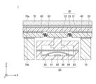
- FIG. 1 is a cross-sectional view (part 1) illustrating a switch device according to a first embodiment
- FIG. 3 is a plan view illustrating the frame of the switch device according to the first embodiment
- FIG. FIG. 2 is a cross-sectional view (part 2) illustrating the switch device according to the first embodiment
- It is a figure which shows the conditions and result of an Example and a comparative example.
- FIG. 1 is a cross-sectional view (part 1) illustrating the switch device according to the first embodiment.
- the switch device 1 includes a support portion 10, a bonding layer 20, a frame 30, a bonding layer 40, a resin layer 50, a bonding layer 60, a glass layer 70, and a switch portion 80.
- the supporting portion 10 , the frame 30 , the bonding layer 40 , the resin layer 50 , and the bonding layer 60 are not essential components of the switch device 1 .
- One surface 70 a of the glass layer 70 is the outermost surface of the switch device 1 .
- Other members such as the support portion 10 and other layers are arranged on the other surface 70b side (rear surface side) of the glass layer 70 .
- the switch device 1 is mounted on, for example, a wiring board.
- the support portion 10 is arranged on the other surface 70b side (rear surface side) of the glass layer 70 and supports the glass layer 70 and the like.
- the support portion 10 can be arranged outside the switch portion 80 in a frame shape so as to surround the switch portion 80 .
- a plurality of support portions 10 may be arranged at arbitrary positions outside the switch portion 80 at intervals.
- the support portion 10 is made of resin, metal, or the like, for example.
- the parts constituting the switch section 80 may be used as the support section.
- the switch portion 80 itself may be used as the support portion. That is, the support portion may be a part of the switch portion 80 or may be the entirety of the switch portion 80 . In these cases, the supporting portion 10 shown in FIG. 1 may not be arranged. Alternatively, part or all of the switch section 80 may be used as a support section, and the support section 10 shown in FIG. 1 may be arranged separately from this.
- any pressure-sensitive adhesive or adhesive can be used for the bonding layers 20, 40, and 60.
- FIG. the pressure-sensitive adhesive refers to a layer that has adhesiveness at room temperature and adheres to an adherend with light pressure. Therefore, even when the adherend adhered to the adhesive is peeled off, the adhesive retains practical adhesive strength.
- an adhesive refers to a layer that can bind substances by being interposed between them. Therefore, when the adherend adhered to the adhesive is peeled off, the adhesive does not have practical adhesive strength.
- adhesives examples include adhesives that use polymers such as acrylic polymers, silicone polymers, polyesters, polyurethanes, polyamides, polyethers, fluorine-based polymers, and rubber-based polymers as base polymers.
- adhesives examples include polyester-based adhesives, polyurethane-based adhesives, polyvinyl alcohol-based adhesives, and epoxy-based adhesives.
- the adhesive When the adhesive is a thermosetting adhesive, it can exert peel resistance by being cured (hardened) by heating.
- the adhesive is a photocurable adhesive such as an ultraviolet curable adhesive, peeling resistance can be exhibited by curing the adhesive by irradiating it with light such as ultraviolet rays.
- the adhesive when the adhesive is a moisture-curable adhesive, it can be cured by reacting with moisture in the air, etc., so that it can be cured even if left unattended to exhibit peeling resistance.
- an adhesive or an adhesive as the bonding layer 20, an adhesive as the bonding layer 40, and an adhesive as the bonding layer 60.
- the thickness of the bonding layer 20 is preferably within 5 ⁇ m to 2 mm.
- the thickness of the bonding layer 40 is preferably 5 ⁇ m or more and 200 ⁇ m or less, more preferably 20 ⁇ m or more and 150 ⁇ m or less, and even more preferably 20 ⁇ m or more and 100 ⁇ m or less, in terms of the manufacturing method of the adhesive layer.
- the thickness of the bonding layer 60 is preferably 0.5 ⁇ m or more and 25 ⁇ m or less, more preferably 0.5 ⁇ m or more and 5 ⁇ m or less, and even more preferably 0.5 ⁇ m or more and 3 ⁇ m or less.
- FIG. 2 is a plan view illustrating the frame.
- the frame 30 has a fixed portion 31 and a movable portion 32 supported by an elastic support portion 33 with respect to the fixed portion 31 .
- the fixed part 31 has an opening, and the movable part 32 is arranged in the opening.
- the fixed portion 31 and the movable portion 32 are movably supported by a plurality of elastic support portions 33 . Only the fixed portion 31 is joined to the support portion 10 , and the movable portion 32 and the elastic support portion 33 are not joined to the support portion 10 .
- a circular opening is formed substantially in the center of the rectangular fixed part 31, and the circular movable part 32 is arranged in the opening.
- the diameter of the movable portion 32 can be, for example, about 10 mm to 30 mm.
- the three elastic support portions 33 are arranged at positions dividing the movable portion 32 in the circumferential direction into approximately three equal parts.
- the shapes of the fixed portion 31 and the movable portion 32, the number of elastic support portions 33, and the connecting positions thereof are not limited to the example shown in FIG.
- the elastic support portion 33 is, for example, a spring.
- the spring may be a leaf spring or a coil spring.
- the elastic support portion 33 may be a member other than the spring, such as rubber.
- the frame 30 can be integrally formed of resin, metal, or the like, for example.
- materials such as ABS-based resin, vinyl chloride-based resin, polypropylene-based resin, polycarbonate-based resin, and polystyrene-based resin can be used.
- materials such as aluminum and SUS can be used.
- the thickness of the frame 30 can be, for example, 0.5 mm or more and 5 mm or less.
- the resin layer 50 can be interposed between the glass layer 70 and the switch section 80 .
- the resin layer 50 is bonded onto the fixed portion 31 of the frame 30 via the bonding layer 40 .
- the resin layer 50 has flexibility.
- the thickness of the resin layer 50 is preferably 50 ⁇ m or more and 150 ⁇ m from the viewpoint of flexibility.
- materials for the resin layer 50 include polyester-based resins such as polyethylene terephthalate-based resins and polyethylene naphthalate-based resins, cycloolefin-based resins such as norbornene-based resins, polyether sulfone-based resins, polycarbonate-based resins, and acrylic-based resins.
- polyolefin-based resins polyimide-based resins, polyamide-based resins, polyimide-amide-based resins, polyarylate-based resins, polysulfone-based resins, polyetherimide-based resins, urethane-based resins, and the like.
- the resin layer 50 when the resin layer 50 is laminated under the glass layer 70, the resin layer 50 suppresses excessive deformation of the glass layer 70 and has the effect of suppressing cracking of the glass layer 70. , the durability when the glass layer 70 is repeatedly elastically deformed can be improved. By changing the thickness of the resin layer 50, the amount of deformation of the glass layer 70 can be controlled.
- a plurality of resin layers may be laminated below the glass layer 70 via a bonding layer.
- Such a laminated structure can further suppress cracking of the glass layer 70 and further improve durability when the glass layer 70 is repeatedly elastically deformed.
- the glass layer 70 is laminated on the resin layer 50 via the bonding layer 60 .
- the glass layer 70 is made of tempered glass.
- the tempered glass may be either chemically tempered glass or thermally tempered glass, but chemically tempered glass having a compressive stress layer is easier to manufacture than thermally tempered glass.
- the glass layer 70 preferably has a compressive stress of 600 MPa or more.
- chemical strengthening is to replace ions near the surface of the glass plate with ions having a large ionic radius. Ion exchange forms a compressive stress layer on the surface of the glass sheet, resulting in chemically strengthened glass.
- the glass composition in the compressive stress layer is different from the glass composition in the interior of the glass.
- soda lime glass for example, soda lime glass, aluminosilicate glass, borosilicate glass, aluminoborosilicate glass, etc.
- soda lime glass for example, soda lime glass, aluminosilicate glass, borosilicate glass, aluminoborosilicate glass, etc.
- soda lime glass or soda silicate glass is preferable, and soda lime glass is more preferable, in that the depth of the compressive stress layer does not become excessively large.
- Ion exchange can be performed, for example, by replacing Li ions on the surface of the glass plate with Na ions and/or K ions. Alternatively, Na ions on the surface of the glass plate may be replaced with K ions. These ion exchanges form a compressive stress layer on the surface of the glass sheet.
- a glass plate containing sodium When replacing Na ions with K ions, for example, a glass plate containing sodium may be brought into contact with an inorganic molten salt containing potassium nitrate.
- the inorganic molten salt containing potassium nitrate preferably contains at least one salt selected from the group consisting of K2CO3 , Na2CO3 , KHCO3 , NaHCO3 , KOH and NaOH.
- the thickness of the glass layer 70 is preferably 100 ⁇ m or more.
- the glass layer used in the switch device must be elastically deformable, and considering that it can be sufficiently elastically deformed, the thickness of the glass layer 70 is preferably 200 ⁇ m or less.
- a functional layer such as an antifouling layer, an antireflection layer, a conductive layer, a reflective layer, and a decorative layer may be provided on the surface and/or the back surface of the glass layer 70 .
- the glass layer 70 is positioned on the outermost surface.
- the glass layer 70 is positioned on the outermost surface means that the glass layer 70 is substantially positioned on the outermost surface. , in the present embodiment, it is expressed that the glass layer 70 is located on the outermost surface.
- the switch section 80 is arranged on the back side of the glass layer 70 .
- the switch section 80 is arranged inside the support section 10 and on the opposite side of the frame 30 to the glass layer 70 and the like.
- the switch section 80 has a plurality of contacts including contacts that move up and down.
- the switch section 80 is a tact switch and has a housing 81, a film 82, a frame 83, a stem 84, a first contact 85 and a second contact 86.
- the second contact 86 is a contact that can move up and down.
- the housing 81 and the frame 83 each have a square shape and are arranged facing each other with an adhesive film 82 interposed therebetween.
- the film 82 is arranged, for example, to close the opening of the housing 81 .
- the stem 84 is held by the frame 83 so as to be vertically slidable.
- a first contact 85 and a second contact 86 are arranged on the bottom surface of the housing 81 .
- the second contact 86 is spaced apart from the first contact 85 and arranged above the first contact 85 .
- the film 82 and the second contact 86 are configured to be elastically deformable.
- the housing 81, film 82, frame 83, and stem 84 are made of resin, for example.
- the illustration of external connection terminals electrically connected to the first contact 85 and the second contact 86 is omitted.
- the switch unit 80 is not limited to a tact switch, and may be a membrane switch or the like.
- FIG. 3 is a cross-sectional view (part 2) illustrating the switch device according to the first embodiment, showing a state in which one surface 70a of the glass layer 70 is pushed in the direction of the arrow.
- the thickness of the glass layer 70 is preferably 100 ⁇ m or more and 200 ⁇ m or less.
- the glass layer 70 can be elastically deformed and locally recessed.
- the glass layer 70 is elastically deformed together with the resin layer 50 and the bonding layer 60 to move the movable portion 32 of the frame 30, thereby moving the first contact 85 and the second contact 85 of the switch portion 80.
- Contact (conduction) and non-contact (non-conduction) of the contact 86 are switched.
- the glass layer 70 can be elastically deformed, for example, so as to sink vertically by about 0.5 mm to 2 mm.
- the first contact 85 and the second contact 86 of the switch section 80 are out of contact (non-conducting state) when the glass layer 70 is not pressed. Therefore, as shown in FIG. 3, when the glass layer 70 is pressed and deformed, the stem 84 of the switch portion 80 is pressed accordingly, the film 82 and the second contact 86 are elastically deformed, and the second contact 86 is deformed. When the first contact 85 is approached, the first contact 85 and the second contact 86 come into contact with each other and become conductive. When the force pushing on the glass layer 70 is removed, the glass layer 70 returns to the state of FIG. 1 and the first contact 85 and the second contact 86 are again out of contact.
- the glass layer 70 can be elastically deformed.
- the contacts of the switch section 80 are slid up and down along with the local deformation of the glass layer 70, and the plurality of contacts of the switch section 80 are switched between conduction and non-conduction. be able to.
- the switch device 1 Since the outermost surface of the switch device 1 is the glass layer 70, it is possible to improve scratch resistance, solvent cleanability, and texture compared to the case where the outermost surface is made of resin. Further, since the glass layer 70 is made of tempered glass, the switch device 1 can have sufficient strength and durability as compared with the case where the glass layer 70 is made of untempered glass. In addition, since the switch device 1 is a sliding type switch, it is possible to obtain a tactile sensation and reduce the risk of malfunction.
- Example 1 a switch device having the structure shown in FIG. 1 was manufactured.
- the glass layer 70 chemically strengthened glass having a compressive stress of 600 MPa was used, and the thickness was set to 200 ⁇ m.
- PET was used as the material of the resin layer 50, and the thickness was set to 100 ⁇ m.
- the bonding layer 60 is made of an adhesive, made of epoxy resin, and has a thickness of 1 ⁇ m.
- Example 2 In Example 2, as the glass layer 70, chemically strengthened glass having a compressive stress of 600 MPa was used, and the thickness was set to 150 ⁇ m. A switch device was fabricated in the same manner as in Example 1 except for the above.
- Example 3 In Example 2, as the glass layer 70, chemically strengthened glass having a compressive stress of 600 MPa was used, and the thickness was set to 100 ⁇ m. A switch device was fabricated in the same manner as in Example 1 except for the above.
- Comparative Example 1 In Comparative Example 1, as the glass layer 70, chemically strengthened glass having a compressive stress of 600 MPa was used, and the thickness was set to 300 ⁇ m. A switch device was fabricated in the same manner as in Example 1 except for the above.
- Comparative Example 2 In Comparative Example 2, as the glass layer 70, chemically strengthened glass having a compressive stress of 600 MPa was used, and the thickness was set to 50 ⁇ m. A switch device was fabricated in the same manner as in Example 1 except for the above.
- Comparative Example 3 In Comparative Example 3, untempered glass was used as the glass layer 70, and the thickness was set to 200 ⁇ m. A switch device was fabricated in the same manner as in Example 1 except for the above.
- Comparative Example 4 In Comparative Example 4, untempered glass was used as the glass layer 70, and the thickness was set to 100 ⁇ m. A switch device was fabricated in the same manner as in Example 1 except for the above.
- Comparative Example 1 even if a chemically strengthened glass having a compressive stress of 600 MPa is used as the glass layer 70, if the thickness is 300 ⁇ m, the strength is too high to be elastically deformed. It was confirmed that it was not possible to switch between conduction and non-conduction of the part. Further, from Comparative Example 2, it was confirmed that even if chemically strengthened glass having a compressive stress of 600 MPa was used as the glass layer 70, sufficient strength could not be obtained if the thickness was 50 ⁇ m. Moreover, from Comparative Examples 3 and 4, it was confirmed that when untempered glass was used as the glass layer 70, sufficient strength was not obtained even when the thickness was 100 ⁇ m and 200 ⁇ m.
- Reference Signs List 1 switch device 10 support portion 20, 40, 60 joining layer 30 frame 31 fixed portion 32 movable portion 33 elastic support portion 50 resin layer 70 glass layer 70a one surface 70b other surface 80 switch portion 81 housing 82 film 83 frame 84 stem 85 first contact 86 second contact
Landscapes
- Chemical & Material Sciences (AREA)
- Life Sciences & Earth Sciences (AREA)
- Engineering & Computer Science (AREA)
- Chemical Kinetics & Catalysis (AREA)
- General Chemical & Material Sciences (AREA)
- Geochemistry & Mineralogy (AREA)
- Materials Engineering (AREA)
- Organic Chemistry (AREA)
- Push-Button Switches (AREA)
- Contacts (AREA)
Abstract
Description
支持部10は、ガラス層70の他方の面70b側(裏面側)に配置され、ガラス層70等を支持する。支持部10は、例えば、スイッチ部80の外側に、スイッチ部80を囲むように枠状に配置することができる。或いは、複数の支持部10をスイッチ部80の外側の任意の位置に間隔を置いて配置してもよい。支持部10は、例えば、樹脂や金属等から形成される。
接合層20、40、及び60としては、任意の粘着剤又は接着剤を使用できる。本明細書において、粘着剤とは、常温で接着性を有し、軽い圧力で被着体に接着する層をいう。従って、粘着剤に貼着した被着体を剥離した場合にも、粘着剤は実用的な粘着力を保持する。一方、接着剤とは、物質の間に介在することによって物質を結合できる層をいう。従って、接着剤に貼着した被着体を剥離した場合には、接着剤は実用的な接着力を有さない。
フレーム30は、ガラス層70とスイッチ部80との間に介在することができる。図1の例では、フレーム30は、接合層20を介して、支持部10上に接合されている。図2は、フレームを例示する平面図である。図2に示すように、フレーム30は、固定部31と、固定部31に対して弾性支持部33で支持された可動部32とを有している。固定部31は開口部を有し、開口部内に可動部32が配置されている。固定部31と可動部32は、複数の弾性支持部33により可動自在に支持されている。なお、支持部10と接合されるのは固定部31のみであり、可動部32及び弾性支持部33は支持部10には接合されない。
樹脂層50は、ガラス層70とスイッチ部80との間に介在することができる。図1の例では、樹脂層50は、接合層40を介して、フレーム30の固定部31上に接合されている。樹脂層50は、可撓性を有する。樹脂層50の厚さは、可撓性の観点から50μm以上150μmであることが好ましい。樹脂層50の材料としては、例えば、ポリエチレンテレフタレート系樹脂やポリエチレンナフタレート系樹脂等のポリエステル系樹脂、ノルボルネン系樹脂等のシクロオレフィン系樹脂、ポリエーテルサルホン系樹脂、ポリカーボネート系樹脂、アクリル系樹脂、ポリオレフィン系樹脂、ポリイミド系樹脂、ポリアミド系樹脂、ポリイミドアミド系樹脂、ポリアリレート系樹脂、ポリサルホン系樹脂、ポリエーテルイミド系樹脂、ウレタン系樹脂等が挙げられる。
ガラス層70は、接合層60を介して樹脂層50上に積層されている。ガラス層70は、強化ガラスからなる。強化ガラスは、化学強化ガラスでも熱強化ガラスでもよいが、圧縮応力層を有する化学強化ガラスの方が熱強化ガラスよりも製造が容易である。ガラス層70は、圧縮応力が600MPa以上であることが好ましい。
スイッチ部80は、ガラス層70の裏面側に配置される。図1の例では、スイッチ部80は、支持部10の内側であり、かつ、フレーム30のガラス層70等とは反対側に配置されている。
実施例1では、図1に示す構造のスイッチ装置を作製した。ガラス層70として、圧縮応力が600MPaの化学強化ガラスを用い、厚さは200μmとした。また、樹脂層50の材料にはPETを用い、厚さは100μmとした。また、接合層60は接着剤とし、材料にはエポキシ樹脂を用い、厚さは1μmとした。
実施例2では、ガラス層70として、圧縮応力が600MPaの化学強化ガラスを用い、厚さは150μmとした。それ以外は実施例1と同様にしてスイッチ装置を作製した。
実施例2では、ガラス層70として、圧縮応力が600MPaの化学強化ガラスを用い、厚さは100μmとした。それ以外は実施例1と同様にしてスイッチ装置を作製した。
比較例1では、ガラス層70として、圧縮応力が600MPaの化学強化ガラスを用い、厚さは300μmとした。それ以外は実施例1と同様にしてスイッチ装置を作製した。
比較例2では、ガラス層70として、圧縮応力が600MPaの化学強化ガラスを用い、厚さは50μmとした。それ以外は実施例1と同様にしてスイッチ装置を作製した。
比較例3では、ガラス層70として、未強化ガラスを用い、厚さは200μmとした。それ以外は実施例1と同様にしてスイッチ装置を作製した。
比較例4では、ガラス層70として、未強化ガラスを用い、厚さは100μmとした。それ以外は実施例1と同様にしてスイッチ装置を作製した。
実施例1~3及び比較例1~4で作製したスイッチ装置について、ガラス層70を押したときにガラス層70が弾性変形してスイッチ部80を押せるか否かを確認した。具体的には、ガラス層70側から図3の矢印方向に荷重5Nの力で押したときにスイッチ部80が非導通から導通に切り替わるか否かを確認し、切り替わった場合を〇、切り替わらなかった場合を×とした。
実施例1~3及び比較例1~4で作製したスイッチ装置について、強度試験を行い、ガラス層70にクラックが入るか否かを目視で確認し、クラックが確認できなかった場合を〇、クラックが確認できた場合を×とした。強度試験は、JIS C4526-1:2021に規定されているスプリングハンマー試験に準拠して行った。なお、スプリングハンマー試験によりスイッチ装置に加えた力は、0.5Jである。
評価結果を図4に示す。図4の実施例1~3より、ガラス層70として圧縮応力が600MPaの化学強化ガラスを用い、かつ厚さを100μm~200μmとすることで、スイッチ部の導通と非導通を切り替えることができ、かつ十分な強度が得られることが確認できた。
10 支持部
20,40,60 接合層
30 フレーム
31 固定部
32 可動部
33 弾性支持部
50 樹脂層
70 ガラス層
70a 一方の面
70b 他方の面
80 スイッチ部
81 ハウジング
82 フィルム
83 フレーム
84 ステム
85 第1接点
86 第2接点
Claims (9)
- 強化ガラスからなるガラス層と、
前記ガラス層の裏面側に配置されたスイッチ部と、を有し、
前記ガラス層の厚さは、100μm以上200μm以下であり、
前記スイッチ部は、上下に可動する接点を含む複数の接点を備え、
前記ガラス層が押されると、前記ガラス層が弾性変形して複数の前記接点の導通と非導通とが切り替わる、スイッチ装置。 - 前記ガラス層は、圧縮応力層を有する化学強化ガラスである、請求項1に記載のスイッチ装置。
- 前記ガラス層は、圧縮応力が600MPa以上である、請求項2に記載のスイッチ装置。
- 前記ガラス層と前記スイッチ部との間にフレームが介在し、
前記フレームは、固定部と、固定部に対して弾性支持部で支持された可動部と、を有し、
前記ガラス層が押されると、前記ガラス層が弾性変形して前記可動部を可動させ、複数の前記接点の導通と非導通とが切り替わる、請求項1乃至3のいずれか一項に記載のスイッチ装置。 - 前記ガラス層の裏面側に、前記ガラス層を支持する支持部を有する、請求項1乃至4のいずれか一項に記載のスイッチ装置。
- 前記支持部は、前記スイッチ部の一部又は全部である、請求項5に記載のスイッチ装置。
- 前記支持部は、前記スイッチ部の外側に配置される、請求項5又は6に記載のスイッチ装置。
- 前記ガラス層と前記スイッチ部との間に接合層が介在する、請求項1乃至7のいずれか一項に記載のスイッチ装置。
- 前記ガラス層と前記スイッチ部との間に樹脂層が介在する、請求項1乃至8のいずれか一項に記載のスイッチ装置。
Priority Applications (5)
| Application Number | Priority Date | Filing Date | Title |
|---|---|---|---|
| EP23760126.5A EP4489046A4 (en) | 2022-02-28 | 2023-02-24 | SWITCHING DEVICE |
| JP2024503272A JP7651061B2 (ja) | 2022-02-28 | 2023-02-24 | スイッチ装置 |
| KR1020247026453A KR20240157018A (ko) | 2022-02-28 | 2023-02-24 | 스위치 장치 |
| US18/835,862 US20250149272A1 (en) | 2022-02-28 | 2023-02-24 | Switch device |
| CN202380020856.2A CN118661237A (zh) | 2022-02-28 | 2023-02-24 | 开关装置 |
Applications Claiming Priority (2)
| Application Number | Priority Date | Filing Date | Title |
|---|---|---|---|
| JP2022-029745 | 2022-02-28 | ||
| JP2022029745 | 2022-02-28 |
Publications (1)
| Publication Number | Publication Date |
|---|---|
| WO2023163128A1 true WO2023163128A1 (ja) | 2023-08-31 |
Family
ID=87766158
Family Applications (1)
| Application Number | Title | Priority Date | Filing Date |
|---|---|---|---|
| PCT/JP2023/006840 Ceased WO2023163128A1 (ja) | 2022-02-28 | 2023-02-24 | スイッチ装置 |
Country Status (7)
| Country | Link |
|---|---|
| US (1) | US20250149272A1 (ja) |
| EP (1) | EP4489046A4 (ja) |
| JP (1) | JP7651061B2 (ja) |
| KR (1) | KR20240157018A (ja) |
| CN (1) | CN118661237A (ja) |
| TW (1) | TW202401467A (ja) |
| WO (1) | WO2023163128A1 (ja) |
Families Citing this family (1)
| Publication number | Priority date | Publication date | Assignee | Title |
|---|---|---|---|---|
| JP7640081B2 (ja) * | 2021-04-21 | 2025-03-05 | 日東電工株式会社 | スイッチ装置 |
Citations (7)
| Publication number | Priority date | Publication date | Assignee | Title |
|---|---|---|---|---|
| JPH06203679A (ja) | 1993-01-08 | 1994-07-22 | Yazaki Corp | グロメット |
| US5747757A (en) * | 1996-09-10 | 1998-05-05 | Monopanel Technologies, Inc. | Tamper resistant membrane switch |
| JP2012059685A (ja) * | 2010-09-03 | 2012-03-22 | Samsung Electro-Mechanics Co Ltd | 抵抗膜方式のタッチパネル |
| US20140218640A1 (en) * | 2013-02-05 | 2014-08-07 | Corning Incorporated | Glass keyboard |
| US20190033923A1 (en) * | 2017-07-26 | 2019-01-31 | Apple Inc. | Computer with keyboard |
| JP2020129299A (ja) * | 2019-02-08 | 2020-08-27 | ホーチキ株式会社 | 発信機及び消火栓装置 |
| JP2022029745A (ja) | 2020-08-05 | 2022-02-18 | 株式会社タチバナ | 建築限界確認治具 |
Family Cites Families (2)
| Publication number | Priority date | Publication date | Assignee | Title |
|---|---|---|---|---|
| JPS58151620A (ja) * | 1982-03-03 | 1983-09-08 | Casio Comput Co Ltd | シ−ト状小型電子機器 |
| EP1282144B1 (de) * | 2001-08-02 | 2006-10-18 | Richard Wöhr GmbH | Eingabe- und/oder Anzeigevorrichtung |
-
2023
- 2023-02-24 US US18/835,862 patent/US20250149272A1/en active Pending
- 2023-02-24 EP EP23760126.5A patent/EP4489046A4/en active Pending
- 2023-02-24 WO PCT/JP2023/006840 patent/WO2023163128A1/ja not_active Ceased
- 2023-02-24 CN CN202380020856.2A patent/CN118661237A/zh active Pending
- 2023-02-24 TW TW112106902A patent/TW202401467A/zh unknown
- 2023-02-24 JP JP2024503272A patent/JP7651061B2/ja active Active
- 2023-02-24 KR KR1020247026453A patent/KR20240157018A/ko active Pending
Patent Citations (7)
| Publication number | Priority date | Publication date | Assignee | Title |
|---|---|---|---|---|
| JPH06203679A (ja) | 1993-01-08 | 1994-07-22 | Yazaki Corp | グロメット |
| US5747757A (en) * | 1996-09-10 | 1998-05-05 | Monopanel Technologies, Inc. | Tamper resistant membrane switch |
| JP2012059685A (ja) * | 2010-09-03 | 2012-03-22 | Samsung Electro-Mechanics Co Ltd | 抵抗膜方式のタッチパネル |
| US20140218640A1 (en) * | 2013-02-05 | 2014-08-07 | Corning Incorporated | Glass keyboard |
| US20190033923A1 (en) * | 2017-07-26 | 2019-01-31 | Apple Inc. | Computer with keyboard |
| JP2020129299A (ja) * | 2019-02-08 | 2020-08-27 | ホーチキ株式会社 | 発信機及び消火栓装置 |
| JP2022029745A (ja) | 2020-08-05 | 2022-02-18 | 株式会社タチバナ | 建築限界確認治具 |
Non-Patent Citations (1)
| Title |
|---|
| See also references of EP4489046A4 |
Also Published As
| Publication number | Publication date |
|---|---|
| JPWO2023163128A1 (ja) | 2023-08-31 |
| KR20240157018A (ko) | 2024-10-31 |
| EP4489046A1 (en) | 2025-01-08 |
| US20250149272A1 (en) | 2025-05-08 |
| JP7651061B2 (ja) | 2025-03-25 |
| TW202401467A (zh) | 2024-01-01 |
| CN118661237A (zh) | 2024-09-17 |
| EP4489046A4 (en) | 2025-06-25 |
Similar Documents
| Publication | Publication Date | Title |
|---|---|---|
| JP7640081B2 (ja) | スイッチ装置 | |
| JP5999340B2 (ja) | タッチパネル用ガラスフィルム積層体、及びタッチパネル、並びにタッチパネル用ガラスフィルム積層体の製造方法 | |
| KR102131962B1 (ko) | 커버 윈도우의 제조장치 및 커버 윈도우의 제조방법 | |
| WO2023163128A1 (ja) | スイッチ装置 | |
| KR100937124B1 (ko) | 푸시 버튼 스위치 및 이 푸시 버튼 스위치의 제작에 사용되는 접점 스프링 부착 시트 | |
| CN109790059B (zh) | 玻璃树脂层叠体的制造方法及玻璃树脂层叠体 | |
| EP2151841A1 (en) | Key sheet | |
| GB2412244A (en) | Switches | |
| CN112739516A (zh) | 柔性模具的制造方法、柔性模具用的基材、以及光学部件的制造方法 | |
| JP2006344511A (ja) | クリックばね付きシート及びその製造方法及びこれを用いたスイッチ | |
| WO2025069528A1 (ja) | スイッチ装置 | |
| JP2008177155A (ja) | 操作スイッチ構造 | |
| WO2024158021A1 (ja) | スイッチ装置、電子装置 | |
| JP2025153470A (ja) | スイッチ装置 | |
| JP7731024B1 (ja) | 積層体及びスイッチ装置 | |
| JPWO2023163128A5 (ja) | ||
| JPH10125172A (ja) | 押釦スイッチ部材 | |
| WO2025205161A1 (ja) | スイッチ装置 | |
| WO2025069521A1 (ja) | スイッチ装置 | |
| WO2025204780A1 (ja) | 電子装置 | |
| WO2025197756A1 (ja) | スイッチ装置 | |
| JP2006127800A (ja) | 板ばね付きシート及びこれを用いたスイッチ装置 | |
| CN101419872A (zh) | 带突起的可动接点体的制造方法 |
Legal Events
| Date | Code | Title | Description |
|---|---|---|---|
| 121 | Ep: the epo has been informed by wipo that ep was designated in this application |
Ref document number: 23760126 Country of ref document: EP Kind code of ref document: A1 |
|
| ENP | Entry into the national phase |
Ref document number: 2024503272 Country of ref document: JP Kind code of ref document: A |
|
| WWE | Wipo information: entry into national phase |
Ref document number: 18835862 Country of ref document: US |
|
| WWE | Wipo information: entry into national phase |
Ref document number: 202380020856.2 Country of ref document: CN |
|
| WWE | Wipo information: entry into national phase |
Ref document number: 2023760126 Country of ref document: EP |
|
| NENP | Non-entry into the national phase |
Ref country code: DE |
|
| ENP | Entry into the national phase |
Ref document number: 2023760126 Country of ref document: EP Effective date: 20240930 |
|
| WWP | Wipo information: published in national office |
Ref document number: 18835862 Country of ref document: US |
|
| WWW | Wipo information: withdrawn in national office |
Ref document number: 2023760126 Country of ref document: EP |